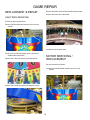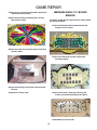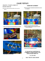
1
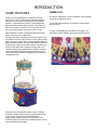
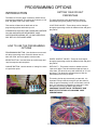
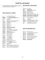
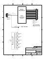
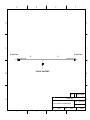
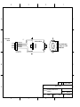
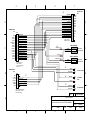
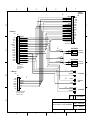
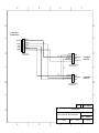
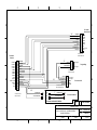
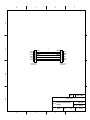
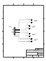
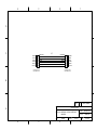
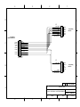
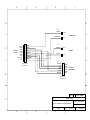
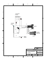
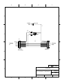
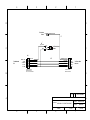
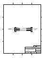
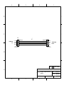
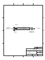
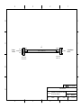
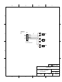
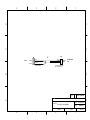
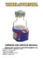
OWNERS AND SERVICE MANUAL
INNOVATIVE CONCEPTS IN ENTERTAINMENT INC.
10123 MAIN STREET, CLARENCE, NY 14031
SERVICE: 1–716–759–0360
FAX: 1–716–759–0884
E–MAIL: [email protected]
WEBSITE: icegame.com
1
TABLE OF CONTENTS
INTRODUCTION
GAME FEATURES
GAME PLAY
INSTALLATION
BEFORE YOU BEGIN
INSTALLATION
PROGRAMMING OPTIONS
INTRODUCTION
HOW TO ADJUST OPTIONS
USING THE PROGRAMMING OPTIONS
MAINTENANCE
QUICK TROUBLESHOOTING
GAME REPAIR
OPERATIONAL BACKGROUND
TROUBLESHOOTING PHILOSOPHY
MECHANICAL REPAIR
PARTS LISTINGS
SCHEMATICS
WARRANTY INFORMATION
2
INTRODUCTION
GAME FEATURES
GAME PLAY
Thank you for purchasing the new Wheel of Fortune"
game from I.C.E. By combining the great play appeal of
Cyclone", the great name recognition of the immensely
popular TV show Wheel of Fortune", and by adding the
spinning wheel and great game sounds, we’ve taken the
“Quick coin” game to a new level. You’ll find this game to
be a huge money earner now and for years to come.
The object of the game is to spin the wheel in the hope that
it stops at the big bonus values.
To spin the wheel the player must stop the rotating light in
the “Spin Zone”.
This will automatically spin the wheel for the player. The
wheel spin is totally random. As is where the wheel stops.
Game cabinetry is stylish, yet bright and attractive using
“glitter” decals to give it a glitzy look.
The game has been designed as a centerpiece game that
will enhance the look of any location. Thick 16 gauge metal
panels and marine grade water resistant plywood make the
game extremely durable. The top of the cabinet is made of
a special high impact styrene that is easy to maintain, and
a thick acrylic dome that is extremely strong, and more
scratch resistant than polycarbonate. Up higher, the glitter
covered marquee flashes the wheel of fortune letters to
attract game players. Brilliant backlighting of the playfield
completes the look.
Electronics and sounds are the state of the art in digital
technology. Robust design ensures a long trouble free life
for your game. The game is very flexible with its
programming options to allow it to be tailored to most
locations easily. (For special non–standard options, call our
service department for details).
3
BEFORE YOU BEGIN
TOOLS YOU WILL NEED
The game normally comes fully assembled and ready for
use.
WARNING: WHEN INSTALLING THIS GAME, A
GROUNDED A.C. RECEPTACLE MUST BE USED.
FAILURE TO DO SO COULD RESULT IN INJURY TO
YOURSELF OR OTHERS. FAILURE TO USE A
GROUNDED RECEPTACLE COULD ALSO CAUSE
IMPROPER GAME OPERATION, OR DAMAGE TO THE
ELECTRONICS
If however, you need to disassemble or reassemble the
marquee to the game for any reason, all that is needed is a
Phillips screwdriver, 7/64” Allen wrench and a 7/16” socket
and ratchet.
DO NOT DEFEAT OR REMOVE THE GROUNDING
PRONG ON THE POWER CORD FOR THE SAME
REASON AS GIVEN ABOVE. USING AN IMPROPERLY
GROUNDED GAME COULD VOID YOUR WARRANTY.
Place the game into its final location and use the adjusting
feet to level the game. This is important to do, to assure
proper operation of the game.
HAVE A QUALIFIED ELECTRICIAN CHECK YOUR A.C.
RECEPTACLE TO BE SURE THE GROUND IS
FUNCTIONING PROPERLY.
CAUTION: CHECK THAT THE A.C. VOLTAGE RATING
ON THE BACK OF THE GAME MATCHES THE A.C.
VOLTAGE OF YOUR LOCATION.
THE POWER SUPPLY IS NOT VOLTAGE ADJUSTABLE.
TO OPERATE THE GAME AT VOLTAGES OTHER THAN
THOSE IT WAS DESIGNED FOR, PLEASE CONTACT
OUR SERVICE DEPARTMENT FOR VOLTAGE
CONVERSION INFORMATION.
INSTALLATION
The game comes ready to play with just a few simple
things to keep in mind.
Plug the game into the A.C. outlet and turn power to the
game on. The switch for the game is located on a power
module inside the game.
1. When installing the game, be sure you use a
grounded A.C. outlet. If necessary, have it checked
to be sure the ground is good.
It is now time to program your game&&..
THIS GAME IS DESIGNED TO DISSIPATE STATIC
ELECTRICITY THROUGH THE GROUNDING PLANE OF
THE GAME. IF THE A.C. GROUND DOES NOT WORK,
THE GAME COULD DISCHARGE STATIC ELECTRICITY
THROUGH THE GAME CIRCUITRY, WHICH COULD
CAUSE DAMAGE.
Make sure the game is level after installation. It is
necessary to make sure the game is level so the game will
work properly.
4
PROGRAMMING OPTIONS
INTRODUCTION
SETTING YOUR PAYOUT
PERCENTAGE
The Wheel of Fortune" game is extremely flexible from a
programming standpoint. This allows the customer to “fine
tune” the game to his or her exact needs.
The game has three basic adjustments to allow for
percentaging the game properly. They are as follows:
This section will describe in detail each of the
programming options and how they work.
LIGHT RING VALUES - These values can be changed
through programming to allow for different ticket and game
play values.
PLEASE READ THIS SECTION THOROUGHLY BEFORE
CALLING OUR SERVICE DEPARTMENT. MOST
QUESTIONS REGARDING SET–UP AND OPERATION
WILL BE FULLY EXPLAINED HERE.
HOW TO USE THE PROGRAMMING
OPTIONS
PROGRAMMING BUTTON - Use this button to enter and
exit the programming mode. Press this button once to
enter the mode, and once again to exit the mode.
WHEEL JACKPOT VALUES - These can be changed
through programming to allow for different ticket and game
play values.
SELECT BUTTON - Use this button to scroll through and
“step” through the various options.
CHANGE BUTTON - Use this button to “change” the value
of a particular option.
DIFFICULTY - This makes it easier or harder to hit the
“spin zone” target. This will make the wheel spin less or
more often. The wheel is set up with a difficulty of “6” from
the factory. This allows the average player to spin the
wheel about once every 20 times.
This setting is what we recommend you start with. It is
important to keep it difficult enough to spin the wheel to
keep the game interesting, but not so hard that it can’t be
done. It is important for bystanders to see that it is easy
enough to do, so they will want to play as well.
CHANGING THIS SETTING IS THE EASIEST AND
MOST EFFECTIVE WAY OF CHANGING YOUR
PERCENTAGING.
5
PROGRAMMING OPTIONS
FORMULATING YOUR PERCENTAGES
ATTRACT TIME
(OPTION #5)
The game comes from the factory based on a average 25
cent play, and a 1 cent retail ticket value, with a payback of
40%.
This option determines the duration of time between attract
modes in minutes. The range for this option is 1–30. The
default value for this option is “2”.
AT THE END OF THIS SECTION ARE SOME BASIC
EXAMPLES OF PAYOUT COMBINATIONS AND THE
FORMULA FOR TRYING YOUR OWN COMBINATIONS.
IF YOU ARE UNABLE TO MAKE ANY OF THESE
COMBINATIONS WORK FOR YOU, PLEASE CONTACT
OUR SERVICE DEPARTMENT.
ATTRACT MODE TYPE
(OPTION #6)
This option determines what type of attract mode (if any) is
used. Setting a “0” turns the attract mode off. Setting a “1”
makes sound only. Setting a “2” spins the wheel only.
Setting a “3” gives both sound and the wheel spin. The
default value for this option is “3”
COINS PER CREDIT
(OPTION #1)
This option determines how many coins are needed to
obtain 1 “credit”. Setting a “0” puts the game into free
play mode. The range for this option is 0-10. The
default value for this option is “1”.
JUST FOR SPINNING TICKETS
(OPTION #7)
Enabling this option will give the player a predetermined
amount of extra or “bonus” tickets before the wheel is
spun. The tickets will begin to pay out as the wheel begins
to spin. The range for this option is 0–50. Setting a “0”
turns this option OFF. The default value of this option is “0”.
GAMES PER CREDIT
(OPTION #2)
This option determines how many games or turns the
player gets per credit. This option is useful if you have a
minimum coin value that is so high you need to give the
customer multiple games to get good value. The range for
this option is 1–10. The default value for this option is “1”.
CREDIT DISCOUNTING
(OPTION #3)
This determines the number of consecutive credits
(without playing a game) given before dispensing a free
game.
For example, if this option was set to “2”, each time 2 coins
IN A ROW were put in, a free game would be given.
The range for this option is 0–10. The default value for this
option is “0”.
VOLUME
(OPTION #4)
This option determines the sound volume of the game.
Setting a “0” turns the sound to minimum. Setting a “10”
6
PROGRAMMING OPTIONS
ZONE VALUES
(OPTIONS #8–27)
WHEEL JACKPOT VALUES
The jackpot values can be adjusted through programming
and by changing the decals themselves. This helps to
adjust for differing game play and ticket values
The ring light values can be adjusted through programming
and by changing the decals on the playfield itself.
This determines the ring light values for zones
1–20. Each zone can be set to pay out 0–20 tickets. The
chart below will give you the default values for each zone,
as well as translate the option number to the zone. Please
see the chart above to realize the proper relationship
between zone, option number, and position on the
playfield. Example, Zone 10 is to the immediate right of the
“spin zone” and is option #16.
OPTION#
8
9
10
11
12
13
14
15
16
17
18
19
20
21
22
23
24
25
26
27
ZONE#
1
2
3
4
5
6
7
8
9
10
11
12
13
14
15
16
17
18
19
20
NON–HOME JACKPOT VALUE, ZONE
10
(OPTION #28)
DEFAULT
3
3
4
4
5
5
6
7
8
10
10
8
7
6
5
5
4
4
3
3
This is the white jackpot wedge BELOW the words Wheel
of Fortune on the center hub of the wheel. The numbers
are removable and can be replaced with the other values
supplied with the game.
The range for this option is 0–1000. The default value for
this option is “300”
HOME JACKPOT VALUE
ZONE 0
(OPTION #29)
This is the white jackpot wedge ABOVE the words Wheel
of Fortune on the center hub of the wheel. The numbers
are removable and can be replaced with the other values
supplied with the game.
The range for this option is 0–1000. The default value for
this option is “500”
7
PROGRAMMING OPTIONS
BIG JACKPOT LOCKUP
(OPTION #30)
WINABILITY
(OPTION #32)
This option will allow the game to “Lock up” when either
of the jackpot wedges are hit. This allows the location to
save on tickets if the jackpot wedges are set to pay out a
high amount. To clear the lock up, open the coin door
and hit the “Ticket Reset” button on the cash box
enclosure. The range for this option is 0–1. Setting a “1”
turns this feature ON. The default value for this option is
“0” (off).
If you wish to keep your percentages more accurate, or have
some especially talented players that always win easily, you
may want to use this option.
WHEEL DIFFICULTY
(OPTION #31)
this option determines how hard it is to stop the light in
the “Spin Zone”. This adjusts the size of the “time
window” to make it easier or harder. The numbers
available represent MILLISECONDS (1/1000th of a
second).
What win ability does is this. You set the “wheel difficulty”
option to a number that is harder to win such as “3” ( a one
in 60 hit average). You then set this option to “20”. This
means that after 20 games are played, the difficulty window
will open to full open making it much easier to win. This way
you’ll get a winner about every 20 games or so, but the more
talented player would have to be much better to win. Since
this still works based solely on skill, it remains fair and
winnable for the advanced player, but will get easier to allow
less skillful people to win as well.
The range for this option is 0–100. Setting a “0” turns this
option OFF. The default value for this option is “0”.
The range for this option is 1–20. The default value for
this option is “6”.
When the game is set to “6”, average players will
hit the spin zone approximately once every 20 times.
This is where we feel the game works best, balancing
difficulty with the excitement of being able to hit the
target on a consistent basis.
CHANGE THIS SETTING TO RASIE OR LOWER THE
PAYBACK PERCENTAGE.
In the event that the wheel difficulty needs to be
changed, please use the chart below to give you a rough
idea of how your changes will affect game play. These
numbers will vary according to the age group and skill of
your customers.
MILLISECONDS
1
2
3
4
5
6
7
8
1 IN XXXXXX HITS
COUNTER TYPE
(OPTION #33)
This option determines how the money counters work in the
game. Setting a “0” has the counters work so that each time
a COIN is inserted the counter will increment 1. Setting a “1”
has the counter work that each time a CREDIT (one OR
MORE coins) is inserted and earned, the counter will
increment by 1. The default setting for this option is “0”
(Advances once for each coin inserted).
SOUND LOOP
(OPTION #34)
This option will loop a money payout sound and lock up the
game until all tickets have been dispensed IN THE EVENT
OF A JACKPOT. This can add extra excitement to the game.
The range for this option is 0–1. Setting a “1” turns this
option on. The default value for this option is “0”, OFF.
1 IN 300
1 IN 120
1 IN 60
1 IN 45
1 IN 30
1 IN 20 (DEF)
1 IN 10
1 IN 5
8
PROGRAMMING OPTIONS
FACTORY RESET
(OPTION #35)
This option is used to GLOBALLY RE–SET all of the
software settings to the FACTORY DEFAULT. Setting a “1”
will re–set all of the settings to their factory default as when
you first received the game. The default value for this
option is “0” (NO RE–SET).
IF YOU HAVE ANY QUESTIONS OR
COMMENTS, PLEASE CONTACT OUR
SERVICE DEPARTMENT AT:
716–759–0360
MON. THRU FRI. 8AM–6PM EST
GAME SETTING EXAMPLES
The examples shown below are intended to act as a guide
when setting up your game. Please be advised these are
generalities and your game in all likelihood will need to be
adjusted for your particular clientele.
25–cent play - 1–cent ticket
(spin zone) 7–6–6–5–5–4–4–3–3–2
Jackpot 500 - 300
6 MS Difficulty setting (average 1 in 20 spins)
80–cent play - 5–cent ticket
(spin zone) 5–4–3–2–2–2–2–2–1–1
Jackpot 500 - 300
6 MS Difficulty setting (average 1 in 20 spins)
50–cent play - 1–cent ticket
(spin zone) 10–10–9–9–8–8–7–7–7–7
Jackpot 900 - 900
7 MS Difficulty setting (average 1 in 15 spins)
5–cent play - 1–cent ticket
(spin zone) 2–1–0–0–0–0–0–0–0–0
Jackpot Bankrupt - Bankrupt
5 MS Difficulty setting (average 1 in 30 spins)
PAYOUT CALCULATION FORMULA
If you would like to try to figure out your own payout
calculations, please use the formula on the next page.
9
Total Wheel Value
= 905 + J1 + J2
1. Assign Ticket Values to A–J, y (normally 19), and Jackpot 1 (J1; normally 300) and Jackpot 2
(J2; normally 500)
2. Add up values of A–D
3. Add up values of E–J and Divide by 6
4. Add the number you get in Step 2 to the number you get in Step 3
5. Take the number you get in Step 4 and divide it by 5
6. Take the number you get in Step 5 and multiply it by (y)
7. Add 905, J1 and J2 and divide that number by 20
Add the number you get form Step 6 and Step 7 together and divide that number by 20
*** This calculation assumes that the values on both sides of the spin zone are set the same.
If you set the 2 sides different, run this calculation for both sides and average.
10
MAINTENANCE
GENERAL MAINTENANCE
TICKET DISPENSERS
This game has been designed to be as trouble and
maintenance free as possible.
The biggest problem ticket dispensers have is ticket dust
blocking the optical detectors. It is a good idea to
occasionally use compressed air to remove the dust from
the dispensers.
With this in mind the only basics are to keep the game
clean. Below are the main areas to take care of with
specific directions.
DOME
The dome should be cleaned with a soapy water solution if
covered with water based dirt such as food products. After
cleaning with soapy water, polish with a commercial plastic
polish or a spray furniture polish. These have lubricating
oils that condition the plastic and keep it shiny and clear
looking. Never use regular glass cleaners as the ammonia
in them actually damages the plastic and dulls it.
Any deep scratches can be reduced or eliminated with a
scratch removing polish and buffing wheel.
CABINET
The cabinet plastic and decals can be cleaned with soapy
water or spray furniture polish. DO NOT use any alcohol or
petroleum based cleaners as they could damage the
plastic or printed parts.
COIN MECHANISMS
The coin mechanisms should be cleaned periodically, as
they will accumulate dirt which will cause the coins to stick.
Remove the coin mech and clean them in a dish detergent
solution and a stiff brush. Dry thoroughly and re–install.
11
QUICK TROUBLESHOOTING
GAME WILL NOT TAKE OR ADD MONEY CORRECTLY
·
Micro switch not working or returning properly. Check and repair or replace as necessary.
·
Bad Harnessing or connector. Check w/ohm meter and repair as necessary.
·
Game programming set incorrectly. Check programming option and re–program if necessary.
·
Bad Main P.C. Board. Check and repair or replace as necessary.
STOP BUTTON WILL NOT FLASH WHEN GAME HAS CREDITS, OR WORK WHEN PUSHED
·
Micro switch not working properly. Test and replace as necessary.
·
Micro switch popped out of housing. Snap back into housing.
·
Burned out light bulb. Replace light bulb.
·
Bad harnessing or connector. Check w/ohm meter and repair as necessary.
·
Bad Main P.C. Board. Check and repair or replace as necessary.
GAME HAS NO SOUND
·
Bad speaker. Check w/ohm meter for 4 or 8–ohm load. If not within this range, replace.
·
Volume level set incorrectly. Check volume level in programming, and adjust if necessary.
·
Bad Harnessing or connector. Check w/ohm meter and repair as necessary.
·
Bad Main P.C. Board. Check and repair or replace as necessary
TICKET DISPENSER DOES NOT WORK OR WORKS IMPROPERLY
·
Bad ticket dispenser. Repair or replace as necessary.
·
Bad harnessing or connector. Check w/ohm meter and repair as necessary.
·
Bad Main P.C. Board. Check and repair or replace as necessary.
·
Game out of tickets. Add tickets
·
Optical sensor on ticket dispenser dirty. Remove paper fuzz and debris with a soft brush.
NO FLORESCENT LIGHTING
·
Bulb burned out. Replace bulb.
·
Electronic ballast bad. Replace ballast.
·
Harness bad or harness unplugged. Check w/ohm meter and plug in, repair or replace as necessary.
·
No A.C. power to the game or Main fuse bad. Check fuse and A.C. power.
ALARM SOUND DOES NOT WORK OR FALSE TRIGGERS (OPTIONAL)
·
Bad Main P.C. Board. Check and repair or replace as necessary
·
Bad Harnessing. Check w/ohm meter and repair or replace as necessary.
·
Alarm Plum bob set up improperly. Check for proper plum bob clearance and adjust as necessary.
·
Game not level. Level game to be sure plum bob is operating correctly.
·
Game unplugged. Plug game back in and test for proper operation.
WHEEL WILL NOT SPIN OR SPINS SLOWLY
·
Bad Motor. Check or replace as necessary
·
Bad harnessing. Check and repair as necessary
·
Bad motor cooling fan causing overheating of motor. Replace fan.
·
Clicker solenoid not disengaging properly. Check and replace solenoid if necessary.
·
Clicker return spring. Check and replace spring if necessary.
12
QUICK TROUBLESHOOTING
LIGHT RING DOES NOT LIGHT
·
Bad Main P.C. Board. Fix or replace main board.
·
Bad light ring board. Find problem board and replace or repair as necessary.
·
Bad light ring board harnessing. Repair as necessary.
·
Blown fuse on Main P.C. Board. Replace fuse. Check for problems.
MARQUEE DOES NOT LIGHT
·
Fuse blown on main P.C. Board. Replace fuse.
·
Harnessing between marquee and main board bad. Check and repair as necessary.
·
Bad Marquee P.C. Board. Repair or replace as necessary.
CREDITS OR TICKETS OWED DISPLAYS DON’T WORK PROPERLY
·
Bad Display P.C. Board. Repair or replace Display board
·
Bad Main P.C. Board. Repair or replace Main board.
·
Bad display harnessing. Repair as necessary.
CAN’T ENTER OR EXIT PROGRAMMING OR OTHER ADJUSTMENT MODES
·
Bad programming or adjustment buttons. Replace buttons. Check harnessing.
·
Harnessing fell off back of button. Re–attach harnessing.
·
Bad Main P.C. Board. Repair or replace Main board.
13
GAME REPAIR
TROUBLESHOOTING PHILOSOPHY
WARNING: ALWAYS REMOVE POWER TO
THE GAME BEFORE ATTEMPTING ANY
SERVICE, UNLESS NEEDED FOR SPECIFIC
TESTING.
FAILURE TO OBSERVE THIS PRECAUTION
COULD RESULT IN SERIOUS INJURY TO
YOURSELF OR OTHERS.
To find problems with the game, always first check what
should be obvious. See that the game is plugged in, and
that all of the fuses on the game are good. This includes
the fuse that is located INSIDE the power module.
Next, check to see that all of the connectors are firmly
seated and that none of the wires have been pulled out of
them.
OPERATIONAL
BACKGROUND
When trying to find out if specific components are bad or
not, try swapping them with components from another
player station to see if the problem moves with the
component, or stays where it was. This will help you to
know if you have a problem with a specific component, or
maybe a problem with either the wiring or the Main P.C.
Board.
The Wheel of Fortune" game has been manufactured with
modular design in mind. Almost everything in the game can
be EASILY removed for servicing. This makes it much
easier for the repairman as he /she can work in a quieter
less distracting environment away from the Game Room
floor. The game relies on 1 brushed DC for the mechanical
spinning of the wheel. This motor can be accessed easily
for service.
Use extreme caution when using probes or voltmeters if
the game is powered up. If doing continuity checks, it is
important to disconnect the harnessing at both ends, as
attached they may yield erroneous results.
Coin and low ticket sensing are done with conventional
micro switches. In all areas of critical importance, optical
sensors were developed specifically, and optimized for
their particular application.
If a P.C. Board is suspected as the cause of a problem,
check to see that all of the components on the board are
firmly attached. Pay special attention to any socketed
devices.
All P.C. Boards are made of premium quality board
material and use time proven components to assure you of
the most reliable designs possible.
If light bulbs are suspected, swap them with one that is
known to work to narrow the problem down to either a bulb
or P.C. Board.
We have put forth our best efforts and tested this game
extensively to assure the best possible performance under
the widest variety of operating conditions. We are ALWAYS
however interested in our customers input for product
improvement. If you have any questions or comments
please feel free to contact our service department.
I.C.E. SERVICE DEPARTMENT
716–759–0360
NORMAL BUSINESS HOURS ARE:
MONDAY - FRIDAY, 8:00 AM TO 5:00 PM
14
GAME REPAIR
REPLACEMENT & REPAIR
Remove the plastic spacers that hold the board in place.
Remove the connector to the board.
LIGHT RING SERVICING
Service the light ring as follows:
Remove the Allen bolts that hold the cover on to the
cabinet.
Assemble in the reverse order.
Lift the cover up and remove the dome. (See dome
replacement instructions)
MOTOR SERVICING /
REPLACEMENT
Remove the 2 wheel clickers by unscrewing them.
Service the motor as follows:
Remove the Allen bolts that hold the cover on to the
cabinet.
Remove the Light Ring graphics by lifting the ring up.
15
GAME REPAIR
MARQUEE BULB / P.C. BOARD
SERVICE
Lift the cover up and remove the dome. (See dome
replacement instructions)
Remove the wheel by unscrewing the 3 screws
that hold it in place.
To replace a light bulb or remove the P.C. Board follow
the directions below.
Remove the Phillips head screws that hold the
marquee cover in place.
Remove the motor by unscrewing the screws that
hold it in place.
Remove the bolts that hold the inside wood
housing together.
Disconnect the plug on the motor from the motor
harness.
Remove the main p.c. board by removing the
screws and connector that hold it in place.
Assemble in reverse order.
Reassemble in reverse order.
16
GAME REPAIR
CREDITS / TICKETS OWED P.C.
BOARD SERVICE
DOME REPLACEMENT
Remove the Allen head bolts that hold the cover to
the cabinet.
Remove the Allen bolts that hold the cover on to the
cabinet.
Lift up the cover and remove the Dome.
Set the new dome onto the playfield centered
evenly in the game.
Lift the cover up to access the Display P.C. Boards.
Unscrew and remove the boards for service.
Lower the cover and bolt into place.
IF YOU HAVE ANY QUESTIONS OR
COMMENTS, PLEASE CONTACT OUR
SERVICE DEPARTMENT AT:
Reassemble in reverse order.
716–759–0360
17
MON. THRU FRI. 8AM–6PM EST
PARTS LISTINGS
ELECTRONIC / ELECTRICAL
Parts denoted with * indicate available as part of
a specially discounted spares kit.
WF2002X
2005*
2008*
PP2011X*
WF2034X
WF2037X*
WF2038X*
WF2039X*
WF2040X*
WF2041X*
2110
2117
2305
CC2032X*
CC2035X*
2295
2315
MECHANICAL PARTS
211
BW250X
FP1004
HR1019
1024
1026
WF1050
CP1051
WF1051
WF1052
WF1053
WF1054
WF1055
WF1056
WF1060*
CG1068
HR2005
AR2007
BW2017
BW2018
2027
CC2027
HH2050
2364G
WF3001
WF3004*
WF3005
WF3024X
HH5005
5101X
WF6001X*
6321
BW8284X
8312*
WF9010
Low Ticket Micro Switch
PLL Bulb Socket Assembly
Leg Leveler Mounting Bracket
Leveler Foot
Ticket Bin
Bracket, Low Ticket Switch Mounting
Clicker Pole, Teflon coated
Tilt Sensor
Wheel Hub
Wheel Pin, 1”
Wheel Pin, 1.5”
Wheel Pin, 2”
Wheel Pin, non extension
Flag, Opto beam breaker
Clicker Spring
Bushing, bronze oil impregnated
Large round white push button
Speaker, 6” x 9”
PLL Bulb Retaining Clip
PLL Bulb Support
Fan, DC 12 Volt
Power Cord, 20ft.
Power Module
Fan Guard
Cabinet Cover
Clicker (pointer)
Marquee Housing
Dome Assembly, with tape
Ticket Dispenser
Mech Holder Assembly
Parts Package
3/8” E–Clip
Workhorse 6 Ballast, ( WH6–120–L)
Bulb, PL–L 40W/41/RS/IS Florescent
Cover, clicker sensor (black card)
Transformer
906 Light Bulb
Solenoid, Spring Tensioner
Wheel Motor, D.C.
Main P.C. Board
Marquee P.C. Board
Clicker Position P.C. Board., Large
Clicker Position P.C. Board, Small
Wheel Position P.C. Board, Outer
Wheel Position P.C. Board, Inner
TIP 122 Transistor
IC, 74hc14
IC, 74hc273
Tickets Owed Display P.C. Board
Light ring board (banana board)
Fuse, MDQ6 (6 amp slo blo)
Fuse, MDQ3 (3 amp slo blo)
DECALS AND GRAPHICS
WF7001
WF7002
WF7004
WF7005
WF7006
WF7013
WF7014
WF7015
WF7027
WF9001
18
Side Panel Decal
Center Wheel (sold w / WF7013)
Podium Side Decal
Instruction Plate Decal
Ticket Arrow Decal
Outer Ring ( sold w / WF7002)
Clicker overlay glitter decal
Monaco Logo Decal
Marquee Panel
Service Manual
4
3
2
1
#WF2002XTRANSFORMER ASY
D
1
2
3
ORANGE
YELLOW
BLUE
BLUE
13"
BLACK
GREEN/YELLOW
BLACK
YELLOW
ORANGE
#WF2002
TRANSFORMER
(2-51-0118)
3 PIN PLUG #2206
SOLID PIN #2100S
PINS 1 & 3: 20-14 AWG
MALE PIN # 8260
BROWN
RED
RED
BROWN
1
2
3
4
5
6
7
8
9
10
11
12
11.3 VAC
8 VAC
16.8 VAC
16.8 VAC
8 VAC
11.3 VAC
14 VAC
16 VAC
16 VAC
14 VAC
12 PIN PLUG #2106
PINS 2-6,9,12 : 20-14 AWG
MALE PIN # 8260
PINS 1,7,10-11: 14-18 AWG
MALE PIN # 2422
C
* Add 6" of Large Spiral Wrap
Starting 4" from the 12-Pin Plug
15"
GREEN/YELLOW
#PC20217
D
C
TO BASE OF TRANSFORMER
RD
RD
16 VAC @ 10.45A
14 AWG
OR
B
BK
OR
BU
115 VAC 60~
18 AWG
BU
BN
BK
BN
B
11.3 VAC @ 9.0A
14 AWG
16.8 VAC @ 3.75A
18 AWG
14 VAC @ 2.75A
18 AWG
YL
YL
A
QTY 1
8 VAC @ 0.5A
18 AWG
Wheel Of Fortune
TITLE
DESCRIPTION
3
2
A
FILENAME
WFREV2.VSD
DRAWN BY
MMARTIN
#WF2002X - TRANSFORMER ASY.
2/29/00
DATE
4
PER GAME
REVISED
6/13/01
PAGE
1
1 OF 25
4
3
2
1
D
D
C
C
To Cabinet Frame
#652
25"
To Cabinet Frame
43 "
GREEN/YELLOW
GREEN/YELLOW
#652
#8068
TO BASE OF TRANSFORMER
B
B
QTY 1
Wheel Of Fortune
TITLE
A
DESCRIPTION
3
2
A
FILENAME
WFREV2.VSD
DRAWN BY
MMARTIN
#WF2004X - GROUNDING STRAP
2/29/00
DATE
4
PER GAME
REVISED
6/26/01
PAGE
1
2 OF 25
4
3
2
1
D
C
D
To Wheel Motor
Harness
8"
+ 13VDC
+ 13VDC
WHEEL
WHEEL
1
2
3
4
# PP2011- MOTOR
C
LIGHT BLUE
LIGHT BLUE
BLACK/BLUE
BLACK/BLUE
# 2163 - DIODE 1N4004
2 " # 8380 - 1/8 " CLEAR
SHRINK TUBE
4 PIN PLUG #2099
SOLID PIN #2100S
B
B
QTY 1
Wheel Of Fortune
TITLE
A
DESCRIPTION
3
# WF2008X - WHEEL MOTOR
ASSEMBLY
2/29/00
DATE
4
PER GAME
2
REVISED
5/3/01
A
FILENAME
WFREV2.VSD
DRAWN BY
MMARTIN
PAGE
1
3 OF 25
4
3
2
1
To Clicker/
Control Panel
Ext.
74"
ORANGE
ORANGE
ORANGE
RED
BLACK
BLACK/WHITE
BLACK/WHITE
yellow
yellow/green
yellow/white
VIOLET/BLACK
violet/gray
RED/BLACK
YELLOW/BLACK
D
To Mainboard
P4
C
P4
1
2
3
4
5
6
7
8
9
10
11
12
13
14
15
5SV
CCNT1
SOL1
TCNT1
LOCKOUT1
PUSH1
COIN1
CLICK1
LPUSH1
+ 12VDC
+ 12VDC
+ 12VDC
D GND
D GND
D GND
RED/BLACK
violet/blue
YELLOW/BLACK
violet/yellow
tan/black
violet/gray
violet/green
yellow/white
VIOLET/BLACK
orange * 2
ORANGE
ORANGE+orange
BLACK/WHITE
black/white
BLACK/WHITE+black/white
15 PIN CAP #2367
FEMALE PIN #2102
48"
B
P13
1
2
3
4
5
6
7
KEY
+ 5VDC
CLK2
DDATA
+ 12VDC
P GND
KEY
KEY
RED
yellow/green
yellow
ORANGE
BLACK
KEY
+ 12VDC
+ 12VDC
+ 12VDC
+ 5VDC
P GND
D GND
D GND
DDATA
CLK
CLICK
LPUSH
PUSH
5SV
SOL
black
red
#PC20224
12v COUNTER
0000000000
C
orange #2558
TICKET COUNTER
violet/yellow #2558
black
red
76"
75 "
80"
72"
# 2293 7-PIN AMP HOUSING
AMP CONTACT PIN #2201
# 2239 KEY PLUG.156
orange
#650
.110
black/white
#650
.110
tan/black
#651
.187
orange
#651
.187
DESCRIPTION
B
To Lockout
Coils
violet/green
#653T
.250
black/white
#653T
.250
To Coin Switch
PER GAME
2
A
FILENAME
WFREV2.VSD
DRAWN BY
MMARTIN
#WF2011AX - P2 STATION HARNESS
2/29/00
DATE
3
To Coin Lamps
Wheel Of Fortune
TITLE
A
#PC20224
12v COUNTER
0000000000
QTY 1
4
D
COIN COUNTER
violet/blue #2558
15 PIN PLUG #2144
SPLIT PIN #2100
20-14 AWG PIN #8260
PINS 12 + 15
To Mainboard
P13
1
2
3
4
5
6
7
8
9
10
11
12
13
14
15
REVISED
6/13/01
PAGE
1
4 OF 25
4
3
2
1
To Clicker/
Control Panel
Ext.
65"
ORANGE
ORANGE
ORANGE
RED
BLACK
BLACK/WHITE
BLACK/WHITE
white/yellow
white/green
white
VIOLET/BLACK
gray
RED/BLACK
YELLOW/BLACK
D
To Mainboard
P2
C
P2
1
2
3
4
5
6
7
8
9
10
11
12
13
14
15
5SV
CCNT1
SOL1
TCNT1
LOCKOUT1
PUSH1
COIN1
CLICK1
LPUSH1
+ 12VDC
+ 12VDC
+ 12VDC
D GND
D GND
D GND
RED/BLACK
white/blue
YELLOW/BLACK
gray/yellow
tan/black
gray
gray/green
white
VIOLET/BLACK
orange * 2
ORANGE
ORANGE+orange
BLACK/WHITE
black/white
BLACK/WHITE+black/white
15 PIN CAP #2367
FEMALE PIN #2102
25"
1
2
3
4
5
6
7
KEY
+ 5 VDC
CLK2
DDATA
+ 12VDC
P GND
KEY
KEY
RED
white/green
white/yellow
ORANGE
BLACK
KEY
black
red
#PC20224
12v COUNTER
0000000000
C
TICKET COUNTER
gray/yellow #2558
black
red
71"
67"
68"
62"
# 2293 7-PIN AMP HOUSING
AMP CONTACT PIN #2201
# 2239 KEY PLUG.156
orange
#650
.110
black/white
#650
.110
tan/black
#651
.187
orange
#651
.187
gray/green
#653T
.250
black/white
#653T
.250
DESCRIPTION
B
To Lockout
Coils
To Coin Switch
PER GAME
2
A
FILENAME
WFREV2.VSD
DRAWN BY
MMARTIN
#WF2011X - P1 STATION HARNESS
2/29/00
DATE
3
To Coin Lamps
Wheel Of Fortune
TITLE
A
#PC20224
12v COUNTER
0000000000
QTY 1
4
D
orange #2558
To Mainboard
P12
P12
+ 12VDC
+ 12VDC
+ 12VDC
+ 5VDC
P GND
D GND
D GND
DDATA
CLK
CLICK
LPUSH
PUSH
5SV
SOL
COIN COUNTER
white/blue #2558
15 PIN PLUG #2144
SPLIT PIN #2100
20-14 AWG PIN #8260
PINS 12 + 15
B
1
2
3
4
5
6
7
8
9
10
11
12
13
14
15
REVISED
6/13/01
PAGE
1
5 OF 25
4
3
2
1
D
D
To Wheel Sensor
Extention Harness
WSHORT
WLONG
D GND
+ 12VDC
WHOME
C
1
2
3
4
5
6
white/red
white/brown
black/white
orange
white/orange
6 PIN PLUG #2173
SOLID PIN #2100S
orange
white/red
black/white
white/orange
33"
27"
30"
C
+12VDC
InnerWheelShort
P GND
InnerWheelHome
To Inner Wheel
Sensor PCB
4 PIN AMP HOUSING #2429
AMP CONTACTS #2201
*2 orange
white/brown
*2 black/white
B
1
2
3
4
1
2
3
+12VDC
OuterWheelLong
P GND
To Outer Wheel
Sensor PCB
B
3 PIN AMP HOUSING #2945
AMP CONTACT #2201
QTY 1
Wheel Of Fortune
TITLE
A
DESCRIPTION
3
2
A
FILENAME
WFREV2.VSD
DRAWN BY
MMARTIN
#WF2013AX - Wheel Sensor Harness
2/29/00
DATE
4
PER GAME
REVISED
6/13/01
PAGE
1
6 OF 25
4
3
2
1
D
D
36"
To Control
Panel Harness
ORANGE
ORANGE
RED
BLACK
BLACK/WHITE
yellow
yellow/green
VIOLET/BLACK
violet/gray
C
+12VDC
+12VDC
+5VDC
P GND
D GND
D Data
Clock
Button Light
Button
C
9 PIN CAP #2551
FEMALE PIN #2102
To Station
Harness
B
1
2
3
4
5
6
7
8
9
+ 12VDC
+ 12VDC
+ 12VDC
+ 5VDC
P GND
D GND
D GND
D Data
Clock
Clicker
Button Light
Button
5SV
SOL
1
2
3
4
5
6
7
8
9
10
11
12
13
14
15
10"
ORANGE
ORANGE
ORANGE
RED
BLACK
BLACK/WHITE
BLACK/WHITE
yellow
yellow/green
yellow/white
VIOLET/BLACK
violet/gray
RED/BLACK
YELLOW/BLACK
1
2
GRAY/BLACK
3
VIOLET
GRAY/BLACK
BLACK/WHITE
yellow/white
ORANGE
33"
5 PIN AMP HOUSING #2419
AMP CONTACTS #2201
RED/BLACK
#651
.187
#2909
.187
M
YELLOW/BLACK
#651
.187
#2909
.187
M
7"
RED/BLACK
#651
.187
YELLOW/BLACK
#651
.187
1
2
3
4
5
To Light Ring
Bonus Light-
Bonus Light +
Bonus Light D GND
Clicker
+12VDC
DESCRIPTION
#WF2013X - CLICKER/CONTROL
PANEL EXTENTION
2/29/00
DATE
3
QTY 2
PER GAME
Wheel Of Fortune
TITLE
A
B
To Clicker PCB
To Clicker Solenoid
#WF2013BX- SOLENIOD EXTENTION
4
Bonus Light+
3 PIN PLUG #2206
SOLID PIN #2100S
29"
15 PIN PLUG #2144
SPLIT PIN #2100
VIOLET
2
REVISED
6/13/01
A
FILENAME
WFREV2.VSD
DRAWN BY
MMARTIN
PAGE
1
7 OF 25
4
3
2
1
D
D
C
9VDC
CLOCK
D GND
DATA
LATCH
P GND
1
2
3
4
5
6
BROWN
RED
ORANGE
YELLOW
GREEN
BLUE
C
15 "
BROWN
RED
ORANGE
YELLOW
GREEN
BLUE
6 PIN PLUG #2173
SOLID PIN #2100S
1
2
3
4
5
6
9VDC
CLOCK
D GND
DATA
LATCH
P GND
6 PIN PLUG #2173
SOLID PIN #2100S
B
B
QTY 1
Wheel Of Fortune
TITLE
A
DESCRIPTION
3
#WF2014X - RING INTERCONNECT
HARNESS
2/29/00
DATE
4
PER GAME
2
REVISED
5/3/01
A
FILENAME
WFREV2.VSD
DRAWN BY
MMARTIN
PAGE
1
8 OF 25
4
3
2
1
D
D
92"
brown/gray
red/gray
.250 #653T
To Left Speaker
Of Station 2
.250 #653T
95"
C
red/gray
To Mainboard
P6
To Left Speaker
Of Station 1
P6
KEY
LSPKR +
LSPKR RSPKR +
RSPKR KEY
1
2
3
4
5
6
7
brown/gray
KEY
red/gray * 2
brown/gray * 2
red/white * 2
brown/white * 2
KEY
C
.250 #653T
.250 #653T
102 "
red/white
7 PIN AMP HOUSING #2293
CONTACT PIN #2201
PINS 1 & 7: KEY PLUG #2239
brown/white
84"
B
.250 #653T
To Right Speaker
Of Station 1
.250 #653T
red/white
brown/white
B
.250 #653T
To Right Speaker
Of Station 2
.250 #653T
QTY 1
Wheel Of Fortune
TITLE
A
DESCRIPTION
3
2
A
FILENAME
WFREV2.VSD
DRAWN BY
MMARTIN
# WF2018X - SPEAKER HARNESS
2/29/00
DATE
4
PER GAME
REVISED
7/23/01
PAGE
1
9 OF 25
4
3
2
1
D
D
C
D GND
5VDC
DATA
P GND
12VDC
CLOCK
black/white
RED
yellow
BLACK
ORANGE
yellow/green
1
2
3
4
5
6
12"
black/white
RED
yellow
BLACK
ORANGE
yellow/green
6 PIN PLUG #2173
SOLID PIN #2100S
C
1
2
3
4
5
6
D GND
5VDC
DATA
P GND
12VDC
CLOCK
6 PIN PLUG #2173
SOLID PIN #2100S
B
B
QTY 2
Wheel Of Fortune
TITLE
A
DESCRIPTION
3
#WF2022X - DISPLAY INTERFACE
HARNESS
2/29/00
DATE
4
PER GAME
2
REVISED
6/13/01
A
FILENAME
WFREV2.VSD
DRAWN BY
MMARTIN
PAGE
1
10 OF 25
4
3
2
1
D
D
32"
LIGHT BLUE
yellow/red
black
yellow/blue
yellow/violet
BLACK
6 PIN PLUG #2173
SOLID PIN #2100S
To Light Ring
Extention Harness
C
P GND
D DATA
P GND
CLK 1
BLTCH
P GND
+ 13VDC
+ 13VDC
1
2
3
4
5
6
7
8
9
1
2
3
4
5
6
+13VDC
CLOCK 1
P GND
D DATA
B LTCH
P GND
To Light Ring
Harness
BLACK
yellow/blue
black
yellow/red
yellow/violet
BLACK
C
LIGHT BLUE
LIGHT BLUE
9 PIN PLUG #2292
SPLIT PIN #2100
32"
LIGHT BLUE
B
BLACK
6 PIN PLUG #2173
SOLID PIN #2100S
1
2
3
4
5
6
+13VDC
CLOCK 1
GND
D DATA
B LTCH
GND
To Light Ring
Harness
QTY 1
DESCRIPTION
3
2
A
FILENAME
WFREV2.VSD
DRAWN BY
MMARTIN
# WF2050AX - LIGHT RING HARNESS
2/29/00
DATE
4
PER GAME
Wheel Of Fortune
TITLE
A
REVISED
5/4/01
B
PAGE
1
11 OF 25
4
3
2
1
D
D
C
To Mainboard
P8
P8
P GND
D DATA
P GND
CLK 1
BLTCH
P GND
KEY
+ 13VDC
+ 13VDC
1
2
3
4
5
6
7
8
9
70"
BLACK
yellow/blue
black
yellow/red
yellow/violet
BLACK
BLACK
yellow/blue
black
yellow/red
yellow/violet
BLACK
KEY
LIGHT BLUE
LIGHT BLUE
LIGHT BLUE
LIGHT BLUE
9 PIN PLUG #2292
SPLIT PIN #2100
PIN 7: KEY PLUG #2549
C
1
2
3
4
5
6
7
8
9
P GND
D DATA
P GND
CLK 1
BLTCH
P GND
To Light Ring
Harness
+ 13VDC
+ 13VDC
9 PIN CAP #2551
FEMALE PIN #2102
B
B
QTY 1
Wheel Of Fortune
TITLE
A
DESCRIPTION
3
# WF2050X - LIGHT RING EXTENTION
HARNESS
2/29/00
DATE
4
PER GAME
2
REVISED
6/13/01
A
FILENAME
WFREV2.VSD
DRAWN BY
MMARTIN
PAGE
1
12 OF 25
4
3
2
1
D
D
P7
C
To Mainboard
P7
P GND
P GND
+12UVDC
KEY
DDATA
+12UVDC
D GND
BLTCH
CLK5
1
2
3
4
5
6
7
8
9
92"
BLACK
BLACK
ORANGE/BLACK
brown/blue
brown/red
ORANGE/BLACK
BLACK/WHITE
brown/green
BLACK
BLACK
ORANGE/BLACK
KEY
brown/red
ORANGE/BLACK
BLACK/WHITE
brown/green
brown/blue
9 PIN PLUG #2292
SPLIT PIN #2100
PIN 4: KEY PLUG #2549
7
8
1
3
4
2
6
5
P GND
P GND
+12UVDC
CLK 5
To Marquee
DDATA
Display PCB
+12UVDC
D GND
BLTCH
8 PIN HOUSING #2405
WITH AMP CONTACT #2201
* Start Spiral Wrap (# 8069) 34" From 9-Pin Plug
Cut Spiral Wrap 26" To Cover 18" Of Harness
ORANGE/BLACK
ORANGE/BLACK
brown/blue
brown/red
brown/green
BLACK/WHITE
BLACK
BLACK
B
1
2
3
4
5
6
7
8
+ 12UVDC
+ 12UVDC
CLK 5
DDATA
BLTCH
D GND
BLACK
BLACK
QTY 1
DESCRIPTION
3
PER GAME
2
A
FILENAME
WFREV2.VSD
DRAWN BY
MMARTIN
#WF2051X - MARQUEE HARNESS
2/29/00
DATE
4
B
Wheel Of Fortune
TITLE
A
C
REVISED
6/13/01
PAGE
1
13 OF 25
4
3
2
1
D
D
P9
C
WSHORT
To Mainboard
P9
WLONG
D GND
+ 12 VDC
WHOME
1
2
3
4
5
6
77"
white/red
white/red
white/gray
white/brown
BLACK/WHITE + black/white
ORANGE
white/orange
6 PIN PLUG #2173
SOLID PIN #2100S
PIN 4: 20-14 AWG #8260
1
2
3
4
5
6
white/brown
BLACK/WHITE
ORANGE
white/orange
C
WSHORT
To Wheel
Sensor Harness
WLONG
D GND
+ 12 VDC
WHOME
6 PIN CAP #2366
FEMALE PIN #2102
17"
white/gray
#PC20217
black/white
#PC20217
B
To Tilt Sensor
B
* Add #2611 - 1/4" Shrink
tube (cut at 1 1/2") To each
Ring Terminal
QTY 1
Wheel Of Fortune
TITLE
A
DESCRIPTION
3
#WF2052X - TILT/WHEELSENSOR EXT.
HARNESS
2/29/00
DATE
4
PER GAME
2
REVISED
6/13/01
A
FILENAME
WFREV2.VSD
DRAWN BY
MMARTIN
PAGE
1
14 OF 25
4
3
2
1
D
D
24"
C
GREEN/YELLOW
#652
To Bolt on
Ticket
Dispenser
24"
To Station
Harness
T RUN
T SENSE
12 VDC
P GND
1
2
3
4
5
violet/blue
BLACK + black
violet/white
ORANGE + orange
GREEN/YELLOW
violet/white
violet/blue
ORANGE
BLACK
T Sense
P GND
To Ticket
T Run
Dispenser
+ 12VDC
orange
1
violet/red
2
21"
* Add 6" of Spiral Wrap (# 8069)
+ 12VDC
T Out
#651
.187
black
B
RED FLASHING LED #8212
WITH LED HOLDER #1017
2 PIN MOLEX HOUSING #2089
MINI KK PIN #2074
violet/red
28 "
#649
.187
To Low Ticket
Switch
B
QTY 2
DESCRIPTION
3
2
A
FILENAME
WFREV2.VSD
DRAWN BY
MMARTIN
# WF2053X - TICKET DOOR HARNESS
2/29/00
DATE
4
PER GAME
Wheel Of Fortune
TITLE
A
C
4 PIN MLX CAP #2158
FEMALE PIN #2176
PINS 2 & 4: 20-14 AWG FEMALE PIN #8177
12"
5 PIN PLUG #8129
SOLID PIN #2100S
1
2
3
4
REVISED
6/13/01
PAGE
1
15 OF 25
4
3
2
1
D
D
14"
ORANGE
.250 #653T
To Button Light
VIOLET/BLACK
C
+12VDC
+ 12VDC
+5VDC
To Clicker
P GND
Harness
D GND
D Data
Clock
Button Light
Button
1
2
3
4
5
6
7
8
9
.250 #653T
14"
ORANGE
ORANGE
RED
BLACK
black/white *2
yellow
yellow/green
VIOLET/BLACK
violet/gray
black/white
.250 #653T
C
To Button
violet/gray
.250 #653T
14"
black/white
RED
yellow
BLACK
ORANGE
yellow/green
9 PIN PLUG #2292
SPLIT PIN #2100
B
1
2
3
4
5
6
D GND
+5VDC
D Data
P GND
+12VDC
Clock
To Tickets
Owed Display
B
6 PIN PLUG #2173
SOLID PIN #2100S
QTY 2
Wheel Of Fortune
TITLE
A
DESCRIPTION
3
2
A
FILENAME
WFREV2.VSD
DRAWN BY
MMARTIN
# WF2054X - Control Panel Harness
2/29/00
DATE
4
PER GAME
REVISED
5/3/01
PAGE
1
16 OF 25
4
3
2
1
D
D
* Fuse Value: 6 Amp
# 2295 MDQ 6
#2892-POWER MODULE
CORCOM ( PELSOSSXO)
A
C
D
#651
.187
To Power Mod
Faceplate
C
B
#651
.187
10"
BROWN
GRN/YEL
BLUE
#8068
#638
.187
C
1
2
3
To Transformer
3 PIN CAP #2288
14 AWG FEMALE #2013
10"
3"
GRN/YEL
23"
GRN/YEL
B
#PC20217
BROWN
GRN/YEL
BLUE
1
2
3
To Light Ballast
Extention Harness
3 PIN CAP #2288
FEMALE #2102
To Base Of
Transformer
B
QTY 1
Wheel Of Fortune
TITLE
A
DESCRIPTION
3
# WF2055X - POWER MODULE
HARNESS
2/29/00
DATE
4
PER GAME
2
REVISED
6/13/01
A
FILENAME
WFREV2.VSD
DRAWN BY
MMARTIN
PAGE
1
17 OF 25
4
3
2
1
D
D
To Cabinet
Frame
34"
C
#652
GREEN/YELLOW
8"
voilet
#650
.110
black
#650
.110
To Ticket Reset
Button
C
P3
To Mainboard
P3
RESET BT.
T RUN
T SENSE
12 VDC
P GND
1
2
3
4
5
34"
violet
violet/white
violet/blue
ORANGE
BLACK + black
GREEN/YELLOW
violet/white
violet/blue
ORANGE
BLACK
5 PIN PLUG #8129
SOLID PIN #2100S
PIN 5: 20-14 AWG #8260
B
1
2
3
4
5
T RUN
T SENSE
12 VDC
P GND
To Ticket Door
Harness
5 PIN CAP #8130
FEMALE PIN #2102
B
QTY 1
A
DESCRIPTION
3
2
A
FILENAME
WFREV2.VSD
DRAWN BY
MMARTIN
# WF2056AX - P1 TICKET DOOR EXT.
2/29/00
DATE
4
PER GAME
Wheel Of Fortune
TITLE
REVISED
6/13/01
PAGE
1
18 OF 25
4
3
2
1
D
D
To Cabinet
Frame
#652
GREEN/YELLOW
8"
46"
C
gray/voilet
#650
.110
black
#650
.110
To Ticket Reset
Button
C
P5
To Mainboard
P5
RESET BT.
T RUN
T SENSE
12 VDC
P GND
1
2
3
4
5
48"
gray/violet
gray/white
gray/blue
ORANGE
BLACK + black
GREEN/YELLOW
gray/white
gray/blue
ORANGE
BLACK
5 PIN PLUG #8129
SOLID PIN #2100S
PIN 5: 20-14 AWG #8260
B
1
2
3
4
5
T RUN
T SENSE
12 VDC
P GND
To Ticket Door
Harness
5 PIN CAP #8130
FEMALE PIN #2102
B
QTY 1
Wheel Of Fortune
TITLE
A
DESCRIPTION
3
2
A
FILENAME
WFREV2.VSD
DRAWN BY
MMARTIN
# WF2056X - P2 TICKET DOOR EXT.
2/29/00
DATE
4
PER GAME
REVISED
6/13/01
PAGE
1
19 OF 25
4
3
2
1
D
D
C
C
To Wheel Motor
Extention Harness
+ 13VDC
+ 13VDC
WHEEL
WHEEL
1
2
3
4
LIGHT BLUE
LIGHT BLUE
BLACK/BLUE
BLACK/BLUE
27"
LIGHT BLUE
LIGHT BLUE
BLACK/BLUE
BLACK/BLUE
4 PIN PLUG #2099
SOLID PIN #2100S
1
2
3
4
+ 13VDC
+ 13VDC
WHEEL
WHEEL
To Wheel Motor
Assembly
4 PIN CAP #2101
FEMALE PIN #2102
B
B
QTY 1
Wheel Of Fortune
TITLE
A
DESCRIPTION
3
# WF2057AX - WHEEL MOTOR
HARNESS
2/29/00
DATE
4
PER GAME
2
REVISED
5/3/01
A
FILENAME
WFREV2.VSD
DRAWN BY
MMARTIN
PAGE
1
20 OF 25
4
3
2
1
D
D
C
C
P11
To Mainboard
P11
+ 13VDC
+ 13VDC
WHEEL
WHEEL
1
2
3
4
68"
LIGHT BLUE
LIGHT BLUE
BLACK/BLUE
BLACK/BLUE
LIGHT BLUE
LIGHT BLUE
BLACK/BLUE
BLACK/BLUE
4 PIN PLUG #2099
SOLID PIN #2100S
1
2
3
4
+ 13VDC
+ 13VDC
WHEEL
WHEEL
To Wheel Motor
Harness
4 PIN CAP #2101
FEMALE PIN #2102
B
B
QTY 1
Wheel Of Fortune
TITLE
A
DESCRIPTION
3
# WF2057X - WHEEL MOTOR EXT.
HARNESS
2/29/00
DATE
4
PER GAME
2
REVISED
6/13/01
A
FILENAME
WFREV2.VSD
DRAWN BY
MMARTIN
PAGE
1
21 OF 25
4
3
2
1
D
D
C
C
* Strip Back 2"
31"
To Light Ballast
Extention Harness
AC L
EARTH GND
AC N
1
2
3
BLACK
GREEN
WHITE
BLACK
GREEN
WHITE
# 8173 - 3 COND. SVT
#651
.187
#PC20217
#651
.187
To Light Ballast
* Strip Back 3" From End
Cut Black & White at 1 1/2"
3 PIN PLUG #2206
SOLID PIN #2100S
B
B
QTY 1
Wheel Of Fortune
TITLE
A
DESCRIPTION
3
# WF2058AX - LIGHT BALLAST POWER
HARNESS
2/29/00
DATE
4
PER GAME
2
REVISED
6/13/01
A
FILENAME
WFREV2.VSD
DRAWN BY
MMARTIN
PAGE
1
22 OF 25
4
3
2
1
D
D
C
C
48"
To Power
Module
AC L
EARTH GND
AC N
1
2
3
BLACK
GREEN
WHITE
BLACK
GREEN
WHITE
# 8173 - 3 COND. SVT
1
2
3
AC L
EARTH GND
AC N
To Light Ballast
Harness
3 PIN CAP #2288
FEMALE #2102
3 PIN PLUG #2206
SOLID PIN #2100S
B
B
QTY 1
Wheel Of Fortune
TITLE
A
DESCRIPTION
3
# WF2058X - LIGHT BALLAST POWER
EXTENTION HARNESS
2/29/00
DATE
4
PER GAME
2
REVISED
6/13/01
A
FILENAME
WFREV2.VSD
DRAWN BY
MMARTIN
PAGE
1
23 OF 25
4
3
2
1
D
D
To Mainboard
P10
C
P10
D GND
PRG
SEL
STEP
1
2
3
4
black/white
yellow/brown
yellow/red
yellow/orange
#650
.110
13"
#650
.110
4"
#650
.110
#650
.110
#2561 4PIN IDC
#2562 COVER STRAIN RELIEF
4"
#650
.110
#650
.110
C
PRG
SEL
STEP
B
B
QTY 1
Wheel Of Fortune
TITLE
A
DESCRIPTION
3
# WF2059AX - PROGRAMMING
BUTTONS HARNESS
2/29/00
DATE
4
PER GAME
2
REVISED
6/13/01
A
FILENAME
WFREV2.VSD
DRAWN BY
MMARTIN
PAGE
1
24 OF 25
4
3
2
1
D
D
C
C
To Fan
P GND
+ 12VDC
1
2
3
4
black
P14
28 "
orange
black
orange
4 PIN MLX CAP #2158
FEMALE PIN #2176
1
2
To Mainboard
P14
+ 12VDC
P GND
2 PIN AMP HOUSING #2240
AMP CONTACTS #2201
B
B
QTY 1
Wheel Of Fortune
TITLE
A
DESCRIPTION
3
2
A
FILENAME
WFREV2.VSD
DRAWN BY
MMARTIN
# WF2059X - FAN HARNESS
2/29/00
DATE
4
PER GAME
REVISED
6/13/01
PAGE
1
25 OF 25
Warranty
I.C.E warrants all components in the SUPER CHEXX" game to be free of defects in
materials and workmanship for a period of ninety days from the date of purchase.
This warranty does not cover items damaged due to normal wear and tear,
subjected to abuse, improperly assembled by the end user, modified, repaired, or
operated in a fashion other than that described in the service manual.
If your SUPER CHEXX" game fails to conform to the above–mentioned warranty,
I.C.E.'s sole responsibility shall be at its discretion to repair or replace any defective
component with a new or remanufactured component of equal to or greater O.E.M.
specification.
I.C.E. will assume no liability whatsoever, for costs associated with labor to replace
defective parts, or travel time associated therein.
I.C.E.'s obligation will be to ship free of charge, replacement parts by U.P.S. Ground,
U.S. mail, or other comparable shipping means. Any express mail or overnight
shipping expense is at the cost of the purchaser.
Products will be covered under warranty only when:
·
The serial number of the game with the defective parts is given.
·
The serial number of the defective part, if applicable, is given.
·
Defective parts are returned to I.C.E., shipping pre–paid, in a timely fashion, if
requested by I.C.E.
·
A copy of the sales receipt is available as proof of purchase upon request of
I.C.E.
I.C.E. distributors are independent, privately owned and operated. In their judgment,
they may sell parts or accessories other than those manufactured by I.C.E. We
cannot be responsible for the quality, suitability, or safety of any non–I.C.E. part, or
any modification, including labor, which is performed by such a distributor.