1
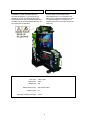
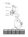
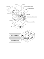
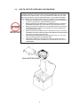
420-6831-01
REV 1
SERVICE MANUAL
DELUXE TYPE
Before using this product, read this SERVICE MANUAL carefully to understand the contents stated herein.
After reading this manual, be sure to keep it available nearby the product or somewhere convenient in
order to be able to refer to it whenever necessary.
Manufactured in the UK by
1.
CONTENTS
BEFORE USING THIS PRODUCT .......................................................................................................3
1.1. INSPECTIONS IMMEDIATELY AFTER TRANSPORTING THE PRODUCT TO THE LOCATION .4
2.
NAME OF PARTS .................................................................................................................................6
2.1. HOW TO USE THE CHIHIRO BOARD CARTON BOX.....................................................................7
2.1.1. INSTRUCTIONS .........................................................................................................................7
2.2. HOW TO USE THE CARTON BOX (GD-ROM DRIVE) ....................................................................9
3.
ASSEMBLY AND INSTALLATION ......................................................................................................10
3.1. ASSEMBLING THE BILLBOARD ....................................................................................................12
3.2. ASSEMBLING THE CABINET .........................................................................................................14
3.3. SECURING IN PLACE (ADJUSTER TUNING) ...............................................................................18
3.4. TURNING THE POWER ON ...........................................................................................................19
3.5. ASSEMBLY CHECK ........................................................................................................................20
3.5.1. MEMORY TEST........................................................................................................................20
3.5.2. C.R.T. TEST .............................................................................................................................21
3.5.3. OUTPUT TEST .........................................................................................................................22
3.5.4. GUN ADJUSTMENT.................................................................................................................22
3.6. INTERFERENCE PREVENTION WIRING ......................................................................................23
3.7. PRECAUTIONS WHEN MOVING THE MACHINE .........................................................................25
3.7.1. CAUTIONS WHEN TRANSPORTING THE MACHINE............................................................27
4.
GAME DESCRIPTION.........................................................................................................................28
4.1. GAME CONTENTS..........................................................................................................................29
4.1.1. GAME OUTLINE.......................................................................................................................29
4.1.2. GAME CONTROLS ..................................................................................................................29
4.1.3. CHARACTERS .........................................................................................................................30
4.1.4. GAME FLOW AND ON-SCREEN DISPLAY ............................................................................31
4.1.5. GAME RULES AND GAMEPLAY.............................................................................................38
4.1.6. IC CARDS [ONLY WITH THE IC CARD].................................................................................44
5.
EXPLANATION OF TEST AND DATA DISPLAY................................................................................45
5.1. SYSTEM TEST MODE ....................................................................................................................46
5.1.1. SYSTEM TEST MENU MODE .................................................................................................46
5.1.2. MEDIA BOARD TEST...............................................................................................................47
5.1.3. SYSTEM INFORMATION .........................................................................................................48
5.1.4. JVS TEST .................................................................................................................................49
5.1.5. SOUND TEST...........................................................................................................................51
5.1.6. CRT TEST ................................................................................................................................52
5.1.7. COIN ASSIGNMENTS..............................................................................................................53
5.1.8. GAME COST SETTING............................................................................................................55
5.1.9. CLOCK SETTING .....................................................................................................................56
5.1.10.
NETWORK SETTING (CORE) .............................................................................................57
5.1.11.
NETWORK SETTING MEDIA...............................................................................................58
5.2. GAME TEST MODE.........................................................................................................................59
5.2.1. INPUT TEST .............................................................................................................................60
5.2.2. OUTPUT TEST .........................................................................................................................61
5.2.3. GAME ASSIGNMENTS ............................................................................................................62
5.2.4. GUN ADJUSTMENT.................................................................................................................63
5.2.5. CARD READ/WRITE TEST ......................................................................................................65
5.2.6. CLOSE SETTING .....................................................................................................................66
5.2.7. BOOKKEEPING........................................................................................................................67
5.2.8. BACKUP DATA CLEAR............................................................................................................70
6.
CONTROL UNIT (GUN CONTROLLER) ............................................................................................71
6.1. REPLACING THE MICROSWITCH.................................................................................................72
6.2. REPLACING THE SENSOR UNIT ..................................................................................................76
6.3. REPLACING THE SOLENOID ........................................................................................................77
7.
IC CARD UNIT.....................................................................................................................................78
7.1. HOW TO CLEAN THE CARD UNIT ................................................................................................78
7.2. FIXING JAMMED CARDS ...............................................................................................................84
8.
PROJECTOR.......................................................................................................................................85
8.1. CLEANING THE SCREEN...............................................................................................................85
8.2. SETTING THE INTERFACE ............................................................................................................86
8.2.1. REMOTE CONTROL BUTTONS..............................................................................................87
8.2.2. AUTOMATIC COLOUR MATCHING ........................................................................................87
i
8.2.3. ADJUSTING THE ON-SCREEN CONTRAST..........................................................................88
8.2.4. ADJUSTING THE SCREEN BRIGHTNESS.............................................................................89
8.2.5. ADJUSTING THE ON-SCREEN DISPLAY POSITION ............................................................90
8.2.6. ADJUSTING THE SCREEN SIZE ............................................................................................91
8.2.7. CONVERGENCE ADJUSTMENT (manual colour matching) ..................................................92
8.2.8. STATIC CONVERGENCE ADJUSTMENT ..............................................................................93
8.2.9. POINT CONVERGENCE ADJUSTMENT ................................................................................94
8.2.10.
LINE CONVERGENCE ADJUSTMENT................................................................................95
9.
PERIODIC INSPECTION ....................................................................................................................96
9.1. CLEANING THE CABINET SURFACES .........................................................................................96
10.
TROUBLESHOOTING.........................................................................................................................97
10.1.
PROBLEMS NOT INVOLVING THE GAME BOARD ..................................................................97
10.1.1.
CIRCUIT PROTECTOR ........................................................................................................97
10.1.2.
REPLACING THE LED BD ...................................................................................................99
10.2.
FUSES........................................................................................................................................100
10.2.1.
REPLACING THE GUN SENSOR FUSES.........................................................................101
10.2.2.
REPLACING THE MAIN FUSE...........................................................................................102
10.3.
ERROR CODES.........................................................................................................................103
11.
DESIGN RELATED PARTS ..............................................................................................................107
12.
PARTS LIST ......................................................................................................................................108
12.1.
ASSY PTV (CTF-0500)UK .........................................................................................................108
12.2.
ASSY BILLBOARD DX (CTF-0550UK) ......................................................................................110
12.3.
ASSY FRONT PANEL(CTF-0600UK) ........................................................................................112
12.4.
ASSY PTV BASE (CTF-0650UK)...............................................................................................114
12.5.
ASSY SUB PTV BASE (CTF-0660UK) ......................................................................................116
12.6.
8.4. SPX-0530UK ASSY MASK ................................................................................................118
12.7.
ASSY CABINET DX (CTF-1000)................................................................................................119
12.8.
13.7. ASSY SUB CABI DX (CTF-1100UK) ................................................................................121
12.9.
ASSY LATCH (CTF-1170UK) ....................................................................................................125
12.10. ASSY RW UNIT (CTF-1150)......................................................................................................127
12.11. ASSY CONTROLLER HOLDER L (CTF-1300UK) ....................................................................129
12.12. ASSY CONTROLLER HOLDER R (CTF-1320UK)....................................................................131
12.13. ASSY HOLDER LIGHT (CTF-1340UK)......................................................................................133
12.14. ASSY CONTROL PANEL (CTF-2000UK)..................................................................................135
12.15. CONTROL UNIT (CTF-2100).....................................................................................................137
12.16. SENSOR UNIT (JPT-2030)........................................................................................................139
12.17. ASSY MAIN BD (CTF-4000UK) .................................................................................................141
12.18. ASSY ELEC (CTF-4100UK).......................................................................................................143
13.
WIRING DIAGRAM............................................................................................................................145
13.1.
WIRE COLOURS .......................................................................................................................145
13.2.
ELECTRICAL SCHEMATIC .......................................................................................................145
ii
1.
BEFORE USING THIS PRODUCT
To ensure the safe usage, be sure to read the following before using the product. The following instructions are
intended for the use of QUALIFIED SERVICE PERSONNEL ONLY.
If any activity is carried out on the product, this should be done only after carefully reading and sufficiently
understanding the instructions.
Only qualified service personnel should carry out maintenance on the product.
Depending on the potential risk, terms such as” WARNING!” “CAUTION” and “IMPORTANT!” are used where an
explanation is given that requires special attention. SEGA is not responsible for injury or damage caused by use in a
manner contrary to the instructions given in this document.
In order to prevent accidents warning stickers and printed instructions are applied in the places where a potentially
hazardous situation relating to the product could arise. Be sure to comply with these warnings.
Indicates that mishandling the product by disregarding this warning will cause a potentially
hazardous situation that can result in death or serious injury.
Indicates that mishandling the product by disregarding this caution will cause a potentially
hazardous situation that can result in personal injury and or material damage.
This is cautionary information that should be complied with when handling the product.
Indicates that mishandling the product by disregarding this will cause a potentially hazardous
situation that may not result in personal injury but could damage the product.
Be sure to turn off the power and disconnect from the mains supply before working on the machine.
Ensure that the correct fuses are fitted to the machine. Details of these are enclosed in the Service Manual.
Ensure that only qualified Service Engineers perform any maintenance work on the machine.
Specification changes, removal of equipment, conversion and/or additions not designated by SEGA are not permitted
and will invalidate this product’s CE conformity.
Warning labels or safety covers for personal protection etc, are component parts of the product. A potential hazard will
be created if the machine is operated while any parts have been removed. Do not operate the product if any doors, lids
or protective covers become damaged or lost. SEGA is not liable in any whatsoever for any injury and/or damage
caused by specification changes not designated by SEGA.
Before installing the product, check for the Electrical Specification Sticker, SEGA products have a sticker on which the
electrical specifications are detailed. Ensure that the product is compatible with the power supply voltage and frequency
requirements of the location in which the machine is to be installed.
Install and operate the machine only in places where appropriate lighting is available, allowing warning stickers to be
clearly read.
To ensure maximum safety for customers and operators, stickers and printed instructions describing potentially
hazardous situations are applied to potentially hazardous locations. Ensure that the product’s operating location has
sufficient lighting to allow any warnings to be read. If any sticker or printed warning is removed or defaced, do not
operate the machine until an identical item has replaced it.
Exercise great care when handling the monitor (applies only to product with monitor). Some of the monitor (TV) parts
are subject to high-tension voltage. Even after turning the power off some components are liable to high-tension
voltage. Only qualified service engineers should perform monitor repair and replacement.
In cases where commercially available monitors and printers are used, only the items relating to this product are
contained in this manual. Some commercially available equipment will have functions and reactions not referred to in
this manual. This manual should be read in conjunction with the specific manufacturer’s manual for such equipment.
Descriptions contained herein may be subject to change without prior notification.
The contents described herein are fully prepared with due care. However, should any question arise or errors be found
please contact SEGA AMUSEMENTS EUROPE LTD.
3
Descriptions contained herein may be subject to change without prior notification.
The contents described herein are fully prepared with due care. However, should any question arise or
errors be found please contact SEGA.
1.1.
INSPECTIONS IMMEDIATELY AFTER TRANSPORTING THE PRODUCT
TO THE LOCATION
• Only QUALIFIED SERVICE PERSONNEL should carry out inspection.
Normally, at the time of shipment, SEGA products are in a state to allowing usage immediately after
transporting to the location. Nevertheless, an irregular situation may arise during transportation preventing
this. Before turning on the power, check the following points to ensure that the product has been
transported safely.
• Are then any dented parts or defects (cuts, etc.) on the external surfaces of the product.?
• Are castors and leg adjusters present and undamaged?
• Do the power supply voltage and frequency requirements meet with the local supply?
• Are all wiring connectors correctly and securely connected? Unless connected in the correct direction,
connector connections cannot be made successfully. Do not insert connectors forcibly.
• Are all IC’s of each IC BD firmly inserted?
• Does the power cord have any cuts or dents?
• Do fuses meet the specified rating?
• Are such units such as monitors, control equipment, IC BD, etc. firmly secured?
• Are all earth wires connected?
• Are all accessories available?
• Can all doors and lids be opened with the accessory keys and/or tools?
4
CONCERNING THE STICKER DISPLAY
CONCERNING WARNING STICKERS
SEGA product has stickers describing the product
manufacture number (Serial Number) and
electrical specification. If you require service
assistance you will require the Serial Number.
Identical machines may have different parts fitted
internally. Only by quoting the Serial Number will
the correct parts be identified.
SEGA product has warning displays on
stickers, labels or printed instructions
adhered/attached to or incorporated in the
places where hazardous situations can arise.
The warning displays are intended for the
accident prevention of customers and service
personnel.
SPECIFICATIONS
Size (mm):
1200 x 1680
Height (mm):
2230
Weight (kg):
253
Rated Voltage (VAC):
Rated Current:
Operating Temperature Range:
220-240VAC 50Hz
3A
5-30ºC
Note: Descriptions in this manual are subject to change without prior notice.
5
2.
NAME OF PARTS
Width (mm)
PTV
PTV BASE
BILLBOARD
MAIN CABINET
When Assembled
1,140
1,200
1,170
1,140
1,200
Length (mm)
555
620
410
1,090
1,680
Height (mm)
1,670
310
385
1,010
2,230
6
Weight (kg)
100
26
18
98
253
2.1.
HOW TO USE THE CHIHIRO BOARD CARTON BOX
Replacement or repair of the Game Board (Chihiro) for this product should be
undertaken at the appropriate repair centre. Be sure to follow the specifications
below when requesting repairs/sending the board to the repair centre. Not following
the specifications may result in the board not being accepted or in extra charges
being made.
• Put the game board in the carton box as is. Do not carry out any
disassembly or part removal other than that specified.
• Follow the procedure and instructions regarding direction below when
placing the Game Board in the carton box.
• When packing the game board with the Media Board attached, do not
remove the Key Chip.
• When packing the game board with the Media Board detached, be sure to
include the AVIP Cable.
• When packing, attach the accessory stickers in the specified places on the
Game Board and carton box.
2.1.1. INSTRUCTIONS
1. Wrap the Chihiro Board in a plastic bag.
2. Place it on top of the bottom surface cushioning material. Turn the Filter Board to face the
side with the three honeycomb buffers. Placing it in the opposite direction may cause
damage to the Filter Board.
3. Insert corrugated cardboard into the space between the lateral honeycomb buffers of the
bottom surface cushioning material and stow the AVIP cable inside.
4. Place the Chihiro Board wrapped in the bottom surface cushioning material into the carton
box. Use the handles on the bottom surface cushioning material.
5. Place the upper surface cushioning material on top of the Chihiro Board. Be sure to align it
in the right direction, as it will not fit otherwise.
6. Close the top of the carton box and seal it tightly with adhesive tape.
7
8
2.2.
HOW TO USE THE CARTON BOX (GD-ROM DRIVE)
When you want to order for replacing or repairing service of the GD-ROM drive that
is used by the product, pack it in a carton box as instructed below, and then deliver
the carton box to a service agent. If you do not observe the instruction, your order
may not be accepted or may be charged additionally. If you handle the GD-ROM
drive differently from the following instructions, its components may be damaged.
• Contain the GD-ROM drive in a dedicated carton box. Do not disassemble it
or remove any part from it unless otherwise instructed.
• Before containing the GD-ROM drive in a dedicated carton box, attach the
GD-ROM drive lid (DISC LID) onto the drive and fix the lid with a screw.
• Before containing the GD-ROM drive in a dedicated carton box, remove the
GD-ROM disc from the drive. Do not attempt to move the GD-ROM drive
with a GD-ROM disc inside.
• Before containing the GD-ROM drive in a dedicated carton box, remove the
GD-ROM drive bracket. Carefully keep the GD-ROM drive bracket and the 4
set screws, because they will be reused.
• When inserting the GD-ROM drive into a dedicated carton box, be careful
about an inserting direction as illustrated below.
• The packing materials in a carton box are used as a cushion. Use them
always when inserting the GD-ROM drive into a dedicated carton box. Do
not bend them.
9
3.
ASSEMBLY AND INSTALLATION
•
•
•
•
•
•
•
•
•
•
•
•
•
Perform assembly work by following the procedure herein stated. Failing to
comply with the instructions can cause electric shock hazard.
Perform assembling as per this manual. Since this is a complex machine,
erroneous assembling can cause an electric shock, machine damage and
or not functioning as per specified performance.
When assembling, be sure to use plural persons. Depending on the
assembly work, there are some cases in which working by one person
alone can cause personal injury or parts damage.
Ensure that connectors are accurately connected. Incomplete connections
can cause electric shock hazard.
Be careful not to damage the wires. Damaged wires may cause electric
shock or short circuit or present a fire risk.
Do not carelessly push the PTV. Pushing the PTV carelessly can cause
the PTV to fall down.
This work should be performed by the site maintenance individual or other
skilled professional. Performing work by non-technical personnel can
cause a severe accident such as electric shock. Failing to comply with this
instruction can cause a severe accident such as electric shock to the player
during operation.
Provide sufficient space so that assembling can be performed. Performing
work in places with narrow space or low ceiling may cause an accident and
assembly work to be difficult.
To perform work safely and avoid serious accident such as the cabinet's
falling down, do not perform work in places where step-like grade
differences, a ditch, or slope exist.
Do not use this product with connectors other than those that were
connected and used with the Game Board at the time of shipping. Do not
carelessly connect wires to connectors that were not used at the time of
shipping, as this may cause overheating, smoke or fire damage.
When handling plastic parts, use care. Do not give a shock or apply
excessive load to the fluorescent lamps and plastic parts. Failure to
observe this can cause parts damage, resulting in injury due to fragments,
cracks and broken pieces.
To perform work safely and securely, be sure to prepare a step which is in
a secure and stable condition. Performing work without using the step can
cause violent falling down accidents.
Make sure that the GD cable connector is inserted parallel to the plug.
Improper insertion may cause damage to the connector and present a fire
risk.
10
When carrying out the assembly work, follow the procedure in the following sequence:
STEP 1:
STEP 2:
STEP 3:
STEP 4:
STEP 5:
ASSEMBLING THE BILLBOARD
ASSEMBLING THE CABINET
SECURING IN PLACE ADJUSTER TUNING
TURNING THE POWER ON
ASSEMBLY CHECK
The parts contained in the installation kit are required for the assembly work.
11
3.1.
ASSEMBLING THE BILLBOARD
1. Undo the 2 truss screws, and remove the pop bracket.
2. Undo the 3 truss screws, and remove the pop holder.
3. Attach the billboard pop by fitting it between the pop bracket and pop holder, and fixing it in
place with the 3 truss screws.
12
4. Attach the assembled billboard pop using the 2 truss screws.
13
3.2.
ASSEMBLING THE CABINET
1. Move the PTV to the back of the PTV base.
2. Put the PTV on the PTV base. To do this, you will need at least 4 people to lift the PTV,
and another person to hold the PTV base to stop it from moving. Lower the PTV until it
touches the supports. Take care not to damage any wiring during this step.
3. Attach the front panel using 4 truss screws. Take care that you do not damage any wiring
during this step.
14
4. Have 2 people lift the billboard and place it on the PTV. Lower the billboard so that the two
mask bracket uppers that were attached in step 2 fit into the 2 rectangular holes in the
billboard base plate, and push the billboard towards the PTV screen. The base plate of the
billboard is then fixed into place by fitting into the mask brackets.
You will need to people to perform this step.
5. You will need a footstool to complete the following step. Attach the billboard to the PTV
using 2 screws.
6. Undo the single truss screw and remove the connector lid.
15
7. Connect the internal billboard connector to the connector in the PTV ceiling.
8. Attach the connector lid using the single truss screw.
9. Bring the main cabinet next to the PTV.
10. Connect the wiring between the main cabinet and the PTV. You will need to connect a total
of 5 connectors.
11. Place the main cabinet on the supports in the PTV base. Make sure that the wires do not
get pinched while you do this.
16
12. Tighten the 2 hexagon bolts on each of the left and right brackets of the main cabinet to
affix the cabinet.
13. Attach the joint bracket uppers to the left and right sides of the joint between the main
cabinet and the PTV using 4 truss screws on each side to secure the joint. Arrange these
so that the vertical holes correspond to the main cabinet and the horizontal holes
correspond to the PTV.
If there is a gap between the main cabinet and the PTV, adjust the main cabinet or the
adjuster on the PTV base to close the gap before tightening the screws.
17
3.3.
SECURING IN PLACE (ADJUSTER TUNING)
•
Make sure that all of the adjusters are in contact with the floor. If they are
not, the cabinet can move and cause an accident.
This product has 8 casters (4 for PTV Base, 4 for MAIN CABINET) and 6 Adjusters (4 for PTV Base, 2 for
MAIN CABINET). (FIG. 6. 4 a) When the installation position is determined, cause the adjusters to come
into contact with the floor directly, make adjustments in a manner so that the casters will be raised
approximately 5 mm. from the floor and make sure that the machine position is level.
1. Transport the product to the installation
position.
2. Have all of the adjusters make contact with
the floor. Adjust the adjuster's height by
using a wrench so that the machine position
is kept level. When contacting the adjusters
of the right and left fences onto the floor,
manually turn them.
3. After making adjustment, fasten the adjuster
nut upward and secure the height of
adjuster.
Refer to this figure for the installation layout
Leave a gap for ventilation.
18
3.4.
TURNING THE POWER ON
Turn the main switch on the AC unit on to turn the power on. When the power is turned on, the fluorescent
lights in the billboard and instruction panel turn on. A few second later, the system startup screen is
displayed, then the waiting screen for customers (advertising screen) is displayed.
The time required for the advertising screen to appear can vary between several tens of seconds and a few
minutes. The time is not necessarily the same each time. This is due to the rechargeable battery in the GDROM system, and does not represent a malfunction.
Audio begins playing from the speakers on the left and right sides of the main cabinet at the same time the
advertising screen is displayed. In addition, the halogen lamp, left and right controller holder LEDs, and the
LED under the IC card unit all light up. However, if the game has been configured to not play sounds during
advertising, then no sound is produced.
Even after you turn the power to this product off, the number of credits and ranking data are preserved.
However, the number of excess coins (the number of coins that have been inserted that do not add up to a
full credit) and bonus adder count data are not preserved.
19
3.5.
ASSEMBLY CHECK
In the TEST MODE, ensure that the assembly has been made correctly and IC BD. is satisfactory (refer to
Section 5).
In the test mode, perform the following test:
3.5.1. MEMORY TEST
When "MEDIA BOARD TEST" is selected from the System Test Mode Menu Screen the Game Board
memory is automatically tested. If the display beside each memory reads "GOOD", the Game Board is
functioning correctly.
Also, when "SYSTEM INFORMATION" is selected, Main Board and Media Board data for the Game Board
are displayed. If data is displayed correctly, the Game Board is functioning correctly.
20
3.5.2. C.R.T. TEST
In the TEST mode menu, selecting C.R.T.
TEST allows the screen (on which the
projector is tested) to be displayed.
Although the projector adjustments have
been made at the time of shipment from the
factory, make judgment as to whether an
adjustment is needed by watching the test
mode screen. If it is necessary, adjust the
projector by referring to Section 12.
Selecting the INPUT TEST on the game test
mode menu screen causes the screen (on
which each switch is tested) to be displayed.
Press each switch. If the display beside each
switch indicates "ON," the switch and wiring
connections are satisfactory.
21
3.5.3. OUTPUT TEST
Select OUTPUT TEST from the menu in the test mode to cause the screen (on which each lamp and wiring
connections are tested) to appear. Ensure that lamp light up satisfactorily.
3.5.4. GUN ADJUSTMENT
Before starting the operation, play the game by yourself and make sure that the gun readjustment is not
needed and that you can play the game without a problem. Although completed at the factory, the gun
adjustment may be necessary because of the moving/shipping divergence.
Perform the above inspections also at the time of monthly inspection.
As for the gun adjustment described in Part (5) above, weekly confirm that the gun is properly adjusted.
22
3.6.
INTERFERENCE PREVENTION WIRING
•
•
•
•
In order to prevent electric shock and short circuit hazards, be sure to turn
power off before performing work.
Be careful not to damage the wires. Damaged wires may cause electric
shock or short circuit or present a fire risk.
Do not expose the IC BD, etc. without a good reason. Failure to observe
this can cause electric shock hazard or malfunctioning.
Work should be performed by the Location's Maintenance Man or technical
personnel. Performing work by those who do not have technical
knowledge and expertise can cause electric shock accident or
malfunctioning.
When the game machines of a same or similar type are installed side by side, their sensors may interfere
with each other. To reject the interference, follow the procedure below.
The following game machines employ a same or similar type of sensor. If interference happens to the
sensors, operation of the games may be mutually disturbed.
•
THE HOUSE OF THE DEAD 2, U/R type, DX type and Super DX type
•
DEATH CRIMSON, U/R type and DX type
•
THE LOST WORLD, U/R type, DX type and Super DX type
•
BRAVE FIRE FIGHTERS
•
SAMBA DE AMIGO
•
CONFIDENTIAL MISSION, U/R type and DX type
•
SHAKATTO TAMBOURINE
•
LUPIN THE 3RD THE SHOOTING, U/R type and DX type
•
THE MAZE OF THE KINGS, U/R type and DX type
•
THE HOUSE OF THE DEAD 3, U/R type and DX type
•
VIRTUA COP 3, U/R type and DX type
•
GHOST SQUAD, U/R type and DX type
1. Turn the power off.
2. Undo the 2 truss screws and remove the side door L from the main cabinet.
23
3. The interference prevention wire is connected to the sensor board on the lower right side.
If multiple units of the same game are installed side by side, make sure that the game units
that are connected to the interference prevention wires are arranged so that they alternate
with the units that are not connected.
24
3.7.
PRECAUTIONS WHEN MOVING THE MACHINE
•
•
•
•
•
•
•
•
•
•
•
•
When moving the machine, be sure to pull out the plug from the power
supply. Moving the machine with the plug as is inserted can cause the
power cord to be damaged and could result in a fire and or electric shock.
When moving the machine on the floor, retract the Adjusters and ensure
that Casters make contact with the floor. During transportation, pay careful
attention so that Casters do not tread power cords and earth wires.
Damaging the power cords can cause an electric shock and or short circuit.
In places where step-like grade differences exist, be sure to separate the
PTV, PTV Cabinet, and the Controller Cabinet. Inclining the PTV as is
mounted on the PTV Cabinet can cause the PTV to fall off from the Base
and result in injury.
When lifting the cabinet, be sure to hold the grip portions or bottom part.
Lifting the cabinet by holding other portions can damage parts and
installation portions due to the empty weight of the cabinet, and cause
personal injury.
When moving the PTV, do not push it from the rear side. Push it from
sideways. Pushing the PTV from the rear side can have the PTV fall down,
causing personal injury etc. In case the floor has slanted surfaces or steplike differences, be sure to move the machine by 2 or more persons.
When the Cabinet is disassembled, the detached Controller Cabinet may
be unstable.
If it is carelessly pushed, it can fall and cause accidents. When the Control
Cabinet is detached, place it in on a level surface and be careful not to tip it
right or left when moving it.
Do not move the product with a GD-ROM disc inside. Remove the
GD-ROM disc before moving the product.
Failure to observe this instruction may cause the GD-ROM disc and/or GDROM drive to be damaged.
Do not hold or press the plastic parts as indicated by the Figure 7c. Failure
to observe this instruction may break the parts, and eventually the broken
pieces may cause a personal injury.
When moving the machine, be sure to remove the foot pedals. Moving with
the foot pedals may cause an accident, and deform or damage the
part/floor.
Do not push PTV from the back. Pushing the PTV from the back can cause the PTV to fall down. Push it
from the side.
25
When transporting the product
over areas with steps or steep
slopes, always disassemble into
each unit before transporting.
Do not hold press these hatched
parts to move the product.
26
3.7.1. CAUTIONS WHEN TRANSPORTING THE MACHINE
Do not tie machine down using Plastic Parts as an anchor.
When using straps or tie downs (rope etc), use caution. Use protective material where tie downs make
contact with the machine to avoid damage.
To keep machine from shifting during transport, be certain all leg adjusters are in contact with the pallet.
27