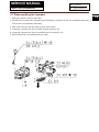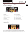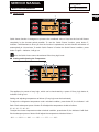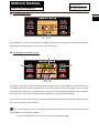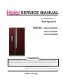
1
SERVICE MANUAL
Order No.Ref0906S012V0
Refrigerator
MODEL: HRF-633ISB2R
HRF-633ISB2B
HRF-663ISB2W
WARNING
This service information is designed for experienced repair technicians only and is not designed for use by the general public. It
dose not contain warnings and cautions to advice non technical individuals of potential dangers in attempting to service a product.
Product powered by electricity should by serviced or repaired only by experienced professional technicians. Any attempt to service
or repair the product or products dealt with in this service information by anyone else could result in serious injury or death.
Ƽ2009(HAIER ELECTRICAL APPLIANCES COR. LTD)
All right reserved. Unauthorized copying and distribution is a violation of lawDŽ
Haier Group
SERVICE MANUAL
Model: HRF-663ISB2R/B/W
Issue 200906
Rev. Ref0906S012V0
Contents
Table of Contents ·········································································································· 2
1. General Information ·································································································· 4
1-1. General guideline
4
1-2. Insurance test
4
1-3. How to read this Service Manual
5
2. Product Feature ········································································································ 6
2-1. Specifications
6
2-2. Main Functions and Features
8
2-3. External views
9
2-4. Product Dimensions
9
3. Disassembly ············································································································ 10
3-1. Remove the doors
10
3-1-1. Remove the kick moulding
10
3-1-2. Dismantles and install the upper decoration strip and cables
10
3-1-3. Dismantle and install the middle and lower hinge
10
3-2. Adjusting the Doors
11
3-3. Assembling the handles
11
3-4. Disassembling the switch
12
3-5. Removing the Air-Duct
12
3-5-1. Removal of fridge air-duct
12
3-5-2. Removal of freezing air-duct
12
3-6. Disassembling 13
3-7.Disassembling the 14
4. Control and display system ····················································································· 15
4-1. Control and display panel
15
4-2.Function adjustment
15
4-3. Sensor Distribution and Malfunction Codes
19
4-3-1. Sensor location description
19
4-3-2. Graphic display of the sensor location
20
2
SERVICE MANUAL
Model: HRF-663ISB2R/B/W
Issue 200906
Rev. Ref0906S012V0
5. Control principle of electronic component ···························································· 21
5-1. Air Escaper
21
5-2. Control Principle of the Fan motor
21
5-3. Defrost control principle
21
5-4. Ice maker work principle
22
6. System flow principle ······························································································· 23
6-1. Refrigeration flow chart
23
6-2. Perspective of the Refrigeration System
24
6-3. Diagram of icemaker water way
24
7. Circuit diagram·········································································································· 25
7-1. Circuit diagram
25
7-2. Main Control PCB diagram
25
8. Trouble shooting······································································································· 26
8-1. Common problems and solutions
26
8-1-1. Food in the fridge storage compartment is frozen
26
8-1-2. The buzzer beeps to alarm
26
8-1-3. No defrosting
26
8-1-4. Neither displaying nor starting when powering on
27
8-1-5. Poor freezing effect accompanied by loud noise
27
8-1-6.Common problems with icemaker system
28
8-2. Examination and Solutions for Other Problems
29
8-3. Checking flow chart
30
3
SERVICE MANUAL
Model: HRF-663ISB2R/B/W
Issue 200906
Rev. Ref0906S012V0
Chapter 1 General Information
1-1. General Guidelines
When servicing, observe the original lead dress. If a short circuit is found, replace all parts which
have been overheated or damaged by the short circuit. After servicing, see to it that all the protective
devices such as insulation barriers, insulation papers shields are properly installed. After servicing,
make the following leakage current checks to prevent the customer from being exposed to shock
hazards.
1) Leakage Current Cold Check
2) Leakage Current Hot Check
3) Prevention of Electro Static Discharge (ESD) to Electrostatic Sensitive
1-2. Insurance test
1. Check if there is any leak of current.
2. Cut out the power supply before the repair to avoid an electrical shock hazard.
3. In the case of a live-line test, insulating gloves should be worn to avoid potential electrical shock.
4. Confirm the rated current, voltage and capacity before testing with any kinds of instruments.
5. Watch if the upper door is open when you check something at a lower position.
6. Take out every part in the cabinet before moving the machine, especially things like panels (e.g. glass
shelf).
7. Please wear intact cotton gloves when repair any parts of the evaporator, so that scratches by the
sharp fins can be avoided.
8. If there is a breakdown with the refrigeration system, please surrender the machine to the service
center, else the leaked refrigerant may pollute the atmosphere.
9. The refrigerator use AC of 220V with a frequency of 50Hz.
10. A big fluctuation of voltage (exceed the range 187̚230V) may cause a start failure of the refrigerator,
a burn-out of the control panel and compressor, or an abnormal sound from the compressor in
operation. In this condition an automatic voltage regulator over 750W should be added.
11. Take care not to damage the supply line. Don’t yank at the line; pull the plug out gently from the
receptacle. Don’t press the line under the cabinet or step on it. Take care not to roll on or damage the
supply line when moves the machine from the wall.
12. In the case of leakage of inflammable gases like carbon monoxide, open the door and windows. Don’t
pull out or insert the plugs of the appliance.
13. Don’t touch the refrigeration surface of the freezing compartment when the refrigerator is in operation,
especially when your hand is wet, else you may be glued to the surface.
14. Pull out the plug of power supply during clearance or power outage. Wait at least five minutes to
resume the power supply in order to prevent damage to the compressor caused by continuous restart.
4
SERVICE MANUAL
Model: HRF-663ISB2R/B/W
Issue 200906
Rev. Ref0906S012V0
Photo used in this manual
The illustration and photos used in this Manual may not base on the final design of products, which
may differ from your products in some way.
1-3. How to read this Service Manual
1-3-1. Using Icons
The meaning of each icon is described in the table below:
Note:
A “note” provides information that is not indispensable, but may nevertheless be valuable to the
reader, such as tips and tricks.
Caution:
A “caution” is used when there is danger, through incorrect manipulation, may damage equipment,
loose data, get an unexpected result or has to restart (part of) a procedure.
Warning:
A “warning” is used when there is danger of personal injury.
Reference:
A “reference” guides to other places in this binder or in this manual, where we will find additional
information on a specific topic.
5
SERVICE MANUAL
Issue 200906
Rev. Ref0906S012V0
Model: HRF-663ISB2R/B/W
Chapter 2 Product Feature
6
2-1. SPECIFICATIONS
HRF-663ISB2R
HRF-663ISB2B
HRF-663ISB2W
1.
Model information
Product identification (Refrigerator/Freezer)
Refrigerator
Description of appliance
Side-by-side
Family type
American style
Type of appliance
(FS = free standing, BI = built-in)
FS
Type of cooling system (NF=no frost/ S=static)
NF
Climate class*
2.
SN/N/ST
Basic features
Energy efficiency class
A+
Freezer compartment star rating
*/***
Gross capacity
l
590
Total net capacity
l
500L
Net capacity refrigerator compartment
l
326L
l
174L
l
/
Freezing capacity / 24 hours
kg/24 h
10kg/24 h
Energy consumption / year
kWh/year
412.5
Energy consumption (EN153) per 24 h
kWh/24 h
1.13
Net capacity freezer compartment
(total)
Net capacity adjustable temperature drawer
Kind of coolant
(R134a/R600a)
R600a
Approvals (VDE / TÜV / IMQ / NF / ÖVE / DEMKO etc.)
TÜV
Certifications ( CE / ISO 9001/2 / LGA)
3.
GS/CE /EMC
Key features
Cooling system:
(K = Compressor / A = Absorption)
Number of compressor(s)
Defrosting Fridge / Freezer
Control system
4.
A=automatic)
(E = Electronic / M = Mechanical)
Fuzzy logic
K
n°
(M=manual
1
A
E
Y
Control panel
External control display
80g
Y
SERVICE MANUAL
Issue 200906
Rev. Ref0906S012V0
Model: HRF-663ISB2R/B/W
Fridge room Temperature range (from>to)
°C
3 to 7°C/
Freezer room Temperature range (from>to)
°C
-15 to -22°C
Super Cooling
(Fridge)
N
Super Freezing
(Freezer)
Y
Over temperature alarm
Red lamp / LCD-LED / Acoustic)
Control lamps
5.
Acoustic
(Green / yellow / red)
Y
Basics data
Voltage / frequency
220-240 V~/ 50Hz
Input power / mains fuse (intensity)
6.
200 / 2.2
Aesthetics
Door profile
(F = flat
/ R = rounded / S = streamline)
Handle
(External/Metal/Integrated)
F
External
Red%ODFN:KLWHglass
Available colours
7.
W /A
Interior description
Fridge compartment:
Shelves:
Number
(Total / adjustable)
Type
Colour
n° / n°
(gr=grill / g=glass / p=plastic)
G
(w=white / lb=light blue / g=green / t=transparent.)
Bottle holder / bottle(s)
3/3
t
n° / n°
4/4
n° / -
2/T
Crisper(s):
Number / colour
t = transparent, w = white
Shelf (on salad crisper)
(g=glass / p=plastic)
1/G
Door:
Storage rack(s)
(Total)
Type of rack(s)
Inside colour
n° / n°
g=glass / p=plastic
5
P
(w=white / lb=light blue / t=transparent.)
w
Freezer compartment:
Drawer(s)
Number / colour
n°
Adjustable temperature drawer
8.
n°
Shelf
number / p=plastic, g=glass ,W=wire
Door rack(s)
number / p=plastic, g=glass
n° / n°
3/G
4/P
Accessories
Interior light (fridge/freezer)
Special ice maker
W
(T=Twist, A = Automatic)
25/25
A
Eggs tray(s)
1
Adjustable feet
(front / rear)
n° / n°
2/0
Castors
(front / rear)
n° / n°
2/2
cm
200
cm
177*89*73.6
cm
67
Length of cable/incl. plug
9.
2/T
Product dimensions
Unit dimensions
Depth Without handle
( H / W / D)
7
SERVICE MANUAL
Issue 200906
Rev. Ref0906S012V0
Model: HRF-663ISB2R/B/W
10.
Depth with open door
cm
1188
Door open angle
n°
<135
Net weight
kg
145
cm
189.4*96*77
Gross weight
kg
155.0
40 ' Container load
pcs
28
40 ' HC Container load
pcs
28
kg
10.0
Packing dimensions & load ability
(H / W / D)
Packing dimensions
11.
Logistic / recycling information
Packing weight
Packing materials / Recycling symbols
Carton
12.
(RS)
RS
Kg
7
Service
Users instruction
(languages)
Multi-languages
2-2 Main Functions and Features
ƹ Automatic ice cube maker ,
ƹ Sliding glass shelves
ƹ Slim profile with spacious interior
ƹ The freezer compartment is equipped with a user-friendly frost-free system and manages to
freeze foods quickly and evenly
ƹ Temperature adjustment before defrosting
ƹ Automatic trouble indicator
ƹ Buzzer warning when door is open
ƹ Intelligent mode
8
SERVICE MANUAL
Model: HRF-663ISB2R/B/W
Issue 200906
Rev. Ref0906S012V0
2-3. External views
9
2-4. Product Dimensions
SERVICE MANUAL
Issue 200906
Rev. Ref0906S012V0
Model: HRF-663ISB2R/B/W
Chapter 3 Disassembly
10
3-1Remove the doors
Precautions During Dismantling and Installation of The Door
(1) Before removing the doors, please remove food from the shelves and the bottle guards. Then,
unplug the refrigerator power cord to avoid personal injury, product damage or property loss.
(2) During dismantling of the door, in order to avoid possible personal injury, product damage or
property loss, at least two adults are needed to perform the following operations.
(3) While lifting the hinges to separate it from the door, please take care to prevent the door from
falling forward.
3-1-1Remove the kick moulding
Remove the kick moulding,and then release
thewater coupler. Slide the kick moulding up to
Toe moulding
remove it,and then release the water coupler
while pressing on area(1) as shown in the
illustration.
Water coupler
3-1-2 Remove the Freezer door
1)Unscrew the hinge covers. Disconnect all
wires except for the grounding wire.
2)Remove the screws from the upper hinge
following the direction as indicated by Arrow(1).
Then remove the upper hinge following the
direction as indicated by Arrow(2).
3)Lift the freezer compartment door to remove it.
Wires
Next,lift the door enough to be able fully pull out
the water line.
3-1-3 Remove the Fridge door
Upper hinge
1) Loosen the hinge cover bolts, and then
Screw
remove the cover. Disconnect any wires
except for the grounding wire.
2) Remove the screws from the upper hinge
following the direction as indicated by Arrow
(1). Then remove the upper hinge following
the direction as indicated by Arrow (2).
3) Lift the refrigerator compartment door to
remove it.
Lower hinge
SERVICE MANUAL
Issue 200906
Rev. Ref0906S012V0
Model: HRF-663ISB2R/B/W
note: Reinstall the doors by reversing the removal steps.
3-2 Adjusting the Doors
If the freezer compartment door is lower than that of the refrigerator compartment, insert the wrench in
the groove of the left screw and turn it in the direction of the arrow until both doors are the same height.
(see pic1)
If the freezer compartment door is higher than that of the refrigerator compartment, insert the wrench
in the groove of the right screw and turn it in the direction of the arrow until both doors are the same
height. (see pic2)
3-3 Assembling the handles
1) Put the pothook of handle into the connector (as illustration 1); then pull down the handle hardly
while the top of handle and top of door are in the same level (as illustration 2).
2) Put the bolt into the right holes with the help of screwdriver (as illustration 3).
3) When you are disassembling the door handle, please operate as the opposite way of assembling.
Handle Holder
Handle
Connector
illustration 2
illustration 1
illustration 3
11
SERVICE MANUAL
Model: HRF-663ISB2R/B/W
Issue 200906
Rev. Ref0906S012V0
3-4 Disassembling the switch
1. To remove the switch pulls out it with a “_”type
screwdriver as shown in.
2. Disconnect the lead wire from switch.
3-5 Removing the Air-Duct
Unplug the refrigerator before removing the air-duct
3-5-1 Air-Duct assmebly in fridge
1. Unplug the power cord from the outlet;
2. Remove the fridge shelf;
3. Remove the lamp cover ;
4. The bulb can be replaced;
5. Loosening 2 screws fixed to ceiling of inner liner;
6. Pull out the electric damper, wind passage and the wind passage cover;
7. After replaced the disabled parts, assemble in reverse order of disassembly.
3-5-2 Air-Duct assmebly in Freezer
1. Unplug the power cord from the outlet;
2. Remove the freezer shelf;
3. Remove the lamp cover;
4. The bulb can be replaced;
5. Loosening 2 screws fixed the cover and pull out the top freezer air tower;
6. Pull out the bottom freezer air tower and unplug the sensor cable;
7. Pull out the freezer rack, unplug the fan motor cable and separate the fan motor, fan motor cover and
the rack;
12
SERVICE MANUAL
Model: HRF-663ISB2R/B/W
Issue 200906
Rev. Ref0906S012V0
8. Pull out the freezer air shutter;
9. Unplug the defrost sensor cable and replace it;
10. Assemble in reverse order of disassembly.
3-6 Disassembling the display panel
1. Unplug the power cord from the outlet;
2. Loosening 2 screws fixed the bottom of control panel assembly;
3. Unplug the display panel;
4. Loosening 4 screws fixed the control panel.
13
SERVICE MANUAL
Model: HRF-663ISB2R/B/W
Issue 200906
Rev. Ref0906S012V0
3-7 Disassembling the Icemaker
1. Unplug the power cord from the outlet;
2. Pull out the ice-crushed box assembly and loosening the screws from the ice-crushed box slide way; 3.
Pull out the ice-crushed box slide way;
4. Take out the ice box and then take out the ice box motor;
5. Loosening 4 screws from the ice maker support and put it out;
6. Loosening 2 screws from the ice-crushed motor box and put it out;
7. Disconnected the ice-crushed motor box cable.
14
SERVICE MANUAL
Issue 200906
Rev. Ref0906S012V0
Model: HRF-663ISB2R/B/W
Chapter 4 Control and display system
15
4-1. Control and display panel
G K
I
J
A
F
B
E
C
D
M N
O P
A---Fuzzy logic
I-----Ice maker indicator
B---Freezer temperature
J----- Quick freeze indicator
C---Lock function
K----- Freezer temperature indicator
D---Ice/Water
L------ Refrigerator temperature indicator
E--- Refrigerator temperature
M-----Lock function indicator
F----Quick freeze
N-----Water selected indicator
G----Fuzzy logic indicator
O-----Cubed ice selected indicator
H----Water filter indicator
P-----Crushed ice selected indicator
4-2. Function adjustment
Ƶ
Fuzzy logic function
G
A
If fuzzy logic is activated, the appliance will adjust inside temperature automatically according to
ambient temperature. Fuzzy logic is activated and inactivated by consecutive press of button A, then
Fuzzy logic indicator G will turned on and off.
SERVICE MANUAL
Issue 200906
Rev. Ref0906S012V0
Model: HRF-663ISB2R/B/W
Ƶ
Quick Freeze
J
16
F
Quick freeze function is designed to preserve the nutritional value of food as the food will freeze
completely in the shortest period possible. To use the ‘Quick Freeze’ function, press button F.
Indicator J will illuminate to show you that the function is operational, and this function will switch off
automatically in 3 hours later. To switch ‘Quick Freeze’ off under the ‘Quick Freeze’ condition, press
button F again – indicator J will go out.
Note: the Quick freeze cannot be activated if the fuzzy logic is set.
Ƶ
Setting and Adjusting the Temperature
G K
A
B
E
The appliance is preset at fuzzy logic, which can be inactivated by a press of Fuzzy logic button A,
indicator G will go out.
Setting and adjusting temperature as follows: (Fuzzy logic must be inactivated.)
To adjust the refrigerator temperature under unlocked condition, press button E, the indicator L will
flash. Each subsequent press of button E will adjust the temperature circled as follows:
5ć-4ć-3ć-7ć-6ć-5ć.
To adjust the freezer temperature under unlocked condition, press button B, the indicator K will flash.
Each subsequent press of button B will adjust the temperature circled as follows:
-18ć —— -20ć—— -22ć —— -15ć —— -17ć —— -18ć.
SERVICE MANUAL
Issue 200906
Rev. Ref0906S012V0
Model: HRF-663ISB2R/B/W
Ƶ
Ice cube/water select
17
D
N
O
P
The appliance is pre-set at crushed ice condition when the power supply is connected, indicator P
illuminates. Press the button D to choose the option you want.
Ƶ
Switching the icemaker on/off
I
A
F
N
O P
To close the ice maker, press and hold the button F and A for 3 seconds, indicator I and N comes on, it
is indicating that the ice maker has been turned off, this will shut off the water supply to the ice maker,
no cubed and crushed ice, Ice/Water button cannot be used for selecting between water, cubed ice
and crushed ice, but it will not affect the water dispenser, cool water is still available.
If you want to turn on the ice maker, press and hold the button F and A for 3 seconds, indicator I turns
off, ice maker restart to run as usual.
Note: 1) if indicator N, O and P cannot be selected, please confirm if the ice maker has been turned
off according to the above information.
2) the ice maker turns on when you re-connect the electricity supply.
SERVICE MANUAL
Issue 200906
Rev. Ref0906S012V0
Model: HRF-663ISB2R/B/W
Ƶ
Switching the refrigerator On/Off
18
L
E
To switch off the refrigerator, press and hold button E for 3 seconds, indicator L will disappear, but the
light will continue to illuminate.
To switch the refrigerator on again, press and hold button E, indicator L will reappear and the
refrigerator will begin to run as usual.
Ƶ
Locking and Unlocking the appliance
C
M
To lock the appliance, press and hold button C for 3 seconds under the unlock condition, indicator M
will light;
To unlock the appliance, press and hold button C for 3 seconds, indicator M will go out.
Note: Above functions can be used when the appliance has been locked.
Ƶ
Changing the water filter
H
D
SERVICE MANUAL
Issue 200906
Rev. Ref0906S012V0
Model: HRF-663ISB2R/B/W
When the water filter indicator light H comes on, it is indicating that the water filter requires changing
(approximately every 6 months). After finishing the change, press and hold button D for 3 seconds,
indicator light H will disappear.
Ƶ
Error Codes
In the event of an error occurring, the Freezer temperature indicator K and Refrigerator temperature
indicator L will show one of the following codes: E0, E1, E2, F1, F2, and F3.
The meanings of those error codes please find in chapter 4-3
Ƶ
Open door warning
If any door and home bar is left for more than 30 seconds the Door Alarm function will start to remind
you to close the door.
Ƶ
Control Function Display
30 seconds after the final press of any button, the display will be blank.
The display will illuminate
when the door is opened, or if you press any button.
Ƶ
Power-breaking Memorizing Function
When the refrigerator turns off as a result of a power surge, the state of the refrigerator before the
power break is memorized. Once restarted, this allows the refrigerator to operate with the programmed
default values as before the power break.
Note: this function is not suit for switching ice maker off and locking the refrigerator.
4-3 Sensor Distribution and Malfunction Codes
4-3-1 Graphic display of the sensor location
()
(5)
(ICE)
(D)
(F)
(5)
19
SERVICE MANUAL
Issue 200906
Rev. Ref0906S012V0
Model: HRF-663ISB2R/B/W
4-3-2 Error code display
NO
Item
Error Code
Meanings of Code
1
Normal
Display
No
2
Refrigerator R1 sensor malfunction
F1
R1 SNR short circuit or open circuit
3
Refrigerator R2 sensor malfunction
F2
R1 SNR short circuit or open circuit
4
Ambient temperature Sensor malfunction
F3
RT SNR short circuit or open circuit
5
Freezer sensor malfunction
F4
F SNR short circuit or open circuit
6
Defrost sensor malfunction
F6
D SNR short circuit or open circuit
7
Icemaker sensor malfunction
F7
ICE SNR short circuit or open circuit
8
Signal transmit component
E0
9
Freezer fan motor malfunction
E1
No single send out more than 30 seconds
10
Cooling fan motor malfunction
E2
No single send out more than 30 seconds
11
Defrost Heating System error
Ed
centigrade after temperature rise more than 2
No reflect when setting ,between display PCB
and Power PCB no signal transmitted over 2 min
Defrost sensor temperature can’t reach to 7
hours
20
SERVICE MANUAL
Model: HRF-663ISB2R/B/W
Issue 200906
Rev. Ref0906S012V0
Chapter 5 Control principle of electronic component
5-1. Air Escaper
(1) The refrigeration air escaper is controlled with the fridge storage temperature sensor R
SNR.
(2) The air escaper is closed from the beginning of defrosting until 15 minutes after the
defrosting is finished.
(3) Upon initial powering on or resetting of the control panel, the air escaper conducts a
close-and-open cycle before acting according to the control conditions in item (1).
(4) The air escaper will be forced to conduct an open-and-close cycle if it has been closed for 1
hour. After that, its closing/opening will be controlled by R SNR.
(5) The air escaper will automaticlly close when fridge door have been opend over 2 minutes.
5-2. Control Principle of the Fan
The freezer fan is controlled by the control panel according to the following conditions. The DC
fan’s rotation speed is regulated with PWM mode and the AC fan operates directly.
(1) Upon initial powering on,the freezer fan motor will running before the air escaper in fridge first
close.
(2) When the fridge storage compartment door is opened, the freezer fan will run and the refrigeration
air door will open. After 2 minutes, the refrigeration air door will close;
(3) When the freezer storage compartment door is open, the freezer fan will stop running;
(4) Conditions for judging LOCK of the freezer fan: If the rotation speed of the fan is less than
300RPM or the fan does not run and the state has persisted for over 30 seconds, a freezer fan
malfunction will be displayed. Normal display will be recovered after it becomes normal.
Otherwise the freezer fan malfunction will persist.
5-3. Defrosting Control Principle
(1) A defrosting cycle will be started once the compressor has been operated for 8 hours
accumulatively. It will stop defrosting when the defrosting sensor detects a temperature over 7ºC.
(2) The compressor stops and the refrigeration air door is closed during defrosting.
(3) After initial powering on or resetting of the control panel, it will start the first defrosting cycle after
the compressor has operated for 4 hours accumulatively. If the super freezer function is used,
defrosting will be start after 7 hours compressor running.
(4) It may enter the defrosting state when the defrosting sensor is malfunctiony (short-circuit or
open-circuit). In this case, it will exit the defrosting state after 30 minutes.
21
SERVICE MANUAL
Issue 200906
Rev. Ref0906S012V0
Model: HRF-663ISB2R/B/W
5-4. Icemaker working principle
(1) Once the appliance powered on, and the temperature of ice maker sensor drop to -12ć, the ice
maker will initialize automatically then begin to pour water in.
(2) After water have poured in one hour, the motor will rotate to start ice pushing in 2 minutes
when the temperature of ice maker sensor drop to -12ć;If the temperature is higher than -12ć,
the motor will keep waiting to push the ice cube until temperature drop to -12ć.
(3) The motor will wait 1 hour to push ice when detect the ice store box is full.
(4) The ice maker will rotate every 100 minutes if the ice make sensor is error
(5) After every ice-pushing, the motor will adjust ice box horizontally, then the water valve which is
controlled by relay on main control PCB will start to pour water in.
(6) Water inlet quantity can be controlled through DIP S/W Control buttons on the main control PCB
on any power on/off condition. If the adjustment is under the water inlet condition, the water
valve will execute the time before adjustment, new inlet time will be executed next time.
No
DIP S/W Control
Water inlet time
Remark
S1
S2
S3
1
OFF
OFF
OFF
6.0 seconds
Adjust the water inlet time
2
ON
OFF
OFF
3.5 seconds
according to the different
3
OFF
ON
OFF
4.0 seconds
water pressure.
4
ON
ON
OFF
5.0 seconds
5
OFF
OFF
ON
5.5 seconds
80-120ccDŽ
6
ON
OFF
ON
6.0 seconds
7
OFF
ON
ON
7.0 seconds
8
ON
ON
ON
8.0 seconds
(7) If cool water valve and ice maker valve both need to inlet water, water will be supplied to cool water
22
SERVICE MANUAL
Model: HRF-663ISB2R/B/W
Issue 200906
Rev. Ref0906S012V0
valve first and next comes to ice maker, if cool water valve needs water when ice maker valve is inlet
water, both two valve will be supplied water at the same time.
Chapter 6 System flow principle
6-1. Refrigeration flow chart
Principle diagram and description of the refrigeration cycle
The refrigerant is compressed in the compressor, from there, it enters the dry filter, de-dewing tube,
and the condenser, and goes into the evaporator after being throttled and decompressed in the
capillary tube. Finally, it returns to the compressor through the air return tube.
Principle diagram of the refrigeration cycle:
23
SERVICE MANUAL
Issue 200906
Rev. Ref0906S012V0
Model: HRF-663ISB2R/B/W
6-2. Perspective of the Refrigeration System
24
ķ
ĸ
Ĺ
ĺ
Ļ
ļ
Ľ
ľ
Ŀ
ŀ
6-3 Diagram of icemaker and dispenser waterway
!
"#&&&&
$ % SERVICE MANUAL
Issue 200906
Rev. Ref0906S012V0
Model: HRF-663ISB2R/B/W
Chapter 7 Circuit diagram
25
7-1.Circuit diagram
D spenser LED amp
7-2. Main control PCB diagram
Main control PCB
Pu ple Black
V GND
REF a r damper
Wh te G ay G ay Wh te Wh t ran e ink la k l ck m t
ed
REF air damper
mo or
l e
REF sensor
ďBe owĐ
REF sensor
ďupĐ
REF air damper
heater
Dispenser switch
e lo
M
REF door
sw tch
Null line
Ice ou let cover valve
Wh t
Empt
Empt
Bl e
Black
&21
&21
ce maker water n et heater
Cool water wa er inlet
Water valve Ice maker wa er inlet
Ice cube choose valve
Ice pusher mo or
FRZ lamp
Ice maker
Ice maker
M
mo or
la k e lo row m t m t ray ray ed
Wh t
lue
Hall switch
Ice maker
test switch
Ice maker senso
Wh te
Wh te
lue
rown
D sp ay panel
reen
ed
rang
Water outlet
Cover heater
Pink
Br wn
Defrost heater (L)
Null l ne
Defrost heater (N)
Dispenser heater
Red
M
REF room lamp Pu pl
&21
G een ray ran e rang ed ed la k lack l e
Purple
urple
Red
M
M
Empty
Blue
Blue
e low
Blue
ray
rown
&21
Null l ne
Nu l ine
Coo ing an
mo or
rang
urple
ky blu
R dWh
Blue
B u Wh
Red
&21
Freezer fan
mo or
l ck
&21
&21
Amb ent sensor
rown
Blue
Purple
FRZ door
switch
Defrost senso
FRZ sensor
&21
&21
Blue Red
Blue B own
Frequency converter PCB
Frequency conver er PCB
connect cab e
Compressor connect cable
F lter
Blue
B own
Brown
B ue
B ack
Yel owGreen
Compressor
M DJQHWLF ULQJ
Ye low/G een
B ue Br wn
Power cab e
SERVICE MANUAL
Model: HRF-663ISB2R/B/W
Issue 200906
Rev. Ref0906S012V0
Chapter 8 Trouble shooting
8-1. Common problems and solutions
8-1-1 Symptom: food in the fridge storage compartment is frozen
Check:
1) Verify that the temperature in the fridge storage compartment is too low and the food is frozen there;
2) Remove the decoration piece of the refrigeration air-duct. Detach the 2 screws and take out the air
door-foam assembly. Press the “Refrigeration OFF” button to see if the air door closes
automatically. If the air door closes tightly, continue to next step. If the air door does not close
normally, continue to step 6).
3) Disconnect the connection wires of the air door and the LED lamps. Take out the air door-foam
assembly. Tear the adhesive tape wrapped around the foam and separate the foam. Check if the
seal between the air door and the foam is tight.
4) If the seal is tight, check if the fridge storage temperature sensor R1 is OK.
5)If the sensor R1 is OK, then the main control panel is probably malfunctioning.
6) If the wiring of the air door is OK, check the circuit from the connector of the main control panel to
the connector in the cabinet. If there is no problem in this circuit, the air door is malfunctioning.
Solutions:
1) If the seal between the air door and the foam is found to be not tight, please affix seal strip on the
interface between the air door and the foam;
2) If the sensor R1 is malfunctioning, please replace it with a new one;
3) If the main control panel is malfunctioning, please replace it with a new one;
4) If the connector of the air door is connected with reverse polarity, please reconnect it correctly;
5) If the air door is malfunctioning, please replace it with a new one.
8-1-2 Symptom: the buzzer beeps to alarm
1) Test across pin 4 and pin 3 of CN1 on the main control panel. The 2 pins should be switched to
conduction when the door is closed and disconnected when the door is open.
2) If pin 4 and pin 3 of CN1 are disconnected in both cases, please remove the front decoration strip to
see if the door switch is still in the slot.
8-1-3 Symptom: no defrosting
Check:
1) Activate the forced defrosting function by double pressing the button on the main control panel.
Then, check if the temperature of the defrosting heating wire is rising.
If the temperature of the heating wire does not change, remove the fan cover plate to check if all
the connectors are connected properly and test if there is 220V voltage output across the
terminals of the heating wire.
26
SERVICE MANUAL
Model: HRF-663ISB2R/B/W
Issue 200906
Rev. Ref0906S012V0
2) Measure the resistance of the heating wire with a multimeter. It should be around 345.
3) Measure the resistance of the defrosting fuse. If it is zero, the fuse is OK. If it is infinite, the fuse is
malfunctioning.
4) If no malfunction is found in the above checks, please test the defrosting temperature sensor with a
multimeter.
8-1-4 Symptom: neither displaying nor starting when powering on
Check:
1) Check if the power supply is connected properly.
2) Remove the main control panel and examine its back side carefully to see if there are solder skips
or open soldering;
3) Check if the connector of the freezer door hinge is connected properly.
4) Verify the display panel to see if the refrigerator is in OFF state. If so, press and hold the button on
the power board for 3s to turn it on.
Solutions:
1) If there is dry soldering or open soldering on the control panel, resolder it with an electrical iron.
2) If any connector is not connected properly, replug it firmly.
3) Press and hold the button on the power board for 3s to turn the refrigerator on.
8-1-5 Symptom: poor freezing effect accompanied by loud noise
Check:
1) Check if there is apparent abnormal sound in the freezer storage compartment. Remove the fan
cover plate, close the refrigeration air door (and the icemaker air door), and check if the freezer fan
is operating normally. (The fan does not operate when the refrigeration air door is open. Please first
eliminate the possibility of improper installation of the door on-off)
2) If the freezer fan does not run, remove it and check if its connector and the cabinet connector are
connected properly. Test if there is approximately 12VDC voltage across pin2 and pin 3 of CN4. If
there is no 12VDC voltage, the main control panel can generally be determined to be
malfunctioning. If there is 12VDC voltage, the freezer fan can generally be determined to be
malfunctioning.
3) If the fan rotates abnormally, the fan is malfunctioning.
Solutions:
(1)If there is apparent abnormal sound in the freezer storage compartment, check if the fan base is
firmly fixed, if the fan vanes are installed properly, and if they intervene with the wires. If any of these
problems is found, please remove the fan and reinstall it properly.
(2)If the fan connector is not installed properly, disconnect the terminals and reinstall the connectorDŽ
(3)If the main control panel or the fan is malfunctioning, replace the malfunctioning one with a good
spare part.
27
SERVICE MANUAL
Issue 200906
Rev. Ref0906S012V0
Model: HRF-663ISB2R/B/W
8-1-6 Common problems with icemaker system
1. Water inflow adjustment
Adjust set button. When inputting water time is flashing (input water time is only available when
icemaker is open), press OK button for time adjustment. Just press up and down button to adjust the
time. If ̛8mm, time adjustable range circles between 2 to 7 seconds and every adjustment shall be
0.5s increasing or decreasing. When water pressure is between 1.5-7.5bar, input water time can be
adjusted to 4s or 4.5s, while input water volume is about 80g and default input water time is 4s.
2. Ice is too small
Ice is too
small
Does water pressure meet
the requirements?
Adjust water
pressure
Adjust input water time
1. Water leakage of freezer storage compartment
a)
Check whether input water time of the icemaker is too long, as 4s or 4.5s input water time has
a water flow at a volume of 80g. If time is too long will cause ice box to store too much water.
b)
Ice in ice box is frozen, can’t be removed. Just clean the ice box.
c)
Check whether ice box is installed in icemaker, if not, just install the ice box.
2. Icemaker doesn’t make ice
a)
Check whether icemaker function is available or not, if not, activate the function via display
panel.
b)
Check whether pipes connected to water tap are open or not open, if not, open the pipes.
c)
Check whether water valve is frozen (check by icemaker waterway testing function), if yes,
just defrost the water valve.
d)
Check whether ice detection level is stuck, if yes, just make the level unstuck.
e)
Check whether door of the icemaker is open or not closed tightly; close the door well.
f)
Check whether the temperature in freezer storage compartment is available for ice making
(suitable temperature is below -12ć).
28
SERVICE MANUAL
Issue 200906
Rev. Ref0906S012V0
Model: HRF-663ISB2R/B/W
8-2 Examination and Solutions for Other Problems
Problems
Causes
Water/moisture/frost in the refrigerator
Moisture accumulates
z Hot and moist climate.
z
on the refrigerators
z The door is not closed
inner walls
tightly
z
z The door is opened too
frequently or for too long
time
z
Water/moisture/frost on outside surface of the refrigerator
Moisture accumulates
z Damp climate
z
on the refrigerator’s
z The refrigerator door is
outside surface or
not closed tightly. This
z
between two doors
causes mixing of the cold
air in the refrigerator with
the warm air outside it
Refrigerator operation
The compressor does
z The refrigerator is in
z
not work
defrosting cycle.
z The refrigerator is not
z
plugged into a power
outlet.
z
z The refrigerator is in OFF
state.
The fridge storage
compartment does not
work
The refrigerator runs
frequently or runs for
too long period
z
The air door cable is not
connected properly.
z
The fan does not work
z
The fridge storage
compartment is turned
off
z
z
z
z
z
z
z
z
z
The indoor or outdoor
temperature is high
The refrigerator has been
powered off for a period
of time.
The automatic icemaker
is operating.
The door is opened too
frequently or for long
periods.
The door of the fridge /
freezer storage
compartment is not
tightly closed.
The temperature setting
for the freezer storage
compartment is too low
The door gasket of the
z
z
z
z
z
z
z
z
Solutions
Accumulation of frost and moisture
accelerate in such climate.
Make sure the refrigerator is level and there
is no food or container interfering with the
door
Do not open the door so frequently
It is normal in damp climate. The moisture
will decrease when the humidity drops.
Make sure the refrigerator is level and there
is no food or container interfering with the
door
It is normal for an automatic defrosting
refrigerator.
Verify the plug is plugged in the socket
firmly.
Press the “Power” button for 3 second or
more to restart the refrigerator or turn the
knob from OFF to temperature selection
position.
Check if the air door cable is not connected
properly and install it correctly if not so.
Verify that the air door acts normally with
the Fridge ON/OFF key on the display
panel
The fan does not work while the
refrigeration air door is open. Please check
if the door on-off behind the front decoration
strip is installed properly. Reinstall it
correctly if not so.
Turn on the fridge storage compartment
manually
In this case, it is normal for the refrigerator
to run longer.
Normally, it takes 8 to 12 hours for the
refrigerator to totally cool down.
Icemaking process makes the refrigerator
to run longer.
Warm air enters the refrigerator and causes
it to start frequently. Please do not open the
door so frequently.
Make sure the refrigerator is level place and
there is no food or container interfering with
the door.
Set the temperature higher until satisfactory
refrigerator temperature is obtained. It takes
24 hours for the refrigerator temperature to
become stable.
Clean or replace the door gasket. Leakage
gap of door gasket can cause longer
29
SERVICE MANUAL
Issue 200906
Rev. Ref0906S012V0
Model: HRF-663ISB2R/B/W
z
Too high temperature
Too high temperature
in the fridge/freezer
storage compartment
z
z
z
z
z
The temperature in the
freezer storage
compartment is too
high while the
temperature in the
fridge storage
compartment is OK
The temperature in the z
fridge storage
compartment is too
high while the
temperature in the
freezer storage
compartment is OK
Bad odors in the refrigerator
The inside of the
z
refrigerator is dirty
z
If you hear...
Beeps
z
z
Abnormal sound
z
z
fridge/freezer storage
compartment is dirty,
worn, cracked or
mismatched.
The condenser is dirty.
running time of the refrigerator in order to
maintain desired temperature.
z
Clean the condenser.
The door is opened too
frequently or for too long
periods of time
Temperature is set too
high
The door is not closed
tightly
The condenser is dirty
The temperature is set
too high
z
Warm air will enter the refrigerator
whenever the door is opened. Try to open
the door as infrequently as possible.
Reset the temperature.
Make sure the refrigerator is on a level
surface and there is no food or container
interfering with the door.
Clean the condenser.
Set the freezer temperature lower. It takes
24 hours for the temperature of the
refrigerator to become stable.
The temperature is set
too high
z
Set the fridge temperature lower. It takes 24
hours for the temperature of the refrigerator
to become stable.
The inside of the
refrigerator needs
cleaning
Food with strong odor is
stored in the refrigerator
z
Clean the internal of the refrigerator
z
Wrap the food tightly.
The fridge storage
compartment door is
open
The temperature in the
freezer storage
compartment is too high
z
Close the door or silence the alarm
manually
z
The alarm is normal when it is first started
due to relatively higher temperature.
The refrigerator is not
located on a level
surface
The refrigerator touches
some object around it
z
Adjust the feet to level the refrigerator.
z
Remove objects around it.
z
z
z
z
Slight sound similar to
that of flowing water
z
It is the sound of the
refrigerating system
z
Normal.
Heating of cabinet
z
The de-dew tube is
de-dewing
z
It is a process to prevent dewing. It is a
normal phenomenon.
30
SERVICE MANUAL
Issue 200906
Rev. Ref0906S012V0
Model: HRF-663ISB2R/B/W
8-3. Checking flow chart
31
Com pressor
doesnÿ t start
Y
W hether lighting
and display system is
normal
N
Trouble of lighting and display system
Y
Adjust the grade according to fact
Y
Compressor is open circuit or short
circuit
Y
Inner trouble of com pressor
Y
W hether the
grade of therm ostat is
on 0
N
W hether the
resistance of compressor is
infinite or 0
W hether the
starting current is
about 5A
N
W hether PTC starterᢃ
resistance between running jack
and starting jack is 16-50 O
N
If it is infinite or 0, then the starter is
out of work.
N
Heat protector is out of work
Y
M easure whether
two ends of heat protector
is through
Y
W hether the finger
of multimeter swing to 0 quickly
and then swing back slowly
when m easuring two
poles of capacitance
N
Change for a new compressor
N
Capacitance is out of work
Y
W hether
compressorᢃ pin is tight,
contact
is good
N
Insert again, electrify and test
N
Main control board is out of work
Y
W hether input
and output voltage of main
control board is normal
Y
W hether each
contact of main control board
is norm al
Tighten each
contact and test machine
again
Com pressor doesnÿ t start
sometim es because the
tem perature in case is
between starting and stop
temperature, should pay
attention when do test
Adjustm ent of thermostat
Temperature of
environm ent
>30ć
1-3 grade
16-30ć
3-5grade
<16ć
5-7grad
Sincere forever
Haier Group
Haier Industrial Park, No.1, Haier Road
266101, Qingdao, China
http://www.haier.com