1
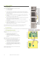
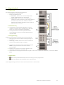
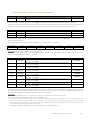
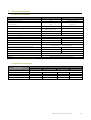
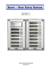
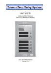
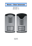
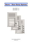
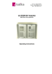
Ulydor User and Service Manual
Version 1.0
Table of Contents
1
INTRODUCTION ................................................................................................................................ 4
1.1
1.2
1.3
1.4
2
FEATURES ...................................................................................................................... 4
MODULES ...................................................................................................................... 5
ENCLOSURES AND HOODS .................................................................................................. 5
ACCESSORIES .................................................................................................................. 5
MECHANICAL INSTALLATION............................................................................................................. 6
2.1
2.2
2.3
2.4
2.5
2.6
3
SURFACE MOUNT ENCLOSURE FITMENT ................................................................................. 6
FLUSH MOUNT ENCLOSURE FITMENT ..................................................................................... 6
MODULE MOUNTING FRAME ASSEMBLY ................................................................................ 6
MODULE FITMENT AND REMOVAL ........................................................................................ 7
NAME TAG FITMENT ......................................................................................................... 7
COVER FRAME FITMENT AND REMOVAL ................................................................................. 8
CONTROL MODULES ......................................................................................................................... 9
3.1
3.2
3.2.1
3.2.2
3.2.3
3.2.4
3.2.5
4
BUTTON MODULES ......................................................................................................................... 12
4.1
4.2
4.3
5
OVERVIEW ..................................................................................................................... 9
CONNECTIVITY................................................................................................................. 9
Power................................................................................................................................................................................. 9
Exit button ....................................................................................................................................................................... 10
Expansion peripheral Component Interconnect (PCI) for extra buttons & keypad .......................................................... 10
Analogue line connectivity ............................................................................................................................................... 10
Relays .............................................................................................................................................................................. 10
OVERVIEW ................................................................................................................... 12
CONNECTIVITY............................................................................................................... 12
PROGRAMMING OVERVIEW .............................................................................................. 12
KEYPAD MODULE ........................................................................................................................... 13
5.1
5.2
5.3
5.4
OVERVIEW ................................................................................................................... 13
CONNECTIVITY............................................................................................................... 13
PROGRAMMING ............................................................................................................ 13
OPERATION .................................................................................................................. 13
6
DOOR ENTRY SYSTEM OPERATION .................................................................................................. 14
6.1
6.2
SIGNALLING OVERVIEW .................................................................................................... 14
MODE OF OPERATION ..................................................................................................... 15
6.2.1
Visitor access ................................................................................................................................................................... 15
6.2.2
Staff access ...................................................................................................................................................................... 15
6.2.3
Day & Night/Groups ........................................................................................................................................................ 15
7
PARAMETER PROGRAMMING ......................................................................................................... 16
7.1
7.1.1
7.1.2
7.2
8
8.1
8.2
8.3
8.4
8.5
8.6
8.7
8.8
8.9
PROGRAMMING WITH PHONE ........................................................................................... 16
Entry into the programming ............................................................................................................................................ 16
Parameter programming ................................................................................................................................................. 16
PROGRAMMING WITH A PC.............................................................................................. 16
DESCRIPTION OF PROGRAMMABLE PARAMETERS ........................................................................... 17
DIRECT DIALLING – MEMORY ............................................................................................ 17
RELAYS ........................................................................................................................ 18
BASIC PARAMETERS ........................................................................................................ 20
TIME PARAMETERS ......................................................................................................... 22
SYSTEM PARAMETERS ..................................................................................................... 25
PARAMETER SETTING HANDS FREE ..................................................................................... 26
TIME PROGRAMME – AUTOMATIC SWITCH DAY/NIGHT AVS .................................................... 29
BASIC SETTING AND DELETION ........................................................................................... 30
END OF PROGRAMMING .................................................................................................. 30
9
9.1
9.2
TECHNICAL PARAMETERS................................................................................................................ 31
ELECTRICAL PARAMETERS ................................................................................................. 31
MECHANICAL DIMENSIONS ............................................................................................... 31
Ulydor User and service manual
3
1
Introduction
1.1 Features
Thank you for purchasing this Ulydor product.
This new range is a continuation of the popular ‘Standard’ and ‘Anti-Vandal’ range of Ulydor products and has been
designed to add extra functionality whilst maintaining many of the programming parameters that are familiar to
existing users.
As with the previous Ulydor versions, the modular system is built by starting with a Zero, One or Two button controller
and adding extra modules to suit your requirements.
It is now possible to extend the controller with anything from 4 to 99 buttons.
Basic functions of the new AVS line
Continues the modular approach allowing for easy customisation and expansion
Switchable LED backlit name tags
Two independent relays with 8 setting regimes for an additional bell, gradual door opening etc.
Electronic volume control without the need to open the front cover
Programmable tone detection for call disconnection or repeat calls
Integrated real time clock for automatic day/night switching (AVS)
Programming via phone using DTMF tones or software using Kalika USB2PC cable (available separately)
24 digit telephone numbers including * # Flash and Pause
Voice communication is powered from a telephone line
Impulse and tone (DTMF) options
Option to prolong a call with * or #
Option to connect two independent locks to open doors
Two codes to disconnect the Door Entry System from a phone
Two codes to open doors from the phone for 1-impulse and two codes for 2-impulse
3 x 6 code locks for each relay (password from door buttons)
Option to connect an exit button
Option to disconnect a call by the repeated pressing of a button
Option to switch on a ‘baby call’ regime (no number dialling)
Option to switch on a regime to suppress the DTMF connection from the microphone
Option to switch on a ‘ticking’ sound into a call to announce another call
Option to switch on acoustic signalling for relay connection
Option to set the number of rings before connecting a call
Programmable parameters for tone options Flash length and Pause length
Programmable parameters for acoustic signalisation
Programmable parameters for tone detection
Easy setting hardware with the help of a DIP switch
Integrated regulated heating of the PCB
Unit can be earthed for better protection against static electricity
1.2 Modules
UC0 0 Button Controller
UC1 1 Button Controller
UC2 2 Button Controller
C4 4 Button Master
M4 4 Button Slave
UCK 12 Button Keypad
IPC IP Colour Camera
LSPK Loudspeaker
BLK Blank
NNM Name & Number
RFIDL-R Standalone Prox
1.3 Enclosures and hoods
Modules are installed inside either surface or flush mount enclosures.
When installing flush mount outside, we recommend adding an exterior weather hood. Examples show AVS enclosures
Surface mount enclosure
Flush mount enclosure
Exterior weather hood
1.4 Accessories
LIK-EX-M
Mag lock kit for external door
LIK-INT-M
Mag lock kit for external door
USB2PC
USB Programming lead
Ulydor User and service manual
5
2
Mechanical Installation
2.1 Surface mount enclosure fitment
Screw the surface mount box to the wall with the provided screws and plugs as shown with the top of the enclosure
being between 1.55m and 1.60m from ground level.
Tip: For additional weatherproofing we recommend a bead of silicon be applied to the left, top and right edges of the
enclosure where it meets the wall.
2.2 Flush mount enclosure fitment
Flush mount enclosures are made up of back boxes that are fixed into the wall/cavity with the front edge slightly under
the surface. The module mounting frame is then screwed to the back box with the cover frame attached to it
completing the assembly.
Note: When fitted outside, we recommend fitting an exterior weather hood between the back box and module
mounting frame.
2.3 Module mounting frame assembly
The bottom part of the module frame is hinged to allow easy access to the modules. Screw on the bottom part of the
frame through the hinge noting the orientation. The top of the module mounting frame is affixed with one screw.
6
Ulydor User and service manual
2.4 Module fitment and removal
Refer to Electrical Connection section for recommended fitting order of modules
Note: Take care when inserting and removing modules so as to avoid damage to their alignment pins on each corner.
2.5 Name tag fitment
There are 2 lugs on the right side of each module. Gently pull the
lugs back and lift the front cover off as shown.
Paper tags are held to the front panel with a plastic holder. Use
the clear plastic holder if you are using back lighting to illuminate
the tag.
The tag dimensions are 55 x 14.5 mm.
Tip: A Dymo Label maker is ideal for creating neat professional
tags www.dymo.co.uk
To replace the front cover, reverse the removal procedure, being
careful to insert the two locating lugs on the left correctly.
Note: Be careful of the rubber seal of the microphone when
changing the name tags on the controller module as improper
assembly may affect the acoustics.
Ulydor User and service manual
7
2.6 Cover frame fitment and removal
The cover frame is affixed and removed with 2 x supplied screws (B) as shown that screw into the head of the module
frame screw (A).
Tip: Ensure correct alignment of screw (B) before tightening to avoid stripping the thread.
8
Ulydor User and service manual
3
Control modules
3.1 Overview
There are three types of control module, one of which MUST be chosen for each installation:
• UC0 – Zero button control module
• UC1 – One button control module
• UC2 – Two button control module
3.2 Connectivity
1. Microphone
2. Expansion connection for additional modules
3. PC Connection for programming/upgrading via
software using USB2PC cable
4. LED indicator
5. Speaker
6. Power connection 11-24V DC or 10-18V AC (the
polarity is not important)
7. Relay connections - Galvanically isolated, load is
max. 48V, max. 1,5A
8. Exit button connection
9. Analogue telephone line connection (the
polarity is not important)
10. Earth connection - Protects door entry and
phone system from static electricity
11. DIP switch
12.
DIP switch settings:
1. Service – for use when the programming code is forgotten. Forces incoming call into programming
mode where a new code can be set. MUST be switched off again for normal operation
2. Motherboard Heating – Helps prevent condensation build-up during changeable temperatures
3. Internal power supply - Always 3 and 4 together
4. Internal power supply - Always 3 and 4 together
Power supply is used from terminal 12V (6) and is used for 2 reasons:
When using Relay regime 7 or 8 Constant connection or disconnection of a relay is possible only
with internal power supply. Don’t forget to also set parameter 64.
Connection of the door entry system to the phone line switchboard that has problem with power
supply after switching on (Siemens)
For powering exit button circuit
5. Back lighting On/Off
3.2.1
Power
The 12V power supply can be 10-18V AC or 11-24V DC. Polarity is unimportant.
The maximum load from a 12V supply is 250mA.
It is possible to use the same power supply to power up an electronic lock, but it is recommended that 12V/1A is used
such as the Kalika PSU/3-1.
Supply voltage on the terminal (6) is necessary for the following functions:
• Relay control
• Motherboard heating - DIP 2 switches on, regulation of current according to voltage and temperature
• Name tag back lighting (DIP 5 switches on)
• Internal power supply of door entry system electronics (DIP 3 & 4) for relay regimes 7 and 8 (parameter 64)
and Powering up the exit button circuit
Ulydor User and service manual
9
3.2.2
Exit button
The exit button is used for relay control. On each relay it is possible to set up a switch on one or on two impulses.
A 12V power supply must be connected to the terminal (6).
3.2.3
Expansion peripheral Component Interconnect (PCI) for extra buttons & keypad
This PCI enables you to connect additional buttons (up to 99) including a keypad. As well as data, the PCI is also used to
supply the additional modules with power for backlighting.
3.2.4
Analogue line connectivity
The basic function (connection and disconnection of a call) only requires an analogue telephone line connection
connected to terminal (9). The polarity of the phone line is unimportant.
Parallel connection with another door entry system or phone is NOT recommended
3.2.5
Relays
You will need to connect a 12V power supply to terminal (6) for the relays to function correctly. The door entry system
is designed so that all parts are galvanically separated to avoid interaction between the telephone line and power
supply circuit.
Examples of relay connection are shown on the following page.
This is not an exhaustive list of possible connections but they illustrate how to connect each circuit
1.
2.
3.
4.
5.
6.
Basic connection – 2 electric locks and the potential to control two doors independently (relay regime 1 and 2 m=1)
or the gradual opening of a door (relay regime 2 - m=5
Two sources – the potential to use two power sources, one for the Ulydor and a second for an electric lock. Electric
lock 2 is connected inversely (i.e. emergency fire door).
Combination of a door with an electric lock and a sliding gate.
Extends the previous example to two doors with gradual opening (this function is set in Time Relay - external
module).
Combination of an electrical lock and an add-on bell. The relay for an add-on bell can be in regime m=4 (each
button switches on for a set length of time) or in regime m=6 (switches on from one pre-set button for a set length
of time).
Light switch m=3 (i.e. lighting to the building) with relay 1. Relay 2 – controls, for example, heating according to
day/night regime m=8. It requires an external power supply (DIP 3 and 4) and would require a contactor (Ulydor
cannot switch 230V!).
Further programming instructions can be found in the section 7 of this manual.
10
Ulydor User and service manual
Under no circumstances use 120V or 230V direct current (DC)!
This can be solved by the use of contactors (power relays) as per example 6
Ulydor User and service manual
11
4
Button modules
4.1 Overview
There are two types of four button extension module:
• C4 - Master module
• M4 - Slave module
The C4 module has an eight button capacity but only has four physical
buttons fitted. These four additional physical buttons are provided by the
M4 module below it
M4 modules MUST be hardwired to C4 modules and will not function in
isolation
To maintain correct button order, an M4 MUST be placed between two
C4 modules e.g. C4, M4, C4, M4, C4 etc.
Control modules are always at the start of a Data Bus that communicates
with any C4 or single UCK modules fitted
This is achieved using a flat cable which also carries the voltage for
backlighting
Every C4 and UCK module fitted to the control module has a sequential
‘position’ on the Data Bus
When a UCK is fitted, the ‘position’ it occupies is required when
programming the control module
The image shows the correct order of modules. Note that the UCK occupies
position 2 and the C4, being first in the Data Bus, occupies position 1.
4.2 Connectivity
The image below illustrates the connectivity between a C4 and M4 viewed from the rear of the modules.
4.3 Programming overview
Programming each button is acheived by one of two
methods:
1. Dialling into the control module and
programming via DTMF tones
2. Connecting a USB2PC cable to the control
module’s PC connector and programming via
software
Tip: The buttons on a button module can be used as an
access code without a UCK keypad being fitted.
Count the number of buttons physically fitted
including those on the control module e.g. 5
Create an access code up to 6 digits long
containing any combination of the number of
physical buttons fitted e.g. 135421 or 5511
Enter the access code by pressing the buttons in
the correct order
Further programming instructions can be found in the
section 7 of this manual.
12
Ulydor User and service manual
5
Keypad module
5.1 Overview
The keypad module has two modes of operation:
• PIN codes for access/activation
• Direct Dial or Memory Dial
Direct Dial - Behaves like a normal telephone by
typing numbers directly into the keypad
Memory Dial – Will dial any pre-programmed
telephone number stored using a two digit code from
01-99 which represents the number of available
buttons on the system, regardless of the number of
physical buttons installed
5.2 Connectivity
The keypad is connected either directly to a control
module or a C4 AVS. This is achieved using a flat cable
which also carries the voltage for backlighting
The keypad module can have 58 physical buttons
connected before it and can be extended beyond to a
maximum of 99
5.3 Programming
Programming the keypad is acheived by one of two methods:
1. Dialling into the control module and programming via
DTMF tones
2. Connecting a USB2PC cable to the control module’s PC
connector and programming via software
The position in the data bus that the UCK AVS occupies
MUST be programmed into the control module Parameter 48
By default, the keypad is set to Direct dial but can be
changed to memory dial – Parameter 49
Access codes can be programmed into the keypad to allow various options for coded entry – Parameters 32,33
& 34
5.4 Operation
Press the key button followed by the access code/s you have programmed
Press the X button to terminate the call or cancel process
Further programming instructions can be found in the section 7 of this manual.
Ulydor User and service manual
13
6
Door Entry System Operation
The Ulydor entry system’s functions are set by establishing parameters (see section 7 of this manual).
6.1 Signalling overview
It’s useful to know what tones the Ulydor plays during installation to assist in the analysis of its state and operation.
The sounds can be turned off in several levels using parameters 61,62,63 and 65.
The table below shows the acoustic signals that occur during operation. Samples of these sounds can be listened to in
the setting programme ‘UlySet’ or from www.kalika.co.uk
State
Tones
Tone frequency
Pick up line type 1
–▄■▄■▀–
980-1333-1650
Disconnection of line type 1
–▀■▄■▄–
1650-1333-980
Pick up line type 2
–▄■▀–
800-1067-1200-1333
Disconnection of line type 2
–▀■▄–
1333-1200-1067-800
Confirmation of command from the phone
––█––
800
Ticking during a call
─┴─┴─
Notice about the end of a call
–■–■–■–
1333
─▒▒▒▒▒▒─
Modulated
–▄■▀–
980-1067-1180
––▓–▓–––––
Modulated
Parameter confirmation
––█––
800
Entry into programming from the PC
–▄■▀–
980-1067-1180
–■–▄–■–
1850-1067-1850
Error (generally something is not right)
–■–■–■–■–■–
■–
800
Empty memory (no number is programmed)
–▄■▄■▄■▄■–
1300-2100
Relay switch signal
Entry into programming from the phone
Programming from the phone
Line connection (Reset)
14
Ulydor User and service manual
6.2 Mode of operation
6.2.1
Visitor access
Once installed and configured, the basic operation of the Ulydor is very simple and straight forward.
• Visitors arrive and press the button on the Ulydor that corresponds to the company or person on the name tag
• A call is then placed based on the telephone number programmed for that button
• The recipient’s phone/s ring and are answered
• The visitor and the recipient have a conversation and if the Ulydor unit is setup to enable remote access, a two
digit number can be pressed on the recipient’s phone to allow entry otherwise the recipient hangs up
• The call is terminated at the Ulydor unit
• The visitor enters through the now unlocked or opening gate
6.2.2
Staff access
If the Ulydor unit is setup and wired to enable remote access through a locked door or gate, staff members can gain
access using either the UCK AVS keypad, RFIDU-R AVS standalone proximity reader or third party proximity reader
mounted behind an RFIDL-H AVS connected to an access control system e.g. Paxton. It is also possible to dial in to the
Ulydor unit and remotely activate relays to unlock doors, gates etc. via DTMF tones.
• Via UCK AVS Keypad – Staff member presses key button followed by one of the programmed access codes
• Via RFIDL-R AVS Standalone Proximity Reader - Staff member presents a valid fob to the reader
• Via third-party access control system e.g. Paxton - Staff member presents a valid fob to the reader mounted
behind RFIDL-H AVS reader housing module
6.2.3
Day & Night/Groups
Telephone numbers and access codes can be programmed into Day and Night modes of the Ulydor unit.
If the unit is in Day mode, the telephone numbers and access codes for Day mode only will work.
If the unit is in Night mode, the telephone numbers and access codes for Night mode only will work.
The Ulydor unit can be switched between Day and night modes manually or automatically according to schedules set in
the programming parameters.
It is also possible to utilise the Groups function of Ulydor where the number programmed for Day mode is called first
followed by the Night number if the first is busy or unanswered.
Tip: If you do not intend to use the Day & Night/Groups feature - i.e. you will let the PBX phone system manage the calls
- we recommend that Day & Night modes for each button are programmed with the same number/hunt group so that in
the event of an accidental switch between modes, the Ulydor will continue to call a valid number/hunt group.
Use only parameter 32 only when setting access codes to avoid issues if the unit is accidentally switched between
modes.
Ulydor User and service manual
15
7
Parameter programming
7.1 Programming with phone
7.1.1
Entry into the programming
There are two ways to enter the Ulydor programming mode:
1. With the help of a password - Pick up a phone and dial the number that the Ulydor is connected to (either the
extension number if you are connected to a PBX, or the direct number of the line if it is connected to GSM gateway or BT
PSTN line for example). Ulydor will answer and you will hear the pick-up tone – see chapter 6.1 page 14).
Within 10 seconds press ‘#xxxx’, where xxxx is the service password to enter programming mode Default = 0000
2.
7.1.2
You will hear a pick-up tone immediately followed by a programming tone (see chapter 6.1 page.14).
With the help of DIP 1 "SERVICE" – If the programming password has been changed from its default setting of
0000 and is not known or forgotten, you can force Ulydor into programming mode:
Move switch 1 of the DIP switch pack to ON
Dial into Ulydor as in part 1 above
Ulydor will go straight to programming mode – you will hear the pick-up tone followed immediately
by the programming tone (see chapter 6.1 page.14)
You can now program Ulydor in the usual fashion including changing the service password
When programming is finished, press 9 to terminate call
IMPORTANT! Move switch 1 of the DIP switch pack to OFF position when programming is complete
Parameter programming
The default state for programming is announced with a programming tone, the Ulydor always returns to this state after
a specified time (5sec), whether you started programming or not.
There are two types of parameters used during programming:
Fixed length – An immediate confirmation tone is heard when a parameter with a fixed length is entered
Variable length – A confirmation tone is only heard after a time of inaction (5 sec). For example, in the case of
a telephone number or access code being entered that has less digits than the maximum permissible length,
Ulydor will wait for a period of inactivity before committing it to memory.
If the maximum permissible length is reached, a confirmation tone will be heard immediately.
For dialling parameters 1 and 2 the maximum length is 24, for access code parameters 32,33,34 it is 6.
If you input a number (sign) that is unacceptable during the programming, Ulydor immediately sends an error tone, the
parameter is not committed and Ulydor reverts to a default state where it is possible to either repeat the programming
parameter or start programming a different parameter.
Ulydor will automatically disconnect from programming mode after a 30 second period of inaction. With each DTMF
tone dialled the time will always reset to 30 sec. It is also possible to end the programming mode by pressing 9.
Tip: If you want to keep a connection opened during the programming (prolong the 30 sec time) mode (i.e. before a customer decides
what else he wants to be set) then you can press * or #, the Ulydor immediately responds with an error tone but will prolong the time
before disconnecting.
7.2 Programming with a PC
To program Ulydor with a PC you will need a USB2PC lead (available separately).
Connect the USB2PC to your PC and install the latest driver for your operating system
Install the latest version of Ulyset on your PC
Connect Ulydor to a telephone line or to a 12V power supply with DIP 3 & 4 switched on
Connect the USB2PC lead to the PC socket of Ulydor. It will pick up a line and within 3 seconds a tone for
programming entry will be heard (see chapter 6.1 Page.14).
Run Ulyset software. Connection between the Ulydor and the program is indicated by the firmware on the
bottom edge and a time on the upper left. If you lose connection, you will need to reconnect the USB cable
For ease of programming, the parameters in the software are marked with the same codes as per the phone
programming.
The details about parameter setting can be found in ‘help’ of the program and also at www.kalika.co.uk
16
Ulydor User and service manual
8
Description of programmable parameters
Parameters always start with a fixed/mandatory part (address) followed by a variable part, which is your choice. The
range and explanation is always under the table, sometimes with examples. Everything is dialled exactly as it is shown
in the table, nothing needs to be confirmed in any way, after writing into a memory a confirmation tone can be heard
and if an incorrect value is input then an error tone will be heard.
8.1 Direct dialling – memory
Parameter
1
Value
tt nn…
Meaning
Basic
-
number nn under button tt
tt = Button number (memory), always input 2 digits [01-99]
nn = Telephone number as long as 24 digits that are to be saved. For saving of other sign choices
always use the assignation as per the table.
Numbers saved in parameter 1 are numbers of the first group, or numbers of the regime Day.
Basic settings never change or delete these saved numbers.
Parameter
2
Value
tt nn…
meaning
0-9
#
*
Flash
Pause
Meaning
choice
0-9
#
**
*#
*0
Basic
-
number nn under button tt
tt = Button number (memory), always input 2 digits [01-99]
nn = Telephone number as long as 24 digits that are to be saved. For saving of other sign choices
always use the assignation as per the table.
Numbers saved in parameter 2 are numbers of the second group, or numbers of the regime
Night.
Basic settings never change or delete these saved numbers.
meaning
0-9
#
*
Flash
Pause
choice
0-9
#
**
*#
*0
Note. The Day/Night regime switch over remains set in the Ulydor even after a line disconnection, in version (C) this regime switches
over according to actual time (if this function is on – parameter 084)
Examples of setting:
1. first button is supposed to dial 358 during the day and 0603441296 during the night, then the programming is - 101358 and wait
for ♫ , then 2010 *0 603441296 and wait for ♫
2. second button is supposed to dial 123#1*2Flash3 during day and night, then the programming is 102123#1 ** 2 *# 3 and wait for
♫ , then 202123#1 ** 2 *# 3 and wait for ♫
Note. If you are not using regime Day/night or regime 2 groups of numbers, then it is recommended to set regime Day/Night
(parameter 47) and then set the same code for switching over Day/Night (parameters 45 and 46). His way it is guaranteed that
Ulydor will always be in Day regime and you can only program telephone numbers for the day regime (parameter 1).
Ulydor User and service manual
17
8.2 Relays
Parameter
31
Value
rm
Meaning
relay r operates in mode m
Basic
11 21
(1-8)
r = Relay number [1-2]
m = Relay mode [1-8 for r=1 is not regime m=5]
regimes m=1, 4, 5, 6 are explained in detail in Relay Regimes Error! Reference source not found. on page Error!
Bookmark not defined.
m=1 mode relay – switched on with command (internal code) or with a password (external) 1 impulse for length of
time t1/t4 (use for electric locks) or 2 impulses when it switches on for time t1/t4, off for t2/t5 and again
switches on for t1/t4 (opening of sliding gates).
m=2 is switched on for time when the line is picked up (camera) – switches on when system picks up and off when it
disconnects.
m=3 is switched on for time when the line is picked up and extra time t1/t4 after disconnection (lights) - switches on
for time when the line is picked up and extra time t1/t4 after disconnection (for this time the line is busy, with
version (C) is after switching DIP 3, 4 and setting of parameter 64 line after t1/t4 disconnected)
m=4 regime button – switched on when any button is pressed and off after t1/t4 (use is for example connection of
external bell or siren)
m=5 regime gradual opening – into this regime it is possible to set only relay 2, because relay 1 will then
automatically be set to m=1. With command (internal code) or password (external code) relay 1 is activated for
length of time1, then time t3 is running before relay 2 is switched, then relay 2 is activated for time t4 and after
the system disconnects. If given command or password answers to 2 impulses then in the sequence there will be
always 2 impulses separated by time t2/t5. Explanation is in Tab.1.
Note. Command or password for relay 1 starts the whole sequence, if you use command or password for relay 2 then only
relay 2 is controlled in the same way as in regime m=1.
m=6 switches on depending on pressed button (it is set in parameter 31r*). In this way it is possible to choose only
one button for each relay, which when pressed switches on relay for time t1/t4. This regime is used instead of
connecting separate doorbell to the system.
m=7 permanent switch on / off – only for version (C) for switching (DIP 3, 4). With command for 1 impulse it is
switched on, for impulse 2 is off. The system remembers its state even after the line is disconnected. This regime
is used for watering, green house opening, switching on heating etc.
m=8 switching depends on setting Day/Night – only for version (C) for switching (DIP 3, 4). Version (LC) enables only
copying of manual switching Day/Night, but version (C) enables copying of times from the weekly table (if it is on
- parameter 084) and it is possible to use it for example switching on heating etc.
Parameter
30
r
zz
Value
r zz
Meaning
Basic
time zz [sec] between impulses for switching on relay r 2 impulses- time t2/t5
(01-99)
105 205
– relay number [1-2]
– time t2 / t5 between first and second impulse for switching on relay 1 / 2 [2 spaces 00-99], where time 00
means 0,5sec
Parameter
31
Value
r* tt
Meaning
button tt switches on relay r in regime m=6
(01-99)
Basic
01
r – relay number [1-2]
tt – button number (memory), always in two digits [01-99]
This parameter is only for relay regime m=6. Value tt determines which button starts switching on for time t1/t4 of
relay r.
18
Ulydor User and service manual
Parameter
Value
32
rp hh...
33
rp hh...
34
rp hh...
r
p
p
hh...
Meaning
Basic
In regime Day + Night password hh... for relay r, in order p=1-5 for 1 impulse
and p=* for 2 impulses
(00-999999)
In regime Day password hh... for relay r, in order p=1-5 for 1 impulse and p=*
for 2 impulses
(00-999999)
In regime Night password hh... for relay r, in order p=1-5 for 1 impulse and p=*
for 2 impulses
(00-999999)
-
–
–
–
–
relay number [1-2]
order [1 - 5] for 1 impulse. 5 passwords (external codes) from Ulydor’s buttons (external code of code lock)
order = * to set password (external code) for 2 impulses
password (external code) for relay switching on from button or keypad [2 to 6 places]. Buttons 1 - 10 are
programmed as numbers 1-0.
All together 3x12 passwords, depending on the Day/Night setting, combinations are be input either with the help of the
buttons (first 10) or from the connected keypad (after pressing the key sign). Switching on a relay is affected by the
relay regime and the choice Day/Night, if the regime 2 groups of numbers is set, the system is constantly in regime
DAY.
There are several rules that need to be followed when setting a password:
Choose the first button of password from buttons that are the least used for direct dialling (-prolonging time)
(n/a for keypad).
Be mindful about conformity of numbers (i.e. when 1 password contains another for example for relay 1 it is
1234 and for relay 2 12345) as the first password will start the action once button 4 is pressed and you will
never be able to input button 5 to start action for password 2, and if you choose 234 for a second relay, then
after pressing 4 both relays will start.
Note. When setting parameter 32,33,34 signs # and * are not used because they are not on the button panel, number 0 represents
button no. 10.
Parameter
35
Value
r aa
Meaning
command aa from phone for switching relay r 1 impulse (00-99,*0-*9)
Basic
155 266
r
– relay number [1-2]
1
aa – command (internal code) for switching on the relay from the phone [2 spaces] /
To set the same commands for both relays (internal code) so that both relays activate at the same time. It is also
recommended that the same command is set for ‘relay on’ and ‘command to disconnection of system (parameter 43)
aa=bb.
1
/ – command is always 2 digits, but if you wish to control relay with a single digit from the phone, there is an option to
input "*a", where a is a single number and the star represents an empty space and must be in the first place.
Example:
1 relay switch on internal code 48 – is programmed 35148 ♫
2 relay switch on internal code 8 - is programmed 352*8 ♫
By choosing no 8 on the phone we switch on just the second relay, with option 48 we switch on both relays
Parameter
36
Value
r cc
Meaning
command aa from phone for switching relay r 2 impulses (00-99,*0-*9)
Basic
150 260
r
– relay number [1-2]
1
cc – command (internal code) for switching on the relay from the phone [2 spaces]/
To set the same command for both relays (internal code) so that both relays activate at the same time
1
/ – command is always 2 digits, but if you wish to control relay with a single digit from the phone, there is an option to
input "*a", where a is a single number and the star represents an empty space and must be in the first place.
Switching a relay on with 2-impulses is used for sliding gates replacing a gate entry.
Example:
Command for switching on 2 relays 1 impulse is for example *8, the command for disconnection is *8 and the command for
switching on 2 relays 2 impulses is *9.
Programming: 352*8 ♫ , 432*8 ♫ , 362*9 ♫ .
Ulydor User and service manual
19
If you are in conversation with the Ulydor, the command to open a gate would be button 9, the first impulse starts and the gate
opens, the second impulse stops it, the time the gate is opened "opened space" is set by time between the impulses (parameter 30)
after people enter press 8, then Ulydor makes 1 impulse and disconnects, gate closes.
Parameter
37
r
ss
Value
r ss
Meaning
time ss [sec] of relay r on for time t1/t4 (01-99)
Basic
105 205
– relay number [1-2]
– time t1 / t4 for which relay 1 / 2 is switched on [2 spaces 00-99], where time 00 means 0,5sec
Parameter
38
Value
rp
Meaning
relay r control during incoming call (0/1)
Basic
11 21
r – relay number [1-2]
p – parameter whether it is allowed p=1 or disallowed p=0 to control relay during incoming call.
To prohibit ‘control’ during an incoming call, for use with relay 2 in mode 1 for controlling a garage door, so the
electronics open the garage door and the car passing through the door, closes the door. Then control from the phone
could result in a permanently opened door (i.e. the door doesn’t close because car didn’t enter).
Parameter
39
Value
xx
Meaning
time xx [sec] between switching on relays 1 and 2 in regime m=5 - time t3
(01-99)
Basic
10
xx – time t3 between switching on relays 1 and 2 when regime m=5 is set (gradual opening) [2 spaces 00-99] ], where
time 00 means 0,5sec
Parameter
Value
3*
re
Meaning
Exit button for relay r (0/1/2)
Basic
10 20
r = Relay number [1-2]
e = Exit button regime: e=0 - off, e=1 – on for 1 impulse, e=2 – on for 2 impulses
8.3 Basic parameters
Parameter
41
Value
v
Meaning
Type of choice v – time/impulse (0/1)
Basic
0
v – type of choice v=0 is DTMF tone choice, v=1 is impulse choice
Parameter
42
Value
z
Meaning
Sign for call prolonging
(* / #)
Basic
*
z
– sign for prolonging a call * or # (10 Seconds before the end of the call the Ulydor sends signal, after pressing this
the Ulydor prolongs the call)
Parameter
Value
Meaning
Basic
Command for disconnecting Ulydor from the phone (00-99,*0-*9)
43
g bb
155 266
g – Command order [1-2] (there are 2 to disconnect the Ulydor from both relays)
bb – Command for disconnecting the Ulydor from the phone [2 spaces]
1
/ It is advantageous to set the same command for relay switching on (parameter 35,36) and command for the
Ulydor disconnection aa=bb or aa=cc.
1
/ – command is always 2 digits, but if you wish to control relay with a single digit from the phone, there is an option to
input "*a", where a is a single number and the star represents an empty space and must be in the first place (e.g.
at parameters 35,36).
Parameter
44
20
Value
xxxx
Meaning
Service password
Ulydor User and service manual
(0000-9999)
Basic
0000
xxxx
– service password to program from a phone (DTMF)
If you forget the password, the following procedure is recommended:
1. Open the Ulydor front cover;
2. Switch ‘DIP 1’ to ‘ON’;
3. Call the Ulydor;
4. Once the Ulydor picks up the system is in programming regime. In this regime it is possible to change the
password 44xxxx;
5. Switch ‘DIP 1’ to ‘OFF’; and
6. Close the front cover.
Parameter
45
46
Dd
Nn
1
/
Value
dd
nn
Meaning
Command for switch over to DAY (00-99,*0-*9)
Command for switchover to NIGHT (0099,*0-*9)
Basic
11
10
1
command to switch over to the DAY regime [2 spaces] /
1
command to switch over to the NIGHT regime [2 spaces] /
command is always 2 digits, but if you wish to switch over from Day to Night with a single digit from the phone,
there is an option to input "*a", where a is a single number and the star represents an empty space and must be
in the first place (e.g. parameters 35,36)
Note. The Day/Night switch over regime stays set following line disconnection.
Parameter
47
Value
e
Meaning
Regime system choice
Basic
1
(0/1)
e – Choice of regime numbers; e=0 selects numbers from first and second group, e=1 selects numbers in accordance
with the Day/Night regime.
WARNING !! setting this parameter materially affects the number dialling!
Parameter
48
Value
c
Meaning
Keypad connection
Basic
(0-8)
0
c – c=0 connecting the NC-mod to the basic module only
c=1 - 8 keypad connected to the first to eight place
If the parameter is 48=0, all the buttons (including the keypad if connected) connected to the basic module behave like
normal buttons and the first 10 buttons can be used as a lock for a code.
WARNING !! setting this parameter materially affects whole systems function!
Parameter
49
Value
o
Meaning
Regime keypad
Basic
(0/1)
0
o – o=0 choses a number like a phone (input the whole number)
o=1 input a 2 digit number (memory) on the keypad, where the number is saved into the memory (the memory
number is the same as button number and respects Day/Night switch over – numbers 01 - 99)
WARNING !! setting this parameter materially affects keypad function!
Ulydor User and service manual
21
Parameter
40
Value
d
Meaning
Choses DTMF from the keypad during a call (0-3)
Basic
0
d – d=0 during a call it is not possible to dial DTMF from the keypad
d=1 DTMF can be dialled, the Key button dials *
d=2 DTMF can be dialled, the Key button dials #
d=3 DTMF can be dialled, the Key button dials A
You can set the DTMF dialling option with parameter 40 during a phone call. Because on the keypad the button
used purely for disconnection and cancelling, you can set option * / # under button
is
for parameter 40.
parameter 40 – choses the DTMF from the keypad during a call.
Parameter value 40
Meaning of symbol
0
No DTMF from the keypad
1
DTMF *
2
DTMF #
Parameter
4*
Value
k
Meaning
Basic
1
Line disconnection function by repeatedly pressing a button (0/1)
k – Line disconnection by repeated pressing of the same number:
k=0 function is disabled; and
k=1 repeatedly pressing the same button to disconnect the line.
WARNING !! setting of this parameter materially affects number dialling!
8.4 Time parameters
Parameter
51
Value
q
Meaning
Basic
2
Number of rings before the Ulydor picks up (1-9)
q – The number of rings before an incoming call is picked up. The Ulydor picks up between rings 2 Seconds after
detecting the q-th ring. It is possible to set the number of rings between 1 and 9.
Parameter
52
Value
d
Meaning
Maximum length of a call
d – The maximum length of time for which the Ulydor is busy. It is possible to prolong this
time during the call by choosing a key (* or #) from the phone (parameter 42). The setting
of this time is in accordance with the adjacent table.
22
Ulydor User and service manual
Basic
2
(0-9,*,#)
Time
[min]
0,5
1-9
15
30
Option
0
1-9
*
#
Parameter
53
Value
w
Meaning
Time between button presses
Basic
2
(1-9)
w – maximum time [in seconds] between button presses [range 1 - 9]
Normal buttons
Relay switch on – if the time between presses is longer than time w, then the code will not work correctly.
Choice of number – if the pressed button is the first number of a password to switch on a relay then the choice is
delayed by time w.
Keypad
Switch on Relay – if the time between presses is longer than the time w then the code will not work correctly.
Choosing of number
Choose from the phone, if the time after the last pressed button is longer than time w, then the choice commences, if
the number is incomplete, it is necessary to disconnect (press the X key ) and repeat the choice
Choose from the memory, if the time after the last pressed button is longer than the time w, then the choice needs to
be repeated.
Parameter
54
z
y
z
Value
z
Meaning
Time before commencing a choice
Basic
1
(1-5)
Value
hh
Meaning
Basic
12
Number of rings before it disconnects (04-99)
After the choice finishes it will start counting CRT (control ringing tones), if the number is higher than hh, then it
will disconnect [range 04-99]. It repeats the choice if the regime of dialling 2 groups of numbers is set.
Parameter
500
501
502
x
Basic
2
– Time [sec] after the Ulydor picks up, before it commences a choice [range 1-5]. This time is different for each
switchboard phone system, but generally most operate within 2 seconds after a line is picked up.
Parameter
56
h
Meaning
Time of disconnection for repeat dialling (1-5)
– Time [Seconds] the Ulydor disconnects before it picks up again for repeat dialling (press of a button during a call,
detection of busy tone) [range 1-5].
Parameter
55
z
Value
z
Value
x
y
z
Meaning
Basic
3 (375-475Hz)
4
3 (3s)
Medium frequency of tone detector (1-0)
Number of busy tones
(2-0)
Time length of permanent tone
(1-5)
Medium frequency of tone detector is set if there is a non-standard signal from the
telephone switchboard.
Minimum number of busy tones necessary for detection [2-0], where 0 means 10
busy tones.
Minimum length of time of a permanent tone (for detection of notification tone at
branch switchboard) [1-5 sec].
frequency
[Hz]
275-375
325-425
375-475
425-525
475-575
525-625
575-675
625-725
675-775
725-825
Ulydor User and service manual
x - choice
1
2
3
4
5
6
7
8
9
0
23
Parameter
503
504
505
506
Value
tt
mm
f
p
Meaning
Tone length of time for DTMF (tone) choice (04-16)
Time of gap between DTMF tones (04-16)
Length of flash time (1-6)
Length of time of pause/digit gap(1-0)
tt
Length of DTMF tone choices is specified by the formulae:
(the entered number) x 10 = time length of tone [ms]
m
Length of gap between DTMF tone choices is specified by the formulae:
(the entered number) x 10 = time length of gap [ms]
f
Length of flash is specified by the formulae:
the entered number x 100 = time length Flash [ms]
p
Length of pause is specified by the formulae:
the entered number x 100 + 400 = time length of pause [ms]
Basic
10 (100ms)
10 (100ms)
1 (100ms)
4 (800ms)
[range 04-16 which is 40-160ms]
[range 04-16 which is 40-160ms]
[range 1-6 which is 100-600ms]
[range 1-0 which is 500-1400ms]
Time p is the simultaneously length of gap between button taps for an impulse choice.
Parameter
507
uu
s
24
Meaning
Transmit level of DTMF choice v [-dBm] (04-16)
Basic
10
Transmission level of (DTMF) choice to the line, the range is -4 to -16dBm, input the required level where uu=04
is -4dBm, uu=10 is -10dBm
Parameter
508
509
p
Value
uu
Value
p
S
Meaning
preemphase DTMF
Listening in DTMF – level
(0/1)
(1-4)
Basic
0
2
Preemphase is the ratio of the upper and lower groups of DTMF frequencies. It is possible to choose ratio 2.2 dB
- p=0 (Europe) or ratio 3.2dB - p=1 (Australia)
Volume in DTMF [dB]
s - choice
Choice of DTMF volume levels (4 levels):
-15
1
-9
2
-3
3
+3
4
Ulydor User and service manual
8.5 System parameters
Parameter
61
Value
z
Meaning
Basic
1
Acoustic signals (confirmation, error,empty memory, end of call) (0/1)
The Ulydor comes with standard acoustic signals. However, using parameter “z” it is possible to switch off the acoustic
signals. The values are:
z=0 Acoustic signals off; and
z=1 Acoustic signals on.
Parameter
62
Value
v
Meaning
Basic
1
Acoustic signals introduction/conclusion (0/1/2)
The acoustic signals for the connection and disconnection of a line are standard, but this may cause false choices with
some phone systems. So using parameter “v” it is possible to switch off these signals. The values required are:
z=0 Introduction/conclusion signalisation is off;
z=1 Pick up and disconnection signalisation on (intro/concl.- type1);
z=2 Pick up and disconnection signalisation on (intro/concl.- type2).
Parameter
63
Value
u
Meaning
Basic
0
Acoustic ticking signal during a call (0/1)
Ticking during a call is switched off as standard. However, by switching it on you can differentiate on the switchboard a
call from the Ulydor by a faint ticking. The values are:
u=0 Ticking into a call is off
u=1 Ticking into a call is on
Parameter
64
Value
w
Meaning
Internal power supply from connected supply 12V (DIP 3,4)
(0/1)
Basic
0
For version (C) only.
The external power supply is turned off as standard.
You only need to turn this function on if the Ulydor is supposed to operate functions when at rest (i.e. relay control).
Relay in regime m=7 enables permanent switch-on even after call disconnection, regime m=8 enables switch-on
depending on the Day/Nigh setting even after call disconnection. In these cases it is necessary to connect an internal
power supply so that there is no current flowing through the Ulydor when the system is at rest. Switching on of this
parameter w=1 condition switching over DIP switch 3 and 4 to "on". Off - w=0.
Parameter
65
Value
z
Meaning
Basic
0
Acoustic signals for switching on a relay (0/1)
The signal for switching on a relay is standard, z=0. However, it is possible to use this function when using a unidirectional supply 12V, so when the door lock is open there is no buzzing so the person at the door won’t know the door
is open. When set to z=1 the time the relay is switched (door open) then there is a specific sound.
Note1 This function is available only for regimes m=1 and m=5
Note2 During the relay switch-on (2 impulses) there is acoustic signal for the whole time of the sequence (even during
gap between impulses).
Parameter
66
Value
i
Meaning
Suppression of the reception DTMF from the microphone (0/1)
Basic
0
Suppression of the reception DTMF from the microphone is off as a default i=0. It is possible to open the door with a
personal dialler without disturbing a person inside the building. For higher security it is possible to switch on the
suppression function i=1 and stop a person with an unauthorised copy of the DTMF code from entering.
Ulydor User and service manual
25
Parameter
67
Value
b
Meaning
Basic
0
Baby Call – call without the need to programme a telephone number (0/1)
This function is turned off as standard b=0. By switching on this function b=1 the acoustic signal for an empty memory is
cancelled, so after pressing a button with an empty memory there is only a beep (confirmation) and a call is activated as if
there were a number.
Warning: During the first 10 seconds of a call the tone detector is inactive (there is a pause before the switchboard
responds or number dialling by the switchboard).
Parameter
68
Value
b
Meaning
Mute at the lock activated
Basic
0
(0/1)
Default is off m = 0 By enabling the m = 1 mutes the acoustic path at close relay (1 or 2) in "electric lock" (modes 1 and 5).
This feature is there because if you often use code lock function or exit button, so the switch-on time to hear the tone
exchange. For some customers, this can be distracting.
Parameter
6#
Value
s
Meaning
Basic
Setting of the number of buttons on the main panel.
2
This constant serves a purpose to identify the no.1 button in the composition of the module. After entering the number
of buttons s the button no 1 is moving so it is always first.
Number of buttons on the main panel
s - choice
WARNING !! setting this parameter materially affects
0
0
number dialling.
1
1
2
Parameter
6*
Value
t
Meaning
Delayed start for switchboards with line testing (Siemens) (0/1)
2
Basic
0
This function is off as standard t=0. By switching this function on t=1 the processor goes into sleep mode immediately
after the line connection, and after 3 seconds the Ulydor initialises. The line connection after the power supply
connection is then delayed - state switching on/restarting of the switchboard. If this function is not working and the
telephone switchboard still identifies a line fault, then there is no other option but to use an internal power supply, by
switching over DIP switch 3 and 4 to "on" – this is only possible with version (C). This measure has the same use as the
Best Box for older type of communicators.
8.6
26
Ulydor User and service manual
Parameter setting Hands Free
First ensure that the rubber seal on the microphone fits properly, otherwise setting the acoustic parameters will
be difficult.
Parameter
71
72
73
Value
gg
ff
rr
Meaning
Reception volume 01-16 (16 is the highest)
Transmission volume 01-16 (16 is the highest)
Speaker volume
01-16 (16 is the highest)
(SPK)
(MIC)
(TRH)
Basic
07
07
07
gg/ff/rr Each number is entered as 2 digits with a range 01-16. After receiving a confirmation tone ♫ the new value is
immediately active and can be tested.
Facilitation: you can also add/reduce the volume with help of buttons on the phone * = - and # = +
Stops for the maximum and minimum volume are acoustically signalled (3 tones like the signal for the end of a call). If
you don’t press anything for 5 seconds then the ‘set value’ is saved and you hear a confirmation tone ♫ .
WARNING !! Default values are set by the manufacturer and it is not recommended that you change them unless
absolutely necessary.
The principle of setting acoustic paths:
Here we have three parameters 71.72 and 73 Using the interaction of these
parameters can be set to sound in different conditions.
1. quiet environment parameters 71,72,73 are set to 7
2. environment where is a strong ambient noise at the communicator and quiet environment at the phone. Here is
both necessary to reduce the microphone gain (parameter 72 = 1-3) and also change the ratio of the parameters
71/73 way 73 enlarge the the parameter (parameter 73 = 11-15) and 71 parameter smaller value (71 = 2-4)
3. environment where is a strong ambient noise at the phone and quiet environment at the communicator. Here we
leave the parameter value of 72 = 7 and 73 and 71 parameters set as follows - parameter71 = 11 to 14 and 73 = 2
to 4
The principle of setting parameters is - signal from the microphone is amplified by the sum of parameters 72+71 =
volume of microphone and signal to the speaker is amplified by the sum of parameters 71+73 = volume of speaker. To
switch the direction of the ratio is evaluated parameters (threshold) 73/72.
- If parameter 72 is greater than the parameter 73, thus favoring the direction from the microphone. We choose
when the direction to the phone is interrupted.
- If parameter 73 greater than parameter 72, thus favored direction to the speaker. We choose this if the
interrupted sound in the speaker of communicator.
Parameter
74
Value
c
Meaning
Soft transition of switch over
Basic
1
(0/1)
This function is set to off as standard c=0, it is a character of the semi-duplex operation switch over on the telephone line.
If the character of silencing is too steep, it is possible to soften it using c=1.
Parameter
75
Value
n
Meaning
Suppression of background noise
Basic
1
(0/1)
This function is set to off as standard n=0. If the Ulydor is installed in noisy location (train station, busy street, car park
etc.) by switching on this circuit n=1 the noise level is set as a default threshold for switching on the microphone and is
not one way opened. This is related to setting of parameters 71, 76, 77.
Parameter
76
Value
b
Meaning
Threshold for switching on the microphone 1-4 (4 is the highest)
Basic
2
There is a simultaneous signal from the microphone and the speaker on the telephone line, to ensure that the Ulydor
doesn’t produce acoustic feedback. In the Hands Free circuit there are several functioning blocks for supressing this
feedback. The basic one is a circuit for semi-duplex operation, where the incoming signal weakens the microphone and
the signal from the microphone weakens the incoming signal. Thresholds for switching on the microphone are set in this
Ulydor User and service manual
27
parameter, the lower the value the higher the sensitivity of the microphone. In noisy surroundings it is recommended to
use a higher value with combination of parameters 71,75, 77.
Parameter
77
Value
s
Meaning
Parameters 75, 76 describes the principle of acoustic feedback and the speed
with which the circuit switches over, the quality of incoming or outgoing
sounds are set with parameter 77.
Parameter
78
Value
l
Basic
2
Speed of switching over voice atomisation 1-4 (4 is the slowest)
Switchover time [ms]
1
2
4
8
Meaning
s - choice
1
2
3
4
Basic
1
VA characteristic for line connection (0/1)
Nearly every country in the world has different telephone norms and this parameter enables you to lower the voltage on
the Ulydor’s terminals to connect telephone line voltages in active state by 1V. Where it is required the respective norm
I=0 lowers line voltage by 1V, as standard it is l=1.
Parameter
79
Value
k
Meaning
Compensation for loss of conduit depending on line current (0/1/2)
The Ulydor has a circuit for installations remote from the switchboard (>100m)
that can compensate for the loss caused by a conduit. This function is switched
off as standard k=0, but it is possible to set on 2 levels, depending on the current
that switchboard can supply (short circuit current I0).
Parameter
70
uu
28
Value
uu
Meaning
Level of signal transmission v [-dBm]
(04-16)
Basic
1
Switchboard current I0 k - choice
Function off
0
20mA-50mA
1
45mA-75mA
2
Basic
10
The signal transmission range to the line is -4 to -16dBm, entered is required level, which is uu=04 is -4dBm,
uu=10 is -10dBm ...
Ulydor User and service manual
8.7 Time programme – automatic switch day/night AVS
Parameter
09
Value
a
Meaning
Basic
Automatic on/off switch over for Day/Night and control of time setting
(0/1/#)
0
The Ulydor AVS has an RTC circuit - version (C) (M), it possible to switch on the automatic switch over time a=1.
Condition is correct time setting. It is possible to make easy control a=#, the Ulydor answers either with confirmation tone
(all is OK or with an error tone (it is necessary to set the time). Choice a=0 switches off automatic switch over.
Parameter
081
082
083
Value
hhnn
ddmmyyw
#
Meaning
Basic
-
Time setting hh-hours, nn-minutes
Date setting dd-day,mm-month,yy-year, w-day of the week
Waits 1 minute to reset to zero seconds
Setting of time parameters of internal clock. After setting it is possible to switch command 083# zero sec and exactly
reconcile clock to the sec.
w is number representing day of the week [0-6], where ) is Sunday and 6 is Saturday
Day of week
w
Sunday
0
Monday
1
Tuesday
2
Wednesday
3
Example: to set 27.5.2011 Friday 9:39, the sequence is:
0822705115 listen for tone ♫ , then 0810939 listen for tone ♫
moment choose # and hear tone ♫ - finished.
Parameter
Value
00
hhnnkkjj
01
hhnnkkjj
02
hhnnkkjj
03
hhnnkkjj
04
hhnnkkjj
05
hhnnkkjj
06
hhnnkkjj
07
#
00
hhnnkkjj
Thursday
4
Friday
5
Saturday
6
and finally 083 – wait for exact time sec=0, in this
Meaning
Basic
Sunday – time setting hours hh and minutes nn starts day and hours kk and
minutes jj starts night
Monday - time setting hours hh and minutes nn starts day and hours kk and
minutes jj starts night
Tuesday - time setting hours hh and minutes nn starts day and hours kk and
minutes jj starts night
Wednesday - time setting hours hh and minutes nn starts day and hours kk and
minutes jj starts night
Thursday - time setting hours hh and minutes nn starts day and hours kk and
minutes jj starts night
Friday - time setting hours hh and minutes nn starts day and hours kk and
minutes jj starts night
Saturday - time setting hours hh and minutes nn starts day and hours kk and
minutes jj starts night
overwrites (copies) setting from Sunday (00) to the whole week
Sunday – time setting hours hh and minutes nn starts day and hours kk and
minutes jj starts night
00000000
00000000
00000000
00000000
00000000
00000000
00000000
00000000
In parameters 00-06 automatic Day/Night switch over times are set for each day of the week. Parameter 07 is used when
it is not necessary to program the whole week if the times are the same, then it is enough to program 00 (Sunday) and
with parameter 07# this setting will be copied to the rest of the week.
Examples:
1. On Monday at 8:00 day starts, 17:05 night starts, Tuesday at 7:30 day starts and at 16:00 night starts
Programming sequence: 0108001705 and ♫ , then 0207301600 and ♫
2. On Thursday day starts at 6:45 and night starts at 15:05, on Friday night continues till 15:00 when day starts and continues until
Saturday 12:00 and then it is night again. Here it is possible to use setting in the frame of one day switching over day to the night
even though the night is already on since the previous day and again to the day even though day is on from the previous day, then
for time setting over midnight a time 00:00 is entered.
Programming sequence: 0406451505 and ♫ , 0515000000 and ♫ , 0600001200 and ♫
Ulydor User and service manual
29
8.8 Basic setting and deletion
Parameter
8#
Value
#
Meaning
Basic setting
Basic
provide
This setting does not affect parameters 1 and 2 (numbers saved in memory)
Parameter
81
82
83
84
85
86
87
80
Value
Meaning
Deletes all numbers in 1st group (regime Day)
Deletes all numbers in 2nd group (regime night)
Basic setting only for parameters 3x
Basic setting only for parameters 4x
Basic setting only for parameters 5x
Basic setting only for parameters 6x
Basic setting only for parameters 7x
Basic setting only for parameters 0x
Basic
only 3..
only 4..
only 5..
only 6..
only 7..
only 0..
Parameters 81 and 82 deletes all numbers saved in the button memory.
Parameters 83 – 87,80 deletes selective basic setting for parameters starting with 3,4,5,6,7,0. Values for the basic
setting are stated for each parameter in the right hand - column "Basic".
WARNING !!! deletion is irreversible and it would be necessary to re-program them again!
8.9 End of programming
Parameter
9
Value
Meaning
E N D of programming
After choosing 9 programming tone the Ulydor disconnects.
30
Ulydor User and service manual
Basic
9
Technical parameters
9.1 Electrical parameters
Parameter
Minimum line current
Minimum line voltage
Voltage on the line when Ulydor picks up (VA
characteristic)
Lead in in disconnected state
Impedance of line ending
Bandwidth
Impendence of ringing
Sensitivity of ringing detector
Impulse choice
Level of tone choice
Sensitivity of tone choice
Sensitivity of tone detector
Power supply for name tag back lighting, relay,
heating and current circuit for exit button
Max off take of backlighting and heating
Max. Voltage of relay contact
Max. Current of relay contact
Operating temperature
Level of cover
Weight
1) Potential to change by programming.
Value
Conditions
18mA
18V
< 8V
1
)
< 12V
< 30uA
220R +
820R paral. 115nF
300Hz – 3400 Hz
> 2Kohm
Line picked up
Line disconnected
I = 20mA
I = 60 mA
U = 60V
Line picked up
20 - 60mA
25 – 60 Hz
min. 10 – 25 V
40 / 60 ms
-6 a -8 dB
min. -40 dB
min. -30 dB
1
)
20 – 60 mA
20 – 60 mA
20 – 60 mA
12V DC(11V-24V) , 12V AC(10V-18V)
250mA
48V
1,5A
12Vss
When I < 1A
When U < 30 V
- 20 to + 60 st.
IP45
Depends on variation and composition
9.2 Mechanical dimensions
Type of item
Module
Assembly box (1158/4x)
Frame cover (1158/6x)
Roof (1158/61x)
Rain cover (1158/31x)
1 module
dimensions HxWxL [mm]
2 modules
3 modules
4 modules
90 x 90
118x118x45
127x125x12
152x157x50
152x157x79
208x118x45
217x125x12
242x157x50
242x157x79
298x118x45
307x125x12
332x157x50
332x157x79
Ulydor User and service manual
388x118x45
397x125x12
422x157x50
422x157x79
31
WARRANTY:
Each and every product has been tested before it leaves the factory.
The manufacturer guarantees that the product and its features will work in accordance with the descriptions in this manual as
long as the customer uses the product in accordance with the manufacturer’s instructions.
Warranties will be extended when a warranty repair has been undertaken.
Although all warranty repairs will be handled by the manufacturer it is important that warranty claims are handled through your
dealer. Warranty claims should be accompanied by:
• The product in question;
• A description of the problem;
• Proof of purchase; and
• Your full name and address.
The warranty does not cover:
• Mechanical, chemical, thermal or any other faults caused by the user
• Faults caused by natural disasters
• Faults caused by repairs or changes made by the user or any other authorised or unauthorised person(s)
• Purposely done damage
• Incorrect use of the product, caused by incorrect installation, programming etc., and
• Damages cause during the transport of the product to and from the purchaser.
Manufacturer:
Dealer:
Date of sale:
© DB 2014 Version 1.0