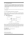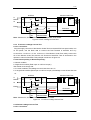
1
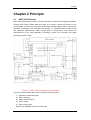
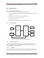
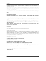
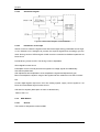
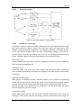
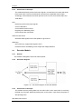
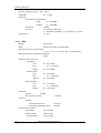
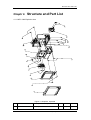
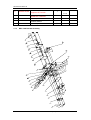
MEC-1000
Portable
Patient Monitor
Service Manual
Copyright
SHENZHEN MINDRAY BIO-MEDICAL ELECTRONICS CO., LTD. 2003
Version:
1.1
Issued date:
May 20, 2005
Series No.:
MEC-1000
Statement
SHENZHEN MINDRAY BIO-MEDICAL ELECTRONICS CO., LTD. (hereinafter called Mindray)
owns all rights to this unpublished work and intends to maintain this work as confidential.
Mindray may also seek to maintain this work as an unpublished copyright. This publication is
to be used solely for the purposes of reference, operation, maintenance, or repair of Mindray
equipment. No part of this can be disseminated for other purposes.
In the event of inadvertent or deliberate publication, Mindray intends to enforce its rights to
this work under copyright laws as a published work. Those having access to this work may
not copy, use, or disclose the information in this work unless expressly authorized by Mindray
to do so.
All information contained in this publication is believed to be correct. Mindray shall not be
liable for errors contained herein nor for incidental or consequential damages in connection
with the furnishing, performance, or use of this material. This publication may refer to
information and protected by copyrights or patents and does not convey any license under the
patent rights of Mindray, nor the rights of others. Mindray does not assume any liability arising
out of any infringements of patents or other rights of third parties.
Content of this manual is subject to changes without prior notice.
PROPERTY OF
SHENZHEN MINDRAY BIO-MEDICAL ELECTRONICS CO., LTD. 2003
ALL RIGHTS RESERVED
Responsibility on the manufacturer party
Mindray is responsible for safety, reliability and performance of this equipment only in the
condition that:
• all installation, expansion, change, modification and repair of this equipment are conducted
by Mindray qualified personnel; and,
• applied electrical appliance is in compliance with relevant National Standards; and,
MEC-1000 Service Manual (V1.1)
I
• the monitor is operated under strict observance of this manual.
Note
This equipment is not intended for family usage.
Warning
This monitor is not a device for treatment purpose.
It is important for the hospital or organization that employs this equipment to carry out a
reasonable maintenance schedule. Neglect of this may result in machine breakdown or injury
of human health.
Upon request, Mindray may provide, with compensation, necessary circuit diagrams,
calibration illustration list and other information to help qualified technician to maintain and
repair some parts, which Mindray may define as user serviceable.
II
MEC-1000 Service Manual (V1.1)
Warranty
Workmanship & Materials
Mindray guarantees new equipment other than accessories to be free from defects in
workmanship and materials for a period of one year (six months for multi-site probes and
SpO2 sensor) from date of shipment under normal use and service. Mindray's obligation
under this warranty is limited to repairing, at Mindray’s option, any part which upon Mindray's
examination proves defective.
THIS WARRANTY IS EXCLUSIVE AND IS IN LIEU OF ALL OTHER WARRANTIES,
EXPRESSED OR IMPLIED, INCLUDING WARRANTIES OF MERCHANT ABILITY OR
FITNESS FOR ANY PARTICULAR PURPOSE.
Exemptions
Mindray's obligation or liability under this warranty does not include any transportation or
other charges or liability for direct, indirect or consequential damages or delay resulting from
the improper use or application of the product or the substitution upon it of parts or
accessories not approved by Mindray or repaired by anyone other than a Mindray authorized
representative.
This warranty shall not extend to any instrument which has been subjected to misuse,
negligence or accident; any instrument from which Mindray's original serial number tag or
product identification markings have been altered or removed, or any product of any other
manufacturer.
Safety, Reliability and Performance
Mindray is not responsible for the effects on safety, reliability and performance of the
MEC-1000 Patient Monitor if:
■
assembly operations, extensions, re-adjusts, modifications or repairs are carried out by
persons other than those authorized by Mindray.
■
the MEC-1000 Patient Monitor is not used in accordance with the instructions for use, or
the electrical installation of the relevant room does not comply with NFPA 70: National
Electric Code or NFPA 99: Standard for Health Care Facilities (Outside the United States,
the relevant room must comply with all electrical installation regulations mandated by the
local and regional bodies of government).
MEC-1000 Service Manual (V1.1)
III
Return Policy
Return Procedure
In the event that it becomes necessary to return a unit to Mindray, the following procedure
should be followed:
1.
Obtain return authorization. Contact the Mindray Service Department and obtain a
Customer Service Authorization (Mindray) number. The Mindray number must appear on
the outside of the shipping container. Return shipments will not be accepted if the
Mindray number is not clearly visible. Please provide the model number, serial number,
and a brief description of the reason for return.
2.
Freight policy. The customer is responsible for freight charges when equipment is
shipped to Mindray for service (this includes customs charges).
Company Contact
Address:
Mindray Building, Keji 12th Road South, Hi-tech Industrial
Park, Nanshan, Shenzhen, 518057, P. R. China
Phone:
+86 755 2658 2888
Fax:
+86 755 2658 2680
EC Representative
IV
Name:
Shanghai International Holding Corp. GmbH(Europe)
Address:
Eiffestrasse 80 D-20537 Hamburg Germany
Phone:
+49 40 2513174
Fax:
+49 40 255726
MEC-1000 Service Manual (V1.1)
Preface
This service manual gives a detailed description of the MEC-1000 Patient Monitor, including
circuit descriptions, test procedures and a spare part listing. This manual is intended as a
guide for technically qualified personnel during repair, testing or calibration procedures.
Following symbols indicates some important facts that you have to pay special attention to:
Warning
Caution
Note
Points to be noted to avoid injury to the patient and the operator.
Points to be noted to avoid damage to the equipment.
Points to be noted.
MEC-1000 Service Manual (V1.1)
V
Contents
Contents
Chapter 1 General........................................................................................................... 1-1
Chapter 2 Principle......................................................................................................... 2-1
2.1 MEC-1000 Principle ................................................................................................. 2-1
2.2 Main control part ...................................................................................................... 2-3
2.3 Parameter Part......................................................................................................... 2-4
2.4 Power Board ............................................................................................................2-9
2.5 Key Board……………………………………………………………………………….2-11
2.6 Recorder………………………………………………………….……….……….2-12
Chapter 3 Product specification.................................................................................... 3-1
3.1 Classification............................................................................................................ 3-1
3.2 Specification............................................................................................................. 3-1
Chapter 4 I Structure and Part List ............................................................................... 4-1
4.1MEC-1000 Explosive view ........................................................................................ 4-1
4.1.1 MEC-1000 Explosive view .................................................................................... 4-1
4.1.2 MEC-1000 TFT Screen Assembly……………………………………. .................... 4-3
4.1.3 MEC-1000 Bracket Assembly ............................................................................... 4-5
4.1.4 Parameter Socket Assembly................................................................................. 4-7
4.1.5 Rear panel Assembly……………………………………. ....................................... 4-8
4.2 Use of Battery .......................................................................................................... 4-9
4.3 Part List .................................................................................................................. 4-9
Chapter 5 Tests............................................................................................................... 5-1
5.1 Test Procedure ........................................................................................................ 5-1
5.2 NIBP Calibrating Method ......................................................................................... 5-3
5.3 Safety tests……………………………………. ......................................................... 5-3
Chapter 6 Maintenance and Cleaning........................................................................... 6-1
Chapter 7 Troubleshooting............................................................................................ 7-1
Chapter 8 Maintenance menu........................................................................................ 8-1
MEC-1000 Service Manual (V1.1)
I
General
Chapter 1 General
MEC-1000 is a flexible, portable patient monitor. MEC-1000 can monitor physiological signals
including ECG, RESP. Rate, NIBP, SpO2, and TEMP. MEC-1000 can convert these
physiological signals into digital signals, which can be further processed and used to judge
whether to trigger alarm. The user can control the operation of MEC-1000 via using the
buttons on the front panel. MEC-1000 can be connected to the central monitoring system via
the Mindray network so as to form a network monitoring system.
MEC-1000 uses ECG electrodes, SpO2 finger sensor, blood pressure cuff and temperature
probe to measure the physiological signals including ECG, NIBP, SpO2, TEMP and RESP
Rate. In the process of measurement no energy or substances are extracted from and/or
delivered to the patient with the exception that sine wave signals are delivered to the patient
during measuring RESP Rate. MEC-1000 converts the acquired physiological signals into
digital signals, waveform and numerical values and displays all information on the screen. The
user can also control the operation of the monitor via using the buttons on the front panel. The
user can set alarm limits for each parameter. In this way once finding a physiological
parameter exceed the pre-set alarm limits, MEC-1000 will activate its visual and audio alarm
(the numerical display flashes or lights on) in order to raise the user’s attention.
1.1 General
During treatment, it is highly important to continuously monitor the vital physiological signs of
the patient to transmit the important information. Therefore patient monitor has always been
occupying a very important position in the filed of medical devices. The continuous
improvement of technologies not only helps us transmit the vital physiological signs to the
medical personnel but also simplifies the measurement and as a result raise the monitoring
efficiency. For inpatients, we need to measure those vital cardiac and pulmonary signs such
as ECG, SpO2, blood pressure and TEMP, etc. In recent years, the technological improvement
pertaining to measurement and information transmission has led to more comprehensive
performance and stable quality of the patient monitoring products. In the past, the dominant
products manufactured by medical device manufacturers are mainly those for single
parameter measurement. Nowadays however multi-parameter patient monitors are more
widely and commonly used.
1.2 Intended Use
MEC-1000 patient monitor can measure physiological signals including ECG, RESP., NIBP,
SpO2 and TEMP. It can convert these physiological signals into digital signals and further
display them on the screen. The alarm limits can be user-defined. Once finding a parameter
reach or exceed its pre-set alarm limits, MEC-1000 can automatically activate the
corresponding alarm. In addition, the user can operate the monitor by using the buttons on
the front panel. In addition to outpatient department, monitors are generally used in some
clinical areas such as ICU, CCU, operation room and emergency room because the monitor
can provide many other physiological parameters of the patient to medical personnel. Only
MEC-1000 Service Manual (V1.1)
1-1
General
the qualified medical personnel shall use MEC-1000 patient monitor.
1.3 Environmental Conditions
1.3.1
Temperature
Operating
0 - 40 °C
Transportation and Storage
-20 - 60 °C
1.3.2
Humidity
Working
Transport and Storage
1.3.3
15% ~ 95%
10% ~ 95%(noncondensing)
Altitude
Operating
-500 to 4,600 meters
Transportation and Storage
-500 to 13,100 meters
1.3.4
Electrical specification
100-250 VAC, 50/60Hz,max. input power consumption 110VA
1-2
MEC-1000 Service Manual (V1.1)
Principle
Chapter 2 Principle
2.1
MEC-1000 Principle
MEC-1000 portable patient monitor has been designed to measure physiological parameters
including ECG, RESP, TEMP, NIBP and SPO2, etc. Figure2-1 shows the structure of the
whole monitor as well as the connection relationships between different parts. The board in
the center of the figure is the core part of the monitor, i.e., integrated board for main control
and parameter measurement, which, though being a single board, could realize the
measurements of five said parameters; accordingly uniform AD conversion and digital
processing system is used.
Figure 2- 1 MEC-1000 structure and part relationship
In terms of its functionality, MEC-1000 is made up of following parts:
1) Parameter measurement part
2) Main control part
3) Man-machine interface
4) Power supply
5) Other auxiliary part
Below is the detailed introduction to each part.
MEC-1000 Service Manual (V1.1)
2-1
Principle
2.1.1
Parameter measurement part
Parameter measurement and monitoring are primary functions of the monitor. The parameter
measurement part of the monitor consists of measurement probe (excluded in figure 2-1),
parameter input socket assembly, NIBP assembly and the parameter part of the main control
board. Its function is to convert the physiological signals into electronic signals, process them
and execute calculations according to pre-set programs or the commands from the main
control part, and then to send data of values, waveforms and alarms back to the main control
part. The data will then be displayed via man-machine interface.
2.1.2
Main control part
The main control part of the integrated board is to drive man-machine interface, manage
parameter measurement and provide other specific functions to the user such as
configuration storage, waveform and data recall, etc.
2.1.3
Man-machine interface
The man-machine interfaces are LCD display, recorder, speaker, indicator, keys and knob.
The LCD display is the most primary output interface, displaying real-time or history data and
waveforms, various patient information and alarm prompts on the screen for the user’s
observation.
Recorder is an auxiliary device to the display, which could print out various user-selected data
for use and preservation.
Speaker gives audio alarm.
Indicator provides additional information about power supply, battery and alarm.
Keys and knob are user input interface of the system, by using which the user could input
information and instructions into the monitor.
2.1.4
Power supply
Power supply is an important part of the system, consisting of power board, backlight board,
battery and fan.
The main power board converts the AC mains input into 5V and 12V DC to energize other
parts of the system. Similarly LCD display requires particular supply, for which case a
backlight board is supplied. The battery could maintain the formal function of the system for a
short period when AC mains is disconnected. A small fan requiring DC input is used to realize
superior ventilation.
2.1.5
Other auxiliary part
Network port is available on MEC-1000, which allows the service engineer to upgrade the
system software without necessarily opening the enclosure of the monitor.And can be
2-2
MEC-1000 Service Manual (V1.1)
Principle
connected to the Minday Center manage System.
2.2
Main Control Part
2.2.1
Functions of main control part
As the core part of the whole system, it finishes the following functions:
1) control, management and scheduling of parameter measurement part, recorder and
keyboard;
2) display drive of TFT screen, STN screen and CRT screen;
3) 3-way expansion serial port realized by FPGA;
4) alarm given for system fault;
5) storage of RTC, hardware WatchDog and relevant parameters
2.2.2
Schematic Diagram
UART
interface
RTC
CPU System
RAM/ROM
FPGA
Watchdog
Display
interface
VRAM
Figure 2-2 Schematic Diagram of Main Control Part
2.2.3
Introduction to Principle
The main control Module, being the center part of the system, has serial ports to various
modules, TFT display interface, CRT display interface. The BDM interface is reserved on the
board for debugging or downloading software.
2.2.3.1
CPU System
CPU is the core element on the main control Module. It connects peripheral modules through
BUS and I/Os in order to finish data communication, data processing and logic control, etc.
MEC-1000 Service Manual (V1.1)
2-3
Principle
2.2.3.2
RTC
RTC (real-time clock) provides time (hour, minute, second) and date (year, month, day)
information. RTC information can be changed by CPU.
2.2.3.3
FPGA and VRAM
VRAM is used to save display data. CPU sends display data to VRAM via FPGA. The data in
VRAM is a map of the real display device.
FPGA has various extended serial ports, which communicate with external Parameter Parts.
CPU writes acquired data to FPGA, and FPGA sends it to external Parameter Parts.
2.2.3.4
Watchdog
Upon power-up, Watchdog supplies Reset signals to CPU, FPGA and Ethernet Controller.
Provide functions of Waterdog Timer Output and voltage supervise.
2.2.3.5
Ethernet Controller
Ethernet Controller complies with IEEE802.3 / IEEE802.3u LAN standard, supports 10Mbps
and 100Mbps data rates, and realizes the data communication between CPU and Ethernet.
2.3
Parameter Part
2.3.1
Introduction to Principle
The parameter part collects, amplifies and filters the signals of the said five physiological
parameters, executes A/D over the signals and processes the result signals. Figure 2-3 shows
the structure of this part.
ECG\RESP
Signal
Input\Process
TEMP Signal
Input\Process
CPU
System
A/D
Power &
Signal
isolate
SPO2 Signal
Input\Process
Circuit
NIBP Signal
Input\Process
Watchdog
Figure 2-3 Schematic Diagram of Parameter Part
A/D and CPU in parameter part are shared for processing signals of the said five parameters,
i.e., ECG, RESP, TEMP, NIBP and SPO2.
A/D
Convert analog signals output from parameter circuit into digital signals, and send them
2-4
MEC-1000 Service Manual (V1.1)
Principle
into CPU part to receive further processing.
CPU System
Realize logic control over all parameter parts and A/D part.
Process data of each parameter;
Communicate with main board.
Power & Signal isolate Circuit
Realize isolation from external circuit in order to ensure human safety;
Provide power supplies for circuits;
Realize isolating communication between CPU System and main board.
Watchdog
Upon power-on, supply Reset signal to CPU;
Provide functions of Watchdog Timer Output and voltage detection.
2.3.2
2.3.2.1
ECG/RESP Module
General
This module is designed to measure two parameters including ECG, RESP.
2.3.2.2
Schematic Diagram
Figure 2-4 Schematic Diagram of ECG/RESP Module
2.3.2.3
Introduction to Principle
This module uses ECG cables to collect ECG, RESP signals, process them and transmit them
to the main control part through serial port.
ECG Signal Input Circuit
Input protection and filter circuit: receives ECG signals from cables, removes high-frequency
MEC-1000 Service Manual (V1.1)
2-5
Principle
interference and prevents the circuit from being damaged by high voltage generated in
defibrillation and ESD.
Right leg drive circuit: picks up 50/60Hz common-mode signals in lead wire and feeds them
back to patient body; suppresses the common-mode interference in lead wire for the sake of
better detecting ECG signals.
Lead Off detection circuit: detects if any ECG lead falls off and transmits relevant message to
CPU.
ECG Signal Process Circuit
Differential Amplification circuit: first-order amplifies ECG signals and suppresses
common-mode interference at the same time.
Low-pass filter circuit: removes high-frequency interference outside frequency band of ECG
signals.
PACE signals are ECG pacing signals, which greatly affect ECG detecting performance.
Therefore PACE suppression circuit is designed to suppress PACE signals in order to better
detect ECG signals.
Master AMP/Filter circuit: amplifies and filters ECG signals again and transmits them
furthermore into A/D converter.
Pace Detect
Pick PACE signals out of ECG signals and transmit them to CPU.
Carrier Generate Circuit
RESP measurement is based on Impedance method. Respiration causes the changes of
thoracic impedances, which feature is taken advantage to modulate the amplitude of high
frequency carrier. The modulated signals are then sent into the measuring circuit. This circuit
is designed to generate high frequency carrier
RESP Signal Input Circuit
Couples the RESP signals into the detection circuit.
RESP Signal Process Circuit
Preamplifier circuit: amplifies and filters RESP signals;
Detection circuit: picks out the RESP wave modulated in excitation signals;
Level translation circuit: removes DC components in RESP signals;
Master AMP/Filter circuit: amplifies and filters RESP signals again and transmits them
furthermore into A/D converter.
A/D and CPU System (Description in frame of dashed lines)
Refer to the 2.3.1
2-6
MEC-1000 Service Manual (V1.1)
Principle
2.3.3
TEMP Module
2.3.3.1
General
This module uses sensors to collect TEMP signals, process them and transmit them to the
main control part through serial port.
2.3.3.2
Schematic Diagram
Figure 2-5 Schematic Diagram of TEMP Module
2.3.3.3
Introduction to Principle
Measure temperature of body surface or endocavity by taking advantage of the characteristics
of the thermal-sensitive resistor whose impedance varies with temperature of human body.
Temperature Detect Circuit
Receive the signal transmitted from TEMP sensor, amplify the signal and send it into A/D
converter.
A/D and CPU System (Description in frame of dashed lines)
Refer to the 2.3.1
2.3.4
2.3.4.1
SPO2 Module
General
This module is designed to measure SPO2.
MEC-1000 Service Manual (V1.1)
2-7
Principle
2.3.4.2
Schematic Diagram
Figure 2-6 Schematic Diagram of SPO2 Module
2.3.4.3
Introduction to Principle
Sensor is used to collect the signals of red and infrared lights having penetrated human finger
or toe. Relevant unit is designed to process the acquired signals and accordingly give the
result. Driving current of LED and gain of AMP circuit are controlled to fit different patients.Led
Drive Circuit
Provide driving current to LED. The driving current is adjustable.
SPO2 Signal Process Circuit
Preamplifier circuit converts photocurrent signals into voltage signals and additionally
first-order amplifies them;
Gain adjustment and amplification circuit amplifies the signals and adjusts their gain;
Bias circuit adjusts the dynamic range of the signals and then sends them into A/D converter.
D/A
Convert digital signals output from CPU into analog signals, supply control signals to Led
Drive Circuit and SPO2 Signal Process Circuit.
A/D and CPU System (Description in frame of dashed lines)
Refer to the 2.3.1
2.3.5
2.3.5.1
NIBP Module
General
This module is designed to measure NIBP.
2-8
MEC-1000 Service Manual (V1.1)
Principle
2.3.5.2
Schematic Diagram
Figure 2-7 Schematic Diagram of NIBP Module
2.3.5.3
Introduction to Principle
Oscillometric method is adopted to measure NIBP. Inflate the cuff wrapped around the upper
arm until the pressure makes the blood in the artery of the upper arm stops flowing. Then
deflate the cuff according to the requirement of the algorithm. Blood flow in the artery resumes
as the cuff pressure decrease, which will cause corresponding pulsation in the cuff. The
pressure sensor connecting the inflating hose of the cuff will accordingly generate pulsating
signals. The NIBP module can process these signals and give measuring result.
Valve Drive Circuit
Control OPEN/CLOSE of the valve. This circuit, together with Motor Drive Circuit, finishes the
action of inflating and deflating cuff.
Motor Drive Circuit
Control the action of air pump. This circuit, together with Valve Drive Circuit, finishes the
action of inflating and deflating cuff. Moreover, it supplies motor status signal to A/D converter
for detection.
NIBP Signal Process Circuit
NIBP signals are differential signals. Differential Amplify circuit amplifies the differential
signals and converts them into single ended signals and at the same time sends the signal of
one way to A/D converter and the signal of the other way to the Blocking and AMP circuit.
Blocking and AMP circuit removes the DC components in the signals, amplifies the signals
and then sends them into A/D converter.
Over Pressure Detect
Detect NIBP pressure signals. Once the pressure exceeds the protection limit, it sends the
message to CPU System, which will accordingly control the Valve Drive Circuit to open the
MEC-1000 Service Manual (V1.1)
2-9
Principle
valve to deflate the cuff so as to reduce the pressure.
A/D and CPU System (Description in frame of dashed lines)
Refer to the 2.3.1
2.4
Power Board
2.4.1
General
This module provides DC supplies to other boards.
2.4.2
Schematic Diagram
Figure 2-8 Schematic Diagram of Power Board
2.4.3
Introduction to Principle
This module converts 220V AC mains or battery power into 5V and 12V DC supplies to
power other boards. If AC mains and battery coexist, the former take the priority to power
the system and charge the latter at the same time.
AC/DC
Convert high-voltage AC supply into low-voltage DC supplies to power subsequent
circuits and charge the battery.
Battery Control Circuit
If AC mains and battery coexist, this circuit controls the output from AC/DC part to charge
the battery. If AC mains is disconnected, this circuit controls the battery to power the
subsequent circuits.
5V DC/DC
Convert the DC supply from the previous circuit into stable 5V DC supply to power other
boards.
12V DC/DC
2-10
MEC-1000 Service Manual (V1.1)
Principle
Convert the DC supply from the previous circuit into stable 12V DC supply to power other
boards.
Power Switch Circuit
Control the working status of 5V DC/DC and 12V DC/DC in order to control ON/OFF
action of the patient monitor.
Voltage Detect Circuit
Detect the output voltages of various parts of the circuits; convert the analog signals into
digital signals and send them into main board for further processing.
2.4.4
Testing key points
After connecting AC mains, the DC voltage over C12 is about 1.3 ~ 1.4 time of AC input
voltage; voltage over C15 is 17.6V. Voltage over C24 is 13.8V when battery is disconnected.
Voltage over C47 is 5V applied to power U7, U8 and U9. Voltages of pin8 of U1, pin8 of U10
and pin11 of U11 to the ground are all 5V. Voltage of pin2 of U10 to the ground is 2.5V. On the
oscillograph, we can observe that voltage waves of pin4 of U11 and pin4 of U10 to the ground
are standard toothed waves of 120kHz oscillating frequency. Voltage waves of pin1 of Q1 and
pin1 of Q5 when output is connected with rated load are square waves of about 120kHz
frequency. Voltage wave of D16 is a square one of about 280kHz frequency.
2.5
Keyboard
2.5.1
General
This module acts as the man-machine interface.
2.5.2
Schematic Diagram
Figure 2-9 Schematic Diagram of Keyboard
MEC-1000 Service Manual (V1.1)
2-11
Principle
2.5.3
Introduction to Principle
This module detects key and encoder input signals, converts them into codes and sends
to the main board. The main board sends command to the keyboard and the latter
accordingly control indicator and audio process circuit to act so as to realize audio and
visual alarm.
CPU
Detect key and encoder input signals;
Control LED status;
Control Audio Process Circuit;
Regularly zero Watchdog Timer;
Communicate with main board.
Audio Process Circuit
Generate audio signals to drive the speaker to give sound.
Watchdog
Upon power-up, supply Reset signal to CPU;
Provide functions of Waterdog Timer Output and voltage detection.
2.6
Recorder Module
2.6.1
General
This module is designed to drive line thermal printer.
2.6.2
Schematic Diagram
Figure 2-10 Schematic Diagram of Recorder Module
2.6.3
Introduction to Principle
This module receives printing data from the main board. At the same time of converting
the data into dot matrix data and sending them to the printer, it also drives the printer to
start printing action.
Step Motor Drive Circuit
2-12
MEC-1000 Service Manual (V1.1)
Principle
A step motor is used in the printer to feed paper. This circuit is designed to drive the step
motor to act.
Printer Status Detect Circuit
Detect the status of the printer, including the position of paper platen, if there is paper,
and temperature of thermal head and send the information to CPU System.
CPU System
Process printing data;
Control printer and step motor;
Collect printer status information and realize corresponding control;
Communicate with main board.
MEC-1000 Service Manual (V1.1)
2-13
Product Specification
Chapter 3 Product Specification
3.1
Classification
Anti-electroshock type
EMC type
Anti-electroshock degree
Harmful liquid proof degree
Working system
3.2
Class I equipment with internal power supply
Class A
ECG (RESP), SpO2, NIBP, TEMP
CF
Ordinary equipment (sealed equipment without liquid proof)
Continuous running equipment
Specifications
3.2.1 Size and Weight
Size
Weight
3.2.2
318 x 152 x 264 mm
4 kg
Environment
Temperature
Working
Transport and Storage
0 ~ 40 °C
-20 ~ 60 °C
Working
Transport and Storage
15% ~ 95%
10% ~ 95%(noncondensing)
Humidity
Altitude
Working
Transport and Storage
Power Supply
3.2.3
-500 ~ 4,600m
-500 ~ 13,100m
100 ~ 250 VAC, 50/60 Hz,
Pmax=110 VA
FUSE T 1.6A
Battery
Rechargeable Lead-Acid
2.3Ah 12V
Operating time under the normal condition
100 minutes (2 batteries)
Operating time after the first alarm of low battery
5 ~ 15 minutes
Maximum charging time of single battery is 4 hours. Maximum charging time of two
batteries is 8 hours.
MEC-1000 Service Manual (V1.1)
3-1
Product Specification
3.2.4
Display
Screen
Messages
10.4” Color TFT, 800 x 600 Resolution
4 Waveforms Maximum
1 Alarm LED (Yellow/Red)
1 Power LED (Green)
1 Charge LED (Green)
3 Sound Modes corresponding to Alarm Modes
3.2.5
Signal Interface
Do not have this function
3.2.6
Recorder
Record Width
Paper Speed
Trace
Recording types:
48 mm
25/50 mm/S
2
Continuous real-time recording
8 second real-time recording
Auto 8 second recording
Parameter alarm recording
Waveform freeze recording
Trend graph/table recording
ARR events review recording
Alarm event review recording
NIBP review recording
Drug Calculation and titration table recording
Monitor information recording
3.2.7
Recall
Trend Recall
Short
Long
1 hour, 1 or 5 second Resolution
72 hours, 1 minute Resolution
Alarm Event Recall
60 alarm events of all parameters and 8/16/32seconds of corresponding waveform.
NIBP Measurement Recall
400 NIBP measurement data
Power-off Storage
3-2
MEC-1000 Service Manual (V1.1)
Product Specification
72 hours of trend data, 400 NIBP measurement data, 60 alarm events and 60 Arr.
Events
3.2.8
ECG
Lead Mode
Lead selection
Waveform
3 Leads (R, L, F or RA, LA, LL)
I, II, III
1 channel
Gain
HR and Alarm
×0.25mm/mV, ×0.5mm/mV, ×1mm/mV, ×2mm/mV, AUTO
Range
Adult
Neo/Ped
Accuracy
Resolution
Sensitivity
Differential Input Impedance
CMRR
15 ~ 300 bpm
15 ~ 350 bpm
±1% or ±1bpm, use the greater
1 bpm
> 200uV (Vp-p)
> 5 MΩ
Monitor
Surgery
Diagnostic
> 105 dB
> 105 dB
> 90 dB
Electrode offset potential
Leakage Current
Defibrillation Recovery Time
±300mV
< 10 uA
< 3s After Defibrillation (in Monitor or Surgery mode)
ECG Signal Range
Frequency Response (Bandwidth)
Surgery
Monitor
Diagnostic
± 5mV (Vp-p )
1 ~ 15 Hz
0.5 ~ 35 Hz
0.05 ~ 100 Hz
Calibration Signal
1mV (Vp-p), Accuracy: ±5%
ST Segment Monitoring Range
Measure and Alarm -2.0 ~ +2.0 mV
ARR Detecting
Type
ASYSTOLE, VFIB/VTAC, COUPLET, BIGEMINY,
TRIGEMINY, R ON T, VT>2, PVC, TACHY, BRADY,
MISSED BEATS, PNP, PNC
Alarm
Available
Review
Available
3.2.9
RESPARATION (RESP)
Method
Impedance between R-F (RA-LL)
Measuring Impedance Range:0.3 ~ 5.0Ω
MEC-1000 Service Manual (V1.1)
3-3
Product Specification
Base line Impedance Range: 200 ~ 1500Ω
Bandwidth
0.3 ~ 2.5 Hz
Resp. Rate
Measuring and Alarm Range
Adult
0 ~ 120 BrPM
Neo/Ped
0 ~ 150 BrPM
Resolution
1 BrPM
Accuracy
0 ~ 6 BrPM: Unspecified
7 ~ 150 BrPM: ±2 BrPM or ±2% whichever is greater
Apean Alarm
10 ~ 40 s
3.2.10
NIBP
Method
Oscillometric
Mode
MANUAL, AUTO, CONTINUOUS
Measuring Interval in AUTO Mode
1, 2, 3, 4, 5, 10, 15, 30, 60, 90, 120, 180, 240,480Min
Measuring Period in CONTINUOUS Mode
5 Min
Measuring and alarm range
Adult Mode
SYS
40 ~ 270 mmHg
DIA
10 ~ 215 mmHg
MEAN
20 ~ 235 mmHg
Pediatric Mode
SYS
40 ~ 200 mmHg
DIA
10 ~ 150 mmHg
MEAN
20 ~ 165 mmHg
Neonatal Mode
SYS
40 ~ 135 mmHg
DIA
10 ~ 100 mmHg
MEAN
20 ~ 110 mmHg
Resolution
Pressure
1mmHg
Static pressure accuracy
± 3mmHg
Accuracy
Pressure
Maximum Mean error
±5mmHg
Maximum Standard deviation
8mmHg
Overpressure Protection
Adult Mode
297±3 mmHg
Pediatric Mode
240±3 mmHg
Neonatal Mode
147±3 mmHg
3-4
MEC-1000 Service Manual (V1.1)
Product Specification
3.2.11
SpO2
Measuring Range
Alarm Range
Resolution
Accuracy
0 ~ 100 %
0 ~ 100 %
1%
Actualization interval
Alarm Delay
Pulse Rate
Measuring and Alarm Range
70% ~ 100%: ±2 %
0% ~ 69%:
about 1s
10s
Resolution
20 ~ 254bpm
1bpm
Accuracy
Alarm Delay
± 3bpm
10s
Unspecified
3.2.12 TEMPERATURE (TEMP)
Channel
1
Measuring and Alarm Range
Resolution
Accuracy
Actualization interval
0 ~ 50 °C
0.1°C
± 0.1 °C
about 1 Sec.
MEC-1000 Service Manual (V1.1)
3-5
Structure and Part List
Chaptr 4
Structure and Part List
4.1.1 MEC-1000 Explosive view
Figure 4-1 Graphics, exploded
1
M1K1-30-22368
Front panel assembly
1
2
M04-004012---
Cross phoned screw with washer
4
MEC-1000 Service Manual (V1.1)
4-1
Structure and Part List
M3x6
3
9300-30-13793
or M1K1-30-22355
10.4’ Au TFT screen Assembly
1
or 10.4’TFT LG 800*600 screen
Assembly
4
M04-003105---
Screw GB845-85 M3x8
2
5
9303-30-21801
6 Pin parameter socket panel
1
6
M04-000305---
Screw GB845-85 M3x12
4
7
9000-20-05185
Battery Door
1
8
M04-000802---
Washer GB972-3
2
9
9303-30-21804
Bracket Assembly
1
10
M1K1-30-22305
Rear panel assembly
1
11
TR6C-30-16657
TR6C-C recorder package
1
12
M04-004014---
Cross phoned screw with washer
4
M4x10
13
M04-004017---
Cross phoned screw with washer
2
M3x12
SN
4.1.2
4-2
Standard Code
Name & SPEC.
MEC-1000 TFT Screen Assembly
MEC-1000 Service Manual (V1.1)
QTY.
Material
Remarks
Structure and Part List
Figure 4-2-1 MEC-1000 LG TFT screen assembly
M04-051137---
Cross phoned screw GB 818-85
1
with washer M2x4
4
2
9300-20-13911
TFT support bar(LP104S5”LG”)
2
3
0010-10-12362
10.4’ LG TFT screen
1
4
9300-20-13911
TFT support bar(LP104S5”LG”)
1
5
M04-004012---
Hexagon Nut M3x6
4
6
9300-20-13901
Isolation panel
1
7
0010-10-12096
INVERTOR”TAMURA”
1
8
M04-002405---
Isolation Washer
2
SN
Standard Code
Name & Specification
QTY.
LY12
T=1.5
Material
Remarks
Figure 4-2-2 MEC-1000 Au TFT screen assembly
M04-000805--1
Cross
phoned
screw
with
washer M2x8
10
2
M04-000102---
Hexagon Nut M3x6
4
3
0010-10-12357
10.4’ AU TFT screen
1
4
9300-20-13972
Pole M2 x14
4
MEC-1000 Service Manual (V1.1)
4-3
Structure and Part List
5
9300-20-13766
Support of TFT screen
1
6
0010-10-12096
INVERTOR ”TAMURA”
1
7
9300-20-13901
Isolation panel
1
8
M90-000002-01
Isolation Washer
2
SN
Standard Code
Name & Specification
4.1.3
4-4
QTY.
MEC-1000 Bracket Assembly
MEC-1000 Service Manual (V1.1)
LY12
T=1.5
Material
Remarks
Structure and Part List
Figure 4-3 MEC-1000 bracket assembly
1
M04-004012---
Cross
phoned
screw
with
21
washer M3x6
2
8100-30-14117
NIBP Pump assembly
1
3
9200-30-10489
Power board
1
4
9200-20-10515
Isolation panel of Power board
1
5
9303-30-21803
Socket panel Assembly
1
6
9200-20-10689
Recorder Adjust Board
1
7
9200-20-10485
Printer Install Board
1
8
9000-30-05178
Battery backboard
1
9
M04-005005---
Screw GB819-85 M3x6
12
10
9200-20-10545
Isolation panel for main board
1
11
M04-000301---
NUT GB617II-M3
2
12
5000-20-14634
Bottom shield of Main board
1
13
5000-20-14632
Isolation panel for the shield
1
14
5100-30-26870
Main Board(ALL in one Board)
1
15
5000-20-14633
Top shield of Main Board
1
16
M04-002505---
Screw GB818-86 M3x6
2
17
9200-30-10492
Battery Box Assembly
1
18
M1K1-21-22358
Bracket
1
SN
Standard Code
Name & SPEC.
QTY.
MEC-1000 Service Manual (V1.1)
Material
Remarks
4-5
Structure and Part List
4.1.4
Parameter Socket Assembly
Figure 4-4 Parameter socket assembly
4-6
MEC-1000 Service Manual (V1.1)
Structure and Part List
1
M04-002405---
Screw GB818-86 M2x6
4
2
M04-000102---
Washer GB97.2 2
4
3
M04-004012---
Cross phoned screw with washer
M3x6
6
4
9303-20-21814
Single TEMP signal Cable
1
5
9000-20-05204
Washer of TEMP probe
1
6
9200-20-10510
Front Board of the probe Socket
1
7
9303-20-21800
Panel of the parameter Socket
1
8
9303-20-21813
SPO2 SIGNAL CABLE
1
9
509B-10-06191
Connector 20SFTS 04MxN
1
10
9200-20-05205
Fixing board for the NIBP Module
1
11
M04-011002---
M3 Nut
2
12
9200-20-10491
Back board of the probe socket
1
13
9303-21-21812
ECG signal Cable
1
SN
Standard Code
Name & SPEC.
QTY.
4.1.5
Material
Remarks
Rear Panel Assembly
Figure 4-5 Rear panel assembly
MEC-1000 Service Manual (V1.1)
4-7
Structure and Part List
1
M04-000305---
Screw M3x12
2
2
M04-000802---
Washer GB97.2 3
2
3
LMB9-20-09836
Cover board
1
4
9300-20-13822
Handle B
1
5
900E-20-04855
Rear panel
1
6
9200-20-10622
Install board
1
7
M04-003105---
Screw GB845-85 M3x6
8
8
9200-30-10522
FAN assembly
1
9
9200-20-10620
Press panel of Speaker
1
10
9200-21-10633
2.25” Speaker with Cable
1
11
9200-20-10511
Rubber foot 1
1
SN
Standard Code
Name & SPEC.
QTY.
4.2
Use of Battery
4.2.1
Assembly/disassembly
Figure 4-6 Assembly/disassembly of battery
4-8
MEC-1000 Service Manual (V1.1)
Material
Remarks
Structure and Part List
4.2.2
Precautions
(1) Battery specification: Lead-Acid 12V rechargeable battery
(2) Charging time: 6 hours
(3) Discharging time: if the monitor works to measure ECG/RESP/TEMP, SPO2,and NIBP
parameters and NIBP is in the mode of one measurement per five minutes, a battery
with full capacity can power the monitor continuously for 50 minutes. Five minutes
before the battery runs out of its capacity, the monitor will give audio and visual prompt.
(4) To extend the lifespan o the battery, it is recommended to use it at least once monthly.
Besides, the battery shall be charged after its capacity is completely exhausted.
4.3
Part list
Part List of MEC-1000
Name
Material No.
0010-20-11954
SPO2 plug
0010-20-11950
ECG plug
1000-21-00122
Grounding wire of machine enclosure
8000-20-10221
Plug of grounding cable
509B-10-05996
3-core power cord (plug LK-C02)
509B-30-06259
External NIBP hose (CE)
509B-30-08845
Finished adult cuff (OEM CE)
630C-20-08481
Adult NIBP cuff CM1203-1
512A-30-90106
Finger SpO2 sensor (OEM)
8000-21-10141
Power cord of DC/DC converter
8000-21-10276
Connecting wire of TR60C recorder of main control board
TR6C-30-16654
TR60-C recorder
5000-20-14633
Upper shielding cover of main board
5000-20-14634
Lower shielding cover of main board
5000-30-14630
Integrated parameter main control board
9200-30-14083
Main bracket
9000-20-05185
Battery Door
9200-30-10489
Power board
8100-30-14117
NIBP pump assembly
8100-30-14119
Backlight board assembly
9303-30-21803
Parameter socket assembly
MEC-1000 Service Manual (V1.1)
4-9
Structure and Part List
M05-100R29--9300-30-13793
or M1K1-30-22355
4-10
CR2032 button battery 3V lithium
Au TFT screen assembly
or LG TFT screen assembly
0010-10-12096
INVERTOR
M1K1-30-22368
Front panel assembly
9200-21-10633
Speaker
900E-20-04855
Rear panel
9000-10-07294
Accumulator
9210-30-30152
Network board
MEC-1000 Service Manual (V1.1)
Tests
Chapter 5 Tests
5.1
Test Procedure
5.1.1
Connection and Inspection
Connect the simulator, power supply and fixture onto MEC-1000 monitor; turn on the
power. TFT shall display startup picture and then the system screen.
5.1.2
Inspecting Key Functions
Press every key on the keypad. The system shall execute the corresponding function
as instructed in the operation manual. The encoder shall execute the corresponding as
well.
5.1.3
ECG/RESP test
TFT shall display standard ECG wave. The error between the heart rate and the setup
value of simulator shall not exceed ±1; that is 60±1. RESP wave shall be smooth and
uniform. RESP Rate shall be 20±1.
① Sequentially select all leads include Cal, four gain options and AUTO, FILTER and
NON-FILTER modes; the monitor shall give correct display. The 50/60HZ
interference shall be removed;
② Consistency shall exist for heart beat sound, flashing of heart symbol and
appearance of R wave in the above mentioned situations;
③ Gain has correct influence on HR calculation and judgment of “Weak ECG Signal”;
④ Verification of measuring range and accuracy: ECG signal amplitude of simulator is
1mV. Heart rate is respectively 60, 120, 200. Respectively connect lead I, II, and III,
the results shall satisfy 59~61, 119~121, 198~202;
⑤ PACE pulse test: set the simulator to PACE mode, change PACE amplitude to ±8~
700mv and pulse width to 0.1ms~2ms, the system shall distinguish PACE signal
and display LEAD OFF prompt correctly;
⑥ RESP measurement: set the baseline impedance to 1K and RESP resistance
respectively to 0.5Ω and 3Ω, RESP Rate respectively to 30 and 120, the system
shall measure the RESP Rate to be 29~31 and 118~122;
⑦ PVE test: set the simulator to PVC mode and set the appearing times as well, the
system shall detect the corresponding PVCS;
⑧ On the simulator, set RESP Rate to 40, base impedance to 2KΩ, and RESP wave to
3:1; set APNEA alarm to ON and adjust RESP resistance to 0Ω, the system shall
give different alarms corresponding to different APNEA time;
MEC-1000 Service Manual (V1.1)
5-1
Tests
5.1.4
TEMP Test
① YSI probe
Select YSI TEMP probe in the factory menu; select YSI TEMP probe in the fixture of
TEMP test; simulate resistance of 1.355K. The display for TEMP shall be 37±0.1℃ ;
② CY-F1 probe
Select CY-F1 TEMP probe in the factory menu, select CF-Y1 TEMP probe in the
fixture of TEMP test; simulate resistance of 6.018K. The display for TEMP shall be
37±0.1℃.
5.1.5
NIBP Test
Connect NIBP simulator, adult cuff and accessories; connect CUFF connector on the
module and turn it clockwise to tighten it.
1. After the simulator passes self-test, press “ENT” to enter ADULT NIBP mode. Set the
blood pressure to the grade of 255/195/215 mmHg, press SHIFT+15; set heart rate to
80BPM. Also set MEC-1000 to ADULT mode. Press “START” key, the system will give
calculating result about 30 seconds later. The results shall be respectively 270±8mmHg,
210±8mmHg and 230±8mmHg;
2. Press “ESC” and “↓” keys on the simulator to enter NEONATE mode. Set the blood
pressure to the grade of 120/80/90 mmHg and heart rate to 120BPM. Also set MEC-1000
to PEDIATRIC mode. Press “START” key, the system will give calculating result about 30
seconds later. The results shall be respectively
120±8mmHg, 80±8mmHg and
90±8mmHg;
3. Press “ESC” and “↓” keys on the simulator to enter NEONATE mode. Set the blood
pressure to the grade of 60/30/40, select SHIFT to be -20, set heart rate to 120BPM. Use
neonate cuff to replace simulator accessory. Press “START” key, the system will give
calculating result about 30 seconds later. The results shall be respectively 40±8mmHg,
10±8mmHg and 20±8mmHg.
5.1.6
SpO2 Test
Set HR FROM of MEC-1000 to PLETH. Put finger into SpO2 sensor. The system shall
display pulse rate and SpO2 value correctly. The SpO2 measured result of normal human
body shall be above 97%.
5.1.7
Recorder Printing Test
1. Print ECG wave, the recorder shall print normally. The output shall be clear, consistent.
Create faults like NO PAPER, the system shall give corresponding alarm prompt. The
recorder shall work normally after the fault is removed;
2. Execute alarm printing of every parameter. Set Alarm Record switch of every parameter to
ON, set up different alarm limits. The system shall execute parameter alarm printing
operation once there is parameter alarm.
5-2
MEC-1000 Service Manual (V1.1)
Tests
5.1.8
Power Supply Management
Connect external AC source, the CHARGE indicator on the front panel shall light on.
Disconnect the AC source, the CHARGE indicator shall light off. After the monitor is turned
on but device for testing battery is not installed, “x” symbol shall appear on the box indicating
the battery capacity. Whether the battery is installed or not does not affect the normal
function of the monitor. The system will give corresponding alarm once the battery capacity
is about to be used up.
5.1.9
Clock Check
When inspecting the whole monitor, check if the clock goes correctly. Then set the clock to
the current time.
5.1.10 Set Up the DEFAULT Value When Start Loading Software
Execute the operations indicated in the SYSTEM MENU, such as patient information
management, history recall and system setup. The system shall respond correctly and
normally. The running of the function shall have no obvious error. Each function complies with
corresponding requirement.
5.2
NIBP Calibrating Method
Figure 5-1 Method to calibrate NIBP static pressure
Method: increase pressure gradually in the increment of 50mmHg(6.kPa). The maximum error
between any pressure point in the NIBP measurement range of monitor and the value of
pressure calibrator shall not exceed ±3mmHg(±0.4kPa). Then decrease pressure gradually.
The maximum error between any pressure point in the NIBP measurement range of monitor
and the value of pressure calibrator shall not exceed ±3mmHg(±0.4kPa).
5.3
Safety tests
Testing device: BIO-TEK®601PRO safety analyzer
Applied standard: IEC60601-1
Inspection items and methods
5.3.1 Protective Earth Resistance Test
MEC-1000 Service Manual (V1.1)
5-3
Tests
5.3.1.1 Connection
Plug the supply connector of the Monitor Under Test into the 601PRO front panel outlet;
Performing the test as instructed in the Operator’s Manual of 601PRO. (Set testing current to
25A).
Test of item a: use the Red Testing Lead (accessory of 601PRO) to connect the Red Terminal
of 601PRO and Protective Earth Terminal or an access ib le m eta l par t of the Monitor
Under Test;
Test of item b: use the Red Testing Lead to connect the Red Terminal and the Protective Earth
Terminal of the Monitor Under Test; use the Black Testing Lead (accessory of 601PRO) to
connect the Green Terminal and any accessible co nduc tor. Test principle is as shown in
figure 5-2.
Testing results must comply with:
a The resistance between the Earth Terminal of the power supply cord of the Monitor Under
Test and the Protective Earth or any accessible conductor of the enclosure must be less than
0.2Ω;
b. The resistance between the Protective Earth of the Monitor Under Test and any accessible
co nduc tor of the enclosure must be less than 0.1Ω.
601PRO
Monitor Under Test
L1
○
MAINS
S4
L2
○ ○ ○ ○ ● ○
○
● ○
S1
S3
Earth
○
AP
○ S2
○
Green Terminal
○
○ ○
Red terminal
Current Source(25A 50/60Hz)
Ohmmeter
Protective Earth
Enclosure Conductor
Note: switches S1 and S2 are not used; S3 and S4 are opened.
Figure 5-2 Protective Earth Resistance Test
5.3.2 Earth Leakage Current Test
5.3.2.1 Connection:
Plug the supply connector of the Monitor Under Test into the 601PRO front panel outlet; turn
on the power; safely connect the AP of the Monitor Under Test to the AP Terminal of 601PRO.
Test as instructed in the Operator’s Manual of 601PRO. Test principle is as shown in figure
5-3.
5.3.2.2 Normal polarity or Reversed polarity:
a: Earth open
b: Earth open and null line L2 open
Test results must comply with:
a: Earth open, the leakage current is less than 500μA;
b: Earth open and null line L2 open, leakage current is less than 1000μA.
5-4
MEC-1000 Service Manual (V1.1)
Tests
601PRO
Monitor Under Test
L1
○
MAINS
S4
L2
○ ○ ○ ○ ● ○
○
● ○
S1
AP
○ S2
S3
Earth
○
○
○
○ ○
AP
○
Terminals
○
S5
Enclosure
Conductor
Microammeter
Note: Switches S1, S2 and S5 are variable, S3 is opened, S4 is closed.
Figure 5-3 Earth Leakage Current Test
5.3.3 Enclosure Leakage Current Test
5.3.3.1 Connection:
Plug the supply connector of the Monitor Under Test into the 601PRO front panel outlet; turn
on the power; use the Red Lead to connect the Red Terminal of 601PRO and a n y
acc essible co nduc tor o f th e e nclos ure of the Monitor Under Test; safely connect the
AP of the Monitor Under Test and the AP Terminal of 601PRO. Test as instructed in the
operator’s manual of 601PRO. Test principle is as shown in figure 5-4.
5.3.3.2 Normal polarity or Reversed polarity:
a: Normal condition
b: Single fault condition (Earth open or null line L2 open)
Test results must comply with:
a: In normal condition, the leakage current is less than 100μA;
b: In single fault condition (Earth open or null line L2 open),the leakage current is less than 500
μA.
601PRO
Monitor Under Test
L1
○
MAINS
S4
L2
○ ○ ○ ○ ● ○
○
● ○
S1
AP
○ S2
S3
Earth
○
○
○
○ ○
Red terminal
○
○
AP terminals
S5
Enclosure
Conductor
Micorammeter
Note: Switches S1, S2, S3 and S5 are variable, S4 is closed.
Figure 5-4 Enclosure Leakage Current Test
5.3.4 Patient Leakage Current Test
5.3.4.1 Connection:
MEC-1000 Service Manual (V1.1)
5-5
Tests
Plug the supply connector of the Monitor Under Test into the 601PRO front panel outlet; turn
on the power; safely connect the AP of the Monitor Under Test to the AP Terminal of 601PRO;
test as instructed in the Operator’s Manual of 601PRO. Test principle is as shown in figure 5-5.
5.3.4.2 Normal polarity or reversed polarity:
a: Normal condition
b: Single fault condition (Earth open or null line L2 open)
Test results must comply with:
a: In normal condition, the leakage current or DC leakage current is less than 10μA;
b: In single fault condition (Earth open or null line L2 open),the leakage current or DC leakage
current is less than 50μA.
601PRO
Monitor Under Test
L1
○
MAINS
S4
L2
○ ○ ○ ○ ● ○
○
● ○
S1
AP
○ S2
S3
Earth
○
○
○
○ ○
S5
AP terminals
○
Microammeter
Note: Switches S1, S2, S3 and S5 are variable, S4 is closed.
Figure 5-5 Patient Leakage Current Test
5-6
MEC-1000 Service Manual (V1.1)
Enclosure Conductor
Maintenance and Cleaning
Chapter 6 Maintenance and Cleaning
6.1
System Checks
6.1.1
Checks Before Using MEC-1000
1. Check if there is any mechanical damage;
2. Check if all the outer cables, inserted modules and accessories are in good condition;
3. Check if all the monitoring functions of the monitor can work normally so as to make sure
that the monitor is in good condition.
If you find any damage on the monitor, stop using the monitor on patient, and contact the
biomedical engineer of the hospital or Mindray Customer Service Department immediately.
6.1.2
Routine Check
The overall check of the monitor, including the functional safety check, must be performed by
qualified personnel once every 6 to 12 month or each time after fix up. All checks that need to
open the monitor enclosure must be performed by qualified service personnel.
Warning
If the hospital or agency that is responding to using the monitor does not follow a
satisfactory maintenance schedule, the monitor may become invalid, and the human
health may be endangered.
6.2
General Cleaning
Warning
Turn off the power and disconnect the line power before cleaning the monitor or the
sensor/probe.
The MEC-1000 Multi-Parameter Patient Monitor must be kept dust-free.
It is recommended that you should clean the outside surface of the monitor enclosure and the
display screen regularly. Only use non-caustic detergents such as soap and water to clean
the monitor enclosure.
Caution
Pay special attention to avoid damaging MEC-1000 monitor:
①
Avoid using ammonia-based or acetone-based cleaners such as acetone.
②
Most cleaning agents must be diluted before use. Dilute the cleaning agent as per
MEC-1000 Service Manual (V1.1)
6-1
Maintenance and Cleaning
the manufacturer's direction.
③
Do not use the grinding material, such as steel wool etc.
④
Do not let the cleaning agent enter the monitor. Do not immerse any part of the
system into liquid.
⑤
6.3
Do not leave the cleaning agents at any part of the equipment.
Cleaning Agents
Use any of the solutions listed below as the cleaning agent.
①! Diluted Sodium Hyoichlo (Bleaching agent)
②! Diluted Formaldehyde 35% -- 37%
③! Hydrogen Peroxide 3%
④! Alcohol
⑤! Isopropanol
6.4
Sterilization
To avoid extended damage to the equipment, sterilization is only recommended when
stipulated as necessary in the Hospital Maintenance Schedule. Sterilization facilities must be
cleaned first.
Recommended sterilization materials: Ethylate, and Acetaldehyde.
Appropriate sterilization materials for ECG lead and blood pressure cuff are introduced in
relevant chapters of MEC-1000 operation manual.
6.5
Disinfection
To avoid extended damage to the equipment, disinfection is only recommended when
stipulated as necessary in the Hospital Maintenance Schedule. Disinfection facilities should
be cleaned first.
Appropriate disinfection materials for ECG lead, SpO2 sensor, blood pressure cuff and
TEMP probe are introduced in relevant chapters of MEC-1000 operation manual.
6-2
MEC-1000 Service Manual (V1.1)
Troubleshooting
Chapter 7 Troubleshooting
7.1 Back display with white or blurring screen
1) Check if TFT connecting wire is well contacted;
2) If changing connecting wire cannot solve the problem, replace the TFT screen;
3) If fault still exists, replace the main control board.
7.2 Encoder fault
1) If other functions of the keypad run correctly (indicator, alarm light and key), go to the
second step; otherwise, replace the keypad;
2) Check if the bonding pad of the encoder is short-circuit connected or abnormal open
circuit;
3) Replace the encoder.
7.3 No alarm sound
1) Check if the sound is switched off in the software setups;
2) Replace the speaker;
3) Replace the keypad.
7.4
Can not print
1) Check if the software has alarm related to recorder; if yes, remove the corresponding
alarm;
2) Check if the indicator of the recorder is lighted on;
3) If not, check the connecting wire of signal input of the recorder;
4) Check if the recorder module is set to ON in the MAINTAIN menu;
5) Check the connecting wire of the power input of the recorder (including power board of
the recorder);
6) Replace the recorder.
7.5 Abnormal paper feeding
1) Check if foreign objects are attached to the paper bail of the recorder;
2) Check if foreign objects are attached to the gears of the thermal head of the recorder;
3) Check if the power voltage of the recorder is >7.8V.
MEC-1000 Service Manual (V1.1)
7-1
Troubleshooting
System Alarm Prompt
PROMPT
CAUSE
"XX TOO HIGH"
XX value exceeds the higher
alarm limit.
"XX TOO LOW"
XX value is below the lower
alarm limit.
MEASURE
Check if the alarm limits are
appropriate and the current
situation of the patient.
XX represents the value of parameter such as HR, ST, RR, SpO2, NIBP, etc in the system.
"ECG WEAK SIGNAL"
The ECG signal of the
patient is too small so that
the system can not perform
ECG analysis.
Check if the electrodes and lead
wires are connected correctly and
the current situation of the patient.
“NO PULSE”
The pulse signal of the
patient is too small so that
the system can not perform
pulse analysis.
Check the connection of the
sensor and the current situation of
the patient.
"RESP APNEA"
The respiration signal of the
patient is too small so that
the system cannot perform
RESP analysis.
Check the connection of the
linking wire and the current
situation of the patient.
"ASYSTOLE"
Patient suffers from Arr. Of
ASYSTOLE.
Check the current situation of the
patient. Check the connection of
the electrodes and lead wires.
"VFIB/VTAC"
Patient suffers from Arr. of
VFIB/VTAC.
Check the current situation of the
patient. Check the connection of
the electrodes and lead wires.
"BIGEMINY"
Patient suffers from Arr. Of
BIGEMINY.
Check the current situation of the
patient. Check the connection of
the electrodes and lead wires.
"TRIGEMINY"
Patient suffers from Arr. of
TRIGEMINY.
Check the current situation of the
patient. Check the connection of
the electrodes and lead wires.
"R ON T"
Patient suffers from Arr. of
R ON T.
Check the current situation of the
patient. Check the connection of
the electrodes and lead wires.
"PVC"
Patient suffers from Arr. of
PVC.
Check the current situation of the
patient. Check the connection of
the electrodes and lead wires.
"COUPLET"
Patient suffers from Arr. of
COUPLET.
Check the current situation of the
patient. Check the connection of
the electrodes and lead wires.
"TACHY"
Patient suffers from TACHY.
Check the current situation of the
7-2
MEC-1000 Service Manual (V1.1)
Troubleshooting
patient. Check the connection of
the electrodes and lead wires.
" BRADY"
"VT>2"
Patient suffers from Arr. of
VT>2.
Check the current situation of the
patient. Check the connection of
the electrodes and lead wires.
“MISSED BEATS”
Patient suffers from Arr. of
MISSED BEATS.
Check the current situation of the
patient. Check the connection of
the electrodes and lead wires.
The pacemaker is not paced.
Check the connection of the
pacemaker.
Check
the
connection
of
electrodes and lead wires. Check
the current situation of the patient.
"PNC"
No pacemaker
captured.
Check the connection of the
pacemaker.
Check
the
connection
of
electrodes and lead wires. Check
the current situation of the patient.
"ECG LEAD OFF"
ECG lead is not connected
correctly.
Check the connection of ECG lead
wire.
"ECG LL LEAD OFF";
The LL lead wire of ECG is
not connected correctly.
Check the connection of LL lead
wire.
"ECG LA LEAD OFF";
The LA lead wire of ECG is
not connected correctly.
Check the connection of LA lead
wire.
"ECG RA LEAD OFF";
The RA lead wire of ECG is
not connected correctly.
Check the connection of RA lead
wire.
"ECG F LEAD OFF";
The F lead wire of ECG is
not connected correctly.
Check the connection of F lead
wire.
"ECG L LEAD OFF";
The L lead wire of ECG is
not connected correctly.
Check the connection of L lead
wire.
"ECG R LEAD OFF";
The R lead wire of ECG is
not connected correctly.
Check the connection of R lead
wire.
"SPO2 SENSOR OFF"
SPO2
sensor
is
connected correctly.
not
Check the connection of SpO2
sensor.
"SEARCH PULSE"
SPO2
sensor
is
not
connected correctly or the
patient arm moves.
Check the connection of SpO2
sensor. Check the current situation
of the patient.
"TEMP SENSOR OFF"
TEMP
Check the connection of TEMP
"PNP"
suffers
sensor
from
Check the current situation of the
patient. Check the connection of
the electrodes and lead wires.
Patient
BRADY.
signal
is
is
not
MEC-1000 Service Manual (V1.1)
7-3
Troubleshooting
connected correctly.
sensor.
"ECG NOISE"
Rather large interference
signals appear in the ECG
signals.
Check the connection of ECG lead
wire. Check the current situation
of the patient. Check if the patient
moves a lot.
"XX INIT ERR X"
XX has error X during
initialization.
"XX COMM STOP"
XX cannot communicate
with the host.
"XX COMM ERR"
XX cannot communicate
normally with the host.
Re-start up the monitor or re-plug
in/out the module. If the error still
exists, contact the manufacturer.
XX represents all the parameter modules in the system such as ECG, NIBP, SpO2, , etc.
"XX ALM LMT ERR"
The alarm limit of XX
parameter is modified by
chance.
Contact
repair.
the
manufacturer
for
"XX RANGE EXCEEDED"
The measured value of XX
parameter has exceeded the
measuring range of the
system.
Contact
repair.
the
manufacturer
for
XX represents the parameter name in the system such as HR, ST, RR, SpO2, NIBP, etc.
"REAL CLOCK NEEDSET"
When the system displays
2000-1-1, the system gives
this prompt reminding the
user that the current system
time is not right.
Re-set up the system time. It is
better to set up the time just after
the start-up and prior to
monitoring the patient. After
modifying the time, the user had
better re-start up the monitor to
avoid storing error time.
"REAL CLOCK NOT EXIST"
The system has no cell
battery or the battery has run
out of the capacity.
Install or replace the rechargeable
battery.
"SYSTEM WD FAILURE"
"SYSTEM SOFTWARE ERR"
The system has serious
error.
"SYSTEM CMOS FULL"
"SYSTEM CMOS ERR"
"SYSTEM EPGA FAILURE"
"SYSTEM FAILURE2"
"SYSTEM FAILURE3"
"SYSTEM FAILURE4"
"SYSTEM FAILURE5"
"SYSTEM FAILURE6"
7-4
MEC-1000 Service Manual (V1.1)
Re-start up the system. If the
failure still exists, contact the
manufacturer.
Troubleshooting
"SYSTEM FAILURE7"
"SYSTEM FAILURE8"
"SYSTEM FAILURE9"
"SYSTEM FAILURE10"
"SYSTEM FAILURE11"
"SYSTEM FAILURE12"
The keys on the keyboard
cannot be used.
Check the keys to see whether it is
pressed manually or by other
object. If the key is not pressed
abnormally,
contact
the
manufacturer for repair.
The keyboard has failure,
which cannot be used.
Contact
repair.
The power part of the
system has failure.
If the prompt appears repeatedly,
contact the manufacturer for
repair.
During the selftest, the
system fails connecting with
the recorder module.
Execute ‘Clear Record Task’
function in the recorder setup
menu to re-connect the host and
the recorder. If the failure still
exists, contact the manufacturer
for repair.
The recorder module has
voltage failure.
Contact
repair.
"RECORDER HEAD HOT"
The continuous recording
time may be too long.
After the recorder becomes cool,
use the recorder for output again.
If the failure still exists, contact
the manufacturer for repair.
"REC HEAD
POSITION"
The handle for pressing the
paper is not pressed down.
"KEYBOARD
AVAILABLE";
NOT
"KEYBOARD COMM ERR";
"KEBOARD ERROR";
"KEYBOARD ERR1";
the
manufacturer
for
"KEYBOARD ERR2";
"5V TOO HIGH"
"5V TOO LOW"
"POWER ERR3"
"POWER ERR4"
"12V TOO HIGH"
"12V TOO LOW"
"POWER ERR7"
"POWER ERR8"
"3.3V TOO HIGH"
"3.3V TOO LOW"
"RECORDER
ERR"
SELFTEST
"RECORDER VLT HIGH"
"RECORDER VLT LOW"
IN
WRONG
MEC-1000 Service Manual (V1.1)
the
manufacturer
for
Press down the recorder handle for
pressing the paper.
7-5
Troubleshooting
"RECORDER
PAPER"
OUT
OF
No paper is in the recorder.
Place the paper into the recorder.
The paper in the recorder is
jammed.
Place the recorder correctly and
try again.
The communication of the
recorder is abnormal.
In the recorder setup menu,
execute the function of clearing
record task. The function can
make the host and the recorder
connect again. If the failure still
exists, contact the manufacturer
for repair.
The paper roll of the
recorder is not placed in the
correction position.
Place the paper roll in the correct
position.
Cannot communicate with
the recorder.
In the recorder setup menu,
execute the function of clearing
record task. The function can
make the host and the recorder
connect again. If the failure still
exists, contact the manufacturer
for repair.
NIBP initialization error
Execute the reset program in the
NIBP menu. If the failure still
exists, contact the manufacturer
for repair.
During NIBP measurement,
illegal reset occurs.
Check the airway of NIBP to see if
there are clogs. Then measure
again, if the failure still exists,
contact the manufacturer for
repair.
"NIBP COMM ERR"
The NIBP communication
part has problem.
Execute the reset program in the
NIBP menu. If the failure still
exists, contact the manufacturer
for repair.
"LOOSE CUFF"
The NIBP cuff is
connected correctly.
Re-connect the NIBP cuff.
"AIR LEAK"
The NIBP cuff is not
connected correctly or there
are leaks in the airway.
Check the connection of each part
or replace with a new cuff. If the
failure still exists, contact the
manufacturer for repair.
"AIR PRESSURE ERROR"
Problem happens when
measuring the curve. The
system cannot perform
Check the connection of each part
or replace with a new cuff. If the
failure still exists, contact the
"RECORDER PAPER JAM"
"RECORDER COMM ERR"
"RECORDER S. COMM ERR"
"RECORDER PAPER W.P."
"REC NOT AVAILABLE"
"NIBP INIT ERR"
"NIBP SELFTEST ERR"
"NIBP ILLEGALLY RESET"
7-6
not
MEC-1000 Service Manual (V1.1)
Troubleshooting
measurement,
calculation.
analysis
or
manufacturer for repair.
"WEAK SIGNAL"
Problem happens when
measuring the curve. The
system cannot perform
measurement, analysis or
calculation.
Check if the setup of patient type
is correct. Check the connection of
each part or replace with a new
cuff. If the failure still exists,
contact the manufacturer for repair
"RANGE EXCEEDED"
Problem happens when
measuring the curve. The
system cannot perform
measurement, analysis or
calculation.
Check the connection of each part
or replace with a new cuff. If the
failure still exists, contact the
manufacturer for repair.
The patient arm moves.
Check the connection of each part
and the patient situation. Measure
again, if the failure still exists,
contact the manufacturer for
repair.
"OVER PRESSURE"
Perhaps folds exist in the
airway.
Check for the smoothness in the
airway and patient situation.
Measure again, if the failure still
exists, contact the manufacturer
for repair.
"SIGNAL SATURATED"
Problem happens when
measuring the curve. The
system cannot perform
measurement, analysis or
calculation.
Check the connection of each part
and the patient situation. Measure
again, if the failure still exists,
contact the manufacturer for
repair.
"NIBP TIME OUT"
Problem happens when
measuring the curve. The
system cannot perform
measurement, analysis or
calculation.
Check the connection of each part
and the patient situation. Measure
again, if the failure still exists,
contact the manufacturer for
repair.
Perhaps the used cuff does
not fit the setup patient type.
Check if the patient type is set up
correctly. Check the connection of
each part or replace with a new
cuff. If the failure still exists,
contact the manufacturer for
repair.
"PNEUMATIC LEAK"
NIBP airway has leaks.
Check the connection of each part
or replace with a new cuff. If the
failure still exists, contact the
manufacturer for repair.
"MEASURE FAIL"
Problem happens when
measuring the curve. The
Check the connection of each part
and the patient situation. Measure
"EXCESSIVE MOTION"
"CUFF TYPE ERR"
MEC-1000 Service Manual (V1.1)
7-7
Troubleshooting
"NIBP SYSTEM FAILURE"
7-8
system cannot perform
measurement, analysis or
calculation.
again, if the failure still exists,
contact the manufacturer for
repair.
Problem happens when
measuring the curve. The
system cannot perform
measurement, analysis or
calculation.
Check the connection of each part
and the patient situation. Measure
again, if the failure still exists,
contact the manufacturer for
repair.
MEC-1000 Service Manual (V1.1)
Maintenance Menu
CHAPTER 8 Maintenance Menu
MAINTENANCE MENU
8.1 User Maintain menu
8.1.1 Language Select
Enter USER MAINTAIN menu, then select the right
Language from dialog box
8.1.2 Open/Close alarm sound
Enter USER MAINTAIN menu, select “ON” in alarm sound dialog box
to open alarm sound. Select “OFF” in alarm sound dialog box to close alarm sound.
8.1.3 Select TEMP probe type
Enter FATORY MAINTAIN menu, then select the right type between CY-F1 type and YSI type.
8.2 Factory Maintain
8.3 Password
1. user key: MINDRAY
2. Factory key: 332888
3. DEMO key: 2088
MEC-1000 Service Manual (V1.1)
8-1
P/N: M1K1-20-22310