1
1/8-DIN & 1/16-DIN
PLASTICS CONTROLLERS
Product Manual
PREFACE
This manual comprises two volumes:
Volume 1:
This supports normal operation of the 1/8-DIN and 1/16-DIN
Plastics Controllers. In normal operation, all actions taken by
the user are to be in front of the front panel.
Volume 2:
This supports the installation, commissioning and configuring of
the 1/8-DIN and 1/16-DIN Plastics Controllers. It is intended for
use only by personnel who are trained, equipped and
authorised to carry out these functions.
PM-0075
1
8
1
-DIN & 16
-DIN
PLASTICS CONTROLLERS
PRODUCT MANUAL
VOLUME 1
OPERATING INSTRUCTIONS
In normal operation, the operator must not remove the Controller from its housing
or have unrestricted access to the rear terminals, as this would provide potential
contact with hazardous live parts.
Installation and configuration must be undertaken by technically-competent
servicing personnel. This is covered in Volume 2 of this manual.
Contents - Volume 1
1
INTRODUCTION
1-1
1.1
TAILORING THE CONTROLLER TO SUIT YOUR NEEDS
1-2
1.2
HOW IT WORKS
1-3
2
OPERATOR MODE
2-1
2.1
INTRODUCTION
2-1
2.2
SELECTING THE PARAMETER TO BE DISPLAYED/ADJUSTED
2-1
2.3
ADJUSTING THE DISPLAYED PARAMETER
2-3
2.4
SOFT START
2-3
2.5
INDICATION OF AN ALARM GOING ACTIVE
2-4
2.6
ALARM STATUS DISPLAY
2-4
2.7
OVER-RANGE/UNDER-RANGE DISPLAYS
2-4
2.8
SENSOR BREAK INDICATION
2-5
2.9
OUTPUT TURN OFF
2-5
O075-V1
(iii)
PM-0075
2.10
MANUAL CONTROL MODE
2-5
2.11
HEATER CURRENT DISPLAY
2-5
2.12
SOFT START IN PROGRESS
2-6
2.13
QUICK TRANSFER OF HEATER CURRENT TO NOMINAL VALUE
2-6
2.14
PRE-TUNE
2-7
2.15
SELF-TUNE
2-7
2.16
TO VIEW THE HARDWARE DEFINITION CODE
2-8
3
SET UP MODE
3-1
3.1
ENTRY INTO SET UP MODE
3-1
3.2
SET UP MODE PARAMETERS
3-2
3.3
OPERATOR MODE DISPLAYS
3-17
3.4
TUNING THE CONTROLLER MANUALLY
3-18
3.5
SELF-TUNE
3-19
3.6
EXIT FROM SET UP MODE
3-20
4
MODBUS RTU COMMUNICATIONS
4-1
4.1
COMMUNICATIONS WRITE ENABLE/DISABLE
4-1
4.2
PHYSICAL REQUIREMENTS
4-1
4.3
MODBUS RTU PROTOCOL
4-1
4.4
INDIVIDUAL PARAMETERS
4-9
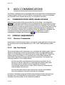
5
ASCII COMMUNICATIONS
5-1
5.1
COMMUNICATIONS WRITE ENABLE/DISABLE
5-1
5.2
PHYSICAL REQUIREMENTS
5-1
5.3
INDIVIDUAL PARAMETERS
5-7
5.4
ERROR RESPONSE
5-15
(iv)
O075-V1
PM-0075
1
INTRODUCTION
The 161 -DIN and 18-DIN Plastics Controllers are economical, microprocessor-based
temperature controller specially designed for use in plastics applications. They
incorporate the latest in surface-mount and CMOS technology. The standard
features include:
• Dual four-digit LED display (upper display red, lower display green).
• Thermocouple or three-wire RTD sensor input
• Relay, SSR drive (10V) or solid state Output 1.
• Input range selected from the front panel.
• Heater current “ammeter” on front panel. Can use a unique two-wire
“SCRi” connection to dedicated silicon controlled rectifier stacks. Also
supports standard four-wire connection via a separate current
transformer.
• Heater Break alarms (high, low and short-circuit) to cater for most
requirements.
• Unique “Quick Transfer” for easy set up of heater break alarms. This can
be initiated from the front panel, digital input or via the communications
link
• Soft Start with dedicated setpoint, timer and Output 1 power limit.
• Adjustable alarm hysteresis.
• 90 - 264V AC power supply.
• Certified to EN50081-1:1992 and EN50081-2:1994 (Emission) and to
EN50082-1:1992 and EN50082-2:1995 (Immunity) EMC specifications.
Complies with EN61010-1:1993 Safety Standard.
• Front panel sealing to IP66 (NEMA 4) standard.
• CE rated (UL pending).
• Auto/Manual Control and Auto/Zero Power
• Pre-Tune and Self-Tune.
• Setpoint ramping.
O075-4
1-1
PM-0075
• Programmable input filter.
• Alarm type selected from front panel.
• Sensor Break protection.
• Setpoint maximum and minimum limits (user-defined).
and its many optional features include:
• MODBUS and ASCII (selectable) communications with up to 128 zone
address capability.
• Output 2 - secondary (COOL) control output (relay, SSR drive or solid
state), Alarm 2 output, Heater Break alarm output or logical combination
of Alarm 1 and Alarm 2.
• Output 3 - Alarm 1 output, Heater Break Alarm output, DC recorder output
(setpoint or process variable) or logical combination of Alarm 1 and
Alarm 2.
• Output 4 - Heater Break Alarm output.
• Dual setpoint, remotely selectable.
NOTE: The communications option and the dual setpoint/quick
transfer option are mutually exclusive.
1.1
TAILORING THE CONTROLLER TO SUIT YOUR NEEDS
The Controller has three modes in which adjustments can be made via the front
panel keys:
Configuration Mode: This is normally used only when the Controller is
first configured or when a major change is to be made to the
Controller characteristics. Entry into this Mode is security-protected.
The Configuration Mode parameters should be set as required
before any other adjustments are made. Changing Configuration
Mode parameters invariably sets other parameters to their default
values. Adjustments to these parameters should be performed only
by personnel competent and authorised to do so.
Set Up Mode: This mode is used when a change to the process
set-up is required. The frequency of use for this mode is dependent
upon the process being controlled. This mode also determines the
scope of adjustments available in Operator Mode (see below).
Access to this mode is via a user-defined password.
1-2
O075-4
PM-0075
Operator Mode: This is the mode for day-to-day use. The parameters
in this mode are freely available to the operator. The adjustment
facilities available in this mode are dependent upon the settings of
parameters in the Set Up Mode.
1.2
HOW IT WORKS
The Plastics Controller is tailored towards plastics applications. The function of the
Controller is best described in terms of the control it exercises over the process
and the use of its alarms.
1.2.1
Control
The temperature at which the process must operate is called the setpoint (SP). The
actual process temperature which is being measured and controlled is called the
process variable (PV). Thus, if the setpoint is adjusted to 200°C, the Controller
endeavours to maintain the process variable at 200°C.
PID control (also known as three-term control) is a well-proven and widely-used
method for high accuracy automatic control. Best results are obtained when the
Controller is correctly tuned - easily achieved by just letting the Controller tune
itself to your process, using the automatic tuning features.
Heater current is controlled via Output 1. Although the heater can only be either
fully-on or fully-off, the process reacts only to the average power, assuming heater
on-off periods are sufficiently brief. The PID algorithm can control average power
very accurately, thereby ensuring smooth and accurate control of the process.
This method of controlling output power is very common and is known as
time-proportioning. An adjustable Cycle Time parameter determines the duration
of each on-off output cycle. Longer cycle times prolong mechanical relay
contact life; shorter cycle times (normally using solid state relays) will be needed
on processes which react more quickly. Output 2 can be used as a cooling
output, if required.
The Controller has a special Soft Start feature, used when a gentle start-up phase
is required in order to avoid damage to the process. An adjustable Soft Start
Setpoint is used by the Controller during a Soft Start. The duration of the Soft Start
phase is determined by an adjustable Soft Start Time parameter. During this
phase, Ouput 1 power is kept within an adjustable limit and the Output 1 cycle
time is reduced to a quarter of its normal value (but never less than 0.5 seconds)
to reduce further the risk of thermal shock to the process.
The Controller can be put into Manual Control if selected by the operator. In this
mode, the operator adjusts manually the Controller’s output power. When
switching between automatic control and manual control, the Controller
minimises any sudden power changes; this is known as a “bumpless transfer” and
avoids thermal shocks to the process. Manual Control mode can be configured to
be a non-adjustable zero power value or disabled completely.
O075-4
1-3
PM-0075
1.2.2
Alarms
Alarms allow early warning (and automatic corrective action, if necessary) in the
event of abnormal process conditions - heater failure, sensor failure, human error
etc. In addition to giving visual indication of such conditions, alarms can be
connected to outputs; the Controller can intervene automatically as soon as it
detects a problem in the plant.
Two standard alarms are provided which warn if the process variable temperature
moves outside prescribed limits. These alarms can be set to react if the process
variable goes above or below specific temperatures or moves too far away from
the setpoint. In the latter case, the alarm settings need no re-adjustment if the
setpoint is changed.
Heater break alarms allow prompt detection of heater failure, minimising the risk
of damage to the process. Three different types of alarm are provided, permitting
the majority of heater failures to be handled effectively. The actual heater current
can be displayed on the front panel.
1-4
O075-4
PM-0075
2
2.1
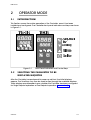
OPERATOR MODE
INTRODUCTION
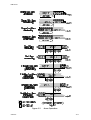
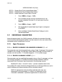
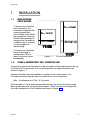
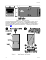
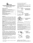
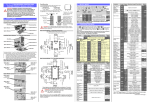
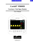
This Section covers the routine operation of the Controller, once it has been
installed and configured. The Controller front panel indicators and keys are shown
in Figure 2-1.
Figure 2-1
2.2
Front Panel Indicators and Control Keys
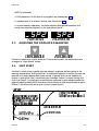
SELECTING THE PARAMETER TO BE
DISPLAYED/ADJUSTED
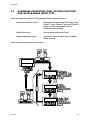
After the Controller has performed its power-up self-test, the initial displays
appear. The Scroll key may then be used to step through the available displays.
These displays are dependent upon whether the Controller has been configured
for Single Setpoint operation or Dual Setpoint operation (see overleaf).
O075-2
2-1
PM-0075
NOTES
1. Setpoint is not adjustable if Setpoint Strategy = 1 (see Subsection 3.2.40)
but is adjustable if Setpoint Strategy = 2. Active setpoint is one of: Setpoint,
Setpoint 1, Setpoint 2 or Soft Start Setpoint, as appropriate.
2. Appears only if setpoint ramping is enabled and ramp rate is in the
range 1 - 9999.
3. Ramp rate is adjustable in the range 1 - 9999 (On) and Off (blank).
2-2
O075-2
PM-0075
NOTES (continued)
4. Only appears if a Soft Start is in progress; see Subsection 2.4.
5. Appears only if an alarm is active; see Subsection 2.6.
6. In dual setpoint operation, the lower display distinguishes between the
active and inactive setpoints in the following manner:
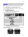
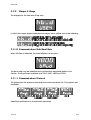
2.3
ADJUSTING THE DISPLAYED PARAMETER
If either of these keys is held down for 10 seconds or more, the adjustment rate
changes to “high speed” mode.
2.4
SOFT START
Soft Start is used when a gentle start-up phase is required, before going to full
working temperature. During Soft Start, a dedicated setpoint is used to control the
process to a lower temperature than normal. A power limit can be applied to
Output 1 during Soft Start, constraining the average Output 1 power. During Soft
Start, the Output 1 cycle time is automatically reduced to give added protection
against thermal shock (NOTE: because of the nature of time-proportioned outputs,
Output 1 will still be fully-on for part of each output cycle).
O075-2
2-3
PM-0075
Soft Start Time, Soft Start Setpoint and power limit are all adjustable in Set Up Mode
(see Section 3). Soft Start is aborted at start-up if the process variable exceeds the
Soft Start Setpoint. Setpoint ramping is inhibited during Soft Start. During a Soft
Start, the Soft Start time remaining at any moment may be read from the front
panel.
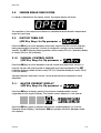
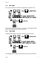
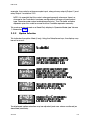
2.5
INDICATION OF AN ALARM GOING ACTIVE
If any of the Heater Break Alarms (High, Low or Short Circuit), Alarm 1 or Alarm 2
goes active, the HB/AL indicator will flash.
2.6
ALARM STATUS DISPLAY
(available if one or more alarms are active)
The alarm status display is in the following format:
2.7
OVER-RANGE/UNDER-RANGE DISPLAYS
If the process variable goes under-range or over-range, the upper display will
show the appropriate one of:
2-4
O075-2
PM-0075
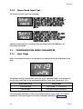
2.8
SENSOR BREAK INDICATION
If a break is detected in the sensor circuit, the upper display will show:
The reaction of the outputs and alarms to a detected sensor break is dependent
upon the input type.
2.9
OUTPUT TURN OFF
(AM Key Usage Set Up parameter =
)
Press the AM key to switch between automatic control and the control output(s)
being permanently turned off. A return to automatic control is via a bumpless
transfer. The SET indicator flashing pattern will be mostly OFF (if in Operator Mode)
or mostly ON (if in Set Up Mode).
2.10
MANUAL CONTROL MODE
(AM Key Usage Set Up parameter =
)
Press the AM key to switch between manual control and automatic control. In
manual control, the output power is displayed and may be adjusted. The SET
indicator flashing pattern will be mostly OFF (if in Operator Mode) or mostly ON (if
in Set Up Mode).
Transfer between automatic control and manual control is bumpless in both
directions.
2.11
HEATER CURRENT DISPLAY
(AM Key Usage Set Up parameter =
)
Press the AM key to display quickly the process variable/heater current,
regardless of the original display. The heater current display is in the format:
Press the AM key again to display the process variable/setpoint (i.e. the first
Operator Mode display). Subsequent AM key presses will switch between these
two displays.
O075-2
2-5
PM-0075
2.12
SOFT START IN PROGRESS
If a Soft Start is in progress, the heater current display will show (in the lower
display):
The normal heater current display will be restored as soon as the Soft Start time
has expired.
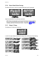
2.13
QUICK TRANSFER OF HEATER CURRENT TO
NOMINAL VALUE
The nominal value of the heater current is manually adjustable in Set Up Mode.
However, to set the nominal value to the prevailing heater current value in
Operator Mode:
2-6
O075-2
PM-0075
2.14
PRE-TUNE
To tune approximately the Controller’s PID parameters, activate Pre-Tune:
The AT indicator will flash whilst Pre-Tune is operating. To dis-engage Pre-Tune,
repeat this procedure (the AT indicator will go OFF).
2.15
SELF-TUNE
To optimise tuning whilst the Controller is operating, activate Self-Tune:
To dis-engage Self-Tune, repeat this procedure (the AT indicator will go OFF).
O075-2
2-7
PM-0075
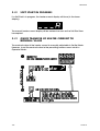
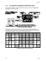
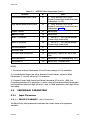
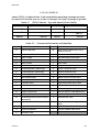
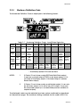
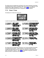
2.16
TO VIEW THE HARDWARE DEFINITION CODE
The Hardware Definition Code indicates the input type and output type(s) fitted
(see below). To view this Code:
The same key action causes a return to the normal Operator Mode display. An
automatic return is made to the normal Operator Mode display after 30 seconds.
The Hardware Definition Code has the following significance:
Value
0
Input
Output
1
Not
Output fitted
2( & 4)
Not
Output fitted
3
1
2
RTD
Input
Thermocouple
Input
Relay
Output
SSR
Drive
Output
Solid
State
Output
Relay
Output
2
SSR
Drive
Output
2
Solid
State
Output
2
Relay
Output
3
DC
0-10V
Output
4
DC
0-20mA
Output
5
DC
0-5V
Output
7
DC
4-20mA
Output
8
9
Relay
Output
2&4*
Solid
State
Output
* Dual Relay Option PCB must be fitted
2-8
O075-2
PM-0075
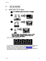
3
SET UP MODE
3.1
ENTRY INTO SET UP MODE
NOTE: If the upper display shows:
(i.e. all decimal point positions ON), parameters are at their default values,
possibly due to a change in Controller configuration. To cancel this
indication, adjust any Set Up Mode parameter (see below). It is
recommended that all configuration parameters are finalised before any
adjustments are made to Set Up Mode parameters.
O075-3
3-1
PM-0075
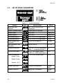
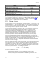
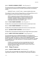
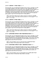
3.2
SET UP MODE PARAMETERS
Table 3-1
Parameter
Legend
Set Up Parameters
Adjustment Range
Default
Input Filter Time
Constant
OFF, 0.5s to 100.0s In 0.5s
increments
2.0s
Process Variable Offset
±input span of Controller
0
Output Power
0 to 100%
Read Only
0 to 100%
Read Only
0.0% to 999.9% of input span
10.0%
0.0% to 999.9% of input span
10.0%
Reset (Integral Time
Constant) 1
1s to 99m 59s and OFF.
5m 00s
Rate (Derivative Time
Constant) 1
00s to 99m 59s
1m 15s
−20% to + 20% of Proportional
Band 1 + Proportional Band 2
0%
0% to 100% (single output)
−100% to +100% (dual output)
25%
0.1% to 10% of input span
0.5%
Setpoint High Limit
Setpoint to Range Max.
Range
Max.
Setpoint Low Limit
Range Min. To Setpoint
Range
Min.
Output Power 2
4
Proportional Band 1
Proportional Band 2
Overlap/Deadband
Manual Reset (Bias)
1, 4
1, 4
1
ON/OFF Differential 2 :
Output 1 only
3-2
Output 2 only
4
Outputs 1 & 2
4
O075-3
PM-0075
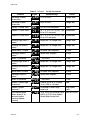
Table 3-1 (Cont.)
Parameter
Legend
Set Up Parameters
Adjustment Range
Default
Recorder Output
Scale Max.
−1999 to 9999
Range Max.
Recorder Output
Scale Min.
-1999 to 9999
Range Min.
0 to 100% of full power
100%
1
Output 1 Power Limit
Output 1 Cycle Time
0.5, 1, 2, 4, 8, 16, 32, 64, 128, 32seconds
256 or 512 seconds
Output 2 Cycle Time
0.5, 1, 2, 4, 8, 16, 32, 64, 128, 32seconds
256 or 512 seconds
Process High Alarm 1
value 3
Range Min. To Range Max.
Range Max.
Process Low Alarm 1
value 3
Range Min. To Range Max.
Range Min.
0 to span from Setpoint
5 units
Deviation Alarm 1
value 3
±span from Setpoint
5 units
Alarm 1 Hysteresis
1 - 250 units
1 unit
Process High Alarm 2
value 3
Range Min. To Range Max.
Range Max.
Process Low Alarm 2
value 3
Range Min. To Range Max.
Range Min.
0 to span from Setpoint
5 units
Deviation Alarm 2
value 3
±span from Setpoint
5 units
Alarm 2 Hysteresis
1 - 250 units
1 unit
Heater Current High
ScaleLimit
10.0A to 20.0A in 0.1A steps
21A to 100A in 1A steps
50A
Heater Current
Nominal 9
0 to Heater Current High
Scale Limit
High Scale
Limit
Low Heater Break
Alarm level (% or
amount below
nominal heater
current)
1% to 100% (of nominal) and
0 (OFF) or 0.1A/1A to Heater
Current High Scale Limit
20% or 0 (OFF)
Band Alarm 1 value
Band Alarm 2 value
O075-3
3
3
3-3
PM-0075
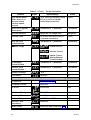
Table 3-1 (Cont.)
Parameter
Legend
Set Up Parameters
Adjustment Range
Default
High Heater Break
Alarm level (% or
amount above
nominal heater
current)
1% to 100% (of nominal) and 0
(OFF) or 0.1A/1A to Heater
Current High Scale Limit
0 (OFF)
Short Circuit Heater
Break Alarm 10
0 (disabled) or 1 (enabled)
1 (enabled)
Soft Start Setpoint
Range Min. To Range Max.
Range Min.
Soft Start Time
15s to 59m 45s and 0 (OFF) in
15-second increments
0 (OFF)
Auto Pre-Tune
Enable/Disable
0 (disabled) or 1 (enabled)
0 (disabled)
AM Key Usage
Output Turn-off
Manual Control
Heater Current
display/Manual
Control Disable
SP Ramping
Enable/Disable
0 (disabled) or 1 (enabled)
0 (disabled)
0 (disabled) or 1 (enabled)
1 (enabled)
Setpoint Strategy
1 or 2
1
Lock Value
0 to 9999
10
Comms. Write
Enable/Disable
6
OPERATOR MODE DISPLAYS (still accessible in Set Up Mode)
PV/Active SP
See Subsection 2.2
-
PV/Heater Current
Read Only
-
SPHi to SPLo
SPLo
SPHi to SPLo
SPLo
Read Only
-
1 to 9999 and OFF
OFF
Soft Start Time
Remaining
Read Only
-
Alarm Status
Read Only (see Subsection 2.6)
-
SP or SP1
8
SP2 (Dual SP only)
Ramping SP value
SP Ramp Rate
3-4
7
5
O075-3
PM-0075
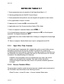
NOTES ON TABLE 3-1
1. These parameters are not operative if the Proportional Band = 0.
2. Switching differential with ON/OFF Control Output.
3. These parameters are optional; only one legend will appear for each alarm.
4. Only applicable if Output 2 is fitted.
5. Appears only if ramp rate rp is not switched OFF.
6. Applicable only if the Communications Option PCB is fitted.
7. Does not appear in Operator Mode unless rPEN = 1.
8. For Single Setpoint operation, the legend displayed is SP; for Dual Setpoint
operation, the legend displayed is SP1.
9. Applicable only when Heater Break Alarm Strategy is configured to Percentage
Mode.
10. Does not appear if Heater Break Input Type is configured to be SCRi.
3.2.1
Input Filter Time Constant
The Controller input is equipped with a digital filter which is used to filter out any
extraneous impulses on the process variable. This filtered PV is used for all
PV-dependent functions (control, alarms etc.). The time constant for this filter may
be adjusted in the range 0.0 seconds (filter OFF) to 100.0 seconds in 0.5 second
increments. The default setting is 2.0 seconds.
CAUTION: If this parameter is set to an excessively high value, the control
quality may be significantly impaired. The value chosen should be
sufficiently large to attenuate stray noise on the process variable signal but
no larger.
3.2.2
Process Variable Offset
This parameter is used to modify the actual process variable value (measured at
the Controller’s input terminals) in the following manner:
Offset PV value = Actual PV value + Process Variable Offset value.
O075-3
3-5
PM-0075
The offset process variable value is used for all PV-dependent functions (control,
display, alarm, recorder output etc.).
NOTE: This parameter value should be chosen with care. Any
adjustment to this parameter is, in effect, a calibration adjustment.
Injudicious application of values to this parameter could lead to the
displayed process variable value bearing no meaningful
relationship to the actual process variable value. There is no front
panel indication when this parameter is in effect (i.e. has been set to
a non-zero value).
The default value is 0.
3.2.3
Output Power 1
This parameter is the current Output 1 power level. It is a “Read Only” parameter
and is not adjustable.
3.2.4
Output Power 2
This parameter is the current Output 2 power level (if Output 2 is fitted). It is a
“Read Only” parameter and is not adjustable. If Output 2 is not fitted, this
parameter display is not applicable.
3.2.5
Proportional Band 1
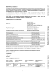
This parameter is the portion of the input span of the Controller over which the
Output 1 power level is proportional to the displayed process variable value. It
may be adjusted in the range 0.0% (i.e. ON/OFF control) to 999.9%. The default
value of this parameter is 10.0%. The function of the Proportional Band 1 is
illustrated in Figure 3-1.
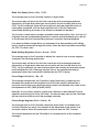
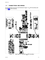
3.2.6
Proportional Band 2
This parameter is the portion of the input span of the Controller over which the
Output 2 power level is proportional to the displayed process variable value. It
may be adjusted in the range 0.0% (i.e. ON/OFF control) to 999.9%. The default
value of this parameter is 10.0%. This parameter is applicable only if Output 2 is
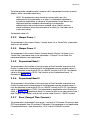
fitted. In Figure 3-1, Proportional Band 2 is shown (a) with a non-zero value (Case 1
and Case 2) - PID control, and (b) with a zero value (Case 3) - ON/OFF control.
3.2.7
Reset (Integral Time Constant)
This parameter is adjustable in the range 1 second to 99 minutes 59 seconds and
OFF (value greater than 99 minutes 59 seconds). This parameter is not applicable
if Proportional Band 1 (see Subsection 3.2.5) is set to 0 (ON/OFF control).
3-6
O075-3
PM-0075
Figure 3-1
O075-3
Proportional Band and Deadband/Overlap
3-7
PM-0075
3.2.8
Rate (Derivative Time Constant)
This parameter is adjustable in the range 00 seconds to 99 minutes 59 seconds.
This parameter is not applicable if Proportional Band 1 (see Subsection 3.2.5) is set
to 0 (ON/OFF control).
3.2.9
Overlap/Deadband
This defines the portion of the Proportional Band (Proportional Band 1 +
Proportional Band 2) over which both outputs are active (or, in the case of a
deadband, neither output is active). It is adjustable within the range –20% to
+20% (negative value = deadband). The default value is 0%. The function of the
overlap/deadband is illustrated in Figure 3-1. This parameter is not applicable if
Proportional Band 1 = 0 or if Output 2 is not fitted.
Note that, with Output 2 set to ON/OFF control (Figure 3-1 Case 3), the
Overlap/Deadband parameter has the effect of moving the ON Differential band
of Output 2 to create an overlap (positive values) or a deadband (negative
values). When Overlap/Deadband = 0, the “Output 2 OFF” edge of the Output 2
ON/OFF Differential band coincides with the point at which Output 1 reaches 0%.
3.2.10 Bias (Manual Reset)
This bias to the output power is expressed as a percentage of output power and is
adjustable in the range 0% to 100% (if only Output 1 is fitted) or –100% to +100%
(if both outputs are fitted). Its default value is 25%. This parameter is not
applicable if Proportional Band 1 = 0.
3.2.11 ON/OFF Differential (Hysteresis)
This is a switching differential used when one or both outputs have been set to
ON/OFF control (i.e. Proportional Band 1 or Proportional Band 2 or both = 0). This
parameter may be adjusted within the range 0.1% to 10.0% of the input span of
the Controller. The default value is 0.5%.
3.2.12 Setpoint High Limit
This is the maximum limit for setpoint adjustment. It should be set to a value which
prevents the setpoint being given a value which will cause damage to the
process being controlled. The Setpoint High Limit may be adjusted between the
current setpoint value and Input Range Maximum. The default value is Input
Range Maximum.
3.2.13 Setpoint Low Limit
This is the minimum limit for setpoint adjustment. It should be set to a value which
prevents the setpoint being given a value which will cause damage to the
3-8
O075-3
PM-0075
process being controlled. The Setpoint Low Limit may be adjusted between the
Input Range Minimum and the current setpoint value. The default value is Input
Range Minimum.
3.2.14 Recorder Output Scale Maximum
This parameter defines the value of process variable or setpoint (whichever is
applicable) at which the Recorder Output reaches its maximum value; for
example, for a 0 - 5V Recorder Output, this value corresponds to 5V. It may be
adjusted within the range –1999 to 9999. The decimal point position for the
Recorder Output is always the same as that for the process variable input range.
The default value is Input Range Maximum. This parameter is not applicable if the
Recorder Output option is not fitted.
NOTE: If this parameter is set to a value less than that for the Recorder
Output Scale Minimum (see Subsection 3.2.15), the relationship between
the process variable/setpoint value and the Recorder Output is reversed.
3.2.15 Recorder Output Scale Minimum
This parameter defines the value of the process variable or setpoint (whichever is
applicable) at which the Recorder Output reaches its minimum value; for
example, for a 0 - 5V Recorder Output, this value corresponds to 0V. It may be
adjusted within the range –1999 to 9999. The decimal point position for the
Recorder Output is always the same as that for the process variable input range.
The default value is Input Range Minimum. This parameter is not applicable if the
Recorder Output option is not fitted.
NOTE: If this parameter is set to a value greater than that for the Recorder
Output Scale Maximum (see Subsection 3.2.14), the relationship between
the process variable value and the Recorder Output is reversed.
3.2.16 Output 1 Power Limit
This parameter is used to limit the power level of Output 1 and may be used to
protect the process being controlled. If no protection is required, this parameter
may be set to 100% (the default value). It may be adjusted between 0% and
100%. This parameter is not applicable if Proportional Band 1 is set to 0.
If Soft Start is used, this power limit is applicable ony during Soft Start. When Soft
Start is completed, Output 1 power can go to 100%.
3.2.17 Output 1 Cycle Time
The cycle time value required is dependent upon the process being controlled
and the type of output being used for Output 1. For a Relay Output, the cycle
time should be as large as possible (whilst remaining compatible with the process
O075-3
3-9
PM-0075
control requirements) in order to maximise relay life. For an SSR Drive Output, the
cycle time may have a lower value (and thus satisfy the requirements of a
fast-changing process variable e.g. flow or pressure). The permitted range of
values is:
0.5, 1, 2, 4, 8, 16, 32, 64, 128, 256 or 512 seconds
The default value is 32 seconds. This parameter is not applicable if Proportional
Band 1 is set to 0.
3.2.18 Output 2 Cycle Time
The cycle time value required is dependent upon the process being controlled
and the type of output being used for Output 2. For a Relay Output, the cycle
time should be as large as possible (whilst remaining compatible with the process
control requirements) in order to maximise relay life. For an SSR Output, the cycle
time may have a lower value (and thus satisfy the requirements of a fast-changing
process variable e.g. flow or pressure). The permitted range of values is:
0.5, 1, 2, 4, 8, 16, 32, 64, 128, 256 or 512 seconds
The default value is 32 seconds. This parameter is not applicable if Proportional
Band 1 or Proportional Band 2 is set to 0.
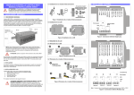
3.2.19 Process High Alarm 1 Value
This parameter, applicable only when Alarm 1 is selected to be a Process High
alarm, defines the process variable value at or above which Alarm 1 will be
active. Its value may be adjusted between Input Range Maximum and Input
Range Minimum. Its default value is Input Range Maximum. The operation of a
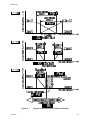
process high alarm is illustrated in Figure 3-2.
3.2.20 Process Low Alarm 1 Value
This parameter, applicable only when Alarm 1 is selected to be a Process Low
alarm, defines the process variable value at or below which Alarm 1 will be
active. Its value may be adjusted between Input Range Maximum and Input
Range Minimum. Its default value is Input Range Minimum. The operation of a
process low alarm is illustrated in Figure 3-2.
3.2.21 Band Alarm 1 Value
This parameter, applicable only if Alarm 1 is selected to be a Band Alarm, defines
a band of process variable values, centred on the setpoint value. If the process
variable value is outside this band, the alarm will be active. This parameter may
be adjusted to be within ±(input span) from the setpoint. The default value is five
input units. The operation of a band alarm is illustrated in Figure 3-2.
3-10
O075-3
PM-0075
Figure 3-2
O075-3
Alarm Operation
3-11
PM-0075
3.2.22 Deviation (High/Low) Alarm 1 Value
This parameter, applicable only if Alarm 1 is selected to be a Deviation High/Low
Alarm, defines a value above (positive value - Deviation High alarm) or below
(negative value - Deviation Low alarm) the setpoint; if the process variable
deviates from the setpoint by a margin greater than that defined by this
parameter, Alarm 1 goes active. This parameter value may be adjusted in the
range ±(input range) from setpoint. The default value is five input range units. The
operation of Deviation Alarms is illustrated in Figure 3-2.
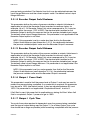
3.2.23 Alarm 1 Hysteresis
This parameter applies a hysteresis band on the “safe” side of the Alarm 1 value.
Thus, Alarm 1 will become active when the Alarm 1 value is exceeded; Alarm 1
will become inactive when the process variable value is outside the hysteresis
band on the “safe” side of the Alarm 1 value. Alarm 1 Hysteresis may be set to a
value in the range 1 - 250 or 0.1 - 25.0 (as per input resolution). The effect of the
hysteresis value on the operation of the different types of alarm is illustrated in
Figure 3-3.
3.2.24 Process High Alarm 2 Value
This parameter, applicable only when Alarm 2 is selected to be a Process High
alarm, defines the process variable value at or above which Alarm 2 will be
active. Its value may be adjusted between Input Range Maximum and Input
Range Minimum. Its default value is Input Range Maximum. The operation of a
process high alarm is illustrated in Figure 3-2.
3.2.25 Process Low Alarm 2 Value
This parameter, applicable only when Alarm 2 is selected to be a Process Low
alarm, defines the process variable value at or below which Alarm 2 will be
active. Its value may be adjusted between Input Range Maximum and Input
Range Minimum. Its default value is Input Range Minimum. The operation of a
process low alarm is illustrated in Figure 3-2.
3.2.26 Band Alarm 2 Value
This parameter, applicable only if Alarm 2 is selected to be a Band Alarm, defines
a band of process variable values, centred on the setpoint value. If the process
variable value is outside this band, the alarm will be active. This parameter may
be adjusted to be within ±(input span) from the setpoint. The default value is five
input units. The operation of a band alarm is illustrated in Figure 3-2.
3-12
O075-3
PM-0075
Figure 3-3
O075-3
Alarm Hysteresis Operation
3-13
PM-0075
3.2.27 Deviation (High/Low) Alarm 2 Value
This parameter, applicable only if Alarm 2 is selected to be a Deviation High/Low
Alarm, defines a value above (positive value - Deviation High alarm) or below
(negative value - Deviation Low alarm) the setpoint; if the process variable
deviates from the setpoint by a margin greater than that defined by this
parameter, Alarm 2 goes active. This parameter value may be adjusted in the
range ±(input range) from setpoint. The default value is five input range units. The
operation of Deviation Alarms is illustrated in Figure 3-2.
3.2.28 Alarm 2 Hysteresis
This parameter applies a hysteresis band on the “safe” •side of the Alarm 2 value.
Thus, Alarm 2 will become active when the Alarm 2 value is exceeded; Alarm 2
will become inactive when the process variable value is outside the hysteresis
band on the “safe” side of the Alarm 2 value. Alarm 2 Hysteresis may be set to a
value in the range 1 - 250 or 0.1 - 25.0 (as per input resolution). The effect of the
hysteresis value on the operation of the different types of alarm is illustrated in
Figure 3-3.
3.2.29 Heater Current High •Scale Limit
This parameter defines the full scale value for the heater current range. It may be
adjusted from 10.0A to 20.0A in 0.1A increments, and then from 21A to 100A in 1A
increments. The default value is 50A. Heater current range minimum is fixed at
0A. This value also determines the Short Circuit Heater Break Alarm level (see
below).
NOTE: If this parameter value is changed, the Heater Nominal Current, Low
Heater Break Alarm Value and High Heater Break Alarm Value parameters
are set to their default values (see Table 3-1).
3.2.30 Heater Nominal Current
This parameter defines a nominal value for the heater current and is only
applicable if Heater Break Alarm Strategy is configured to Percentage Mode. It
may be adjusted in the range 0A to Heater Current High Scale Limit. The default
value is the Heater Current High Scale Limit. It can also be set automatically (in
Operator Mode or Set Up Mode) to the heater current value at any instant by
using “Quick Transfer” (see Subsection 2.13).
3.2.31 Low Heater Break Alarm Value
The Controller monitors two current values: ON-current (when Output 1 is on) and
OFF-current (when Output 1 is off). This parameter defines a heater ON-current
value below which the Low Heater Break Alarm will become active. It may be
adjusted in the following ranges below the heater current nominal value:
3-14
O075-3
PM-0075
If Heater Break Alarm Strategy = Percentage Mode: 0 - 100% of
Heater Nominal Current (0 = OFF - value display blank, Low Heater
Alarm forced inactive). Default value = 20% below heater nominal
current. Hysteresis is half the Low Heater Break Alarm value.
If Heater Break Alarm Strategy = Absolute Mode: 0.1A/1A
(dependent upon display resolution) - Heater Current High Scale
Limit and 0 (OFF) - value display blank, Low Heater Alarm forced
inactive. Default value = 0 (OFF). Hysteresis is 0.5A for 0.1A resolution
and 2A for 1A resolution.
3.2.32 High Heater Break Alarm Value
The Controller monitors two current values: ON-current (when Output 1 is on) and
OFF-current (when Output 1 is off). This parameter defines a heater ON-current
value above which the High Heater Break Alarm will become active. It may be
adjusted in the following ranges above the heater current nominal value:
If Heater Break Alarm Strategy = Percentage Mode: 0 - 100% of
Heater Nominal Current (0 = OFF - value display blank, High Heater
Alarm forced inactive). Default value is 0 (OFF). Hysteresis is half the
High Heater Break Alarm value.
NOTE: Unless the High Heater Break Alarm is set OFF, if the heater current
exceeds the Heater Current High Scale Limit, the High Heater Break Alarm
will be forced active, even if the effective Alarm level is set higher than the
Heater Current High Scale Limit.
If Heater Break Alarm Strategy = Absolute Mode: 0.1A/1A
(dependent upon display resolution) - Heater Current High Scale
Limit and 0 (OFF) - value display blank, High Heater Alarm forced
inactive. Default value = 0 (OFF). Hysteresis is 0.5A for 0.1A resolution
and 2A for 1A resolution.
3.2.33 Short Circuit Heater Break Alarm Enable/Disable
This parameter enables/disables the Short Circuit Heater break Alarm (1
=enabled, 0 = disabled). The default setting is 1 (enabled). The Controller
monitors two current values: ON-current (when Output 1 is on) and OFF-current
(when Output 1 is off). The Short Circuit Heater Break Alarm becomes active if the
heater OFF-current exceeds 5% of Heater Current High Scale Limit. NOTE: This
parameter is not available if Heater Break Input Type is configured to be SCRi.
3.2.34 Soft Start Setpoint
The use and operation of Soft Start are described in Subsection 2.4. The value of
this parameter is adjustable (between Input Range Maximum and Input Range
Minimum) in Set Up Mode only and is in force for the duration of the Soft Start.
O075-3
3-15
PM-0075
When the Soft Start Time expires, the normal setpoint value is restored. Default
value is Input Range Minimum.
3.2.35 Soft Start Time
This parameter defines the duration of the Soft Start from power-up. After this time
expires, normal setpoint values will prevail. This parameter is adjustable in the
range 15 seconds to 59 minutes 45 seconds (in 15-second increments) and OFF
(less than 15 seconds); the default value is OFF.
3.2.36 Auto Pre-Tune Enable/Disable
This parameter determines whether or not Pre-Tune is activated automatically on
power-up or not (0 = Disabled, 1 = Enabled). The default setting is 0 (Disabled).
3.2.37 AM Key Usage
This parameter may be set to one of three options:
The default setting is Output Turn-Off.
3.2.38 Setpoint Ramp Enable/Disable
This parameter enables/disables use of the setpoint ramping feature at user level
(0 = Disabled, 1 = Enabled). The default setting is 0 (Disabled).
3-16
O075-3
PM-0075
3.2.39 Communications Write Enable/Disable
This parameter enables/disables Write operations (i.e. the changing of parameter
values/settings) via the RS485 communications link, if the Communications Option
PCB is fitted (0 = Disabled, 1 = Enabled). The default setting is 1 (Enabled).
Parameters can be interrogated via the link, regardless of the setting of this
parameter.
3.2.40 Setpoint Strategy
This parameter determines whether the active setpoint value shown in the
Operator Mode process variable/setpoint display is adjustable or not (1 = not
adjustable, 2 = adjustable). The default setting is 1. NOTE: During a Soft Start, the
active setpoint value cannot be altered, regardless of the setting of this
parameter.
3.2.41 Lock Value
This parameter defines the four-digit code required to enter Set Up Mode. It may
be adjusted in the range 0 to 9999. The default setting is 10.
3.3
OPERATOR MODE DISPLAYS
Once the complete cycle of Set Up Mode parameters has been displayed, the
user may then step through the Operator Mode displays (see Section 2), making
adjustments where required, before re-starting the Set Up Mode parameter cycle,
as shown in Table 3-1.
O075-3
3-17
PM-0075
3.4
TUNING THE CONTROLLER MANUALLY
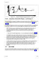
3.4.1
Controllers Fitted with Output 1 Only
Before starting to tune the Controller to the load, check that the Setpoint High and
Low Limits (SPhi and SPLo) are set to safe levels - see Subsections 3.2.12 and
3.2.13.
The following simple technique may be used to determine values for proportional
band (Pb1), derivative time constant (rAtE) and integral time constant (rSEt).
NOTE: This technique is suitable for use only with processes which are not
harmed by large fluctuations in the process variable. It provides an
acceptable basis from which to start fine tuning for a wide range of
processes.
1. Set the setpoint to the normal operating process value (or to a lower
value if overshoot beyond this value is likely to cause damage).
2. Select ON/OFF Control (i.e. set Pb1 = 0).
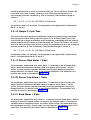
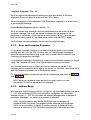
3. Switch on the process. Under these conditions, the process variable will
oscillate about the setpoint and the following parameter values should be
noted:
(a) The peak-to-peak variation (P) of the first cycle i.e. the difference
between the highest value of the first overshoot and the lowest value of the
first undershoot - see Figure 3-4)
(b) The cycle time (T) of this oscillation in minutes (see Figure 3-4)
4. The control parameters should then be set at follows:
=
P
X 100
ScaleRange
= T minutes
=
T
minutes
6
NOTE: After setting up the parameters, set the Controller to Operator
Mode (see Subsection 3.6) to prevent unauthorised adjustment to
the values.
3-18
O075-3
PM-0075
Figure 3-4
3.4.2
Manual Tuning Parameters (Output 1 only)
Controllers Fitted with Output 1 and Output 2
Before starting to tune the Controller to the load, check that the Setpoint High and
Low Limits (SPhi and SPLo) are set to safe levels - see Subsections 3.2.12 and
3.2.13.
The following simple technique may be used to determine values for proportional
band (Pb1), derivative time constant (rAtE) and integral time constant (rSEt).
NOTE: This technique is suitable for use only with processes which are not
harmed by large fluctuations in the process variable. It provides an
acceptable basis from which to start fine tuning for a wide range of
processes.
1. Tune the Controller using Output 1 only as described in Subsection 3.4.1.
2. Set Pb2 to the same value as Pb1 and monitor the operation of the
Controller in dual output mode. If there is a tendency to oscillate as control
passes into the Output 2 proportional band, increase the value of Pb2. If
the process appears to be over-damped in the region of the Output 2
proportional band, decrease the value of Pb2.
3. When values of proportional bands, integral time constant and derivative
time constant have been determined for tuning, if there is a “kick” as
control passes from one output to the other, set OL to a positive value to
introduce some overlap. Adjust the value of OL by trial and error until
satisfied.
3.5
SELF-TUNE
Once the Controller has been manually tuned, Self-Tune may be used in Operator
Mode to enhance further the response of the Controller (see Subsection 2.15).
O075-3
3-19
PM-0075
3.6
EXIT FROM SET UP MODE
To leave Set Up Mode, select the initial Operator Mode display (process
variable/setpoint) then depress the Raise and Function keys simultaneously,
whereupon the Controller will return to Operator Mode.
NOTE: An automatic return to Operator mode will be executed if there is no
key activity in Set Up Mode for two minutes.
3-20
O075-3
PM-0075
4
MODBUS RTU COMMUNICATIONS
The Plastics Controller may be equipped with two-wire RS485-compatible serial
communications, by which means communication may occur between the
Controller and a master device (e.g. a computer or terminal).
4.1
COMMUNICATIONS WRITE ENABLE/DISABLE
When Communications Write operations are enabled (in Set Up Mode - see
Subsection 3.2.39), the Controller parameters may be adjusted by the master
device via the serial communications link. If communications Writes are disabled,
the Controller will not adjust or change any parameters in response to commands
received from the master device and will send a negative acknowledgement in
response to such commands. Whether communications Writes are enabled or
disabled, the Controller will return the requested information in response to
interrogation from the master device.
4.2
4.2.1
PHYSICAL REQUIREMENTS
Character Transmission
The data format is fixed to be one start bit, eight data bits and one stop bit. The
Baud rate may be selected to be 1200, 2400, 4800 (default) or 9600 Baud. The
parity is selectable to be even, odd, or none.
4.2.2
Line Turn-round
The line turn-round timings adhere to the industry standard.
4.3
MODBUS RTU PROTOCOL
The standard RS485 Communications Option and the Enhanced RS485
Communications option both use the industry standard MODBUS protocol. The
following restrictions are imposed:
• Baud rates may be set to 1200, 2400, 4800 or 9600 Baud only.
• Support for multi-parameter Write operations is limited to support of the
Multi-Word Write Function (Number 16) but permits writing of one
parameter only per message.
• The multi-parameter Read operations support a maximum of 10
parameters per message.
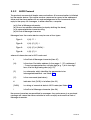
The following MODBUS functions are supported (JBUS names, where applicable,
are given in italics):
O075-4
4-1
PM-0075
Function
MODBUS Function Number
Read Coil Status (Read n Bits)
01/02
Read Holding Registers (Read n Words)
03/04
Force Single Coil (Write 1 Bit)
05
Preset Single Register (Write 1 Word)
06
Loopback Diagnostic Test
08
Preset Multiple Registers (Write n Words)
16
The Controller will identify itself in response to a Read Holding Registers message
which enquires the values of word parameters 121 and 122 (see Table 4-2);
MODBUS Function 17 (Report Slave ID) is not supported.
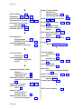
4.3.1
Message Formats
The first character of every message is the Controller address, in the range 1 - 128
(standard RS485) or 1 - 255 (enhanced RS485) and 0 for broadcast messages. The
second character is always the Function Number. The contents of the remainder
of the message depends upon this Function Number.
In most cases the Controller is required to reply to the message by echoing the
address and Function Number, together with an echo of all or part of the
message received (in the case of a request to write a value or carry out a
command) or the information requested (in the case of a Read Parameter
operation). Broadcast messages are supported at address 0 (to which the
Controller responds by taking some action without sending back any reply).
Data is transmitted as eight-bit binary bytes with one start bit, one stop bit and
optional parity checking (none, even or odd). A message is terminated simply by
a delay of more than three character lengths at the Baud rate used; any
character received after such a delay is considered to be the potential address
at the start of a new message.
Since only the RTU form of the protocol is supported, each message is followed by
a two-byte CRC 16 (a 16-bit cyclic redundancy checksum). This checksum is
calculated in accordance with a formula which involves recursive division of the
data by a polynomial, with the input to each division being the remainder of the
results of the previous division. The dividing polynomial is
2 16 + 2 15 + 2 2 + 1 (Hex 18005)
but this is modified in two ways:
(a) because the bit order is reversed, the binary pattern is also
reversed, making the most significant bit (MSB) the right-most bit, and
4-2
O075-4
PM-0075
(b) because only the remainder is of interest, the right-most (most
significant) bit can be discarded.
Thus, the polynomial has the value Hex A001. The CRC algorithm is shown in Figure
4-1.
Figure 4-1
O075-4
Cyclic Redundancy Check Algorithm
4-3
PM-0075
Read Coil Status (Read n Bits) - 01/02
The message sent to the Controller consists of eight bytes:
The normal reply will echo the first two characters of the message received
followed by a single-byte data byte count (which will not include itself or the
CRC). For this message, there will be one byte of data per eight bits-worth of
information requested, with the least significant bit of the first data byte
transmitted depicting the state of the lowest-numbered bit required.
This function is used mostly to report controller status information; thus, a bit set to 1
indicates that the corresponding feature is currently active/enabled and a bit set
to 0 indicates that the corresponding feature is currently inactive/disabled.
If an exact multiple of eight bits is not requested, the data padding with trailing
zeros is used to preserve the eight-bit format. After the data has been transmitted,
the CRC16 value is sent.
Read Holding Registers (Read n Words) - 03/04
The message sent to the Controller to obtain the value of one or more registers
comprises the following eight bytes:
The normal reply will echo the first two characters of the message received
followed by a single-byte data byte count (which will not include itself or the
CRC). For this message, the count value equals the number of parameter values
read multiplied by two. Following the byte count, the specified number of
parameter values are transmitted, followed by the CRC16 bytes:
Force Single Coil (Write 1 Bit) - 05
The message received by the Controller is eight bytes long, comprising the
standard pre-amble and the address of the bit to be forced, followed by a
two-byte word whose most significant byte contains the desired truth value of the
bit expressed as 0xFF (TRUE) or 0x00 (FALSE):
Normally, this function is used to control such features as Auto-Manual Control
selection and tuning (Pre-Tune, Self-Tune). The normal reply sent by the Controller
will be a byte-for-byte echo of the message received.
Preset Single Register (Write 1 Word) - 06
The message sent to the Controller comprises eight bytes: the address and
Function Number (as usual), the address of the parameter to be written, the
two-byte value to which the parameter is to be set and the CRC16 bytes:
The normal response from the Controller is a complete echo of the received
message.
4-4
O075-4
PM-0075
Loopback Diagnostic Test - 08
This is an eight-byte message comprising the usual pre-amble, a two-byte
diagnostic code, two bytes of data and the CRC16 bytes:
The only diagnostic code supported is 00. The normal response is an exact echo
of the received message.
Preset Multiple Registers (Write n Words) - 16
This is an eleven-byte message. only one parameter may be written for each
received message. The usual pre-amble is followed by the address of the
parameter to be written, a two-byte word count (always set to 1), a single-byte
byte count (always set to 2), the value to be written and the CRC16 bytes:
The Controller normally responds with the following eight-bit reply:
4.3.2
Error and Exception Responses
If a received message contains a corrupted character (parity check failure,
framing error etc.) or if the CRC16 check fails, or if the received message is
otherwise syntactically flawed (e.g. byte count or word count is incorrect), the
Controller will ignore that message.
If the received message is syntactically correct but nonetheless contains an illegal
value, the Controller will send a five-byte exception response as follows:
The Function Number byte contains the function number contained in the
message which caused the error, with its top bit set (i.e. Function 3 becomes 0x83)
and the Exception Number is on of the following codes:
For error and exception responses specific to a parameter, see notes in Table 4-1
and Table 4-2.
NOTE: Writing a parameter value equal to its current value is a valid
transaction; this will not cause an error response.
4.3.3
Address Range
With standard RS485 communications configured, the selectable address range is
1 - 128. With enhanced RS485 communications configured, the selectable
address range is 1 - 255. The Controller will respond appropriately to Address 0 broadcast messages - no matter what address is selected.
NOTE: The total receiver load on the RS485 link must not exceed 32
standard RS485 unit loads. This applies to both standard and enhanced
RS485 communications. A Plastics Controller presents 14 standard RS485
load, so a maximum of 128 Controllers are permitted. With other devices
O075-4
4-5
PM-0075
connected, the limit is dictated by the sum total of all the RS485 receiver
loadings.
4.3.4
Bit Parameters
The bit parameters are shown in Table 4-1.
4.3.5
Word Parameters
The word parameters are shown in Table 4-2.
4-6
O075-4
PM-0075
Table 4-1
Parameter
MODBUS Bit Parameters
No.
Notes
Comms. Write Status
1
Read Only. 1 = enabled, 0 = disabled
Auto/Manual Control
2
1 = Manual, 0 = Auto
4
3
1 = activate(d), 0 = dis-engage(d)
4
1 = activate(d), 0 = dis-engage(d)
Alarm 1 Status
5
Read Only. 1 = active, 0 = inactive
Alarm 2 Status
6
Read Only. 1 = active, 0 = inactive
Setpoint Ramp Enable/Disable
7
1 = enable(d), 0 = disable(d)
8
Read Only. 1 = change, 0 = no change
9
1 = Output Turn-Off, 0 = Auto Control
High Heater Break Alarm Status
10
Read Only. 1 = active, 0 = inactive
Low Heater Break Alarm Status
11
Read Only. 1 = active, 0 = inactive
Short-Circuit Heater Break
Alarm Status
12
Read Only. 1 = active, 0 = inactive
Heater Break Current Transfer
(Quick Transfer)
13
1 = initiate transfer, 0 = no transfer.
This bit will always be 0 when read.
Short-Circuit Heater Break
Alarm Enable/Disable
14
1 = enable(d), 0 = disable(d)
Reserved
15
Reserved
16
Self-Tune
Pre-Tune
5
Parameter Changed
Auto/Output Turn-Off
2
3
NOTES
1. Not available if AM Key Usage (see Subsection 3.2.37) is not set to Auto/Manual
Control Selection.
2. This indicates whether a parameter has been changed from the front panel
since the last interrogation via the communications link. Every interrogation of this
bit resets it to 0.
3. Not available if AM Key Usage (see Subsection 3.2.37) is not set to Auto/Output
Turn-Off Selection.
4. If Setpoint Ramping is enabled, an Activate Self-Tune command will not take
effect until the setpoint has reached its target value.
5. An Activate Pre-Tune command will fail if the process variable is within 5% of
input span from the setpoint.
6. Not available if Heater Break Input Type is configured to be SCRi.
7. Available only if Heater Break Alarm Strategy is set to Percentage Mode.
O075-4
4-7
PM-0075
Table 4-2
Parameter
MODBUS Word Parameters
No.
Notes
Process Variable
1
Read Only
Setpoint
2
Target setpoint if ramping
Output Power
3
Read Only if not in Manual Control mode
Arithmetic Deviation
4
Read Only
Proportional Band 2
5
Proportional Band 1
6
Status
7
Reset (Integral Time Constant)
8
Rate (Derivative Time Constant)
9
Output 1 Cycle Time
10
Scale Range Low
11 Read Only
Scale Range High
12 Read Only
Alarm 1 value
13
Alarm 2 value
14
Manual Reset (Bias)
15
Overlap/Deadband
16
ON/OFF Differential
17
Decimal Point Position
18 Read Only
Output 2 Cycle Time
19
Output 1 Power Limit
20
Control Setpoint value
21 Read Only - ramping setpoint if ramping
Setpoint High Limit
22
Setpoint Low Limit
23
Setpoint Ramp Rate
24
Input Filter Time Constant
25
Process Variable Offset
26
Recorder Output Maximum
27
Recorder Output Minimum
28
Heater Current High Scale Limit
29
Heater Nominal Current
30 Accessible only if Heater Break Alarm
Strategy is set to Percentage Mode
4-8
Read Only (see Table 4-1)
O075-4
PM-0075
Table 4-3
MODBUS Word Parameters (Cont.)
Parameter
No.
Notes
Low Heater Break Alarm value
31
0 - 100% and OFF or 0.1A/1A Heater Current High Scale Limit (see
Subsection 4.4.6.5)
High Heater Break Alarm value
32
0 - 100% and OFF or 0.1A/1A Heater Current High Scale Limit (see
Subsection 4.4.6.6)
Heater Current
33
Read Only
AM Key Usage
34
Read Only
Alarm 1 Hysteresis
35
1 - 250 or 0.1 - 25.0 (as per Heater
Current High Scale Limit)
Alarm 2 Hysteresis
36
1 - 250 or 0.1 - 25.0 (as per Heater
Current High Scale Limit)
Soft Start Setpoint
37
Soft Start Time
38
Soft Start Time Remaining
39
Read Only - Returns 0 if not in Soft
Start
Manufacturer ID
121
Read Only - 231 (representing “W1”)
Equipment ID
122
Read Only - number 6600
NOTES
1. The values of Word Parameters 29 and 30 are always to 0.1A resolution.
2. If Heater Break Alarms are set to Absolute Current Mode, values of Word
Parameters 31 and 32 will be to 0.1A resolution.
3. If Heater Current High Scale Limit (Word Parameter 29) is set to >20A, the
Controller operates to 1A resolution, in which case all the above Word Parameters’
least significant decimal digit will return ) and, in Write operations, that digit will be
truncated.
4.4
4.4.1
INDIVIDUAL PARAMETERS
Input Parameters
4.4.1.1 PROCESS VARIABLE - Word Parameter 1
This Read Only word parameter indicates the current value of the process
variable.
O075-4
4-9
PM-0075
4.4.1.2 PROCESS VARIABLE OFFSET - Word Parameter 26
This word parameter may be modified/interrogated. It modifies the actual process
variable value (as measured at the Controller’s input terminals) in the following
manner:
Modified PV value = Actual PV value + process variable offset value
The modified PV value is limited by Range Maximum and Range Minimum and is
used for display and alarm purposes and for recorder outputs.
NOTE: This parameter value should be selected with care. Any
adjustment to this parameter is, in effect, an adjustment to the
Controller’s calibration. Injudicious application of values to this
parameter could lead to the displayed PV value having no
meaningful relationship to the actual PV value.
4.4.1.3 SCALE RANGE MAXIMUM - Word Parameter 12
This Read Only word parameter indicates the maximum process input value.
4.4.1.4 SCALE RANGE MINIMUM - Word Parameter 11
This Read Only word parameter indicates the minimum process input value.
4.4.1.5 DECIMAL POINT POSITION - Word Parameter 18
This Read Only word parameter indicates the input range decimal point position.
4.4.1.6 INPUT FILTER TIME CONSTANT - Word Parameter 25
This word parameter may be modified/interrogated. The Controller input is
equipped with a digital filter which is used to filter out any extraneous impulses on
the process variable. This filtered PV is used for all PV-dependent functions
(control, alarms etc.). The time constant for this filter may be adjusted in the range
0.0 seconds (filter OFF) to 100.0 seconds in 0.5 second increments. The default
setting is 2.0 seconds.
CAUTION: If this parameter is set to an excessively high value, the
control quality may be significantly impaired. The value chosen
should be sufficiently large to attenuate stray noise on the process
variable signal but no larger.
4.4.2
Output Parameters
4.4.2.1 OUTPUT POWER VALUE - Word Parameter 3
The value of this word parameter may range between 0% and 100% (for a
single-output Controller) or –100% and 100% (for a dual-output Controller). If
4-10
O075-4
PM-0075
Manual control is not selected, this word parameter is Read Only; if Manual
control is selected, this parameter may be adjusted.
4.4.2.2 OUTPUT 1 POWER LIMIT - Word Parameter 20
This word parameter may be modified/interrogated. It defines the power limit for
Output 1 and may be set in the range 0% to 100% of full power. The default value
is 100%. The decimal point position is fixed at 1 decimal place. If Soft Start is used,
this power limit is applicable only during Soft Start. When Soft Start is completed,
Output 1 power can go to 100%.
4.4.2.3 OUTPUT 1 CYCLE TIME - Word Parameter 10
This parameter may be modified/interrogated. The value to which this is set is
dependent upon the output type and the nature of the process to be controlled.
For relay outputs, this parameter should be set to as large a value as possible
(consistent with satisfactory control of the process) in order that the life of the relay
be maximised. For SSR Drive and Solid State outputs, lower values may be used.
The decimal point position is set at 1 decimal place.
NOTE: Cycle Time values must be written correctly i.e. the value must
be a power of 2 in the range 0.5 - 512 (0.5, 1, 2, 4, 8, etc.).
4.4.2.4 OUTPUT 2 CYCLE TIME - Word Parameter 19
This parameter may be modified/interrogated. The value to which this is set is
dependent upon the output type and the nature of the process to be controlled.
For relay outputs, this parameter should be set to as large a value as possible
(consistent with satisfactory control of the process) in order that the life of the relay
be maximised. For SSR Drive and Solid State outputs, lower values may be used.
The decimal point position is set at 1 decimal place.
NOTE: Cycle Time values must be written correctly i.e. the value must
be a power of 2 in the range 0.5 - 512 (0.5, 1, 2, 4, 8, etc.).
4.4.2.5 RECORDER OUTPUT MAXIMUM VALUE - Word Parameter 27
This word parameter may be modified/interrogated. It defines the maximum value
for the Controller’s Recorder Output and may be adjusted within the range –1999
to 9999. This value corresponds to the Input Scale Maximum and the decimal
point position will always be the same as that for the input.
NOTE: If this parameter is set to a value less than the Recorder
Output Minimum Value, the sense of the Recorder Output is
reversed.
O075-4
4-11
PM-0075
4.4.2.6 RECORDER OUTPUT MINIMUM VALUE - Word Parameter 28
This word parameter may be modified/interrogated. It defines the minimum scale
value for the Controller’s Recorder Output and may be adjusted within the range
–1999 to 9999. This value corresponds to the Input Scale Minimum and the
decimal point position will always be the same as that for the input. If this
parameter is set to a value greater than the Recorder Output Maximum Value, the
sense of the Recorder Output is reversed.
4.4.3
Heater Current Parameters
4.4.3.1 HEATER CURRENT HIGH SCALE LIMIT - Word Parameter 29
This word parameter defines the full scale value for the heater currrent range. It
may be adjusted from 10.0A to 20.0A in 0.1A increments, and then from 21A to
100A in 1A increments. The default value is 50A. Heater current range minimum is
fixed at •0A.
NOTE: If this parameter value is changed, the Heater Nominal
Current, Low Heater Break Alarm Value and High Heater Break Alarm
Value parameters are set to their default values.
4.4.3.2 HEATER NOMINAL CURRENT - Word Parameter 30
This word parameter defines a nominal value for the heater current. It may be
adjusted in the range 0A to Heater Current High Scale Limit value. The default
value is the Heater Current High Scale Limit value. This parameter is accessible
only if Heater Break Alarm Strategy is configured to Percentage Mode.
4.4.3.3 HEATER CURRENT - Word Parameter 33
This Read Only word parameter indicates the most recent valid heater current
value at the instant the message is received; it is equivalent to calling up the
heater current display from the front panel.
4.4.4
Setpoint Parameters
4.4.4.1 SETPOINT VALUE - Word Parameter 2
This word parameter may be modified/interrogated. It can be set to any value
between Setpoint High Limit (see Subsection 4.4.4.3) and Setpoint Low Limit (see
Subsection 4.4.4.4). When the setpoint is ramping, this is the target setpoint value.
4.4.4.2 SETPOINT RAMP RATE - Word Parameter 24
This word parameter may be modified/interrogated. It defines the rate at which
the current setpoint can be made to ramp and can be set to a value in the range
4-12
O075-4
PM-0075
1 - 9999 increments per hour or 0 (ramping OFF). The decimal point position is as
for the input range.
4.4.4.3 SETPOINT HIGH LIMIT - Word Parameter 22
This word parameter may be modified/interrogated. It defines the maximum value
which may be assigned to the setpoint. The default value is Input Range
Maximum. The permissible range is between the current setpoint value and Input
Range Maximum. The decimal point position is as for the input range.
4.4.4.4 SETPOINT LOW LIMIT - Word Parameter 23
This word parameter may be modified/interrogated. It defines the minimum value
which may be assigned to the setpoint. The default value is Input Range Minimum.
It may be set to a value between Input Range Minimum and the current value of
the setpoint. The decimal point position is as for the input range.
4.4.4.5 CONTROL SETPOINT - Word Parameter 21
This Read Only word parameter is the setpoint value being used by the Controller
at the instant the message is received. When the setpoint is ramping, this is the
ramping setpoint value.
4.4.5
Soft Start Parameters
4.4.5.1 SOFT START SETPOINT - Word Parameter 37
This word parameter may be modified/interrogated. It defines the value of
setpoint to be used during a soft start. It may be adjusted between Input Range
Minimum and Input Range Maximum. The default value is Input Range Minimum.
4.4.5.2 SOFT START TIME - Word Parameter 38
This word parameter may be modified/interrogated. It defines the duration of the
Soft Start. It may be adjusted in 15-second increments within the range 0 (OFF) to
59 minutes 45 seconds. A value which is not an exact multiple of 15 seconds is
treated as an invalid value. The default value is 0 (OFF).
4.4.5.3 SOFT START TIME REMAINING - Word Parameter 39
This Read Only word parameter is the time remaining for a Soft Start at the instant
the message is received. When there is no Soft Start currently in effect, a value of
0 is returned.
O075-4
4-13
PM-0075
4.4.6
Alarm Parameters
4.4.6.1 ALARM 1 VALUE - Word Parameter 13
This word parameter may be modified/interrogated. It defines the level at which
Alarm 1 will go active. The decimal point position is as for the input range.
4.4.6.2 ALARM 1 HYSTERESIS - Word Parameter 35
This word parameter applies a hysteresis band on the "safe" side of the Alarm 1
value. Thus, Alarm 1 will become active when the Alarm 1 value is exceeded;
Alarm 1 will become inactive when the process variable value is outside the
hysteresis band on the “safe” side of the Alarm 1 value. Alarm 1 Hysteresis may be
set to a value in the range 1 - 250 or 0.1 - 25.0 (as per Heater Current High Scale
Limit). The effect of the hysteresis value on the operation of the different types of
alarm is illustrated in Figure 3-3.
4.4.6.3 ALARM 2 VALUE - Word Parameter 14
This word parameter may be modified/interrogated. It defines the level at which
Alarm 2 will go active. The decimal point position is as for the input range.
4.4.6.4 ALARM 2 HYSTERESIS - Word Parameter 36
This word parameter applies a hysteresis band on the “safe” side of the Alarm 2
value. Thus, Alarm 2 will become active when the Alarm 2 value is exceeded;
Alarm 2 will become inactive when the process variable value is outside the
hysteresis band on the “safe” side of the Alarm 2 value. Alarm 2 Hysteresis may be
set to a value in the range 1 - 250 or 0.1 - 25.0 (as per Heater Current High Scale
Limit). The effect of the hysteresis value on the operation of the different types of
alarm is illustrated in Figure 3-3.
4.4.6.5 LOW HEATER BREAK ALARM VALUE - Word Parameter 31
This word parameter defines a heater current value below which the Low Heater
Break Alarm will become active. It may be adjusted in the following ranges below
the Heater Nominal Current:
If Heater Break Alarm Strategy = Percentage Mode: 0 - 100% of
Heater Nominal Current (0 = OFF - value display blank, Low Heater
Alarm forced inactive). Default value = 20% below heater nominal
current. Hysteresis is half the Low Heater Break Alarm value.
If Heater Break Alarm Strategy = Absolute Mode: 0.1A/1A
(dependent upon display resolution) - Heater Current High Scale
Limit and 0 (OFF) - value display blank, Low Heater Alarm forced
inactive. Default value = 0 (OFF). Hysteresis is 0.5A for 0.1A resolution
and 2A for 1A resolution.
4-14
O075-4
PM-0075
4.4.6.6 HIGH HEATER BREAK ALARM VALUE - Word Parameter 32
This word parameter defines a heater current value above which the High Heater
Break Alarm will become active. It may be adjusted in the following ranges above
the Heater Nominal Current:
If Heater Break Alarm Strategy = Percentage Mode: 0 - 100% of
Heater Nominal Current (0 = OFF - value display blank, High Heater
Break Alarm forced inactive). Default value = 0 (OFF). Hysteresis is
half the High Heater Break Alarm value.
NOTE: Unless the High Heater Break Alarm is set OFF, if the heater current
exceeds the Heater Current High Scale Limit, the High Heater Break Alarm
will be forced active, even if the High Heater Break Alarm level is set higher
than the Heater Current High Scale Limit.
If Heater Break Alarm Strategy = Absolute Mode: 0.1A/1A
(dependent upon display resolution) - Heater Current High Scale
Limit and 0 (OFF) - value display blank, High Heater Break Alarm
forced inactive. Default value = 0 (OFF). Hysteresis is 0.5A for 0.1A
resolution and 2A for 1A resolution.
4.4.7
Tuning Parameters
4.4.7.1 RATE (DERIVATIVE TIME CONSTANT) - Word Parameter 9
This word parameter may be modified/interrogated. It defines the derivative time
constant for the control algorithm. The decimal point is used as the separator
between the minutes and seconds digits (i.e. set to 2 decimal places); the
decimal point position must be as described, otherwise modification will not
occur.
4.4.7.2 RESET (INTEGRAL TIME CONSTANT) - Word Parameter 8
This word parameter may be modified/interrogated. The {DATA} element is in a
format in which the first two digits represent minutes and the second two digits
represent seconds. The decimal point position complies with this format and the
decimal point is used as a separator between the minutes digits and the seconds
digits. The decimal point must be in the correct position for modification to occur.
4.4.7.3 MANUAL RESET (BIAS) - Word Parameter 15
This word parameter may be modified/interrogated. The decimal point position is
as for the input range.
O075-4
4-15
PM-0075
4.4.7.4 ON/OFF DIFFERENTIAL - Word Parameter 17
This word parameter may be modified/interrogated. It defines the switching
hysteresis (for Controllers with an ON/OFF control output - primary or secondary
output). The decimal point position = 1 decimal place.
4.4.7.5 OVERLAP/DEADBAND - Word Parameter 16
Applicable to a dual control output instrument only, this word parameter may be
modified/interrogated. It may be set to positive and negative values (a positive
value indicates overlap, a negative value indicates deadband). The decimal
point position = 0 decimal places.
4.4.7.6 PROPORTIONAL BAND 1 VALUE - Word Parameter 6
This word parameter may be modified/interrogated. This may be set to 0.0 (for
On/Off control) or to a value in the range 0.5% - 999.9% of Output 1 power range.
The decimal point position is set to 1 decimal place.
4.4.7.7 PROPORTIONAL BAND 2 VALUE - Word Parameter 5
For a dual control output instrument, this word parameter may be
modified/interrogated. This may be set to 0.0 (for On/Off control) or to a value in
the range 0.5% - 999.9% of Output 2 power range. The decimal point position is
set to 1.
4.4.8
Status Parameters
4.4.8.1 STATUS - Word Parameter 7
This Read Only word parameter comprises all 16 bit parameters (see Table 4-1)
4.4.8.2 ARITHMETIC DEVIATION (PROCESS VARIABLE - SETPOINT)
VALUE - Word Parameter 4
This Read Only word parameter is the difference between the current process
variable value and the current setpoint value at the instant the message is
received.
4.4.8.3 AM KEY USAGE - Word Parameter 34
This Read Only word parameter indicates the current usage selected for the front
panel AM key:
0
1
2
- Output Turnoff
- Auto/Manual Control selection
- Heater Current display
See also Subsection 3.2.37.
4-16
O075-4
PM-0075
5
ASCII COMMUNICATIONS
The Plastics Controller may be equipped with a two-wire RS485-compatible serial
communications facility, by which means communication may occur between
the Controller and a master device (e.g. a computer or terminal).
5.1
COMMUNICATIONS WRITE ENABLE/DISABLE
When Communication Writes are enabled (in Set Up Mode - see Subsection
3.2.39), the Controller parameters may be adjusted by the master device via the
serial communications link. If communications Writes are disabled, the Controller
will not adjust or change any parameters in response to commands received from
the master device and will send a negative acknowledgement in response to
such commands. Whether communications Writes are enabled or disabled, the
Controller will return the requested information in response to a Type 2
Interrogation message (see Subsection 5.2.5) from the master device.
5.2
PHYSICAL REQUIREMENTS
5.2.1
Character Transmission
Data format is fixed to be even parity, one start bit, seven data bits and one stop
bit. The Baud rate may be selected to be 1200, 2400, 4800 (default) or 9600
Baud.
5.2.2
Line Turn-Round
The communications link is operated as a multi-drop half duplex system. When a
device is transmitting, it drives the transmission lines to the appropriate levels;
when it is not transmitting, its outputs are set to a high impedance in order that
another device can transmit. It is important that a transmitter releases the
transmission lines before another device starts transmission. This imposes the
following restraints on the master device:
(a) The transmitter must release the transmission lines within 6ms of
the end of the last character of a message being transmitted. Note
that delays due to buffers such as those used in universal
asynchronous receivers/trans-mitters (UARTs) within the master device
must be taken into account.
(b) The transmitter must not start transmission until 6ms has elapsed
since the reception of the last character of a message.
All Plastics Controllers having an RS485 communications facility adhere to this
standard; thus, provided that the master device conforms similarly to the
standard, there should be no line contention problems.
O075-5
5-1
PM-0075
5.2.3
ASCII Protocol
The protocol assumes half duplex communications. All communication is initiated
by the master device. The master sends a command or query to the addressed
slave and the slave replies with an acknowledgement of the command or the
reply to the query. All messages, in either direction, comprise:
(a) A Start of Message character
(b) One or two address characters (uniquely defining the slave)
(c) A parameter/data character string
(d) An End of Message character
Messages from the master device may be one of four types:
Type 1:
L {N} ? ? *
Type 2:
L {N} {P} {C} *
Type 3:
L {N} {P} # {DATA} *
Type 4:
L {N} {P} I *
where all characters are in ASCII code and:
L
is the Start of Message character (Hex 4C)
{N}
is the slave Controller address (in the range 1 - 99); addresses 1
- 9 may be represented by a single digit (e.g. 7) or in two-digit
form, the first digit being zero (e.g. 07).
{P}
is a character which identifies the parameter to be
interrogated/modified - see Table 5-2.
{C}
is the command (see below)
#
indicates that {DATA} is to follow (Hex 23)
{DATA}
is a string of numerical data in ASCII code (see Table 5-1)
*
is the End of Message character (Hex 2A)
No space characters are permitted in messages. Any syntax errors in a received
message will cause the slave controller to issue no reply and await the Start of
Message character.
5-2
O075-5
PM-0075
5.2.4
Type 1 Message
L {N} ? ? *
This message is used by the master device to determine whether the addressed
slave Controller is active. The reply from the slave Controller, if it is active, is
L {N} ? A *
An inactive Controller will give no reply.
5.2.5
Type 2 Message
L {N} {P} {C} *
This type of message is used by the master device to interrogate or modify a
parameter in the addressed Controller. {P} identifies the parameter (as defined in
Table 5-2) and {C} represents the command to be executed, which may be one
of the following:
+ (Hex 2B) - Increment the value of the parameter defined by {P}
– (Hex 2D) - Decrement the value of the parameter defined by {P}
? (Hex 3F) - Determine the current value of the parameter defined by {P}
The reply from the addressed Controller is of the form:
L {N} {P} {DATA} A *
where {DATA} comprises five ASCII-coded digits whose format is shown in Table
5-1. The data is the value requested in a query message or the new value of the
parameter after modification. If the action requested by the message from the
master device would result in an invalid value for that parameter (either because
the requested new value would be outside the permitted range for that
parameter or because the parameter is not modifiable), the Controller replies with
a negative acknowledgement:
L {N} {P} {DATA} N *
The {DATA} string in the negative acknowledgement reply will be indeterminate. If
the process variable or the deviation is interrogated whilst the process variable is
outside the range of the Controller, the reply is:
L {N} {P} < ? ? > 0 A *
if the process variable is over-range, or
L {N} {P} < ? ? > 5 A *
if the process variable is under-range.
O075-5
5-3
PM-0075
Scan Tables
A parameter identifier character “]” in the message from the master device
indicates that a “Scan Table” operation is required. This provides a facility for
interrogating the values of a group of parameters and status in a single message
from the master device. The reply to such a command would be in the form:
L {N} ] xx aaaaa bbbbb ccccc ddddd eeeee A *
where xx is the number of data digits to follow; this is 20 for a single-control-output
instrument and 25 for a dual-control-output instrument. The digits are expressed as
shown in Table 5-1. For further information, refer to Subsection 5.3.8.4.
5.2.6
Type 3 Message
L {N} {P} # {DATA} *
This message type is used by the master device to set a parameter to the value
specified in {DATA}. The command is not implemented immediately by the slave
Controller; the slave will receive this command and will then wait for a Type 4
message (see below). Upon receipt of a Type 3 message, if the {DATA} content
and the specified parameter are valid, the slave Controller reply is of the form:
L {N} {P} {DATA} I *
(where I = Hex 49) indicating that the Controller is ready to implement the
command. If the parameter specified is invalid or is not modifiable or if the
desired value is outside the permitted range for that parameter, the Controller
replies with a negative acknowledgement in the form:
L {N} {P} {DATA} N *
5.2.7
Type 4 Message
L {N} {P} I *
This type of message is sent by the master device to the addressed slave
Controller following a successful Type 3 message transmission and reply to/from
the same slave Controller. Provided that the {DATA} content and the parameter
specified in the preceding Type 3 message are still valid, the slave Controller will
then set the parameter to the desired value and will reply in the form:
L {N} {P} {DATA} A *
where {DATA} is the new value of the parameter. If the new value or parameter
specified is invalid, the slave Controller will reply with a negative
acknowledgement in the form:
5-4
O075-5
PM-0075
L {N} {P} {DATA} N *
where {DATA} is indeterminate. If the immediately-preceding message received
by the slave Controller was not a Type 3 message, the Type 4 message is ignored.
Table 5-1
{DATA} Content
{DATA} Element - Sign and decimal Point Position
Sign/Decimal Point Position
abcd0
+abcd
abcd1
−abcd
−abc.d
abcd6
+ab.cd
Table 5-2
Sign/Decimal Point Position
abcd5
+abc.d
abcd2
Identifier
{DATA} Content
−ab.cd
abcd7
Commands/Parameters and Identifiers
Parameter/Command
Identifier
Parameter/Command
A
Setpoint High Limit
W
Output Power (Read Only if not in
Manual Control)
B
Output 1 Power Limit
Z
Controller Commands
C
Alarm 1 value
[
Recorder Output Scale Max.
\
Recorder Output Scale Min.
]
Scan Table
1
3
D
Rate (Derivative Time Constant)
E
Alarm 2 value
F
ON/OFF Differential
^
Setpoint Ramp Rate
G
Scale Range Max. (Read Only)
a
Alarm 1 Hysteresis value
H
Scale Range Min. (Read Only)
b
Alarm 2 Hysteresis value
I
Reset (Integral Time Constant)
c
Heater Current High Scale Limit
J
Manual Reset (Bias)
d
Heater Current Nominal Value
K
Overlap/Deadband
e
Heater Current (Read Only)
f
High Heater Break Alarm value
1
2
L
Controller Status
M
Process Variable
g
Low Heater Break Alarm value
N
Output 1 Cycle Time
h
AM Key Usage (Read Only)
O
Output 2 Cycle Time
i
Control Setpoint value (Read Only)
P
Proportional Band 1
j
Soft Start Setpoint value
Q
Scale Range Decimal Point Position
(Read Only)
k
Soft Start Time value
S
Setpoint value
l
Soft Start Time Remaining (Read
Only)
T
Setpoint Low Limit
U
Proportional Band 2
V
Deviation value
O075-5
1
1
m
Input Filter Time Constant
v
Process Variable Offset value
5-5
PM-0075
NOTES ON TABLE 5-2
1. These parameters cannot be modified whilst either the Pre-Tune facility or
the Self-Tune facility is activated.
2. The Controller Status byte has the following format:
3. Only Type 3 or Type 4 messages are allowed with this parameter. In the
Type 3 message, the {DATA} field must be one of eleven five-digit numbers.
The reply from the Controller also contains the {DATA} field with the same
content. When the master device issues the Type 4 message, the Controller
responds with the same {DATA} field content. The commands
corresponding to the {DATA} field value are:
00010 =
00020 =
00030 =
00040 =
00050 =
00060 =
00150 =
00160 =
5-6
Activate Manual Control 1
Activate Automatic Control 1
Activate the Self-Tune facility
De-activate the Self-Tune Facility
Request Pre-Tune 2
Abort Pre-Tune
Activate Output Turn-Off 3
De-activate Output Turn-Off 3
O075-5
PM-0075
NOTES ON TABLE 5-2 (Cont.)
00170 = Enable Short Circuit Heater Break Alarm 4
00180 = Disable Short Circuit Heater Break Alarm 4
00190 = Heater Nominal Current Quick Transfer 5
5.3
1.
Only if AM Key Usage = PoEn
2.
The Controller will go into Pre-Tune Mode only if the
process variable is at least 5% of input span from the
setpoint.
3.
Only if AM Key Usage = OoFF.
4.
Not applicable if Heater Break Input Type is configured
to be SCRi.
5.
Only available if Heater Break Alarm Strategy is set to
Percentage Mode.
INDIVIDUAL PARAMETERS
Unless otherwise stated, the {DATA} element will follow the standard five-digit
format and the decimal point position must be correct for the new value to be
accepted and for modification to occur.
5.3.1
Input Parameters
5.3.1.1 PROCESS VARIABLE OR MEASURED VARIABLE {P} = M
This parameter may be interrogated only, using a Type 2 message. If the process
variable is out of range, the five-digit {DATA} field in the reply will not contain a
number, but will contain <??>0 (over-range) or <??>5 (under-range).
5.3.1.2 PROCESS VARIABLE OFFSET {P} = v
This parameter may be modified/interrogated using a Type 2 message or a Type
3/4 message sequence. It modifies the actual process variable value (as
measured at the Controller’s input terminals) in the following manner:
Modified PV value = Actual PV value + process variable offset value
The modified PV value is limited by Range Maximum and Range Minimum and is
used for display and alarm purposes and for recorder outputs.
NOTE: This parameter value should be selected with care. Any
adjustment to this parameter is, in effect, an adjustment to the
Controller’s calibration. Injudicious application of values to this
O075-5
5-7
PM-0075
parameter could lead to the displayed PV value having no
meaningful relationship to the actual PV value.
5.3.1.3 SCALE RANGE MAXIMUM {P} = G
This parameter may be interrogated only using a Type 2 message. The decimal
point position is as for the input range.
5.3.1.4 SCALE RANGE MINIMUM {P} = H
This parameter may be interrogated only using a Type 2 message. The decimal
point position is as for the input range.
5.3.1.5 SCALE RANGE DECIMAL POINT POSITION {P} = Q
This parameter may be interrogated only using a Type 2 message. The value of
this parameter indicates the decimal point position (0 = abcd, 1 = abc.d).
5.3.1.6 INPUT FILTER TIME CONSTANT {P} = m
This parameter may be modified/interrogated using a Type 2 message or a Type
3/4 message sequence.
CAUTION: If this parameter is set to an excessively high value, the
control quality may be significantly impaired. The value chosen
should be sufficiently large to attenuate stray noise on the process
variable signal but no larger.
5.3.2
Output Parameters
5.3.2.1 OUTPUT POWER VALUE {P} = W
The value of this parameter may range between 0% and 100% (for a
single-output Controller) or –100% and 100% for a dual-output Controller. If
Manual control is not selected, this parameter may be interrogated only using a
Type 2 message; if Manual control is selected, this parameter may be adjusted
using a Type 2 message or a Type 3/4 message sequence.
5.3.2.2 OUTPUT 1 POWER LIMIT {P} = B
This parameter may be modified/interrogated using a Type 2 message or a Type
3/4 message sequence. It defines the power limit for Universal Output 1 and may
be set in the range 0% to 100% of full power. The default value is 100%. The
decimal point position is set to 0. If Soft Start is used, this power limit is applicable
only during Soft Start. When Soft Start is completed, Output 1 power can go to
100%.
5-8
O075-5
PM-0075
5.3.2.3 OUTPUT 1 CYCLE TIME {P} = N
This parameter may be modified/interrogated using a Type 2 message or a Type
3/4 message sequence. The value to which this is set is dependent upon the
output type and the nature of the process to be controlled. For relay outputs, this
parameter should be set to as large a value as possible (consistent with
satisfactory control of the process) in order that the life of the relay be maximised.
For SSR Drive and Solid State outputs, lower values may be used. The decimal
point position is set to 0 for all except the 0.5s value (00051).
NOTE: Cycle Time values must be written correctly if a Type 3/4 message
sequence is used i.e. the value must be a power of 2 in the range 0.5 - 512
(0.5, 1, 2, 4, 8, etc.).
5.3.2.4 OUTPUT 2 CYCLE TIME {P} = O
This parameter may be modified/interrogated using a Type 2 message or a Type
3/4 message sequence. The value to which this is set is dependent upon the
output type and the nature of the process to be controlled. For relay outputs, this
parameter should be set to as large a value as possible (consistent with
satisfactory control of the process) in order that the life of the relay be maximised.
For SSR Drive and Solid State outputs, lower values may be used. The decimal
point position is set to 0 for all except the 0.5s value (00051).
NOTE: Cycle Time values must be written correctly if a Type 3/4 message
sequence is used i.e. the value must be a power of 2 in the range 0.5 - 512
(0.5, 1, 2, 4, 8, etc.).
5.3.2.5 RECORDER OUTPUT SCALE MAXIMUM VALUE {P} = [
This parameter may be modified/interrogated using a Type 2 message or a Type
3/4 message sequence. It defines the maximum scale value for the Controller’s
Recorder Output and may be adjusted within the range –1999 to 9999. This value
corresponds to the Input Scale Maximum and the decimal point position will
always be the same as that for the input.
NOTE: If this parameter is set to a value less than the Recorder Output
Minimum Value, the Recorder Output sense is reversed.
5.3.2.6 RECORDER OUTPUT SCALE •MINIMUM VALUE {P} = \
This parameter may be modified/interrogated using a Type 2 message or a Type
3/4 message sequence. It defines the minimum scale value for the Controller’s
Recorder Output and may be adjusted within the range –1999 to 9999. This value
corresponds to the Input Scale Minimum and the decimal point position will
always be the same as that for the input.
NOTE: If this parameter is set to a value greater than the Recorder Output
Maximum Value, the Recorder Output sense is reversed.
O075-5
5-9
PM-0075
5.3.3
Heater Current Parameters
5.3.3.1 HEATER CURRENT HIGH SCALE LIMIT {P} = c
This parameter defines the full scale value for the heater currrent range and may
be modified/interrogated using a Type 3/4 message sequence only. It may be
adjusted from 10.0A to 20.0A in 0.1A increments, and then from 21A to 100A in 1A
increments. The default value is 50A. Heater current range minimum is fixed at
0A.
NOTE: If this parameter value is changed, the Heater Nominal Current, Low
Heater Break Alarm Value and High Heater Break Alarm Value parameters
are set to their default values.
5.3.3.2 HEATER NOMINAL CURRENT {P} = d
This parameter defines a nominal value for the heater current and may be
modified/interrogated using a Type 2 message or a Type 3/4 message sequence.
It may be adjusted in the range 0A to Heater Current High Scale Limit value. The
default value is the Heater Current High Scale Limit value. This parameter is
accessible only if Heater Break Alarm Strategy is set to Percentage Mode.
5.3.3.3 HEATER ACTUAL CURRENT {P} = e
This parameter indicates the most recent valid heater current value at the instant
the message is received; it is equivalent to calling up the heater current display
from the front panel. This parameter may be interrogated only using a Type 2
message.
5.3.4
Setpoint Parameters
5.3.4.1 SETPOINT VALUE {P} = S
This parameter may be modified/interrogated using a Type 2 message or a Type
3/4 message sequence. It can be set to any value between Setpoint High Limit
(see Subsection 5.3.4.3) and Setpoint Low Limit (see Subsection 5.3.4.4).
5.3.4.2 SETPOINT RAMP RATE {P} = ^
This parameter may be modified/interrogated using a Type 2 message or a Type
3/4 message sequence. It defines the rate at which the current setpoint can be
made to ramp and can be set to a value in the range 1 - 9999 increments per
hour. If it is desired to switch setpoint ramping OFF, a Type 3/4 message sequence
should be used in which the {DATA} element of the Type 3 message should be set
to 0000. If setpoint ramping is OFF, the {DATA} element in the response to an
interrogation will be set to 0000. The decimal point position is as for the input
range.
5-10
O075-5
PM-0075
5.3.4.3 SETPOINT HIGH LIMIT {P} = A
This parameter may be modified/interrogated using a Type 2 message or a Type
3/4 message sequence. It defines the maximum value which may be assigned to
the setpoint. The default value is Input Range Maximum. The permissible range is
between the current setpoint value and Input Range Maximum. The decimal point
position is as for the input range.
5.3.4.4 SETPOINT LOW LIMIT {P} = T
This parameter may be modified/interrogated using a Type 2 message or a Type
3/4 message sequence. It defines the minimum value which may be assigned to
the setpoint. The default value is Input Range Minimum. It may be set to a value
between Input Range Minimum and the current value of the setpoint. The decimal
point position is as for the input range.
5.3.4.5 CONTROL SETPOINT {P} = i
This parameter, which may be interrogated only using a Type 2 message, is the
setpoint value being used by the Controller at the instant the message is
received. When the setpoint is ramping, this is the current value.
5.3.5
Soft Start Parameters
5.3.5.1 SOFT START SETPOINT {P} = j
This parameter may be modified/interrogated using a Type 2 message or a Type
3/4 message sequence. It defines the value of setpoint to be used during a Soft
Start. It may be adjusted between Input Range Minimum and Input Range
Maximum. The default value is Input Range Minimum.
5.3.5.2 SOFT START TIME {P} = k
This parameter may be modified/interrogated using a Type 2 message or a Type
3/4 message sequence. It defines the duration of the Soft Start. It may be adjusted
in 15-second increments within the range 0 (OFF) to 59 minutes 45 seconds. A
value which is not an exact multiple of 15 seconds is treated as an invalid value.
The default value is 0 (OFF).
5.3.5.3 SOFT START TIME REMAINING {P} = l
This parameter, which may be interrogated only using a Type 2 message, is the
time remaining for a Soft Start at the instant the message is received. When there
is no Soft Start currently in effect, a value of 0 is returned.
O075-5
5-11
PM-0075
5.3.6
Alarm Parameters
5.3.6.1 ALARM 1 VALUE {P} = C
This parameter may be modified/interrogated using a Type 2 message or a Type
3/4 message sequence. It defines the level at which Alarm 1 will go active. The
decimal point position is as for the input range.
5.3.6.2 ALARM 1 HYSTERESIS {P} = a
This parameter, which may be modified/interrogated using a Type 2 message or a
Type 3/4 message sequence, applies a hysteresis band on the “safe” side of the
Alarm 1 value. Thus, Alarm 1 will become active when the Alarm 1 value is
exceeded; Alarm 1 will become inactive when the process variable value is
outside the hysteresis band on the “safe” side of the Alarm 1 value. Alarm 1
Hysteresis may be set to a value in the range 1 - 250 or 0.1 - 25.0 (as per Heater
Current High Scale Limit). The effect of the hysteresis value on the operation of the
different types of alarm is illustrated in Figure 3-3.
5.3.6.3 ALARM 2 VALUE {P} = E
This parameter may be modified/interrogated using a Type 2 message or a Type
3/4 message sequence. It defines the level at which Alarm 2 will go active. The
decimal point position is as for the input range.
5.3.6.4 ALARM 2 HYSTERESIS {P} = b
This parameter, which may be modified/interrogated using a Type 2 message or a
Type 3/4 message sequence, applies a hysteresis band on the “safe” side of the
Alarm 2 value. Thus, Alarm 2 will become active when the Alarm 2 value is
exceeded; Alarm 2 will become inactive when the process variable value is
outside the hysteresis band on the “safe” side of the Alarm 2 value. Alarm 2
Hysteresis may be set to a value in the range 1 - 250 or 0.1 - 25.0 (as per Heater
Current High Scale Limit). The effect of the hysteresis value on the operation of the
different types of alarm is illustrated in Figure 3-3.
5.3.6.5 LOW HEATER BREAK ALARM VALUE {P} = g
This parameter, which may be modified/interrogated using a Type 2 message or a
Type 3/4 message sequence, defines a heater current value below which the Low
Heater Break Alarm will become active. It may be adjusted in the following ranges
below the Heater Nominal Current:
If Heater Break Alarm Strategy = Percentage Mode: 0 - 100% of
Heater Nominal Current (0 = OFF - value display blank, Low Heater
Alarm forced inactive). Default value = 20% below heater nominal
current. Hysteresis is half the Low Heater Break Alarm value.
5-12
O075-5
PM-0075
If Heater Break Alarm Strategy = Absolute Mode: 0.1A/1A
(dependent upon display resolution) - Heater Current High Scale
Limit and 0 (OFF) - value display blank, Low Heater Alarm forced
inactive. Default value = 0 (OFF). Hysteresis is 0.5A for 0.1A resolution
and 2A for 1A resolution.
5.3.6.6 HIGH HEATER BREAK ALARM VALUE {P} = f
This parameter, which may be modified/interrogated using a Type 2 message or a
Type 3/4 message sequence, defines a heater current value above which the
High Heater Break Alarm will become active. It may be adjusted in the following
ranges above the Heater Nominal Current:
If Heater Break Alarm Strategy = Percentage Mode: 0 - 100% of
Heater Nominal Current (0 = OFF - value display blank, High Heater
Break Alarm forced inactive). Default value = 0 (OFF). Hysteresis is
half the High Heater Break Alarm value. NOTE: Unless the High Heater
Break Alarm is set OFF, if the heater current exceeds the Heater
Current High Scale Limit, the High Heater Break Alarm will be forced
active, even if the High Heater Break Alarm level is set higher than
the Heater Current High Scale Limit.
If Heater Break Alarm Strategy = Absolute Mode: 0.1A/1A
(dependent upon display resolution) - Heater Current High Scale
Limit and 0 (OFF) - value display blank, High Heater Break Alarm
forced inactive. Default value = 0 (OFF). Hysteresis is 0.5A for 0.1A
resolution and 2A for 1A resolution.
5.3.7
Tuning Parameters
5.3.7.1 RATE (DERIVATIVE TIME CONSTANT) {P} = D
This parameter may be modified/interrogated using a Type 2 message or a Type
3/4 message sequence. It defines the derivative time constant for the control
algorithm. The {DATA} element is in a format in which the first two digits represent
minutes and the second two digits represent seconds. The decimal point is used
as the separator between the minutes and seconds digits (i.e. set to 2 decimal
places); the decimal point position must be as described, otherwise modification
•will not occur.
5.3.7.2 RESET (INTEGRAL TIME CONSTANT) {P} = I
This parameter may be modified/interrogated using a Type 2 message or a Type
3/4 message sequence. The {DATA} element is in a format in which the first two
digits represent minutes and the second two digits represent seconds. The
decimal point position complies with this format and the decimal point is used as
a separator between the minutes digits and the seconds digits. The decimal point
must be in the correct position for modification to occur.
O075-5
5-13
PM-0075
5.3.7.3 MANUAL RESET (BIAS) {P} = J
This parameter may be modified/interrogated using a Type 2 message or a Type
3/4 message sequence. The decimal point position is as for the input range.
5.3.7.4 ON/OFF DIFFERENTIAL {P} = F
This parameter may be modified/interrogated using a Type 2 message or a Type
3/4 message sequence. It defines the switching hysteresis (for Controllers with an
ON/OFF control output - primary or secondary output). The decimal point position
= 1.
5.3.7.5 OVERLAP/DEADBAND {P} = K
Applicable to a dual control output instrument only, this parameter may be
modified/interrogated using a Type 2 message or a Type 3/4 message sequence.
It may be set to positive and negative values (a positive value indicates overlap,
a negative value indicates deadband). The decimal point position = 0.
5.3.7.6 PROPORTIONAL BAND 1 VALUE {P} = P
This parameter may be modified/interrogated using a Type 2 message or a Type
3/4 message sequence. This may be set to 0.0 (for On/Off control) or to a value in
the range 0.5% - 999.9% of Output 1 power range. The decimal point position is
set to 1.
5.3.7.7 PROPORTIONAL BAND 2 VALUE {P} = U
For a dual control output instrument, this parameter may be modified/interrogated
using a Type 2 message or a Type 3/4 message sequence. This may be set to 0.0
(for On/Off control) or to a value in the range 0.5% - 999.9% of Output 2 power
range. The decimal point position is set to 1.
5.3.8
Status Parameters
5.3.8.1 CONTROLLER STATUS {P} = L
This parameter may be interrogated only, using a Type 2 message. The status
information is encoded in the four digits as the decimal representation of a binary
number. Each bit in the binary number has a particular significance (see NOTES
ON TABLE 5-2).
5.3.8.2 ARITHMETIC DEVIATION
(PROCESS VARIABLE - SETPOINT) VALUE {P} = V
This parameter may be interrogated only, using a Type 2 message. It is the
difference between the current process variable value and the current setpoint
value.
5-14
O075-5
PM-0075
5.3.8.3 AM KEY USAGE {P} = h
This parameter, which may be interrogated only using a Type 2 message,
indicates the usage selected for the front panel AM key:
0
1
2
- Output Turnoff
- Auto/Manual Control selection
- Heater Current display
See also Subsection 3.2.37.
5.3.8.4 SCAN TABLE {P} = ]
The Scan Table operation takes the form of a Type 2 interrogation command
which accesses a set of information (held in the {DATA} element in the response).
The response would be in the form:
L {N} ] xx aaaaa bbbbb ccccc ddddd eeeee A *
where xx is the number of data digits in the {DATA} element to follow; this is 20 for
a single-control-output instrument and 25 for a dual-control-output instrument.
These digits are as described in Table 5-2 and may comprise:
aaaaa
bbbbb
ccccc
ddddd
eeeee
5.4
The current setpoint value
The current process variable value
The current value of Output 1 Power (0 - 100%)
The current value of Output 2 Power (0 - 100%), if
applicable.
The Controller Status (see Note 2 on Table 5-2).
ERROR RESPONSE
The circumstances under which a received message is ignored are:
Parity error detected
Syntax error detected
Timeout elapsed
Receipt of a Type 4 message without a preceding Type 3 message.
Negative acknowledgements will be returned if, in spite of the received message
being notionally correct, the Controller cannot supply the requested information
or perform the requested operation. The {DATA} element of a negative
acknowledgement will be indeterminate.
O075-5
5-15
PM-0075
Alphabetical Index - Volume 1
A
Active Alarm
Indication of
2-4
Active Setpoint
Indication of 2-3
Address Range
ASCII protocol
5-2
Address Range - Enhanced RS485
Option
MODBUS RTU protocol
4-5
Address Range - Standard RS485 Option
MODBUS RTU protocol
4-5
Alarm 1 Hysteresis 3-12, 4-14, 5-12
Alarm 1 Value
4-14, 5-12
Alarm 2 Hysteresis 3-14, 4-14, 5-12
Alarm 2 Value
4-14, 5-12
Alarm Status
Display of
2-4
Alarms
Summary description
1-4
AM Key Usage
3-16, 4-16, 5-15
To select automatic
control/output turn-off
2-5
To select automatic/manual
control
2-5
To select heater current
display
2-5
Arithmetic Deviation
4-16
Arithmetic Deviation Value
5-14
ASCII Communications Protocol 5-1
Auto Pre-Tune Enable/Disable
3-16
Automatic Tuning 1-3
B
Band Alarm 1
3-10
Band Alarm 2
3-12
Baud Rate
ASCII protocol
5-1
MODBUS protocol 4-1
1
Bias
4-15, 5-14
See Also Manual Reset
Broadcast Messages
MODBUS RTU protocol
Bumpless Transfer 1-3, 2-5
4-2
C
Character Transmission
ASCII protocol
5-1
MODBUS RTU protocol
4-1
Communications
MODBUS bit parameters 4-6
MODBUS word parameters4-6
Communications Data Format
ASCII protocol
5-1
MODBUS RTU protocol
4-1
Communications Line Release Time
Maximum Value
5-1
Communications Message
Format
5-2
Configuration Mode
Summary description
1-2
Control
Summary description
1-3
Control Setpoint
5-11
Controller Address
MODBUS RTU message
format4-2
Controller Status
4-16
ASCII Protocol
5-6, 5-14
MODBUS RTU protocol
4-4
Cycle Time
Definition of 1-3
Cyclic Redundancy Checksum
Description of
4-2
Cyclic Redundancy Checksum (CRC)
Description of
4-2
O075-IDX
PM-0075
D
Data Padding
4-4
Deadband 3-8, 4-16, 5-14
Decimal Point Position
4-10
Derivative Time Constant 4-15, 5-13
Derivative Time Constant
See Also Rate
Deviation Alarm 1 3-12
Deviation Alarm 2 3-14
E
Error Responses
ASCII protocol
5-15
MODBUS RTU protocol
4-5
Exception Responses
MODBUS RTU protocol
4-5
F
Heater Current Display
Selection of
(Operator Mode) 2-5
Selection/de-selection
2-5
Heater Current High Scale Limit 3-14,
4-12, 5-10
Heater Nominal Current 3-14, 4-12,
5-10
Heater Nominal Current
Automatic setting to
default
3-14
High Heater Break Alarm 3-15
Automatic setting to
default
3-14
High Heater Break Alarm Value 4-15,
5-13
Hysteresis
See Also ON/OFF Differential
I
Inactive Setpoint
Indication of 2-3
Indicators
Ilustration of 2-1
Input Filter Time Constant 3-5, 4-10,
5-8
Input Over-Range
H
Indication of 2-4
Input Type
Hardware Definition Code
Indication of (Operator Mode)
Display of
2-8
(Operator Mode) 2-8
Integral Time Constant
4-15, 5-13
Explanation of
2-8
Integral Time Constant
Hardware Definition Code
See Also Reset
Automatic cancellation of display Internal Setpoint
4-13
2-8
Heater Actual Current
4-12, 5-10
J
Heater Break Alarms
Use of 1-4
JBUS Function Names
4-1
Heater Current
Quck Transfer to
nominal value
2-6
Heater Current Control
Summary description
1-3
Front Panel Keys
Illustration of 2-1
Function Number
MODBUS RTU message
format
4-2
O075-IDX
2
PM-0075
L
Line Turn-Round
ASCII protocol
5-1
MODBUS RTU protocol
4-1
Lock Value 3-17
Low Heater Break Alarm 3-14
Automatic setting to
default
3-14
Low Heater Break Alarm Value 4-14,
5-12
M
Manual Control Mode
Decsription of operation 2-5
Manual Control Mode
Selection of 2-5
Manual Reset
4-15, 5-14
See Also Bias
Manual Tuning
Controllers with Output 1 and
Output 2
3-19
Controllers with Output 1
only 3-18
Dual output 3-19
Single Output
3-18
Message Formats
MODBUS RTU protocol
4-2
MODBUS Functions Supported
4-1
MODBUS RTU Protocol
4-1
Multi-Word Write Function
MODBUS protocol 4-1
O
ON/OFF Differential
5-14
See Also Hysteresis
Operator Mode
Summary description
1-3
Output 1
Use of
1-3
Output 1 Cycle Time
3-9, 4-11,
5-9
3
Output 1 Power Limit
3-9, 4-11,
5-8
Output 2
Use of
1-3
Output 2 Cycle Time
3-10 - 4-11,
5-9
Output Power 1
3-6
Output Power 2
3-6
Output Power Value
4-10, 5-8
Output Turn Off
Description of operation 2-5
Output Turn-Off
Selection of
2-5
Output Type
Indication of
(Operator Mode) 2-8
Overlap
3-8, 4-16, 5-14
P
Parameter Adjustment
Operator Mode
2-3
Parameter List
ASCII Protocol
5-5
Parameter Selection
Operator Mode
2-1
Parity
ASCII protocol
5-1
MODBUS RTU protocol
4-1
PID Control 1-3
Pre-Tune
Dis-engagement of 2-7
Pre-Tune Active
Indication of
2-7
Pre-Tune Facility
Activation of
2-7
Process High Alarm 1
3-10
Process High Alarm 2
3-12
Process Low Alarm 1
3-10
Process Low Alarm 2
3-12
Process Variable 4-9, 5-7
Definition of
1-3
Process Variable Offset
3-5, 4-10,
5-7
O075-IDX
PM-0075
Sensor Break
Indication of
2-5
4-16,
Serial Communications
4-1
Enabling/disabling
4-16,
End of Message
character 5-2
Message Types
5-2
Q
Scan Tables command
Start of Message
Quick Transfer
character 5-2
Heater current to
Type 2 message
5-3
nominal value
2-6
Type 3 message
5-4
Type 4 message
5-4
R
Set Up Mode
Automatic exit from
Rate 4-15, 5-13
Entry into
3-1
See Also Derivative Time Constant
Exit from
3-20
Recorder Output Maximum
Summary description
Value
4-11
Set Up Parameters at Default
Recorder Output Minimum
Indication of 3-1
Value
4-12
Setpoint
Recorder Output Scale
Definition of
1-3
Maximum
3-9, 5-9
Setpoint High Limit 3-8, 4-13,
Recorder Output Scale
Setpoint Low Limit 3-8, 4-13,
Minimum
3-9, 5-9
Setpoint Ramp Rate
4-12,
Reset 4-15, 5-13
Setpoint Ramping
See Also Integral Time Constant
Enabling/disabling
RS485 Communications 4-1
Setpoint Strategy
RS485 Loading Limits
4-5
Selection of
3-17
RTU Form
Setpoint Value
4-12, 5-10
MODBUS protocol 4-2
Short Circuit Heater Break Alarm
Enabling/disabling
S
Soft Start
Introduction to
2-3
Scale Range Decimal Point
Summary description
Position
5-8
Soft Start in Progress
Scale Range Maximum 4-10, 5-8
Indication of
2-6
Scale Range Minimum
4-10, 5-8
Soft Start Setpoint
4-13,
Scan Table Command
5-15
Adjustment of
3-15
Security Protection
Summary description
Configuration Mode
1-2
Soft Start Time
4-13, 5-11
Self-Tune
Adjustment of
3-16
Activation of
2-7
Summary description
Dis-engagement of
2-7
Proportional Band 1
3-6
Proportional Band 1 Value
5-14
Proportional Band 2
3-6
Proportional Band 2 Value
5-14
O075-IDX
3-17
5-4
3-20
1-2
5-11
5-11
5-10
3-16
3-15
1-3
5-11
1-3
1-3
4
PM-0075
Soft Start Time remaining
Soft Start Time Remaining
4-13
5-11
T
Thermal shocks
Avoidance of
1-3
Three-Term Control
1-3
Time-Proportioning
1-3
Two-wire Communications
4-1
W
Write Operations
MODBUS RTU protocol
5
4-1
O075-IDX
PM-0075
1
8
1
-DIN & 16
-DIN
PLASTICS CONTROLLERS
PRODUCT MANUAL
VOLUME 2
INSTALLATION & CONFIGURATION
INSTRUCTIONS
The procedures described in this Volume must be undertaken only by
technically-competent servicing personnel.
Contents - Volume 2
1
INSTALLATION
1-1
1.1
UNPACKING PROCEDURE
1-1
1.2
PANEL-MOUNTING THE CONTROLLER
1-1
1.3
CONNECTIONS AND WIRING
1-3
INTERNAL LINKS AND SWITCHES
2-1
2
2.1
REMOVING THE CONTROLLER FROM ITS HOUSING
2-1
2.2
REMOVING/REPLACING THE OUTPUT 2/OUTPUT 3
OPTION PCBs
2-3
2.3
REMOVING/REPLACING THE RS485 OPTION PCB
OR DUAL SETPOINT/REMOTE HEATER CURRENT TRANSFER
OPTION PCB
2-3
2.4
REPLACING THE CONTROLLER IN ITS HOUSING
2-4
2.5
SELECTION OF OUTPUT 1 TYPE
2-4
2.6
OUTPUT 2 TYPE/OUTPUT 3 TYPE
2-5
3
CONFIGURATION MODE
3.1
S075-V2
ENTRY INTO CONFIGURATION MODE
3-1
3-1
(i)
PM-0075
3.2
HARDWARE DEFINITION CODE, OPTION SELECTION
AND HEATER BREAK INPUT TYPE
3-2
3.3
CONFIGURATION MODE PARAMETERS
3-5
3.4
EXIT FROM CONFIGURATION MODE
3-12
APPENDIX A
PRODUCT SPECIFICATION
A-1
A.1
UNIVERSAL INPUT
A.2
DUAL SETPOINT/QUICK TRANSFER SELECTION INPUT (OPTION) A-3
A.3
HEATER CURRENT INPUT
A-3
A.4
OUTPUT 1
A-4
A.5
OUTPUT 2
A-5
A.6
OUTPUT 3
A-6
A.7
LOOP CONTROL
A-7
A.8
SOFT START
A-8
A.9
PV ALARMS
A-9
A.10
HEATER BREAK ALARMS
A-9
A.11
PERFORMANCE
A-10
A.12
COMMUNICATIONS
A-11
A.13
ENVIRONMENTAL
A-12
A.14
PHYSICAL
A-12
(ii)
A-1
S075-V2
PM-0075
1
INSTALLATION
1.1
UNPACKING
PROCEDURE
1. Remove the Controller
from its packing. The
Controller is supplied with
a panel gasket and
push-fit fixing strap. Retain
the packing for future use,
should it be necessary to
transport the Controller to
a different site or to return
it to the supplier for
repair/testing.
2. Examine the delivered
items for damage or
deficiencies. If any is
found, notify the carrier
immediately.
1.2
Figure 1-1
Cut-out Dimensions
PANEL-MOUNTING THE CONTROLLER
The panel on which the Controller is to be mounted must be rigid and may be up
to 6.0mm (0.25 inches) thick. The cut-out required for a single Controller is as
shown in Figure 1-1.
Several controllers may be installed in a single cut-out, side-by-side. For n
Controllers mounted side-by-side, the width of the cut-out would be:
(48n - 4) millimetres or (3.78n - 0.16) inches
The Controller is 110mm deep (measured from the rear face of the front panel).
When panel-mounted, the front panel projects 10mm from the mounting panel.
The main dimensions of the Controller are shown in Figure 1-2.
S075-1
1-1
PM-0075
Figure 1-2
Main Dimensions
To panel-mount the Controller, proceed as shown in Figure 1-3. NOTE: Do not
remove the panel gasket, as this may result in inadequate clamping of the
instrument in the panel. Once the Controller is installed in its mounting panel, it
may be subsequently removed from its housing, if necessary, as described in
Subsection 2.1.
Figure 1-3
1-2
Panel-Mounting the Controller
S075-1
PM-0075
1.3
CONNECTIONS AND WIRING
The rear terminal connections are illustrated in Figure 1-4 (161 -DIN Controllers) and
Figure 1-5 ( 18-DIN Controllers).
Figure 1-4
S075-1
Rear Terminal Connections (161 -DIN Controllers)
1-3
PM-0075
Figure 1-5
1-4
Rear Terminal Connections ( 18-DIN Controllers)
S075-1
PM-0075
1.3.1
Mains (Line) Input
The Controller will operate on 96 - 264V AC 50/60Hz mains (line) supply. The power
consumption is approximately 4 VA.
CAUTION: This equipment is designed for installation in an enclosure which
provides adequate protection against electric shock. Local regulations
regarding electrical installation should be rigidly observed. Consideration
should be given to prevention of access to the power terminations by
unauthorised personnel. Power should be connected via a two-pole
isolating switch (preferably situated near the equipment) and a 1A fuse, as
shown in Figures 1-4 and 1-5.
If the Controller has relay outputs in which the contacts are to carry mains
(line) voltage, it is recommended that the relay contact mains (line) supply
should be switched and fused in a similar manner but should be separate
from the Controller mains (line) supply.
1.3.2
24V (Nominal) AC/DC Supply
The supply connections for the 24V AC/DC option of the Controller are as shown in
Figures 1-4 and 1-5. Power should be connected via a two-pole isolating switch
and a 315mA slow-blow (anti-surge Type T) fuse.
With the 24V AC/DC supply option fitted, these terminals will accept the following
supply voltage ranges:
24V (nominal) AC 50/60Hz 24V (nominal) DC -
1.3.3
20 - 50V
22 - 65V
Thermocouple Input
The correct type of thermocouple extension leadwire or compensating cable
must be used for the entire distance between the Controller and the
thermocouple, ensuring that the correct polarity is observed throughout. Joints in
the cable should be avoided, if possible. The Controller’s CJC facility must be
enabled (normal conditions) for this input (see Subsection 3.3.13).
NOTE: Do not run thermocouple cables adjacent to power-carrying
conductors. If the wiring is run in a conduit, use a separate conduit for the
thermocouple wiring. If the thermocouple is grounded, this must be done at
one point only. If the thermocouple extension lead is shielded, the shield
must be grounded at one point only.
S075-1
1-5
PM-0075
1.3.4
RTD Inputs
The compensating lead should be connected to Terminal 4 ( 161 -DIN Controllers) or
Terminal 3 ( 18-DIN Controllers). For two-wire RTD inputs, Terminals 4 and 5 (161 -DIN
Controllers) or terminals 2 and 3 ( 18-DIN Controllers) should be linked. The extension
leads should be of copper and the resistance of the wires connecting the
resistance element should not exceed 5 ohms per lead (the leads should be of
equal length).
1.3.5
Dual Setpoint Selection Input
With the Dual Setpoint/Quick Transfer option fitted and Hardware Option
parameter set to duAL (see Subsection 3.2), Terminals 11 and 12 (161 -DIN
Controllers) or Terminals 16 and 17 ( 18-DIN Controllers) are used for external
selection of the active setpoint. These terminals may be connected to (a) the
voltage-free contacts of a switch or relay, or (b) a TTL-compatible voltage.
Setpoint selection is as follows:
Voltage-Free:
Contacts open - Setpoint 1 selected
Contacts closed - Setpoint 2 selected
TTL-compatible:
>2.0V - Setpoint 1 selected
<0.8V - Setpoint 2 selected
NOTE: The Dual Setpoint/Quick Transfer option and the RS485 Serial
Communications option are mutually exclusive.
1.3.6
Remote Heater Current Transfer Input (Quick Transfer)
With the Dual Setpoint/Quick Transfer option fitted and hardware Option
parameter set to trAn (see Subsection 3.2.2), Terminals 11 and 12 (161 -DIN
Controllers) or Terminals 16 and 17 ( 18-DIN Controllers) are used to instigate
externally transfer of the currently-displayed heater current value to the Heater
Nominal Current parameter (see Volume 1, Subsection 3.2.30). These terminals
may be connected to (a) the voltage-free contacts of a switch or relay, or (b) a
TTL-compatible voltage. The transfer will occur when this input detects an “Open Closed” transition in the switch/relay contacts or a rising edge in the TTL level.
TTL-compatible level voltages are as for the Dual Setpoint Selection input (see
above).
NOTE: The Dual Setpoint/Quick Transfer option and the RS485 Serial
Communications option are mutually exclusive.
1.3.7
Heater Current Input
Terminals 7 and 8 (161 -DIN Controllers) or Terminals 6 and 7 ( 18-DIN Controllers) are
for connection to the secondary winding of an external current transformer, the
1-6
S075-1
PM-0075
primary winding of which carries the heater current. The current carried by the
primary winding and the transformer ratio are then taken into account when
setting the Heater Current parameters (see Volume 1, Section 3).
1.3.8
Relay Outputs
The contacts are rated at 2A resistive at 120/240V AC.
1.3.9
SSR Drive Outputs
These outputs produce a time-proportioned non-isolated DC signal:
Output 1:
Output 2:
>10V DC into 500Ω minimum
>4.5V DC into 250Ω minimum
1.3.10 Solid State Outputs
These outputs provide up to 1A AC drive with a longer lifetime than an
electromechanical relay. For further details, refer to Appendix A.
1.3.11 DC Outputs
Only Output 3 may be a DC output (Recorder Output only). See Appendix A.
1.3.12 RS485 Serial Communications Link
The cable used should be suitable for data transfer at the selected rate (1200,
2400, 4800 or 9600 Baud) over the required distance. Transmitters/receivers
conform to the recommendations in the EIA Standard RS485.
The “A" terminal on the Controller should be connected to the “A” terminal on the
master device; the “B" terminal on the Controller should be connected to the “B”
terminal on the master device. Where several Controllers are connected to one
master port, the master port transceiver in the active state should be capable of
driving a load of 12kΩ per Controller; the master port transceiver in the passive
state must have pull-up/pull-down resistors of sufficiently low impedance to ensure
that it remains in the quiescent state whilst supplying up to ±100µA each to the
Controller transceivers in the high impedance state.
NOTES:
1. The RS485 Serial Communications option and the Dual Setpoint/Quick
Transfer option are mutually exclusive.
2. The Controller receiver presents 14 standard RS485 unit load. The total
receiver load on the communications system must not exceed 32 standard
RS485 unit loads.
S075-1
1-7
PM-0075
2
INTERNAL LINKS AND SWITCHES
2.1
REMOVING THE CONTROLLER FROM ITS HOUSING
CAUTION: Before removing the Controller from its housing, ensure that all
power has been removed from the rear terminals.
To withdraw the Controller from its housing, simply grip the side edges of the front
panel (there is a finger grip on each edge) and pull the Controller forwards. This
will release the Controller from its rear connectors in the housing and will give
access to the Controller PCBs. Take note of the orientation of the Controller for
subsequent replacement into the housing.The positions of the PCBs in the
Controller are shown in Figure 2-1.
Figure 2-1
2-1
PCB Positions
S075-2
PM-0075
Figure 2-2
S075-2
Removing the Output 2/Output 3 Option PCBs
2-2
PM-0075
2.2
REMOVING/REPLACING THE OUTPUT 2/OUTPUT 3
OPTION PCBs
With the Controller removed from its housing:
1. Gently push the rear ends of the CPU PCB and Power Supply PCB apart
slightly, until the two tongues on each of the Output 2/Output 3 Option PCBs
become dis-engaged - see Figure 2-2B; The Output 2 Option PCB tongues
engage in holes in the Power Supply PCB and the Output 3 Option PCB
tongues engage in holes on the CPU PCB.
2. Carefully pull the required Option PCB (Output 2 or Output 3) from its
connector (Output 2 Option PCB is connected to the CPU PCB and Output 3
Option PCB is connected to the Power Supply PCB) - see Figure 2-2C. Note
the orientation of the PCB in preparation for its replacement.
Adjustments may now be made to the link jumpers on the CPU PCB, the PSU PCB
and (if fitted) the DC Output 3 Option PCB. The replacement procedure is a simple
reversal of the removal procedure.
2.3
REMOVING/REPLACING THE RS485 OPTION PCB
OR DUAL SETPOINT/REMOTE HEATER CURRENT
TRANSFER OPTION PCB
The RS485 Communications Option PCB or Dual Setpoint/Remote Heater Current
Transfer Option PCB is mounted on the inner surface of the PSU PCB and can be
removed when the Controller is removed from its housing (see Subsection 2.1)
Figure 2-3 illustrates the removal/replacement procedure. It is not necessary to
remove the Output 2/Output 3 Option PCBs to perform this procedure.
Figure 2-3
2-3
Removing/Replacing the RS485 Communications Option PCB or
Dual Setpoint/Remote Heater Current Transfer Option PCB
S075-2
PM-0075
2.4
REPLACING THE CONTROLLER IN ITS HOUSING
To replace the Controller, simply align the CPU PCB and Power Supply PCB with
their guides and connectors in the housing and slowly but firmly push the
Controller into position.
CAUTION: Ensure that the instrument is correctly orientated. A stop will
operate if an attempt is made to insert the instrument in the wrong
orientation (e.g. upside-down). This stop must not be over-ridden.
2.5
SELECTION OF OUTPUT 1 TYPE
The Output 1 type is selected by Link
Jumpers LJ4, LJ5, LJ6 and LJ7 on the
CPU PCB (161 -DIN Controllers - see
Figure 2-4) or the PSU PCB ( 18-DIN
Controllers - see Figure 2-5).
Figure 2-4
S075-2
Output 1 Type
Link Jumpers Fitted
Relay or Solid State
LJ5 & LJ6
SSR Drive
LJ4 & LJ7
CPU PCB Link Jumpers - 161 -DIN Controllers
2-4
PM-0075
Figure 2-5
2.6
PSU PCB Link Jumpers - 18-DIN Controllers
OUTPUT 2 TYPE/OUTPUT 3 TYPE
The type of output for Output 2 and Output 3 is determined by the Option PCB
fitted in the appropriate position (see Figure 2-1) and, in the case of the DC
Output 3 Option PCB being fitted, the setting of Link Jumpers LJ8 and LJ9 on that
Option PCB (see Figure 2-5 and table). There are five types of option PCB
which may be used:
1. Relay Output Option PCB (Output 2 or Output 3) - no link jumpers
2. Solid State Output Option PCB (Output 2 or Output 3) - no link jumpers
3. Dual Relay Output 2 Option PCB - (with Output 4) - no link jumpers
4. SSR Drive Output 2 Option PCB - no link jumpers
5. DC Output 3 Option PCB (link jumpers as shown in Figure 2-5)
WARNING: Do not attempt to fit the Dual Relay Option PCB into the Output 3
(upper) Option PCB position.
2-5
S075-2
PM-0075
DC Output 3 Range
Figure 2-6
S075-2
Link
Jumpers
Fitted
DC (0 - 10V)
LJ8
DC (0 - 20mA)
LJ9
DC (0 - 5V)
LJ8
DC (4 - 20mA)
LJ9
DC Output 3 Option PCB
- Link Jumpers
2-6
PM-0075
3
CONFIGURATION MODE
3.1
ENTRY INTO CONFIGURATION MODE
To enter Configuration Mode:
NOTE: Changes to the setting of certain Configuration Mode parameters
(e.g. input range, output use and type) will cause the Set Up Mode
parameters to be automatically set to their default values the next time Set
Up Mode is entered (see also Volume 1, beginning of Section 3).
3-1
S075-3
PM-0075
3.2
HARDWARE DEFINITION CODE, OPTION SELECTION
AND HEATER BREAK INPUT TYPE
These are special facilities in Configuration Mode, used as follows:
Hardware Definition Code:
Represents the hardware fitted (input type,
Output 1 type, Output 2 type and Output 3
type); must be compatible with the
hardware actually fitted.
Option Selection:
Defines hardware option fitted.
Heater Break Input Type:
Defines the type of input used for heater
break sensing.
These facilities are accessed as follows:
S075-3
3-2
PM-0075
3.2.1
Hardware Definition Code
The Hardware Definition Code is displayed in the following format:
Table 3-1
Value
0
1
2
RTD
Input
Thermocouple
Input
Relay
Output
SSR
Drive
Output
Solid
State
Output
Not
Relay
SSR
Drive
Output
2
Solid
State
Output
2
Not
fitted
Relay
Output
Input
Output
1
Output fitted Output
2
2 ( & 4)
Output
3
Hardware Definition Code - Input/Output Selection
3
DC
0-10V
Output
4
DC
0-20mA
Output
5
DC
0-5V
Output
7
DC
4-20mA
Output
8
9
Relay
Output
2&4*
Solid
State
Output
* Dual Relay Option PCB must be fitted
NOTES:
1.
If Output 2 is set to be a relay/SSR Drive/Solid State output,
it may be a control output (COOL) or an alarm output; if it is
set to be a Dual Relay output, it includes Output 4 (Heater
Break Alarm output)
2.
If Output 3 is set to be a relay or solid state output, it can only
be an alarm output; if it is set to be a DC output, it can only
be a recorder output (i.e. re-transmitted process variable or
setpoint output).
The displayed code may be adjusted (and new values confirmed) as described
on the previous page. The maximum setting available for this code is 2898. For
3-3
S075-3
PM-0075
example, the code for a thermocouple input, relay primary output (Output 1) and
relay Output 3 would be 2101.
NOTE: It is essential that this code is changed promptly whenever there is a
change to the Controller’s hardware configuration (change of input/output
type, alarm/recorder output added/removed etc.). The Controller software
depends upon this code to ensure that the Controller operates correctly.
This code may be viewed as a Read Only display in Operator Mode (see Volume
1, Subsection 2.16).
3.2.2
Option Selection
This indicates the option fitted (if any). Using the Raise/Lower keys, the display may
be set to one of:
The displayed option selection may be adjusted (and new values confirmed) as
described previously.
S075-3
3-4
PM-0075
3.2.3
Heater Break Input Type
The following input types are available:
Selection/confirmation is achieved with the Raise/Lower and AM keys, as
previously described.
3.3
3.3.1
CONFIGURATION MODE PARAMETERS
Input Range
When Configuration Mode is first entered, this parameter will be displayed in the
form:
The default setting is dependent upon the input hardware fitted, as indicated by
the first (left-most) digit of the Hardware Definition Code (see Subsection 3.2.1):
Input Hardware Fitted
Default Setting
Thermocouple
1419 (Type “J”, 0 to 760°C)
RTD (Pt100)
7220 (RTD Pt100, 0 to 800°C
If the Hardware Definition Code is at its default setting, input code 1419 will be
displayed. The input ranges and codes available are listed in Appendix A.
3-5
S075-3
PM-0075
3.3.2
Output 1 Action
When this item is selected, the displays will be either of:
The setting can be changed and confirmed as previously described. The default
setting is reverse-acting.
NOTE: If the secondary output is chosen as Output 2 (COOL) control output,
its action is always the complement of the action of Output 1.
3.3.3
Alarm 1 Type
When this item is selected, the displays will be of the form:
the upper display indicating the current Alarm 1 type, which may be one of:
The setting can be changed and confirmed as previously described. The default
setting is Process High alarm. The operation of the alarm types is shown in Volume
1, Figure 3-2.
S075-3
3-6
PM-0075
3.3.4
Alarm 2 Type
When this item is selected, the displays will be of the form:
the upper display indicating the current Alarm 2 type. The alarm types available
are as for Alarm 1 (see Subsection 3.3.3). The setting can be changed and
confirmed as previously described. The default setting is Process Low alarm. The
operation of the alarm types is shown in Volume 1, Figure 3-2.
3.3.5
Alarm Inhibit
When this item is selected, the displays will be of the form:
where the upper display can be one of:
On power-up, an “alarm” condition may occur, based on the alarm value, the
process variable value and, if appropriate to the alarm type, the (active) setpoint
value. This would normally activate an alarm; however, if the pertinent alarm is
inhibited, the alarm indication is suppressed and the alarm will remain inactive.
This will prevail until the “alarm” condition returns to the “inactive” state, whereafter
the alarm will operate normally.
Also, during dual setpoint operation, whenever there is switching from Setpoint 1 to
Setpoint 2 (or vice versa), similar alarm suppression will occur, if the pertinent
alarm is inhibited.
NOTE: The Alarm Inhibit function is not applied to any of the Heater Break
Alarms.
3-7
S075-3
PM-0075
3.3.6
Heater Break Alarm Strategy
This defines the terms in which the heater break alarm level is expressed:
Selection/confirmation is as previously described.
NOTE: When this parameter is set to the Absolute Amps mode, the Heater
Nominal Current parameter (Set Up Mode - see Volume 1 Section 3) is not
available and Quick Transfer (see Volume 1 Subsection 2.13) is disabled.
3.3.7
Output 2 Usage
The displays for this item are of the form:
in which the upper display indicates the usage, which will be one of the following:
S075-3
3-8
PM-0075
This setting can be changed and confirmed in the manner previously described.
The default setting is Alarm 2 hardware output, direct-acting. The operation of the
different alarm types is illustrated in Volume 1, Figure 3-2. The operation of
logically-combined (AND/OR) alarms is explained in the table above.
3.3.8
Output 3 Usage
The displays for this item are of the form:
in which the upper display indicates the usage, which will be one of the following:
This setting can be changed and confirmed in the manner previously described.
The default setting is Alarm 1, direct-acting (for a relay/SSR output) or Process
Variable Recorder Output (for a DC output). The operation of the different alarm
types is illustrated in Volume 1, Figure 3-2. The operation of logically-combined
(AND/OR) alarms is explained in the table above.
3-9
S075-3
PM-0075
3.3.9
Output 4 Usage
The displays for this item are of the form:
in which the upper display indicates the usage, which will be one of the following:
3.3.10 Communications Link Baud Rate
When this item is selected, the initial display is of the form:
The Baud rate may be selected and confirmed as described earlier in this
Section. The Baud rates available are 1200, 2400, 4800 and 9600
3.3.11 Communications Protocol
This determines the protocol used over the communications link. Four options are
available:
Selection/confirmation is as previously described.
S075-3
3-10
PM-0075
3.3.12 Communications Address
The unique communications address assigned to the Controller can be selected
using this item, for which the displays are of the form:
The address can be selected and confirmed in the manner previously described.
Any value in the following ranges can be used, subject to the total receiver
loading restrictions detailed in NOTE 2 in Subsection 1.3.12:
MODBUS RTU protocol:
1 - 128 (standard RS485 option)
1 - 255 (enhanced RS485 option
ASCII protocol:
1 - 99 (standard and enhanced RS485 options)
3.3.13 Cold Junction Compensation Enable/Disable
The display for this item is either of:
This setting can be changed and confirmed in the manner previously described.
The default setting is Enabled. This parameter is omitted from the Configuration
Mode display sequence if the input type selected is not thermocouple (see
Subsection 3.2.1). If the CJC facility is disabled, the initial display in Operator
Mode will show:
flashing in the lower display.
3-11
S075-3
PM-0075
3.3.14 Lock Code
When this item is selected, the displays will be of the form:
where the upper display shows the current Set Up Mode Lock Code (a Read Only
display - it cannot be edited in Configuration Mode). This serves as a reminder in
case the Lock Code has been forgotten (see also Volume 1, Subsection 3.2.41).
3.4
EXIT FROM CONFIGURATION MODE
To leave Configuration Mode,, depress the Raise and Function keys
simultaneously. This will cause a return to the Operator Mode to be made.
NOTE: An automatic exit to Operator Mode will be made if, in Configuration
Mode, there is no front panel key activity for two minutes.
The exit is made via the power-up self-test routines which include a lamp test.
S075-3
3-12
PM-0075
A
PRODUCT SPECIFICATION
A.1
UNIVERSAL INPUT
General
Maximum per Controller:
One
Input Sample Rate:
Four samples/second
Digital Input Filter:
Time constant selectable from front panel 0.0 (i.e. OFF), 0.5 to 100.0 seconds in
0.5-second increments.
Input Resolution:
14 bits approximately; always at least four
times better than display resolution.
Input Impedance:
Greater than 100MΩ resistive.
Isolation:
Universal input isolated from all outputs
except SSR at 240V AC.
Process Variable Offset:
Adjustable ±input span.
Thermocouple: Ranges selectable from front panel:
Type
Input Range
Dislayed Code
Type
Input Range
Displayed Code
R
0 - 1650°C
1127
J
32 - 1401°F H
1420
R
32 - 3002°F
1128
T
-200 - 262°C
1525
S
0 - 1649°C
1227
T
-328 - 503°F
1526
S
32 - 3000°F
1228
T
0.0 - 260.6°C
1541
J
0.0 - 205.4°C
1415
T
32.0 - 501.0°F
1542
J
32.0 - 401.7°F
1416
K
-200 - 760°C
6726
J
0 - 450°C
1417
K
-328 - 1399°F
6727
J
32 - 842°F
1418
K
-200 - 1373°C
6709
J
0 - 761°C *
1419
K
-328 - 2503°F
6710
* Default (not North America)
H Default (North America)
A-1
Continued overleaf.......
S075-A
PM-0075
Type
Input Range
Dislayed Code
Type
Input Range
Displayed Code
L
0.0 - 205.7°C
1815
L
32 - 1403°F
1820
L
32.0 - 402.2°F
1816
B
211 - 3315°F
1934
L
0 - 450°C
1817
B
100 - 1824°C
1938
L
32 - 841°F
1818
N
0 - 1399°C
5371
L
0 - 762°C
1819
N
32 - 2550°F
5324
Calibration:
Complies with BS4937, NBS125 and IEC584.
Sensor Break Protection:
Break detected within two seconds.
Resistance Temperature Detector (RTD): Ranges selectable from front
panel:
Input Range
Displayed Code
Input Range
Displayed Code
0 - 800°C *
7220
0.0 - 100.9°C
2295
32 - 1471°F H
7221
32.0 - 213.6°F
2296
32 - 571°F
2229
-200 - 206°C
2297
-100.9 - 100.0°C
2230
-328 - 402°F
2298
-149.7 - 211.9°F
2231
-100.9 - 537.3°C
7222
0 - 300°C
2251
-149.7 - 999.1°F
7223
* Default (not North America)
H Default (North America)
Type and Connection:
Three-wire Pt100
Calibration:
Complies with BS1904 and DIN43760.
Lead Compensation:
Automatic scheme.
RTD Sensor Current:
150µA (approximately)
Sensor Break Protection:
Break detected within two seconds.
S075-A
A-2
PM-0075
A.2
DUAL SETPOINT/QUICK TRANSFER SELECTION INPUT
(OPTION)
Type:
Voltage-free or TTL-compatible
Voltage-Free Operation:
Connection to contacts of external
switch/relay; contacts open = Setpoint 1
selected (min. contact resistance =
5000Ω), contacts closed = Setpoint 2
selected (max. contact resistance = 50Ω).
TTL levels:
To select Setpoint 1: –0.6V to 0.8V
To select Setpoint 2: 2.0V to 24.0V
Maximum Input Delay
(OFF-ON):
1 second
Minimum Input Delay
(ON-OFF):
1 second
A.3
HEATER CURRENT INPUT
Input Sampling Method:
Delta-Sigma at 1kHz.
Input Resolution:
8 bits over 250ms rolling window
10 bits over 1s rolling window
Isolation:
Via external current transformer.
Internal Burden
15Ω
Primary Input Range
Maximum:
Adjustable 10.0A - 20.0A rms in 0.1A
increments, 21A - 100A rms in 1A
increments.
Primary Input Range
Minimum:
Fixed at 0A.
Secondary Input Span:
0 - 50mA rms (assuming sinusoidal input
current waveform).
A-3
S075-A
PM-0075
A.4
OUTPUT 1
General
Types Available:
Relay, SSR Drive/TTL and Solid State.
Relay
Contact Type:
Single pole double throw (SPDT).
Rating:
2A resistive at 120/240V AC.
Lifetime:
>500,000 operations at rated
voltage/current.
Isolation:
Inherent.
SSR Drive/TTL
Drive Capability:
SSR >10V DC into 500Ω minimum.
Isolation:
Not isolated from input or other SSR outputs.
Solid State
Operating Voltage Range:
20 - 280Vrms (47 - 63Hz)
Current Rating:
0.01 - 1A (full cycle rms on-state @ 25°C);
derates linearly above 40°C to 0.5A @
80°C.
Max. Non-repetitive Surge
Current (16.6ms):
25A peak
Min. OFF-State
Voltage:
500V/µs
dv
dt
@ Rated
Max. OFF-State leakage @
Rated Voltage:
1mA rms
Max. ON-State Voltage
Drop @ Rated Current:
1.5V peak.
Repetitive Peak OFF-state
Voltage, Vdrm:
600V minimum.
S075-A
A-4
PM-0075
A.5
OUTPUT 2
General
Types Available:
Relay, Dual Relay (with Output 4), SSR Drive
and Solid State.
Relay
Contact Type:
Single pole double throw (SPDT).
Rating:
2A resistive at 120/240V AC.
Lifetime:
>500,000 operations at rated
voltage/current.
Isolation:
Inherent.
SSR Drive/TTL
Drive Capability:
SSR >4.5V DC into 250Ω minimum.
Isolation:
Not isolated from input or other SSR outputs.
Dual Relay (Output 2 and Output 4)
Contact Type:
Single pole single throw - normally open.
Both relays share a single common
terminal.
Rating:
2A resistive at 120/240V AC
Lifetime:
>500,000 at rated voltage/current.
Isolation:
Inherent.
Solid State
Operating Voltage Range:
20 - 280Vrms (47 - 63Hz)
Current Rating:
0.01 - 1A (full cycle rms on-state @ 25°C);
derates linearly above 40°C to 0.5A @
80°C.
Max. Non-repetitive Surge
Current (16.6ms):
25A peak
Min. OFF-State
Voltage:
A-5
dv
dt
@ Rated
500V/µs
S075-A
PM-0075
Max. OFF-State leakage @
Rated Voltage:
1mA rms
Max. ON-State Voltage
Drop @ Rated Current:
1.5V peak.
Repetitive Peak OFF-state
Voltage, Vdrm:
600V minimum.
A.6
OUTPUT 3
General
Types Available:
Relay or Solid State (Alarm only) or DC
linear (Recorder Output only)
Relay
Contact Type:
Single pole double throw (SPDT).
Rating:
2A resistive at 120/240V AC.
Lifetime:
>500,000 operations at rated
voltage/current.
Isolation:
Inherent.
Solid State
Operating Voltage Range:
20 - 280Vrms (47 - 63Hz)
Current Rating:
0.01 - 1A (full cycle rms on-state @ 25°C);
derates linearly above 40°C to 0.5A @
80°C.
Max. Non-repetitive Surge
Current (16.6ms):
25A peak
Min. OFF-State
Voltage:
500V/µs
dv
dt
@ Rated
Max. OFF-State leakage @
Rated Voltage:
1mA rms
Max. ON-State Voltage
Drop @ Rated Current:
1.5V peak.
Repetitive Peak OFF-state
Voltage, Vdrm:
600V minimum.
S075-A
A-6
PM-0075
DC
Resolution:
Eight bits in 250mS (10 bits in 1 second
typical, >10 bits in >1 second typical).
Accuracy:
±0.25% (mA at 250Ω, V at 2 kΩ). Degrades
linearly to ±0.5% for increasing load
burden (to limit as stated below).
Update Rate:
Every control algorithm execution.
Ranges:
0 - 20mA
4 - 20mA
0 - 5V
0 - 10V
(Changes between V and mA require link jumper movement.)
Load Impedance:
0 - 20mA: 500Ω maximum
4 - 20mA: 500Ω maximum
0 - 5V: 500Ω minimum
0 - 10V: 500Ω minimum
Isolation:
Isolated from all other inputs and outputs.
Range Selection Method:
Link jumper.
A.7
LOOP CONTROL
Automatic Tuning Types:
Pre-Tune and Self-Tune.
Proportional Bands:
0 (OFF), 0.5% - 999.9% of input span at
0.1% increments.
Reset (Integral Time
Constant):
1s - 99min 59s and OFF
Rate (Derivative Time
Constant):
0 (OFF) - 99 min 59 s.
Manual Reset (Bias):
Added each control algorithm execution.
Adjustable in the range 0 - 100% of output
power (single output) or –100% to +100%
of output power (dual output).
Deadband/Overlap:
–20% to +20% of Proportional Band 1 +
Proportional Band 2.
ON/OFF Differential:
0.1% to 10.0% of input span.
A-7
S075-A
PM-0075
Auto/Manual Control:
User-selectable as either 0% primary power
(Out Turnoff) or adjustable output power
(Manual Control) with “bumpless” transfer.
Cycle Times:
Selectable from 12s to 512 secs in binary
steps.
Setpoint Range:
Limited by Setpoint Maximum and Setpoint
Minimum.
Setpoint Maximum:
Limited by Setpoint and Range Maximum.
Setpoint Minimum:
Limited by Range Minimum and Setpoint.
Setpoint Ramp:
Ramp rate selectable 1 - 9999 LSDs per
hour and infinite. Number displayed is
decimal-point-aligned with selected
range.
A.8
SOFT START
Start-up Setpoint:
Bounded by Range Maximum and Range
Minimum. Setpoint ramping is not applied
during Soft Start.
Duration:
0 (Soft Start disabled) - 59 mins 45 secs in
15-second increments.
Time remaining:
Starts timing at instrument power-up in
1-second increments. Soft Start ends when
time remaining equals zero.
Power Maximum:
Limits Output 1 power.
Soft Start enabled: only limits during Soft
Start.
Soft Start disabled: limits at all times.
Output 1 Cycle Time:
Implicit. Cycle time used for Output 1
during Soft Start equals 14 displayed value
of Output 1 Cycle Time, but never less than
0.5 secs.
Operating Mode:
Assumes reverse-acting control.
S075-A
A-8
PM-0075
A.9
PV ALARMS
Maximum Number of
Alarms:
Two “soft” alarms.
Alarm Types:
Process high/low, deviation high/low,
deviation band.
Max. No. of Outputs
Available:
Up to three outputs can be utilised for
alarm purposes.
Combinatorial Alarms:
Logical OR or AND of standard alarms to
an individual hardware output is available.
A.10
HEATER BREAK ALARMS
Alarm Types:
Three dedicated “soft” alarms: Low, High
and Short Circuit. Each can be disabled
individually.
Alarm Trip Values:
Low/High alarms can be absolute Amps or
percentage from nominal, adjustable.
Short Circuit alarm is fixed at 5% of Heater
High Scale Limit.
Nominal Heater Current:
Can be adjusted manually or, using Quick
Transfer, automatically.
Quick Transfer:
One-shot procedure to read heater current
and tranfer read value to Heater Nominal
Current value. Can be initiated locally from
front panel or remotely via
communications link or digital input.
Max. No. of Outputs
Available:
Up to three outputs can be utilised for
heater break alarms. Each output can be
reverse-acting or direct-acting.
Combinatorial Alarms:
ORing of all enabled heater break alarms
is implicit for any output used for heater
break alarm.
A-9
S075-A
PM-0075
A.11
PERFORMANCE
Reference Conditions
Generally as EN60546-1.
Ambient Temperature:
20°C ±2°C
Relative Humidity:
60 - 70%
Supply Voltage:
90 - 264V AC 50Hz 1%
Source Resistance:
<10Ω for thermocouple input
Lead Resistance:
<0.1Ω/lead balanced (Pt100)
Performance Under Reference Conditions
Common Mode Rejection:
>120dB at 50/60Hz giving negligible effect
at up to 264V 50/60Hz.
Series Mode Rejection:
>500% of span (at 50/60Hz) causes
negligible effect.
Thermocouple Inputs
Measurement Accuracy:
±0.25% of span ±1LSD.
Linearisation Accuracy:
Better than ±0.2°C any point, any 0.1°C
range (±0.05°C typical). Better than ±0.5°C
any point, any 1°C range.
Cold Junction
Compensation:
Better than ±0.7°C.
RTD Inputs
Measurement Accuracy:
±0.25% of span ±1LSD
Linearisation Accuracy:
Better than ±0.2°C any point, any 0.1°C
range (±0.05°C typical). Better than ±0.5°C
any point, any 1°C range.
DC Output - Accuracy
Output 3 (Recorder
Output):
S075-A
±0.25% (mA @ 250Ω, V @ 2kΩ); Degrades
linearly to ±0.5% for increasing burden (to
specification limits).
A-10
PM-0075
Operating Conditions
Ambient Temperature
(Operating):
0°C to 55°C
Ambient Temperature
(Storage):
–20°C to 80°C
Relative Humidity:
20% - 95% non-condensing
Supply Voltage:
90 - 264V AC 50/60Hz (standard)
20 - 50V AC 50/60Hz or 22 - 65V DC
(option)
Source Resistance:
1000Ω maximum (thermocouple)
Lead Resistance:
50Ω per lead maximum balanced (Pt100)
Performance Under Operating Conditions
Temperature Stability:
0.01% of span/°C change in ambient
temperature.
Cold Junction
Compensation
(thermocouple Only):
Better than ±1°C.
Supply Voltage Influence:
Negligible.
Relative Humidity
Influence:
Negligible
Sensor Resistance
Influence:
Thermocouple 100Ω: <0.1% of span error
Thermocouple 1000Ω: <0.5% of span error
RTD Pt100 50Ω/lead: <0.5% of span error
A.12
COMMUNICATIONS
Type:
Serial asynchronous UART-to-UART link.
Presentation Layer:
MODBUS RTU or ASCII, selectable.
Data Format:
MODBUS RTU - One start bit, odd/even/no
parity, eight-bit data one stop bit.
ASCII - One start bit, even parity, seven-bit
data, one stop bit.
Physical Layer:
A-11
RS485.
S075-A
PM-0075
Transmitter Drive
Capability:
32 standard RS485 unit loads
Receiver Bus Loading:
1
4
Baud rate:
Selectable from front panel to be 1200,
2400, 4800 or 9600 Baud.
Zone Address Select:
MODBUS RTU: Selectable from front panel in
the range 1 - 128 (standard RS485) or 1 255 (enhanced RS485) plus 0 (broadcast).
standard RS485 unit load
ASCII: Selectable from front panel in the
range 1 - 99 (for both standard RS485 and
enhanced RS485).
A.13
ENVIRONMENTAL
Operating Conditions:
See PERFORMANCE.
Approvals:
CE, UL pending, ULC pending.
EMI Susceptibility:
Certified to EN50082-1:1992 and
EN50082-2:1995.
NOTE: For line-conducted disturbances
induced by RF fields (10V 80% AM 1kHz),
the product is self-recoverable in the
frequency band 0.15 - 80MHz.
EMI Emissions:
Certified to EN50081-1:1992 and
EN50081-2:1994.
Safety Considerations:
Complies with EN61010-1:1993.
Supply Voltage:
90 - 264V AC 50/60Hz (standard)
20 - 50V AC 50/60Hz or 22 - 65V DC
(option)
Power Consumption:
4 watts approximately.
Front Panel Sealing:
To IP66 (similar to NEMA 4).
A.14
PHYSICAL
Dimensions:
Depth - 110mm
Front Panel:
Width - 48mm, Height - 48mm (161 -DIN)
Width - 48mm, Height - 96mm ( 18-DIN)
S075-A
A-12
PM-0075
Mounting:
Plug-in with panel mounting sleeve.
Panel cut-out 45mm x 45mm (161 -DIN)
Panel Cutout 45mm x 92mm ( 18-DIN)
Terminals:
Screw type (combination head).
Weight:
0.21kg maximum
A-13
S075-A
PM-0075
Alphabetical Index - Volume 2
A
H
AC/DC (24V) Supply Option
Fuse rating 1-5
Terminal connections
1-5
Voltage range
1-5
Alarm 1 Type
Selection of
3-6
Alarm 2 Type
Selection of
3-7
Alarm Inhibit
Description of operation 3-7
Selection of
3-7
C
Cold Junction Compensation
Enabling/disabling 3-11
Cold Junction Compensation Disabled
Indication of
(Operator Mode) 3-11
Communications Address Range
MODBUS RTU protocol
3-11
Communications Protocol
Selection of
3-10
Configuration Mode
3-1
Automatic exit from
3-12
Entry into
3-1
Exit from
3-12
Controller Dimensions
A-12
Current Transformer
Connections to
1-6
D
Dual Setpoint Selection
TTL-Compatible Input
Voltage-Free Contacts
Dual Setpoint/Quick Transfer
Option PCB
Removal/replacement
S075-IDX
Hardware Definition Code
Adjustment of
3-3
Display of
3-2
Explanation of
3-3
Input/Output Type
selection
3-3
Hardware Option Selection
3-4
Heater Break Alarm Strategy
Selection of
3-8
Heater Break Input Type
Selection of
3-5
Heater Current Input
Terminal connections
3-2,
3-2
1-6
I
Inhibiting Alarms
3-7
Input Connections
Dual Setpoint Selection
RTD 1-6
Thermocouple
1-5
Input Range
Selection of
3-5
Installation 1-1
1-6
L
Link Jumpers
CPU PCB
2-3
DC Output 3
Option PCB
2-3
Lock Code
Display of
3-12
1-6
1-6
2-3
1
PM-0075
M
Mains (Line) Supply
Fuse rating 1-5
Terminal connections
Voltage range
1-5
Panel-mounting the Controller
Product Specification
A-1
Q
1-5
O
Output 1 Action
Selection of
3-6
Output 1 Type
Selection of
(link jumpers)
2-4
Output 2 Option PCB
Removal/replacement
Output 2 Type
Selection of
2-5
Output 2 Usage
Selection of
3-8
Output 3 Option PCB
Removal/replacement
Output 3 Type
Selection of
2-5
Output 3 Usage
Selection of
3-9
Output 4 Usage
As Heater Break Alarm
output3-10
Output Connections
DC
1-7
Relay
1-7
SSR Drive
1-7
Quick Transfer Selection Input
Treminal connections
1-6
Quick Transfer/Dual Setpoint Option PCB
Removal/replacement
2-3
R
2-3
2-3
P
Panel-Mounting
Controller dimensions
1-1
Cut-out dimensions (multiple
installation)
1-1
Cut-out dimensions (single
installation)
1-1
Maximum panel
thickness
1-1
2
1-1
Range
See Input Range
Rear Terminal Connections
1-3
Remote Heater Current Transfer Input
Terminal connections
1-6
Remote Heater Transfer Option PCB
Removal/replacement
2-3
Removing the Controller from
its Housing 2-1
Replacing the Controller in
its Housing 2-4
RS485 Communications Option PCB
Removal/replacement
2-3
S
Sensor Break
Effect on outputs
(RTD inputs)
A-2
Effect on outputs
(thermocouple inputs)
Serial Communications
Address, selection of
Baud rate, selection of
Serial Communications
Connections 1-7
”A" terminal
1-7
”B" terminal
1-7
A-2
3-11
3-10
U
Unpacking Procedure
1-1
S075-IDX