1
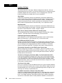
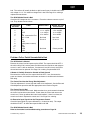
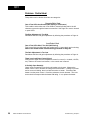
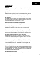
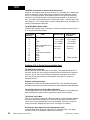
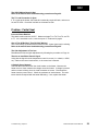
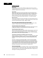
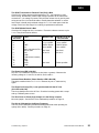
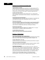
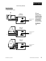
QPAC
Modular SCR
Power Control
Service Manual
Watlow Controls
1241 Bundy Blvd., P.O. Box 5580, Winona, MN 55987-5580, Phone: 507/454-5300, Fax: 507/452-4507
QPAC-SA10-9403
April, 1994
$10.00
Made in the U.S.A.
Printed on Recycled Paper
Use The Manual
How to Use the Manual
Chapter 1, Page 4
• General Description
• Indication of Malfunction
• Specifications
Chapter 2, Page 8
• Cleaning Fans, Fins,Filter
• Tightening Connections
• Periodic Test Runs
Chapter 3, Page 9
• Base & Firing Cards
• Operation Theory
Chapter 4, Page 15
• Test Procedures
Chapter 5, Page 17
• Troubleshooting
Appendix, Page 31
• Waveforms and Schematics
• Bench Testing
• SCRs
Notes
The user's manual contains informational notes to alert you to important details. When you
see a note icon, look for an explanation in the margin.
NOTE:
Details of a “Note”
appear here in the
narrow box on the
outside of each page.
!
Safety Information
This user's manual also has boldface safety information notes to protect both you and your
equipment. Please be attentive to them. Here are explanations:
!
CAUTION:
Details of a “Caution”
appear here in the
narrow box on the
outside of each page.
The Caution symbol (exclamation point) in the wide text column alerts you to a "CAUTION",
a safety or functional hazard which could affect your equipment or its performance. A full
explanation is in the narrow column on the outside of the page.
WARNING:
Details of a “Warning”
appear here in the
narrow box on the
outside of each page.
The Warning symbol (lightning bolt) in the wide text column alerts you to a "WARNING", a
safety hazard which could affect you and the equipment. A full explanation is in the narrow
column on the outside of the page.
Technical Assistance
If you encounter a problem with your Watlow control, review all of your configuration information to verify that your selections are consistent with your application... Inputs, Outputs,
Alarms, Limits, etc. If the problem persists after checking the above, you can get technical
assistance by dialing: 1-507-454-5300
An Applications Engineer will discuss your problem with you.
Please have the following information available when calling:
• Complete model number
• Bar Code Number
• All configuration information
• User's Manual
Your Feedback
Your comments or suggestions on this manual are welcome, please send them to:
Technical Writer, Watlow Controls, 1241 Bundy Blvd., Box 5580, Winona, MN 55987-5580,
Phone: 507/454-5300, Fax: 507/452-4507. The QPAC Service Manual is copyrighted by
Watlow Winona, Inc., © 1994, with all rights reserved.
blr 0693
2
WATLOW QPAC Service Manual
Contents
Contents
Table of Contents
Chapter 1
QPAC Modular SCR Power Control
Page
General Description .................................................................... 4
Overview ..................................................................................... 5
Replacement Parts ...................................................................... 5
Indication of Malfunction ............................................................. 5
QPAC Specifications ................................................................... 6
Chapter 2
Preventative Maintenance
Cleaning Cooling Fans, Fins and Filter ....................................... 8
Tightening Connections .............................................................. 8
Periodic Test Runs ...................................................................... 8
Chapter 3
Operation Theory of Base and Firing Cards
Single Phase Model - Q01 .......................................................... 9
Power Base Operation ................................................................ 9
Three Phase, Two Leg - Q32 .................................................... 10
Power Base Operation .............................................................. 10
Three Phase, Three Leg - Q33 ................................................. 11
Power Base Operation .............................................................. 11
Zero Cross Control Cards ......................................................... 13
Chapter 4
Test Procedures
Q01 and Q32 ............................................................................. 15
Q33 Zero Cross Adjustment ...................................................... 15
Bias and/or Gain Adjustments ................................................... 16
Current Limit Adjustments ......................................................... 16
Chapter 5
Troubleshooting
Indications of Malfunction .......................................................... 17
Troubleshooting Guidelines ...................................................... 17
Q01 Troubleshooting ................................................................. 18
Q32 Troubleshooting ................................................................. 21
Q33 Troubleshooting ................................................................. 24
Bench Testing ........................................................................... 27
Testing SCRs in the Unit ........................................................... 28
Installing an SCR Package ....................................................... 28
Troubleshooting the Base and Control Cards ........................... 28
Appendix
Waveforms and Schematics ..................................................... 31
Contents
WATLOW QPAC Service Manual
3
Overview
Chapter 1
QPAC Modular SCR Power Control
Figure 1 The QPAC-01
SCR Power Control
General Description
The QPAC Power Controls are a family of solid state controls used for electric
heating applications. A solid state power control provides output power that is proportional to the input command signal from a temperature control. This proportional output power helps to produce a closely controlled heater temperature, which
saves energy and prolongs heater life by holding heater elements at a nearly constant temperature.
The QPAC has a modular construction with plug-in features for flexibility. The
three modules of the QPAC are the power base, transformer, and control card.
See Figure 2. Power bases are available in 30 to 300Ω ratings in single phase,
three phase-two leg and three phase-three leg configurations. A transformer
plugged into the power base allows the QPAC to operate on any voltage from 120
to 480VAC. The plug in control card sets the QPACs firing mode. Control cards
are available in solid state contactor, burst firing (zero cross), or phase angle
modes with a wide variety of input options. This modular approach, using a standard power base with plug-in transformers and control cards, allows power control
users, distributors and OEMs to maintain minimum inventories while still providing
rapid service.
4
WATLOW QPAC Service Manual
Overview, Chapter 1
Overview
SCRs
Unit
Rating
• 30A
• 50A
• 75A
• 100A
• 150A
• 200A
• 300A
Part Numbers
QPAC-01 &
Q-PAC-32
Q-PAC-33
18-4013 (*1) 18-5179 (*1)
18-4013 (*1) 18-5179 (*1)
18-4013 (*1) 18-5179 (*1)
18-4015 (*1) 18-5179 (*1)
18-5052 (*2) (*NOTE 3)
18-5052 (*2) (*NOTE 3)
18-5052 (*2) (*NOTE 3)
Plug-in transformers (50/60 Hz)
Part Number
• 120VAC
16-0200
• 208/240VAC 16-0201
• 277
16-0202
• 380VAC
16-0208
• 415VAC
16-0207
• 480VAC
16-0203
• 600VAC
16-0209
(consult factory)
(*1) SCR Type: Module.
Torque 40"/LB
(*2) SCR Type: 3/4" Stud.
Torque 280-300"/LB.
(*3) SCR: 18-5052.
Diode 18-1044.
Power Bases
with Motherboards
• QPAC-01:
1Ø, 30 to 300A
• QPAC-32:
3Ø, 2-leg, 30 to 300A
• QPAC-33:
3Ø, 3-leg, 30 to 300A
Control Cards
Part Number
• Solid state contactor, AC input, QCA
08-5285
• Solid state contactor, DC input, QCD
08-5286
• Burst firing (zero cross) fixed time base, QBF
08-5289
• Burst firing (zero cross) variable time base, QBV 08-5342
• Phase angle control, QAF *
08-5288
• Phase angle control with current limiting, QAL * 08-5411
• Phase angle control with digital input, QAD *
08-5314
Figure 2 QPAC Modularity
Overview
* For 1Ø & 3Ø, 3-wire controls only; not for 3Ø, 2-leg controls
Q01 is a single phase power control that operates with any type of firing method
such as burst fired, phase angle, variable time base, and AC. It uses a pair of
back-to-back SCRs (“package” or individual) depending on amperage ratio.
Q32 is a 3-phase, 2-leg power control that can operate on most types of firing
methods, except phase angle, and controls two of the three legs. The QPAC-32
was designed for zero cross applications only. It uses two pairs of SCRs, individual or SCR package, depending on amperage ratio.
Q33 in a 3-phase, 3-wire hybrid (SCR and diode) power control that operates with any
type of firing method. It features a series of jumpers for fast AC input changes after
changing transformers, and a jumper for changing from burst fired to phase angle firing. It also has LEDs to indicate “Power On,” “Phase Lock Loop,” “Phase Rotation,”
and “Phase Loss.” For fast malfunction diagnostics, and for bench troubleshooting,
complete data is on the board at a series of test points. Integrated circuits are easy to
change by simply plugging and unplugging for replacement or testing.
Indications of Malfunction
1.
2.
3.
4.
5.
6.
No output under any circumstances.
Full ON output at all times and the load is uncontrollable.
Output is not proportional to the command signal (unbalanced output).
Operating erratic and inconsistent.
Half output.
One or more LEDs not lit on the Q33 base
Overview, Chapter 1
WATLOW QPAC Service Manual
5
Specifications
QPAC Specifications
Operation
• Modular control base with plug-in card and transformer
• Plug-in control cards
• Solid state contactor, AC or DC input
• Burst firing (zero cross) control, fixed or variable time base
• Phase angle control with soft start and current limiting, or digital input
• Plug-in transformers (50/60Hz)
• 120 VAC operation
• 208/240 VAC operation
• 380 VAC operation
• 415 VAC operation
• 480 VAC operation
• 600 VAC operation, consult factory
• Power bases
• Single phase (Q01), 1 pair of SCRs
• Three phase (Q32), 2 leg control, 2 pair SCRs.
Resistive load only, balanced or unbalanced, burst firing (zero cross) only
• Three phase (Q33), 3 pair hybrid SCRs/diodes
Recommended for phase angle only with balanced load.
Control Cards
• (QCA) Solid state contactor, AC Input (08-5285)
• 120 VAC @ 30mA minimum
• AC signal input sources (ie., Triacs or mechanical relay outputs with noise
suppression) require customer supplied resistors across the power control
AC command signal input terminals to prevent false firing.
• 24 VAC input, 200Ω/10 watts typical
• 120 VAC input, 1KΩ/25 watts typical
• 240VAC input, two 1KΩ/25 watts in series typical
• (QCD) Solid state contactor, DC Input (08-5286)
• ON, 4 to 10VDC; OFF, 0VDC
• Built-in noise reduction network
• (QBF) Burst firing (zero cross) control Fixed Time Base (08-5289)
• Process input factory set @ 4-20mA
• Input impedance 250Ω (clip resistor for 5KΩ voltage input)
• Time Base 4 seconds (clip resistor for 1 sec)
• (QBV) Burst firing (zero cross) control , Variable Time Base (08-5342)
• Process input factory set @ 4-20mA
• Input impedance 250Ω (clip resistor for 5KΩ voltage input)
• Bias and Gain card optional
• (QAF) Phase angle control (08-5288)
• Process input factory set @ 4-20mA
• Input impedance 250Ω (clip resistor for 5KΩ voltage input)
• Soft start 10 sec (approximately)
• (QAL) Phase angle control with current limit: (08-5411)
Some heater elements change resistance during their operation, (i.e., silicon
carbide). In order to control at a slow ramp, it is often advantageous to limit the
current. Sensing the current is via a current transformer. This is NOT a means
of protecting the SCR.
• Process input factory set @ 4-20mA
• Input impedance 250Ω (move jumper for 5KΩ voltage input)
• Soft start 10 sec (approximately)
• Current transformer included
• Current Limiting.
• (QAD) Phase angle control with digital input (08-5314)
• Remote digital phase control
• Interface, Centronics® parallel, 8 lines
• Power steps, 256
6
WATLOW QPAC Service Manual
Overview, Chapter 1
Output
• 120VAC through 480VAC (600VAC, consult factory)
• 1, 2, or 3 pole
• 30 through 300 amps per pole
Power
• Frequency 50/60 Hz
• Voltage +/- 10%, 120/208/240/277/380/415/480VAC (600VAC, consult factory)
Power Dissipation (Watts)
• 1.5 watts/amps per controlled leg
Line Voltage Compensation
• 10% ∆ in line, 2%∆ in load in the 30% to 70% power region (QAF, QAL & QBV)
Isolation
• Command signal to load 1250VAC minimum
Linearity
• 2%, 30% to 70% power region (All units except QAD, QCA & QCD)
Off State Leakage Current
• 20mA @ 480VAC
SCR Protection
• l2t fuses provided, dv/dt 200V/ µsec minimum.
I2t are fast acting fuses designed to protect SCRs and capable of opening
(blowing) inside 1/2 cycle (2.3 msec). They are not designed for protection of
other parts of the heater system and should not be used in place of circuit
breakers or fusible disconnects.
• Q33 units equipped with MOV and snubber. Q01 & Q32 units, snubber only.
• (Q32) 3rd leg fuse kit may be used, but not required, with 3 phase- 2 leg models
Cooling
• Fans provided in 75A to 100A units must be supplied with 120VAC (or 240VAC),
20 watts fan power each
• All fans wired by the customer, Q01: 75A through 300A units, 1 fan; Q32: 30A
through 100A units, 1 fan; 150A, 200A, 300A units, 2 fans; Q33: 30A through
100A units, 2 fans; 150A, 200A, 300A units, 3 fans
• Natural convection only: Q01: 30A and 50A units
Heat Sink Thermostat. SCRs that incorporate a fan for forced air cooling can
reach unsafe temperatures if the fan fails. All Loyola SCRs with fan cooling
incorporate a heat sink thermostat to remove power from the SCR in case of fan
failure, filter blockage, or excess heat in the enclosure.
Agency Approval
• UL recognition to 300 Amps, UL873, File # E43684. Listed under UL508,
File #E73741
Mounting
• Orientation: Heat sink fins must be vertical
Operating Environment
• 32 ˚F to 122 ˚F/0 ˚C to 50 ˚C
• 0 to 90% RH, non-condensing
Weight
• lbs (kg)
Phase
Amps
1ø/Q01 3ø,2 leg/Q32 3ø,3 wire/Q33
30
6 (2.7)
8 (3.6)
20 (9.1)
50
6 (2.7)
8 (3.6)
20 (9.1)
75
10 (4.5)
15 (6.8)
50 (22.7)
100
10 (4.5)
15 (6.8)
50 (22.7)
150
15 (6.8)
36 (16.3)
50 (22.7)
200
15 (6.8)
36 (16.3)
50 (22.7)
300
15 (6.8)
36 (16.3)
50 (22.7)
Specifications
Options
• Manual Control Kit (1KΩ potentiometer) #08-5362
• 240VAC fans in place of 120VAC fans
• 600VAC operation, consult factory
Overview, Chapter 1
WATLOW QPAC Service Manual
7
Procedures
Chapter 2
Preventive Maintenance
Cleaning Cooling Fans, Fins and Filter
Cooling a power control is critical to its reliable operation. Your unit should be
inspected and cleaned every six months (more frequently in dirty environments).
To achieve this, follow this simple procedure.
1. Remove power from the control. There may be more than one disconnect
since the fan power is separate from the main power.
2. Inspect and clean the cooling fans and heat sink fins. In most cases an air
hose is sufficient to remove lint or dirt which may block air flow.
3. Once again, inspect and clean any fans and/or filters which may bring air into
or out of the enclosure. If the filters are not cleanable replace them.
Tightening Connections
Loose (arcing) connections can and will destroy SCRs. Stranded wire has a tendency to "cold flow" when clamped in a screw down compression connector.
After installation and every six months:
1. Remove power from the control.
2. Inspect and tighten all connections from the circuit breaker to the heaters.
Periodic Test Runs
If the system has been idle for a period of time, it is necessary to perform regular
maintenance and periodically test the equipment. If the system has been idle for a
period of time, follow this procedure before further use.
1. Make sure the power is turned OFF.
2. Check for moisture, dirt or foreign materials in the enclosure.
3. Check all connections making sure they are tight.
Certain heater types take on moisture when not in use.
1. Disconnect the heaters from the power control.
2. Test the heaters for resistance to ground using a high-pot tester or a “megger.”
Check with the heater manufacturer for the resistance or proper high pot tester.
It may be necessary to dry the heater out before running it with the QPAC.
To test the system:
1. When calling for full heat, measure the output voltage and current for each phase.
2. Make sure the system removes all current from the load when the temperature
control is not calling for heat. (Voltage may still be measured from phase to
ground.
3. Check any safety or limit controls in the system.
8
WATLOW QPAC Service Manual
Maintenance, Chapter 2
Q01
Chapter 3
Operation Theory of
Base and Firing Cards
Single Phase Model - Q01
Figure 3 Q01 Board Layout
Power Base Operation
The Q01 uses one pair of SCRs connected in inverse parallel to control a resistive
or inductive load. The main board contains the power supply, output drivers, and
connections for the transformer, and the control card. The Q01 accepts all control
cards. The standard Q01 power base takes any transformer from 120VAC to
480VAC. 600VAC requires a special base.
The Q01 main board provides power and FWZ (full wave zero cross) to detect
zero crossover to the control board. The control board then outputs a pulse for
each half cycle to turn ON the instrument SCRs which in turn fire the power SCRs.
Two windings of the power transformer provide power for the instrument SCRs.
See schematic 02-0655 on Page 33.
Figure 4 Q01 Block Diagram
and Typical Load
Circuit
Load Circuit
Power
Supply
FWZ
L1
L1
Opto
VAC
Control Card
Opto
T1
Heater
L2
Operation Theory, Chapter 3
WATLOW QPAC Service Manual
9
Q32
Three Phase, Two Leg - Q32
Figure 5 Q32 Board Layout
Power Base Operation
The Q32 uses two pair of SCRs connected in inverse parallel to control two lines of
a three phase ungrounded, resistive load. The main board contains the power
supply, the output drivers, connections for the transformer and any of the zero
cross control cards. It is interlocked so that it will not allow any output if a phase
angle card is installed. Q32's will accept 208 to 480 volt transformers as standard.
600 volt units need to be special ordered.
The master portion of the Q32 operates the same as the Q01. Once SCR #2 fires,
transformer T2 receives load voltage and T2B then turns on SCR #4 approximately
60 degrees before zero crossing on L3 phase. As soon as L3 goes negative, SCR
#4 is ON. The next half cycle, SCR #1 is fired, and T2C turns on SCR #3. See
schematic 02-0682 on Page 34.
Figure 6 Q32 Block Diagram
and Typical Load
Circuit
Power
Supply
FWZ
L1
SCR1
L3
SCR2
Opto
VAC
L2
Control Card
Load Circuit
Opto
T1
L3
SCR3
L2
SCR4
Slave
Transformer
3Ø
Heater
T2
T3
10
WATLOW QPAC Service Manual
Operation Theory, Chapter 3
Q33
Three Phase, Three Leg - Q33
zero cross jumper
Power Base Operation
Figure 7 Q33 Board Layout
and Power Board
The Q33 uses three SCR/diode pairs
(hybrid) in inverse parallel to control a
resistive or inductive ungrounded load.
The Q33 has two boards. The main board
contains the power supply, phase locked
loop (PLL), phase counters, zero cross filter/detector, phase loss, and phase rotation circuitry. The output board contains
the SCR protection, artificial neutral, and
output drivers. The Q33 accepts 208 to
480 volt transformers as standard.
600VAC must be special ordered.
The Q33 is intended for use on phase control although it can be used on zero
cross (with some loss of output), by moving one jumper to shift the zero cross
notch.
The Q33 is much more complicated than the Q32, since it controls all three leg's
and can be used for zero cross, or phase control. U6, U3A, and U3B make up a
noise filter and the zero cross detector (FWZ). This produces a negative pulse at
each zero crossing for phase angle, and slightly after zero for zero cross firing. U1
and U2 make up a phase locked loop (PLL) which runs at 256 times the full wave
frequency. (30.72KH at 60 Hz or 25.6KH at 50Hz). This divides each half cycle
Operation Theory, Chapter 3
WATLOW QPAC Service Manual
11
Q33 Block
into 256 parts. When the control card sends out a pulse, U7A picks the correct half
cycle, and sends the pulse to U3D which starts counter #1 (U9) and counts to 1 for
a short delay. When U1 counts down, it sends a pulse to the output board to fire
SCR #1, and resets U3C, and sets U4A. See schematic 02-0798 on Page 35.
This starts counter #2 (U10) which counts to 85 (to give a 2.77ms delay). It sends
an output pulse to fire SCR #2, resets U4B, sets U4D, and starts counter #3.
Counter #3 (U11) counts to 85, sends an output pulse to fire SCR #3, (U11) counts
to 85, sends an output pulse to fire SCR #3, and resets U4C to finish the cycle.
U12 is used to detect the loss of L2 phase, (phase loss) and U13 is used to detect
the proper phase rotation. U7B, U7C, and U7D combine phase loss, phase rotation, PLL, and the thermostat for emergency shut down (ESD).
Figure 8 Q33 Block Diagram
and Typical Load
Circuit
12
WATLOW QPAC Service Manual
Operation Theory, Chapter 3
Cards
AF - Phase Angle Fired (08-5288)
The AF card provides a delayed SCR turn ON, providing an infinitely variable voltage and current from
full OFF to full ON. The AF card can be used on
resistive, inductive, or Tungsten lamp loads. It
includes a 10 second soft start, and a missing half
cycle detector to put it into emergency shut down
(ESD), and retrigger the soft start. A low signal on
the ESD terminals puts the QPAC in ESD. The
input is factory set for 4 - 20mA into 250Ω. It can be
converted to a voltage input by removing R3 and
readjusting the bias and gain potentiometers for
any voltage fan 0 - 3VDC to 0 - 15VDC.
Figure 9 QAF Board Layout
AL - Phase Angle
Fired with Current Limit (08-5411)
The AL card incorporates all of the features
of the AF card with the addition of a two
mode controller to hold the output current at
a pre-set maximum level. The load current is
monitored by a CT (current transformer) and
the maximum output can be set by a potentiometer on the card.
Figure 10 QAL Board Layout
Zero Cross Control Cards
(work on all bases)
BF - Burst Fired with
a Four Second Time Base (08-5289)
The BF card is designed for time proportioning with a 4 second
time base. It can be field changed to a 1 second time base by
removing R17. A 4 - 20mA input is standard, and can easily be
changed to accept a voltage input by removing R8 and readjusting the bias and gain pots for any voltage input from 0 3VDC to 0-15VDC. The output of the card is disabled if the
emergency shut down goes low.
Figure 11 QBF Board Layout
Operation Theory, Chapter 3
WATLOW QPAC Service Manual
13
Cards
Figure 12 QBV Board Layout
BV - Burst fired with a
Variable Time Base (08-5342)
The BV card is time proportioning with a variable (very fast) time base. At 50% power, one
full cycle is ON, and one full cycle is OFF. At
25% power, it is ON one cycle and OFF for
three. At 90%, it is ON nine cycles and OFF for
one. As the command signal gets farther from
50% power, the time base gets longer. The
maximum cycle time is 1 of 360 cycles. The BV
card is standard, setup for 4 - 20mA into 250Ω.
It can be changed to 1 - 5 VDC by removing the
resistor on the plug located on the back of the
card, adding a small circuit board (08-7210)
containing bias and gain pots allow the card to
be adjusted for any voltage from 0 - 3VDC to 0 15VDC or current between 0 and 25mA. The
card output is removed if the emergency shut
down signal is low.
CA - Contactor with an
AC Input Signal (08-5285)
The CA control card operates the same as the
CD card except it requires a 120VAC input
command signal. The CA can be special
ordered for 24VAC or 240VAC if required. The
QPAC can be kept OFF if the emergency shut
down signal is held low.
Figure 13 QCA Board Layout
CD - Contactor with a
DC Input Signal (08-5286)
The CD control card operates the QPAC power
control as a zero cross solid state contactor. A
3 - 30VDC input signal is required to switch ON
the QPAC and a 0 - 1VDC is required to switch
it OFF. The QPAC can be kept OFF if the
emergency shut down signal is held low.
Figure 14 QCD Board Layout
14
WATLOW QPAC Service Manual
Operation Theory, Chapter 3
Procedures
Chapter 4
Test Procedures
Q01 and Q32
No power base adjustments are required on the Q01 and Q32 models. See the
bias and gain control card procedures.
Q33 Zero Cross Adjustment
Follow this step by step procedure to test the Q33 zero cross adjustment.
Equipment Needed:
• Dual trace oscilloscope
2V/Div
Procedure:
1. Set Channel A on the scope to 5 volts per division.
2. Set Channel B to 2 volts per division.
3. Center both channels vertically.
4. Place the zero cross jumper in the phase angle position. See Page 11 for
the board layout.
5. Unplug the control card.
6. Connect the scope common to test point COM on the mother board (next to
the control card plug).
7. Connect the Channel A probe to Test Point 1 (TP1), located on the upper
right corner of the mother board. The card is unplugged.
8. Connect the Channel B probe to Test Point 6 (TP6) FWZ.
9. Turn power ON.
10. Adjust potentiometer P1 until the FWZ notch (Channel B) is centered on the
sine wave (Channel A). Refer to the scope picture below.
5V/Div
Figure 15 Q33 Scope Output
2ms/Div
Test Procedures, Chapter 4
WATLOW QPAC Service Manual
15
Bias & Gain
❋ NOTE:
Any adjustments or
troubleshooting of
this unit should be
done by a qualified
technician.
These adjustments are necessary for the following control cards:
QBF - Bias and Gain adjustments
QBV - Gain adjustment
QAL - Bias, Gain and Current Limit adjustments
QAF - Bias and Gain adjustments
Bias and/or Gain Adjustments
The bias and gain are factory set for a command signal of 4 - 20mA. However, if
minor or major adjustments are required, follow this adjustment procedure.
1. Set the temperature control for zero output (4mA or 0VDC) by adjusting the set point
below the ambient temperature, or put the control in manual mode at 0% power.
a. If there is an output, turn the bias potentiometer clockwise until the
output just disappears.
b. If there is no output, turn the bias potentiometer counterclockwise until
the output is noted, then turn it back to until it is just OFF.
2. Set the temperature control for full output (20mA or 5VDC) by turning the set point
above the ambient temperature, or put the control in manual mode at 100% power.
a. If the output of the SCR is full ON, turn the gain potentiometer counter
clockwise until a drop in the output is noted. Next, turn the pot back to
until the output is just full ON.
b. If there is no SCR output, or the output is not full ON, turn the gain
potentiometer pot clockwise until the output is just full ON.
3. Repeat Steps 1 and 2 until no further adjustments are necessary.
Current Limit Adjustments
The QAL control card is a phase angle control with the capability to limit the maximum current to the load. A potentiometer on the QAL card adjusts the current limit
setting. Use the following procedure to adjust the current limit on initial setup. The
purpose of the procedure is to bring the load power up slowly so the maximum current to the load is not exceeded before the current limit is adjusted.
❋Note: If the input signal from the temperature control is abruptly increased,
a short overcurrent through the load may occur as the QAL card circuitry detects the
higher current.
1. Attach a clamp-on ammeter to the load line.
2. Adjust the QAL card current limit potentiometer fully counterclockwise (for minimum current flow).
3. Turn the temperature control ON, and adjust the input signal to the control card
for 0% power.
4. Turn the power to the QPAC ON.
5. Gradually increase the input signal.
6. Adjust the current limit potentiometer clockwise until current to the load is measurable.
7. Gradually increase the input signal to 100% power, then adjust the current limit
potentiometer to obtain the desired maximum current to the load.
16
WATLOW QPAC Service Manual
Test Procedures, Chapter 4
Procedures
Chapter 5
Troubleshooting
Indications of Malfunction
1.
2.
3.
4.
5.
6.
No output under any circumstances.
Full ON output at all times and the load is uncontrollable.
Output is not proportional to the command signal (unbalanced output).
Operating erratic and inconsistent.
Half output.
One or more LEDs not lit on the Q33 base
Troubleshooting Guidelines
Troubleshooting the QPAC should be limited to changing fuses, transformers, SCRs
and printed circuit boards. Any other troubleshooting should be done on a test bench
and by a qualified electronic technician capable of working on high voltage.
WARNING:
When working on a power control, caution must be used as high voltage is
present when power is applied.
On power bases of 100 amps or less, the heat sinks should be at ground
potential. Units above 100 amps are electrically hot.
Before troubleshooting, make sure you have isolated the problem to the QPAC.
Make sure all connectors and load terminations are tight and the control card is
seated properly. Next, verify that there is AC power present at L1 and L2. For
three phase units check at L3 by measuring phase to phase. Phase to ground is
meaningless on ungrounded three-phase loads. Verify that there is a good command signal (i.e. 4-20mA) from the temperature control, and that the temperature
control is operating properly.
Troubleshooting the QPAC can be narrowed down to three distinct problems.
• Unit has no heat
• Unit has partial heat
• Full or partial uncontrollable heat
Once you have determined the category that best describes your situation, read
through the appropriate section on the following pages. Follow the procedure
which applies to you.
Troubleshooting, Chapter 5
WATLOW QPAC Service Manual
17
Q01
Problem: No Heat
Blown Fuse
This can be done one of two ways. Measure voltage across the fuse. If there is
voltage present the fuse is bad. You can also check the fuse for continuity using an
ohmmeter. Replace the fuse if necessary. Prior to changing fuses, check the
heaters and wiring for a possible short or loose connections.
Open Heater
Check all the connections from the circuit breaker to the heaters. Measure the
heater current. Next, measure the voltage across the heater. If voltage is present
and no current is flowing, there is a bad connection or heater. Disconnect the
heater from the power control. Check the resistance of each element. The resistance should correspond with the heater KW rating. If not, replace the heater.
Bad Connection
Check all the connections from the circuit breaker to the heaters. Measure the current and output voltage from the heater. If voltage is present and no current is flowing, there is a bad connection or heater. Repair or replace.
Open Limit or Safety Contactor Within the Thermal System
The overtemperature limit contactor may have tripped. Check the limit or safety
contactor. Locate the cause for the limit tripping, correct and reset.
Command Signal Polarity is Backwards
Verify that the mA or VDC signal from the temperature control is wired correctly.
Make sure Terminal 5 is (-) and Terminal 4 is (+) on the control card.
The SCR Switch Will Not Turn ON
With the command signal full ON (20mA for a 4-20mA signal), check the VAC voltage drop across the L1 and T1 terminals. They should read approximately 1.5VAC. If
you are reading the line voltage potential, the SCR is not turning on. The mother
board or control card may be bad. Try another control card or contact the factory.
The Interlock Connection on the QPAC Control Card is Open
Measure voltage from Terminal 5 (-) to Terminal 1, then from Terminal 5 to 2 on
the control card. Voltage must be present at both Terminal 1 and 2. If not, place a
jumper between these terminals. If you are using the interlock feature, check the
interrupt switch or the interlock.
The Unit is in Emergency Shut Down (ESD) - For Fan-Cooled Units ONLY
If the heat sink temperature exceeded 187°F (86°C) the on-board thermostat will
close and the QPAC will enter Emergency Shut Down. More than likely a clogged
or non-operational fan is the cause. Check the fan and clean if necessary. If the
problem still exists, check for a shorted heat sink thermostat, unclog the fan, check
for fan power or replace the fan.
The Control Card is Bad
First, try to re-seat the control card. Make sure there is a good connection between
the control card and the mother board. If there is still a problem, replace the control
card with another card. Also, check the troubleshooting section on Page 29 or 30.
See Page 5 for ordering a replacement card.
The QPAC Transformer or Resistor Fuse (R10) is Bad
Check for AC voltage present at the transformer (T1), see Page 33 for transformer
wiring. Be extremely careful! High voltage is present on the transformer connections. If no voltage is present, verify that the resistor fuse is good by measuring
across R10. You should be able to visually determine whether or not the fuse is
18
WATLOW QPAC Service Manual
Troubleshooting, Chapter 5
Q01
bad. The resistor will usually be black or dark brown if open. It should read a minimal voltage of < 1V. If it reads line voltage R10 is bad. See Page 5 for ordering a
replacement transformer.
The QPAC Mother Board is Bad
Check the DC voltages at the J1 connector. Place the voltmeter common on pin 7
or 8. They should read as follows:
J1 Connector
Test Point
1
2
3
4
5
Label
T STAT
-V
FWZ*
+V
Q32, connected to Pin 1
Q01 or Q33
6
+5V
7
COM
8
COM (meter common)
9
KEY
10
COM
11
+LED
12
COM
*See scope pictures on Page 31.
Without Card
Not Used
-11 to -14VDC
11 to 14VDC
15 to 18VDC
With BF, AF or AL
Card Installed
3 to 5V
-15 to -22VDC
11 to 14VDC*
15 to 18VDC
Not Used
5V ±0.1V
Not Used
5V ±0.1V
Not Used
Pulses possible
Problem: Full or Partial Uncontrollable Heat
The SCR Switch is Shorted
Remove the control card and power up the QPAC. The output should be OFF. If
the unit is still full ON, remove power and disconnect the load wires and measure
across L1 and T1 with an ohmmeter. If resistance is low (5Ω or less), the SCR is
shorted and must be replaced. See Page 5 for ordering a replacement SCR.
A Heater is Partially Shorted or Shorted to Earth Ground
Disconnect the control card; the output should be OFF. If not, disconnect the
power and heater, and measure the heater resistance. It should match the heater
KW rating.
The Control Card has the Wrong Bias Adjustment
The bias adjustment is set too high and needs to be readjusted. See the Bias and
Gain Adjustment procedure with the appropriate control card on Page16.
The Control Card is Bad
First, try to re-seat the control card. Make sure there is a good connection between
the control card and the mother board. Power down the control and remove the
control card. Power up without the control card installed. If there is no heat, the
control card is bad. Replace the control card. See Page 5 for ordering.
An Excessive Input Signal from the Temperature Control
Check the input signal for proper calibration (i.e. 4-20mA at 4mA). The output
should be full OFF. At 20mA the output should be full ON.
The QPAC Mother Board is Bad
Refer to the mother board troubleshooting procedure on Page 28.
Troubleshooting, Chapter 5
WATLOW QPAC Service Manual
19
Q01
Problem: Partial Heat
This problem can be broken down into two categories:
Uncontrollable Heat
One of Two SCRs has Shorted (Half Waving is Continuous)
This condition exists when one of two SCRs is shorted, allowing half of the AC
sinewave to pass through the heater uncontrolled. See Page 19 to test for shorted
or open SCRs.
The Bias Adjustment is Too High
Recalibrate the bias and gain adjustments by following the procedure on Page 16.
Insufficient Heat
One of Two SCRs Won’t Turn ON (Half Waving)
This is most likely a problem with the mother board. A gate signal may be missing.
Refer to the mother board troubleshooting procedure on Page 28.
The Gain Adjustment is Too Low
Recalibrate the bias and gain adjustments by following the procedure on Page 16.
There is an Insufficient Control Signal
Verify that the signal from the temperature control is correct (i.e. 4-20mA, 1-5VDC,
etc.) Refer to the control card section, or the control user’s manual.
A Partially Open Heater(s)
Check all the connections from the circuit breaker to the heater. Measure the
heater current. Next, measure the voltage across the heater. If voltage is present
and no current is flowing, there is a bad connection or heater. Disconnect the
heater from the power control. Check the resistance of each element. The resistance should correspond with the heater KW rating. If not, replace the heater.
20
WATLOW QPAC Service Manual
Troubleshooting, Chapter 5
Q32
Problem: No Heat
Blown Fuse
This can be done one of two ways. Measure voltage across the fuse. If there is
voltage present the fuse is bad. You can also check the fuse for continuity using an
ohmmeter. Replace the fuse if necessary.
Open Heater
Check all the connections from the circuit breaker to the heaters. Measure the
heater current. Next, measure the voltage across the heater. If voltage is present
and no current is flowing, there is a bad connection or heater. Disconnect the
heater from the power control. Check the resistance of each element. The resistance should correspond with the heater KW rating. If not, replace the heater.
Bad Connection
Check all the connections from the circuit breaker to the heaters. Measure the current and output voltage from the heater. If voltage is present and no current is flowing, there is a bad connection or heater. Repair or replace.
Open Limit or Safety Contactor Within the Thermal System
The overtemperature limit contactor may have tripped. Check the limit or safety
contactor. Locate the cause for the limit tripping, correct and reset.
Command Signal Polarity is Backwards
Verify that the mA or VDC control signal from the temperature control is wired correctly. Make sure Terminal 5 is (-) and Terminal 4 is (+) on the control card.
The SCR Switch Will Not Turn ON
With the command signal full ON, check the VAC voltage across the L1 and T1 terminals, and the L3 and T3 terminals. They should read approximately 1.5VAC. If
you are reading the line voltage potential, the SCR is not gating on. The mother
board or control card may be bad. Try another control card or contact the factory.
The Interlock Connection on the QPAC Control Card is Open
Measure voltage from Terminal 5 (-) to Terminal 1, then from Terminal 5 to 2 on
the control card. Voltage must be present at both Terminal 1 and 2. If not, place a
jumper between these terminals. If you are using the interlock feature, check the
interrupt switch or the interlock.
The Unit is in Emergency Shut Down (ESD) - For Fan-Cooled Units ONLY
If the heat sink temperature exceeded 187°F (86°C) the on-board thermostat will
close and the QPAC will enter Emergency Shut Down. More than likely a clogged
or non-operational fan is the cause. Check the fan and clean if necessary. If the
problem still exists, check for a shorted heat sink thermostat, unclog the fan, check
for fan power or replace the fan.
The Control Card is Bad
First, try to re-seat the control card. Make sure there is a good connection between
the control card and the mother board. If there is still a problem, replace the control
card with another card. Also, check the troubleshooting section on Page 29 or 30.
See Page 5 for ordering a replacement card.
The Phase Angle Card is Installed
The QPAC-32 is interlocked, and cannot operate with a phase control card.
Troubleshooting, Chapter 5
WATLOW QPAC Service Manual
21
Q32
The QPAC Transformer or Resistor Fuse (R10) is Bad
Check for AC voltage present at the transformer (T1), see Page 34 for transformer
wiring. Be extremely careful! High voltage is present on the transformer connections. If no voltage is present, verify that the resistor fuse is good by measuring
across R10. You should be able to visually determine whether or not the fuse is
bad. The resistor will usually be black or dark brown if open. It should read a minimal voltage of < 1V. If it reads open circuit line voltage, R10 is bad. See Page 5 for
ordering a replacement transformer.
The QPAC Mother Board is Bad
Check the DC voltages at the J1 connector. Place the voltmeter common on pin 7
or 8. They should read as follows:
J1 Connector
Test Point
1
2
3
4
5
Label
T STAT
-V
FWZ*
+V
Q32, connected to Pin 1
Q01 or Q33
6
+5V
7
COM
8
COM (meter common)
9
KEY
10
COM
11
+LED
12
COM
*See scope pictures on Page 31.
Without Card
Not Used
-11 to -14VDC
11 to 14VDC
15 to 18VDC
With BF Card
Installed
3 to 5V
-15 to -22VDC
11 to 14VDC*
15 to 18VDC
Not Used
5V ±0.1V
Not Used
5V ±0.1V
Not Used
Pulses possible
Problem: Full or Partial Uncontrollable Heat
The SCR Switch is Shorted
Remove the control card and power up the QPAC. The output should be OFF. If
the unit is still full ON, remove power and disconnect the load wires and measure
across L1 and T1, and L3 and T3 with an ohmmeter. If resistance is low (5Ω or
less), the SCR is shorted and must be replaced. See Page 5 for ordering a
replacement SCR.
A Heater is Partially Shorted
Disconnect the control card; the output should be OFF. If not, disconnect the power
and heater, and measure the heater resistance. It should match the heater KW rating.
The Control Card has the Wrong Bias Adjustment
The bias adjustment is set too low and needs to be readjusted. See the Bias and
Gain Adjustment procedure with the appropriate control card on Page18.
The Control Card is Bad
First, try to re-seat the control card. Make sure there is a good connection between
the control card and the mother board. Power down the control and remove the
control card. Power up without the control card installed. If there is no heat, the
control card is bad. Replace the control card. See Page 5 for ordering.
An Excessive Input Signal from the Temperature Control
Check the input signal for proper calibration (i.e. 4-20mA at 4mA). The output
should be full OFF. At 20mA the output should be full ON.
22
WATLOW QPAC Service Manual
Troubleshooting, Chapter 5
Q32
The QPAC Mother Board is Bad
Refer to the mother board troubleshooting procedure on Page 28.
The T1 Load Connection is Open
If T1 is open at the heater, the leads will occasionally couple AC back, and turn on
L3 and T3 SCRs. Check the load with an ohmmeter at Q32.
Problem: Partial Heat
Incorrect Phase Rotation
The phase rotation must be “A-B-C”. Measure voltage T1 to T2, T2 to T3, and T3
to T1. If it is not within 2 to 5%, reverse any two “L” leads and try again.
One of Two SCRs Won’t Turn ON (Half Waving)
This is most likely a problem with the mother board. A gate signal may be missing.
Refer to the mother board troubleshooting procedure on Page 28.
The Gain Adjustment is Too Low
Recalibrate the bias and gain adjustments by following the procedure on Page 16.
There is an Insufficient Control Signal
Verify that the signal from the temperature control is correct (i.e. 4-20mA, 1-5VDC,
etc.) Refer to the control card section, or the control user’s manual.
A Partially Open Heater(s)
Check all the connections from the circuit breaker to the heater. Measure the
heater current. Next, measure the voltage across the heater. If voltage is present
and no current is flowing, there is a bad connection or heater. Disconnect the
heater from the power control. Check the resistance of each element. The resistance should correspond with the heater KW rating. If not, replace the heater.
Troubleshooting, Chapter 5
WATLOW QPAC Service Manual
23
Q33
Problem: No Heat
Blown Fuse
This can be done one of two ways. Measure voltage across the fuse. If there is
voltage present the fuse is bad. You can also check the fuse for continuity using an
ohmmeter. Replace the fuse if necessary.
Open Heater
Check all the connections from the circuit breaker to the heaters. Measure the
heater current. Next, measure the voltage across the heater. If voltage is present
and no current is flowing, there is a bad connection or heater. Disconnect the
heater from the power control. Check the resistance of each element. The resistance should correspond with the heater KW rating. If not, replace the heater.
Bad Connection
Check all the connections from the circuit breaker to the heaters. Measure the current and output voltage from the heater. If voltage is present and no current is flowing, there is a bad connection or heater. Repair or replace.
Open Limit or Safety Contactor Within the Thermal System
The overtemperature limit contactor may have tripped. Check the limit or safety
contactor. Locate the cause for the limit tripping, correct and reset.
Command Signal Polarity is Backwards
Verify that the 4-20mA control signal from the temperature control is wired correctly. Make sure Terminal 5 is (-) and Terminal 4 is (+) on the control card.
The SCR Switch Will Not Turn ON
With the command signal full ON, check the VAC voltage across the L1 and T1 terminals. They should read approximately 1.5VAC. If you are reading the line voltage potential, the SCR is not gating on. The mother board or control card may be
bad. Try another control card or contact the factory.
The Interlock Connection on the QPAC Control Card is Open
Measure voltage from Terminal 5 (-) to Terminal 1 or 2 on the control card. Voltage
must be present at both Terminal 1 and 2. If not, place a jumper between these
terminals. If you are using the interlock feature, check the interrupt switch or the
interlock.
The Unit is in Emergency Shut Down (ESD) - For Fan-Cooled Units ONLY
If the heat sink temperature exceeded 187°F (86°C) the on-board thermostat will
close and the QPAC will enter Emergency Shut Down. More than likely a clogged
or non-operational fan is the cause. Check the fan and clean if necessary. If the
problem still exists, check for a shorted heat sink thermostat. Measure from the
thermostat, unclog the fan, check for fan power, or replace the fan.
The Control Card is Bad
First, try to re-seat the control card. Make sure there is a good connection between
the control card and the mother board. If there is still a problem, replace the control
card with another card. Also, check the troubleshooting section on Page 29 or 30.
See Page 5 for ordering a replacement card.
24
WATLOW QPAC Service Manual
Troubleshooting, Chapter 5
Q33
The QPAC Transformer or Resistor Fuse (R10) is Bad
Check for AC voltage present at the transformer (T1), see Page 35 for transformer wiring. Be extremely careful! High voltage is present on the transformer
connections. If no voltage is present, verify that the resistor fuse is good by measuring across R10. You should be able to visually determine whether or not the
fuse is bad. It should read a minimal voltage of < 1V. If it reads open circuit line
voltage, R10 is bad. See Page 5 for ordering a replacement transformer.
The QPAC Mother Board is Bad
Check the DC voltages at the J1 connector. Place the voltmeter common on pin
7 or 8. They should read as follows:
J1 Connector
Test Point
1
2
3
4
5
Label
Without Card
T STAT
-V
FWZ*
+V
Q32, connected to Pin 1
Q01 or Q33
6
+5V
7
COM
8
COM (meter common)
9
KEY
10
COM
11
+LED
12
COM
*See scope picture on Page 15.
Not Used
-11 to -14VDC
+5VDC Pulses
15 to 18VDC
With BF, AF or AL
Card Installed
3 to 5V
-15 to -22VDC
+5VDC Pulses*
15 to 18VDC
Not Used
5V ±0.1V
Not Used
5V ±0.1V
Not Used
Pulses possible
The Phase Loss LED is Not ON
Any one or a combination of phases are low (20% or greater). Measure the
incoming voltage on L1 and L2, L2 and L3, and L3 and L1.
Incorrect Phase Rotation (Phase Rotation LED is Not ON)
The phase rotation must be L1 - L2 - L3. Reverse any two “L” leads and try
again.
The Phase Lock Loop (PLL) is not synchronized with the AC Line
(PLL LED is Not ON)
There is probably noise on the AC line. Check the incoming power with a scope
and try a different power source.
The Zero Cross or Phase Angle Jumper is in the Wrong Location
Move the jumper. See the Zero Cross Calibration procedure on Page 15.
The Unit is Calibrated for the Wrong Frequency
The Zero Cross Calibration procedure must be performed at the operating frequency (50 or 60Hz). See this procedure on Page 15.
Troubleshooting, Chapter 5
WATLOW QPAC Service Manual
25
Q33
Problem: Full or Partial Uncontrollable Heat
The SCR Switch is Shorted
Remove the control card and power up the QPAC. The output should be OFF. If
the unit is still full ON, remove power and disconnect the load wires and measure
across L1 and T1 with an ohmmeter. If resistance is low (5Ω or less), the SCR is
shorted and must be replaced. See Page 5 for ordering a replacement SCR.
A Heater is Partially Shorted
Disconnect the control card; the output should be OFF. If not, disconnect the
power and heater, and measure the heater resistance. It should match the heater
KW rating.
Card has the Wrong Bias Adjustment
The bias adjustment is set too low and needs to be readjusted. See the Bias and
Gain Adjustment procedure with the appropriate control card on Page16.
The Control Card is Bad
First, try to re-seat the control card. Make sure there is a good connection between
the control card and the mother board. Power down the control and remove the
control card. Power up without the control card installed. If there is no heat, the
control card is bad. Replace the control card. See Page 5 for ordering.
An Excessive Input Signal
Check the input signal for proper calibration (i.e. 4-20mA at 4mA). The output
should be full OFF. At 20mA the output should be full ON.
The QPAC Mother Board is Bad
Refer the the mother board troubleshooting procedure.
Problem: Partial Heat
One of Three SCRs Won’t Turn ON (Half Waving)
This is most likely a problem with the mother board. A gate signal may be missing.
Refer to the mother board troubleshooting procedure on Page 28 - 29.
The Gain Adjustment is Too Low
Recalibrate the bias and gain adjustments by following the procedure on Page 16.
There is an Insufficient Control Signal
Verify that the signal from the temperature control is correct (i.e. 4-20mA, 1-5VDC,
etc.) Refer to the control card section, or the control user’s manual.
A Partially Open Heater(s)
Check all the connections from the circuit breaker to the heater. Measure the
heater current. Next, measure the voltage across the heater. If voltage is present
and no current is flowing, there is a bad connection or heater. Disconnect the
heater from the power control. Check the resistance of each element. The resistance should correspond with the heater KW rating. If not, replace the heater.
The Zero Cross or Phase Angle Jumper is in the Wrong Location
Move the jumper. See the Zero Cross Calibration procedure on Page 15.
26
WATLOW QPAC Service Manual
Troubleshooting, Chapter 5
Bench Testing
Bench Testing Hookups
Equipment Required
• Dummy Load, min. 1A
• 0-15VDC Command (signal)
❋
❋ NOTE:
QPAC-01
Single Phase
Load
or
T2
T1
L2
L1
AC
T1
Command Signa
4-20mA or
0-5VDC
+-
Dummy loads can
be made up using
100 watt light bulbs.
Bulbs can be put in
series to obtain the
proper voltage rating. (4each, 100
watt, 120V bulbs
per phase for 480V)
Control Card
An SCR will not
latch without a
load.
QPAC-32
3 Phase
Load
T3
T2
T1
L3
L2
L1
AC
T1
Command Signa
4-20mA or
0-5VDC
+Control Card
QPAC-33
3 Phase
Load
AC
Troubleshooting, Chapter 5
T3
L3
T2
L2
T1
L1
T1
Command Signa
4-20mA or
0-5VDC
+Control Card
WATLOW QPAC Service Manual
27
SCRs
Testing SCRs in the Unit
A shorted SCR will show full uncontrollable line voltage at the T terminals. To test,
turn main power OFF, remove the L and T wires. On a QPAC-01, measure resistance from L1 to T1. On a QPAC-32, measure resistance between L1 to T1 and
L3 to T3. On a QPAC-33, measure resistance between L1 to T1, L2 to T2, and L3
to T3. A reading of 5 ohms resistance or less indicates that the SCR is shorted. A
high resistance reading indicates that the SCR is good.
On a Q33 unit, a low reading will occur in one direction and a high reading in the
other direction. This is normal.
Installing an SCR Package
After removing the old SCR package, thoroughly clean the heat sink and the base
of the new SCR package to be installed. Add a thin coat of DOW-DC-4 thermal
joint compound, or equivalent, to the base of the heat sink or bottom of SCR package. Put in screws and tighten. See Chapter 1, page 5, for replacement parts and
torque settings.
Troubleshooting the Base and Control Cards
QPAC-01
The QPAC-01 main board provides power and FWZ (to detect zero crossover) to
the control board. The control board then outputs a pulse for each half cycle to
turn ON the instrument SCRs which in turn fire the power SCRs. Two windings of
the power transformer provide power for the instrument SCRs. See schematic 020655 on Page 33.
QPAC-32
The master portion of the QPAC-32 operates the same as the QPAC-01. Once
SCR #2 fires, transformer T2 receives load voltage and T2B then turns on SCR #4
approximately 60° before zero crossing on the L3 phase. As soon as L3 goes negative, SCR #4 is ON. The next half cycle, SCR #1 is fired, and T2C turns on SCR
#3. Pin 5 on the Q32 base is connected to Pin 1. All phase angle cards have Pin
5 grounded, therefore if a phase angle card is used on a Q32 base, it will stay in
permanent emergency shut down. See schematic 02-0682 on Page 34.
QPAC-33
The QPAC-33 is a lot more complicated since it controls all three legs and can be
used for zero cross, or phase control. U6, U3A, and U3B make up a noise filter
and the zero cross detector (FWZ). This produces a negative going pulse at each
zero crossing for phase angle, and slightly after zero for zero cross firing. U1 and
U2 make up a phase locked loop (PLL) which runs at 256 times the full wave frequency (30.72KH at 60 Hz or 25.6KH at 50 Hz). This divides each half cycle into
256 parts. When the control card sends out a pulse, U7A picks the correct half
cycle, and sends the pulse to U3D which starts counter #1 (U9) and counts to one
for a short delay. When U1 counts down, it sends a pulse to the output board to
fire SCR 1, and resets U3C, and sets U4A. This starts counter #2 (U10) which
counts to 85 (to give a 2.77 millisecond delay), and sends an output pulse to fire
SCR #2, resets U4B, sets U4D, and starts counter #3. Counter #3 U11) counts to
85, sends an output pulse to fire SCR #3, and resets U4C to finish the cycle.
28
WATLOW QPAC Service Manual
Troubleshooting, Chapter 5
Cards
U12 is used to detect the loss of L2 phase, (phase loss) and U13 is used to detect
the proper phase rotation. U7B, U7C, and U7D combined phase loss, phase rotation, PLL, and the thermostat for ESD.
Scope picture 2 shows the AC input (L1 to L3) at TP1 and TP6 (FWZ) after zero
cross calibration. Scope picture 3 is the high frequency clock TP9 (MCK). Scope
picture 4 shows the sequence of operation at approximately 50% power. From top
to bottom:
1. FWZ (zero cross reference)
2. Timing output A phase (U8, Pin 12)
3. Timing output B phase (U8, Pin 8)
4. Timing output C phase (U5, Pin 8)
5. Load Current T1
6. Load current T2
7. Load current T3
The output board contains the SCR protection, the output drivers, and power resistors to form the artificial neutral. See schematic 02-0798 on Page 35.
QCD and CA Cards (08-5286 and 08-5285)
FWZ at Pin 3 is shaped by Q1 to form a window around the zero cross point. See
Scope Picture 5. This is summed with the command signal by U1A and with the
ESD line by U1B to provide a high output at Pin 11 if the input signal is high, the
ESD signal is high, and it is at zero cross. The CA card accepts an AC signal and
U2 gives a high for each half cycle. See schematic 02-0672 (QCD) and 02-0673
(QCA) on Page 36 - 37.
QBF Card (08-5289)
Q1 and U2B make up the zero cross notch providing that the ESD signal is high.
Q2, and Q3 make up a linear ramp with a 4 second time base and approximately 2
volts high U1C is the input amplifier with the Bias and Gain amplifiers, and U1D is
used as a comparator to give a high output any time the ramp exceeds the input
signal. U2A adds the output of the comparator and the FWZ signal to give output
pulses only during the zero cross notch. See scope picture 5 (TP1, FWZ), scope
picture 6 (TP2 & 3, ramp top and comparator output bottom, scope picture 7, (TP2
& 4 ramp top and output pulses bottom). See schematic 02-0657 on Page 38.
QBV Card (08-5342)
U2A is used to make up the FWZ signal. U1A is a flip-flop clocked by the FWZ to
provide a square wave of one full cycle duration. U2B provides a delayed pulse,
slightly after the end of each full cycle. The input signal, goes into Q2 (emitter follower) which produces a collector current proportional to the voltage across the
emitter resistor. Q1 is used as a zener to linearize the output. Q3 is an emitter follower used to discharge C5 every other half cycle (Q5 prevents C5 from being discharged when ON). Once C5 voltage reaches the program point of Q4 (R14, R16)
it charges C5 through R19 and sets U1B. Since C5 can only reach its peak when
Q5 is OFF, (TP2 low) U1B will always stay on for one full cycle. With U1B output
high, U2D will allow two output pulses insuring one full cycle output minimum. If
ESD is low, U2D is inhibited from allowing FWZ pulses. See Scope Picture 8 for
TP1 & TP2 FWZ top and TP2 bottom, Scope Picture 9 for TP1 FWZ top and count
clear bottom, Scope Picture 10 for TP1 & TP4 FWZ top and output on the bottom,
Scope Picture 11 for TP1, 2, 4, 5 showing FWZ, SQ wave, output and the staircase waveform on C5. See schematic 02-0729 on Page 39.
Troubleshooting, Chapter 5
WATLOW QPAC Service Manual
29
Cards
QAF Card (08-5288)
Q1 makes up the FWZ signal which is inverted by U3A to give a high signal for all
of the half cycle but the zero cross notch. U3B, CR1, R19, and C5 detect missing
half cycles which then pulls C7 low with CR2. When C7 is low, the AF card is in
ESD. Q4 and Q3 make a linear ramp which is reset at the end of each half cycle
by the output of U3A. U1C accepts the input signal and performs the bias and
gain function. U1B adds the soft start from C9/R40, and U1D adds the line voltage
compensation. The output of U1D is then compared to the ramp by U1A to output
a square wave from U2B, providing ESD is high and it is during the high output
period of U3A. See Scope picture 12 (TP1 top inverted FWZ, TP2 ramp, TP3
comparator output, and the load current waveform (measured by a CT), scope picture 13 (TP4 top ESD, TP5 soft start dump, and Tp6 bottom soft start ramp). See
schematic 02-0656 on Page 40.
QAL Card (08-5411)
Q4 makes up the FWZ signal which is inverted by U3A to give a high signal for all
of the half cycle but the zero cross notch. U3B, CR5, R33, and C12 detect missing half cycles which then pulls C13 low with CR2. When C13 is low, the AF card
is in ESD. Q4 and Q3 make a linear ramp which is reset at the end of each half
cycle by the output of U3A. U1A accepts the input signal and performs the bias
and gain function. U1B adds the soft start from C4/R15, and U2B adds the signal
from the current limit circuit. U2C adds the line voltage compensation the output
of U2C is then compared to the ramp by U2D to output a square wave from U4C,
providing ESD is high and it is during the high output period of U3A. A current
transformer is used to monitor the output of the power control and provides an AC
signal to TB3. Its input is then converted to a DC signal by U5 which provides a
DC output equivalent to the true RMS value at the CT. U1D provides a gain of 4,
and U2C is a two mode amplifier providing both proportional and integral feedback
(for limiting the current) into U2B. U2A is a comparator to turn on the LED when in
limit. See scope picture 12 (TP1 top inverted FWZ, TP2 ramp, TP3 comparator
output, and the load current waveform, measured by a CT), scope picture 13 (TP4
top ESD, TP5 soft start dump, and TP6 bottom soft start ramp.) See schematic
02-0701 on Page 41.
QAD Card (08-5314)
U4 and U5 make up a phase locked loop (PLL) which is synchronized to the 50 or
60 Hz line. It produces an output 256 times the full wave frequency (120 X 256 =
30.72KHz) for the U5 and (100 x 256 = 25.6KHz) at 50 Hz. The input lines D0 to
D7 are used to set the power level desired. When the input lines are programmed
to give an output level, the address line is low (Pin 1), and the strobe line is pulsed
low, the octal D latch (U1) will be updated. The output of the latch goes through
the prom (U2) for inversion and to linearize the output curve. the output of the
prom is then used to program U3 which counts down from zero cross to whatever
power level is set in. See Scope Picture 14 (TP1 FWZ, TP2 +ZX180, and TP3
-ZX180. Scope 15 (TP2, TP3, and TP5 output. Picture 3 TP4 MCK (high frequency clock). See schematic 02-0671 on Page 42.
30
WATLOW QPAC Service Manual
Troubleshooting, Chapter 5
Appendix
Scope Picture 1
Figure 20
Scope Picture 5
5V/Div
2V/div
Figure 16
2ms/div
FWZ QPAC-01 and QPAC-32 Base
Figure 21
Scope Picture 6
Scope Picture 2
5V/Div
2V/div
2V/Div
Figure 17
2ms/div
FWZ CA or CD Card (U1-3), QBF Card (TP1)
15ms/div
1) (top) Ramp QBF (TP2) 2) Comparator Out QBF (TP3)
Figure 22
Scope Picture 7
Scope Picture 3
2V/div
Figure 18
2V/div
2ms/div
FWZ (top) Ref Sine Wave for QPAC-33 Base
5us/div
MCK (TP 9) QPAC-33 Base , QAD Card (TP 4)
Figure 23
200ms/div
2) Gating Output (TP4)
Scope Picture 8
Scope Picture 4
5V/div
2V/div
Figure 19
QBF
1) Ramp (TP2)
QBV
5ms/div
1) FWZ (TP1 and TP2)
2) Ref. Sine Wave (TP 2)
1) (top) FWZ (TP6)
2) T-On A (U8-12)
3) T-On B (U8-8)
2ms/div
4) T-On C (U5-8)
5) Load On (T1)
6) Load On (T2)
7) Load On (T3)
QBV
1) FWZ (TP1)
Waveforms, Appendix
Scope Picture 9
2V/div
Figure 24
5ms/div
2) Count Clear Delay (TP3)
WATLOW QPAC Service Manual
31
Appendix
Scope Picture 10
Figure 28
Scope Picture 13
5V/div
2V/div
Figure 25
QBV
1) FWZ (TP1)
5ms/div
2) Output Pulses (TP4)
Figure 26
Scope Picture 11
QAF and QAL
2 Second/div
1) ESD (TP4) 2) Soft Start Dump (TP5) 3) Ramp (TP6)
Scope Picture 14
2V/div
5V/div
Figure 29
Sequence at 50% Output
TP1, TP2, TP4, and TP5
QBV
Figure 27
Scope Picture 12
5V/div
QAD
1) FWZ (TP1)
3) –ZX180 (TP3)
Scope Picture 15
5V/div
5V/div
5V/div
Figure 30
2ms/div
2) +ZX180 (TP2)
QAF and QAL
1) FWZ (TP1)
2) Ramp (TP2)
2ms/div
3) Comparator Output (TP3)
4) Load Current QAF and QA
QAD
1) +ZX180 (TP2)
2) –ZX180 (TP3)
32
WATLOW QPAC Service Manual
2ms/div
3) Output Pulse
4) Load Current (TP5)
Waveforms, Appendix
Watlow QPAC Service Manual
Watlow Controls, 1241 Bundy Blvd., P.O. Box 5580, Winona, MN 55987-5580, Phone: 507/454-5300, Fax: 507/452-4507