1
Wonderware®
S7SIMATIC DAServer User’s Guide
Version 1.1.100
Last Revision: 8/11/04
Wonderware
All rights reserved. No part of this documentation shall be reproduced, stored
in a retrieval system, or transmitted by any means, electronic, mechanical,
photocopying, recording, or otherwise, without the prior written permission of
Invensys Systems, Inc. No copyright or patent liability is assumed with respect
to the use of the information contained herein. Although every precaution has
been taken in the preparation of this documentation, the publisher and the
author assume no responsibility for errors or omissions. Neither is any liability
assumed for damages resulting from the use of the information contained
herein.
The information in this documentation is subject to change without notice and
does not represent a commitment on the part of Invensys Systems, Inc. The
software described in this documentation is furnished under a license or
nondisclosure agreement. This software may be used or copied only in
accordance with the terms of these agreements.
© 2002-2004 Invensys Systems, Inc. All Rights Reserved.
Invensys Systems, Inc.
26561 Rancho Parkway South
Lake Forest, CA 92630 U.S.A.
(949) 727-3200
http://www.wonderware.com
Trademarks
All terms mentioned in this documentation that are known to be trademarks or
service marks have been appropriately capitalized. Invensys Systems, Inc.
cannot attest to the accuracy of this information. Use of a term in this
documentation should not be regarded as affecting the validity of any
trademark or service mark.
Alarm Logger, ActiveFactory, ArchestrA, Avantis, DBDump, DBLoad, DT
Analyst, FactoryFocus, FactoryOffice, FactorySuite, FactorySuite A2, InBatch,
InControl, IndustrialRAD, IndustrialSQL Server, InTouch, InTrack,
MaintenanceSuite, MuniSuite, QI Analyst, SCADAlarm, SCADASuite,
SuiteLink, SuiteVoyager, WindowMaker, WindowViewer, Wonderware, and
Wonderware Logger are trademarks of Invensys plc, its subsidiaries and
affiliates. All other brands may be trademarks of their respective owners.
Contents
3
Contents
Before You Begin ................................................5
About This Book .................................................................................... 5
CHAPTER 1: Introduction..................................7
Overview ................................................................................................ 7
Communications Protocols .................................................................... 8
Application Communications Protocols ............................................. 8
Bus Communications Protocols........................................................ 10
Accessing Items via the DAServer....................................................... 10
Features ................................................................................................ 12
Demo Mode.......................................................................................... 12
CHAPTER 2: Configuration .............................15
Getting Started Quickly with the S7SIMATIC DAServer ................... 15
Configuring the S7SIMATIC DAServer .............................................. 17
S7SIMATIC Hierarchy in the DAServer Manager........................... 19
Configuring Device-Group and Device-Item Definitions.................... 23
Device-Group Definitions ................................................................ 23
Device-Item Definitions ................................................................... 27
Scan-Based Message Handling ........................................................ 31
Unsolicited Message Handling ......................................................... 31
Archiving Configuration Sets ........................................................... 32
Hot Configuration ................................................................................ 32
CHAPTER 3: Item Names.................................35
Address Space ...................................................................................... 35
Data Blocks and Instance Blocks ......................................................... 36
Flag Bytes............................................................................................. 38
Input Bytes ........................................................................................... 40
Output Bytes......................................................................................... 42
Peripheral Input Bytes.......................................................................... 45
Peripheral Output Bytes ....................................................................... 47
Counters ............................................................................................... 50
Timers................................................................................................... 50
Block Items .......................................................................................... 51
Alarms and Events ............................................................................... 52
Alarms and Events Terms................................................................. 55
Conversions and Suffixes of Items....................................................... 56
Endian Conversion ........................................................................... 56
S7SIMATIC DAServer User’s Guide
4
Contents
Suffix BCD ........................................................................................57
Suffix DT...........................................................................................57
Suffix KT...........................................................................................57
Suffix S5T .........................................................................................58
Suffix TR ...........................................................................................58
Suffix D .............................................................................................58
Suffix T..............................................................................................58
Suffix TOD ........................................................................................59
DAServer Standard System Items.........................................................59
DAServer Global System Item..........................................................60
DAServer Device-Specific System Items .........................................61
DAServer Device-Group-Specific System Items..............................62
Generic OPC Syntax .............................................................................64
CHAPTER 4: Troubleshooting ........................67
Monitoring Connectivity Status with the PLC......................................67
Monitoring the Status of a DAS Conversation .....................................68
Using DDEStatus and IOStatus in Excel...........................................68
Reading Values from the DAServer into Excel.................................69
Writing Values to the DAServer from Excel .....................................69
Debugging Communications Between S7SIMATIC DAServer and the
PLC .......................................................................................................70
Client Groups ....................................................................................71
Structure ............................................................................................72
Transactions.......................................................................................73
Statistics.............................................................................................73
Messages............................................................................................74
Device Groups ...................................................................................75
Error Messages and Codes ....................................................................76
DAServer Error Messages.................................................................76
Server-Specific Error Messages ........................................................84
Generic DAServer Error Codes.........................................................86
CHAPTER 5: Reference ...................................89
DAServer Architecture .........................................................................89
DAServers .........................................................................................89
Component Environments.....................................................................91
Index...................................................................93
S7SIMATIC DAServer User’s Guide
Before You Begin
5
Before You Begin
About This Book
This guide describes how to configure and use the Wonderware®
S7SIMATIC® DAServer™ after it is installed. The remainder of this book is
organized in the following fashion:
•
Contents
•
Introduction: contains overview information about this S7SIMATIC
DAServer, its features, and the environment in which it works.
•
Configuration: contains a detailed description of the user-interface
elements of this DAServer as well as its functionality.
•
•
Item Names: describes the item-naming conventions for targeted devices.
•
•
Reference: describes the DAServer architecture in general.
Troubleshooting: provides information about error messages displayed
by this DAServer, monitoring connectivity status with the device or the
status of DAS conversations, and debugging communications between the
DAServer and the targeted device.
Index
You can view this document on line or you can print it, in part or whole, by
using the Adobe Acrobat Reader’s print facility. To view this document
properly, you must use version 4.0 or higher of the Acrobat Reader.
S7SIMATIC DAServer User’s Guide
6
Before You Begin
S7SIMATIC DAServer User’s Guide
Introduction
C H A P T E R
7
1
Introduction
This chapter provides an overview of the Wonderware® S7SIMATIC®
DAServer, including application- and bus-level communications protocols,
item naming conventions, and server features.
Contents
• Overview
• Communications Protocols
• Accessing Items via the DAServer
• Features
• Demo Mode
Overview
The S7SIMATIC DAServer is a Microsoft® Windows® application program
that acts as a communications protocol server. It provides other Windows
application programs with access to data within the Siemens S7 200/300/400
family of PLCs. The S7SIMATIC DAServer provides access to a Siemens PLC
through the MPI programming port, or a Siemens processor directly connected
to the SIMATIC S7 200/300/400 backplane. It supports numerous
communications processor cards.
While the S7SIMATIC DAServer is primarily intended for use with the
Wonderware InTouch® (Version 7.11 Patch 02 and later), it may be used by
any Microsoft Windows program capable of acting as a DDE, FastDDE, or
SuiteLink™ client.
The S7SIMATIC DAServer supports the following adapter cards and required
software components in SIMATIC NET. It is capable of supporting up to four
(4) hardnet cards in a system plus multiple network interface cards.
Computer Adapter Card
Software Component
CP5611, CP5511, MPI Board
PROFIBUS Softnet S7
CP5613, CP5614
PROFIBUS S7-5613
S7SIMATIC DAServer User’s Guide
8
Chapter 1
Computer Adapter Card
Software Component
CP1613
Industrial Ethernet S7-1613
CP1612, CP1512, 3COM
Network Adapter
Industrial Ethernet Softnet-S7
Note Please refer to instructions included with the Siemens-supplied driver
software and card-configuration tools for detailed installation instructions for
Siemens products. Siemens driver configuration is required at both ends of the
PLC communications link. Both the computer and the target PLC have CP
cards that must be configured to work together, before operating the DAServer.
Communications Protocols
The S7SIMATIC DAServer (Data Access Server) communicates with clients
and PLCs using different communications protocols. The DAServer uses
application protocols such as OPC, DDE, and SuiteLink to communicate with
the clients, and PROFIBUS, Industrial Ethernet, and TCP/IP bus protocols to
communicate with the PLCs.
Note This DAServer is compliant with the OPC Data Access (DA) 2.05
specifications.
For more information about the DAServer architecture, please see the
"Reference" section.
Application Communications Protocols
This section describes a variety of application communications protocols that
can be used to communicate with the clients:
•
•
•
•
OPC
SuiteLink
FastDDE
DDE
Note SuiteLink, DDE, and OPC clients will coexist with FactorySuite AA.
S7SIMATIC DAServer User’s Guide
Introduction
9
OPC
OPC (OLE for Process Control) is a non-proprietary set of standard interfaces
based upon Microsoft’s OLE/COM technology. This standard enables
interoperability between automation/control applications, field
systems/devices and business/office applications. Avoiding the traditional
requirement of software/application developers to write custom drivers to
exchange data with field devices, OPC defines a common, high-performance
interface that permits this work to be done once, and then easily reused by
HMI, SCADA, control and custom applications. Over the network, OPC uses
DCOM (Distributed COM) for remote communications.
SuiteLink
SuiteLink uses a TCP/IP-based protocol and is designed specifically to meet
industrial needs such as data integrity, high throughput, and easier diagnostics.
This TCP/IP standard is supported on Windows NT and Windows NTtechnology-based operating systems (for example, Windows NT, Windows
2000 Professional, Windows 2000 Server, Windows 2000 Advanced Server,
and Windows XP Professional).
SuiteLink is not a replacement for DDE, FastDDE, or NetDDE. The protocol
used between a client and a server depends on your network connections and
configurations. SuiteLink provides the following features:
•
Value Time Quality (VTQ) places a time stamp and quality indicator on all
data values delivered to VTQ-aware clients.
•
Extensive diagnostics of the data throughput, server loading, computer
resource consumption, and network transport are made accessible through
the operating system’s performance monitor. This feature is critical for the
operation and maintenance of distributed industrial networks.
•
Consistent high data volumes can be maintained between applications
regardless if the applications are on a single node or distributed over a
large node count.
•
The network transport protocol is TCP/IP using Microsoft’s standard
WinSock interface.
FastDDE
FastDDE provides a means of packing many proprietary Wonderware
Dynamic Data Exchange messages into a single Microsoft DDE message. This
packing improves efficiency and performance by reducing the total number of
DDE transactions required between a client and a server. Although
Wonderware's FastDDE has extended the usefulness of DDE for our industry,
this extension is being pushed to its performance constraints in distributed
environments.
S7SIMATIC DAServer User’s Guide
10
Chapter 1
DDE
DDE is a communications protocol developed by Microsoft to allow
applications in the Windows environment to send/receive data and instructions
to/from each other. It implements a Client/Server relationship between two
concurrently running applications. The server application provides the data and
accepts requests from any other application interested in its data. Requesting
applications are called clients. Some applications such as InTouch or Microsoft
Excel can simultaneously be both a client and a server.
Bus Communications Protocols
The following bus-level protocols are supported in the S7SIMATIC DAServer:
•
•
•
•
TCP/IP with RFC1006
H1 Industrial Ethernet
PROFIBUS
MPI
Note SIMATIC NET 6.2 from CD 11/2003 must be installed on your
computer and configured for the PLC with which you wish to communicate.
Accessing Items via the DAServer
The method for accessing items through the DAServer depends on the
communications protocol being used.
In the case of OPC communications, the protocol addresses an element of data
in a conversation with six characteristics: node name, program name, group
name, device group, link name, and item name. The node name (required for
remote access) and device group are optional. A fully qualified OPC Item
name (ItemID) is composed of the link name and item name. All other
characteristics are specified through separate DAServer means.
To access an OPC item, the OPC client needs to connect to the DAServer
(either in-process or out-of-process) and create an OPC group defining the
data-acquisition properties for the collection of items to be added. OPC groups
can be either public or private. Public OPC groups are shared across multiple
clients, whereas private OPC groups are local to a single client. Optionally a
device group, which indicates the access path to the items for Read/Write, can
be specified from the DAServer.
Note DAServers only support private OPC groups.
The following briefly describes each characteristic of the OPC protocol:
•
node name: Computer (host) name identifying a specific node on the
network (for Remote Access ONLY).
•
program name: The registered OPC server name uniquely identifying a
specific server (ProgID).
•
For this DAServer, the program name is ArchestrA.DASS7.1.
S7SIMATIC DAServer User’s Guide
Introduction
•
group name: The OPC group created from the client for organizing a
collection of items logically with the same data-acquisition properties
between the client and the server, such as update rate.
•
device group: Meaningful names configured in the DAServer under a
specific controller for the common custom attributes between the
DAServer and the device, such as update interval.
11
•
If not specified from the client, the default device group using the
global-configuration attribute values from the DAServer is assumed.
•
Functionally, a device group is equivalent to an access path (optional).
•
link name: The set of hierarchy node names, representing the specific
devices on a communications path link from the hierarchy root to a
specific controller as configured for this DAServer under the DAServer
Manager, separated by delimiters.
•
item name: A specific data element, the leaf of the hierarchy tree of this
DAServer, within the specified group. For example, when using this
DAServer, an item can be a relay, timer, counter, register, and so on, in the
controller.
In the case of DDE/SuiteLink communications, the protocol addresses an
element of data in a conversation that uses a four-part naming convention that
includes the node name, application name, topic name, and item name. The
fully qualified DDE/SuiteLink naming convention includes all four parts,
although the node-name part (required for remote access only) is optional. The
following briefly describes each portion of this naming convention:
•
node name: Computer (host) name identifying a specific node on the
network (for Remote Access ONLY).
•
application name: The name of the Windows program (this DAServer)
that will be accessing the data element. In the case of data coming from or
going to Siemens devices via the DDE/SuiteLink PlugIn of this DAServer,
the application name portion of the address is DASS7.
•
topic name: Meaningful names are configured in the DAServer to identify
specific devices. These names are then used as the topic names in all
conversations with that device. For example, S7PLC. Topic name maps to
a device group defined in the DAServer.
Note You can define multiple device group (topic) names for the same
device (PLC) to poll different points at different rates.
•
item name: A specific data element within the specified topic. For
example, when using this DAServer, an item can be a relay, timer, counter,
register, and so on, in the PLC.
Note The term "point" is used interchangeably with the term "item" in
this user's guide.
For more information on item/point names, see the "Item Names" section.
S7SIMATIC DAServer User’s Guide
12
Chapter 1
Features
The S7SIMATIC DAServer provides the following features:
•
The ability to communicate over multiple application-level protocols at
the same time.
•
•
•
•
•
The ability to add new application-level protocols on the fly.
•
•
Full existing item-name space.
•
OPC browsing.
The ability to be configured remotely.
New, robust diagnostic abilities.
Additional server-specific diagnostics.
XML storage.
For example, the storage of the .aacfg file that has the details of all the
device groups and device items that can be stored in XML.
Log of errors, warnings, traces, and SAPI messages, individually
adjustable for reading and writing.
For more in-depth information on the DAServer architecture, see the
"Reference" section.
Demo Mode
You can install a fully functioning version of this S7SIMATIC DAServer for
demonstration purposes without a license. Demo mode allows you to test the
functionality of the server for 120 minutes. After that time, you must install a
license to continue using the DAServer.
When you first start this S7SIMATIC DAServer, it checks for a license. If the
DAServer cannot find a valid license installed on the local computer, it logs a
warning message indicating a valid license cannot be retrieved, and enters
Demo mode. Thereafter, the S7SIMATIC DAServer repeats its request for the
license every 30 seconds. If no licenses are found, the DAServer again logs a
warning message on the issue. This process is repeated for 120 minutes, after
which the DAServer stops updating read/write on all device items (read from
cache is allowed, but all non-system data would receive Bad quality status).
The S7SIMATIC DAServer continues to request for a license. Clients continue
to function normally (for instance, you can still add or remove an item, but its
quality is set to Bad until a license is obtained).
Note Use the $SYS$Licensed system item, a read-only Boolean item, to
check the status of your license: True for Licensed and False for Not Licensed.
If you subsequently add a license to the License Manager, the DAServer logs a
message acknowledging the license, switches out of Demo mode, and runs
normally.
S7SIMATIC DAServer User’s Guide
Introduction
13
Note Once a DAServer obtains a valid license, it no longer checks for a
license. Thus, if your license expires, your DAServer would cease to function,
but this condition would not be logged until the next restart of the DAServer.
S7SIMATIC DAServer User’s Guide
14
Chapter 1
S7SIMATIC DAServer User’s Guide
Configuration
C H A P T E R
15
2
Configuration
Once the Wonderware S7SIMATIC DAServer has been installed, a small
amount of configuration is required. This configuration is performed using the
DAServer Manager hosted in the System Management Console after it is
started through the Programs menu of the Windows Start button
Before the DAServer is activated, the device hierarchy, simulating the physical
hardware layout, must first be built to establish communications to each of the
controllers. Once the S7 SIMATIC NET hierarchy has been built, the
respective devices for communications can be configured. Finally, the desired
Device Groups for each controller may be created by clicking on the Device
Groups tab.
Contents
• Getting Started Quickly with the S7SIMATIC DAServer
• Configuring the S7SIMATIC DAServer
• Configuring Device-Group and Device-Item Definitions
• Hot Configuration
Getting Started Quickly with the S7SIMATIC
DAServer
This section briefly describes the procedures required to prepare the
S7SIMATIC DAServer for use. Detailed descriptions of each step can be found
in later sections of this documentation. This section is intended for people who
are familiar with DAServers.
Note If you are not familiar with DAServer functionality, please proceed to
the more-detailed procedures following this section.
To prepare the S7SIMATIC DAServer
Note Prior to installing the DAServer, the SIMATIC NET software needs to
be installed on your computer. Please follow the instructions provided by the
manufacturer.
S7SIMATIC DAServer User’s Guide
16
Chapter 2
1.
Install the Wonderware S7SIMATIC DAServer from Windows by running
the Setup.exe program.
Note The DAServer installation instructions are included in a separate Help
file (.chm extension).
•
Accept all the default settings during installation.
Important! Since there are no default values for security settings, you must
take note of the User Name and password selected during the install.
2.
Start the Wonderware DAServer Manager by selecting the Programs
menu from the Start button on the taskbar.
3.
Navigate to the Wonderware folder that contains the System
Management Console, then click System Management Console.
4.
From the ArchestrA System Management Console, find the
S7SIMATIC DAServer in the DAServer Manager tree, the location in
which it is installed.
•
•
5.
7.
•
The S7SIMATIC DAServer allows up to 10,000 instances of CP
object in the hierarchy.
•
In this step, in addition to steps 7 and 8, the hierarchy entry is added
in "edit mode," providing a convenient place for you to appropriately
describe components of your specific hardware environment.
•
If you do not rename the object at this time, a numeric sequencing
system is applied.
•
Any hierarchy entry can be renamed at a later time.
Select the New_CP_000 object you created in the tree, then right-click on
it and select Add VFD Object.
The S7SIMATIC DAServer allows up to 10,000 instances of VFD
object in the hierarchy.
Select the New_VFD_000 object, then right-click on it and select Add
CON Object.
•
9.
Before proceeding, determine the hierarchical structure of the
network/PLC environment to which you plan to connect.
Select and right-click the Configuration branch of the hierarchy, and on
the shortcut menu, select Add CP Object.
•
8.
See the DAServer Manager Online Help for general information
about working in this snap-in environment.
The new S7SIMATIC DAServer must now be configured.
•
6.
Under the local node the DAServer name is ArchestrA.DASS7.1.
The S7SIMATIC DAServer allows up to 10,000 instances of CON
object in the hierarchy.
Optionally, create the desired device groups in the Device Groups dialog
box of each logical end-point object.
S7SIMATIC DAServer User’s Guide
Configuration
17
Note When any configuration view is in an open state and you open the same
server the second time, the DAServer locks the second instance of this sameserver access for any update or configuration activities. Access to this second
opening instance will resume after the first one has been closed.
Your S7SIMATIC DAServer is now ready for use. In order to use the
DAServer, you must activate it.
•
•
If you are using an OPC client, the S7SIMATIC DAServer will auto-start.
•
To activate the DAServer, right-click on ArchestrA.DASS7.1 and select
Activate Server from the shortcut menu.
If you are using DDE/SuiteLink, you must start the S7SIMATIC
DAServer either as a manual or automatic service.
Note To run the S7SIMATIC DAServer as a sevice, use the shortcut menu on
the S7SIMATIC DAServer name and select Configure As Service. You can
configure it as an auto service or manual service. For more information about
configuring your S7SIMATIC DAServer as a service, see the Activation/
Deactivation/Service Component of the DAServer Manager documentation.
Configuring the S7SIMATIC DAServer
Note This DAServer is hosted by the DAServer Manager, a Microsoft
Management Console (MMC) snap-in. Many high-level functions and userinterface elements of the DAServer Manager are universal to all DAServers,
and only the documentation for the DAServer Manager contains descriptions
of those universal functions/UI elements. Therefore, reading the
documentation for both the MMC and the DAServer Manager is critical to
understanding this documentation. To read the documentation about the MMC
and DAServer Manager, click the Help topics on the MMC Help menu. Both
the MMC and DAServer Manager Help is displayed. An Adobe Acrobat
version of the DAServer Manager documentation (DAServerManager.pdf) is
provided.
Note The shortcut menu items described in this document typically represent
only a subset of any actual shortcut menu. Most items in each shortcut menu
are standard Windows commands. See the Help menu of the MMC for more
information about those commands.
Before the S7SIMATIC DAServer can be configured, the following steps need
to be performed.
1.
Install the SIMATIC NET software on your computer, following the
instructions provided by the manufacturer.
2.
Install the Wonderware S7SIMATIC DAServer by running the Setup.exe
program.
Note The DAServer installation instructions are included in a separate Help
file (.chm extension).
S7SIMATIC DAServer User’s Guide
18
Chapter 2
•
Accept all the default settings during installation.
Important! Since there are no default values for security settings, you must
take note of the User Name and password selected during the install.
3.
Have the DAServer Manager run on at least one computer.
Once the S7SIMATIC DAServer has been installed, a small amount of
configuration is required.
To prepare the S7SIMATIC DAServer
1.
Start the System Manager Console by clicking the Start button on the
Windows taskbar and pointing to Programs.
2.
Point to the Wonderware folder that contains the System Management
Console, then click System Management Console.
3.
From the ArchestrA System Management Console tree, click on
DAServerManager.
4.
Click on Default Group, then click on Local.
•
Under the Local node, the name of the DAServer is
ArchestrA.DASS7.1.
Note See the DAServer Manager documentation for general information
about working in this snap-in environment.
5.
Before the DAServer is started, the device hierarchy must be built to
establish communications to each of the controllers.
Note For step-by-step procedures on how to build the device hierarchy, please
see the following section, "S7SIMATIC Hierarchy in the DAServer Manager."
S7SIMATIC DAServer User’s Guide
Configuration
19
Note Selecting the Configuration object of the hierarchy tree displays the
Global Parameters configuration view for this S7SIMATIC DAServer.
Configure all other global parameters as required for this S7SIMATIC
DAServer. For more information about the Global Parameters dialog box,
including descriptions of the different Poke Modes, see the DAServer Manager
documentation. You can access the documentation by rigth-clicking the
DAServer Manager icon, selecting the appropriate Help topic on the Help
menu, and then navigating through the DASever Manager book.
Important! Any Global Parameters that appear dimmed are not supported.
6.
Once you have built the S7SIMATIC hierarchy, you can start configuring
the respective devices for communications.
7.
Finally, you may create the desired Device Groups for each controller by:
•
Navigating to the object of interest in the DAServer Manager tree
view.
•
Clicking on the Device Groups tab.
For step-by-step procedures on configuring Device Groups, please see the
section, "Configuring Device-Group and Device-Item Definitions."
Note When any configuration view is in an open state and you open the same
server the second time, the DAServer locks the second instance of this sameserver access for any update or configuration activities. Access to this second
opening instance will resume after the first one has been closed.
The DAServer will be ready to use after it is activated.
•
•
If you are using an OPC client, the DAServer will auto-start.
•
The DAServer can be activated by right-clicking on ArchestrA.DASS7.1
and selecting Activate Server from the shortcut menu.
If you are using DDE/SuiteLink, you must start the DAServer either as a
manual or automatic service.
Note To run the S7SIMATIC DAServer as a sevice, use the shortcut menu on
the S7SIMATIC DAServer name and select Configure As Service. You can
configure it as an auto service or manual service. For more information about
configuring your S7SIMATIC DAServer as a service, see the Activation/
Deactivation/Service Component of the DAServer Manager documentation.
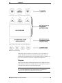
S7SIMATIC Hierarchy in the DAServer Manager
Note Before attempting to configure your S7SIMATIC DAServer, you should
determine the hierarchical structure of your network/PLC environment.
S7SIMATIC DAServer User’s Guide
20
Chapter 2
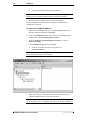
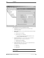
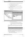
CP Object
The server-specific configuration portion of the S7SIMATIC DAServer
hierarchy tree under the DAServer Manager starts at the CP (Communications
Processor) object. It is a logical representation of the PROFIBUS/HI Industrial
Ethernet port for CP communications in a computer.
•
Up to 128 of these CP objects can be created from the global
Configuration branch.
•
Rename this object as appropriate.
Important! If you subsequently clear your configuration hierarchy, you must
create this CP port object by right-clicking on the Configuration object and
selecting Add CP Object. An object called New_CP_000 Parameters is
created. Rename as appropriate. From this point, all of the following
instructions apply.
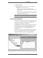
The following figure illustrates the New_CP_000 Parameters configuration
view (right pane).
The New_CP_000 Parameters configuration view has one element to
configure:
•
CP Name: Select the name of the Communications Processor of the PLC
from the drop-down menu.
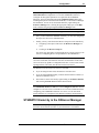
VFD Object
From the New_CP_000 branch of the DAServer hierarchy, the Virtual Field
Device object, generically named New_VFD_000, can be created.
To add Virtual Field Device object to your S7SIMATIC hierarchy
1.
Select your New_CP_000 object and right-click on it.
2.
Select Add VFD Object from the shortcut menu.
S7SIMATIC DAServer User’s Guide
Configuration
3.
21
Rename as appropriate.
•
The New_VFD_000 Parameters configuration view is displayed.
There is one element in the New_VFD_000 Parameters configuration view to
configure:
•
VFD: Select the name of the Virtual Field Device of the PLC from the
drop-down menu.
Note If you happen to see that the drop-down VFD box is blank, make sure
that you have selected the correct CP Name in the CP Name box of the CP
Object Parameters configuration view.
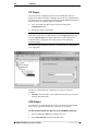
CON Object
From the New_VFD_000 branch of the S7SIMATIC DAServer hierarchy, the
Connection object, generically named New_CON_000, can be created.
To add Connection object to your S7SIMATIC hierarchy
1.
Select your New_VFD_000 object and right-click on it.
2.
Select Add CON Object from the shortcut menu.
3.
Rename as appropriate.
•
The New_CON_000 Parameters configuration view is displayed.
S7SIMATIC DAServer User’s Guide
22
Chapter 2
This configuration view has four configurable elements:
•
Connection: From the drop-down menu, select the name of the
Connection on the PLC.
•
Message Timeout: Enter a value in milliseconds beyond which messages
will time out.
•
•
The default value is 60,000 ms.
Allowable range is 0 to 100,000 ms.
•
•
Connection Timeout: Enter a value in milliseconds beyond which a
pending request to initiate a connection will time out.
•
•
•
If you decrease this value, the S7SIMATIC DAServer reacts
faster to a communications failure.
The default value is 90,000 ms.
Allowable range is 0 to 100,000 ms.
Alarms and Events: Enable Alarms or Events, or disable both for this
connection by clicking on its option button.
•
•
•
Disable All
Enable Alarms
Enable Events
Note On one SIMATIC NET connection, either Alarms, or Events, or none
can be configured.
S7SIMATIC DAServer User’s Guide
Configuration
23
Note If you need to access both Alarms and Events, two different connections
(CONs) have to be created.
The logical endpoint for each branch of the S7SIMATIC hierarchy tree is a
hardware device (PLC).
Note The default name created from adding a hierarchy object is in the format
of New_ObjectName_###, where ObjectName is the name of the object type
and ### is a numeric value starting from "000" enumerated sequentially per
hierarchy object. The link name for the OPC items is constructed by
assembling the respective object names of the nodes along the hierarchy tree in
the logical order, starting from the CP root of this DAServer down to the leaf.
Therefore, the link name is always unique for the DAServer.
Note In order to use the DAServer, you must activate it. See the DAServer
Manager documentation for information about how to activate and deactivate
the DAServer.
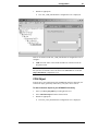
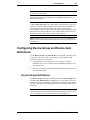
Configuring Device-Group and Device-Item
Definitions
Use the Device Groups tab or Device Items tab in the DAServer Manager user
interface to create new, modify, or delete device-group and device-item
definitions for an object, respectively.
•
For DDE/SuiteLink communications, one or more device-group
definitions must exist for each PLC that the S7SIMATIC DAServer will
communicate with.
•
Each device-group (topic) definition should contain a unique name for the
PLC associated with it.
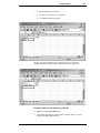
Device-Group Definitions
The Device Groups dialog box, invoked by clicking the Device Groups tab in
the New_CON_000 Parameters configuration view, is the place where device
groups are created or added, deleted, and defined. Configuring default update
intervals for the objects and editing update intervals are also performed in this
dialog box.
Note When you add a new device group, enter a unique name (up to 32
characters long). When you select another part of the DAServer tree hierarchy,
you are prompted to save the modifications to the configuration set.
S7SIMATIC DAServer User’s Guide
24
Chapter 2
To create or add device groups
1.
Right-click in the Device Groups box.
2.
Select the Add command from the shortcut menu.
•
When you add a new device group, enter a unique name (up to 32
characters long).
To delete device groups
1.
Right-click on the device group to be deleted from the list.
2.
Select the Delete command from the shortcut menu.
Note When you select another part of the S7SIMATIC DAServer tree
hierarchy, you are prompted to save the modifications to the configuration set.
To make edits on device groups
1.
Make edits on a device group by right-clicking on the device group to be
edited.
2.
Select Edit from the shortcut menu to open the Device Group
Parameters dialog box.
S7SIMATIC DAServer User’s Guide
Configuration
3.
25
Make the necessary edits.
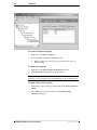
This Edit dialog box contains the following five configurable elements:
•
Poke Mode: Choose one of three settings to tune the poking behavior to
the PLC.
•
•
•
Control mode
Transition mode
Full optimization
Note The default Poke Mode settings for the S7SIMATIC DAServer is
Transition mode.
•
Cyclic Services: If Cyclic Services is utilized (the Disable S7 cyclic
services: option button is not selected), two additional settings must be
configured:
•
•
•
Maximum available
Limit cyclic services to
If you know how many services the remote PLC can handle, you can
limit the use of cyclic services in this device group and distribute the
available cyclic services among the device groups associated with this
connection. Otherwise, you can use the maximum available services.
•
•
Allowable range for Limit cyclic services to is 0 to 150.
The default is 0.
S7SIMATIC DAServer User’s Guide
26
Chapter 2
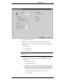
•
•
Click on Disable S7 cyclic services: to disable the S7 SAPI cyclic
services for the device group.
•
Cyclic services have a reliable update frequency and need less
bus access.
•
They are a limited resource in the PLC and/or Communications
Processor.
•
If the Disable S7 cyclic services: option button is selected, the
S7SIMATIC DAServer polls all topics in this device group.
If this option button is not selected, the S7SIMATIC DAServer tries
to register as many topics in the cyclic services as possible.
•
If there are insufficient credits for cyclic services left, the
S7SIMATIC DAServer creates poll messages instead of cyclic
messages for the remaining topics.
•
Reasons for disabling Cyclic Services include the following:
•
A device group with a long update interval. (It should not occupy
the cyclic services resource.)
•
When you need to force the S7SIMATIC DAServer to attempt to
collect data faster than 100 milliseconds.
Block Services: If the Block Services function is required, in the Block
Services box there are two settings that must be configured:
•
•
Initial Values Timeout
Update Timeout
•
Time-outs are needed for Block Services to supervise the reading of
initial values and updating the block items to this connection. A timeout value of 0 disables the time supervision of block messages.
•
Block services are unconfirmed services. If the remote station does
not send data within this time range, the Block Services is
reinitialized and an error message is logged.
•
Peripheral Access: Select the Read Contiguous IO check box to force
the S7SIMATIC DAServer to read input and output blocks (also
peripherals), only if their address spaces are contiguous.
Select this check box if you have some holes in your PLC's input-address
or output-address space.
•
Optimization: To configure the optimization mode the S7SIMATIC
DAServer should use to acquire data from the PLC, select one of these
settings:
•
•
•
S7 SAPI
Block read
Auto
To configure default update intervals
1.
To configure a default update interval for the object, right-click in the
Device Groups box.
2.
Select Config Default Update Interval from the shortcut menu.
S7SIMATIC DAServer User’s Guide
Configuration
27
To edit update intervals
•
To edit the update interval for an object, double-click its value in the
Update Interval column and make the edits.
•
Update Interval is the frequency (in milliseconds) that the
S7SIMATIC DAServer acquires data from the topics associated with
that device group.
•
Different topics can be polled at different rates in a PLC by defining
multiple device-group names for the same PLC and setting a different
Update Interval for each device group.
Note When you select another part of the S7SIMATIC DAServer tree
hierarchy, you are prompted to save the modifications to the configuration set.
Device-Item Definitions
The predefined item syntax/name for the S7 PLC cannot be changed. However,
to make it easier to remember item names, the DAServer enables you to create
aliases for these item names. For example, it may be easier for you to
remember the item syntax "mb80" as "Temperature."
The Device Items tab in the DAServer Manager user interface is used to create
new, modify, delete, export, or import device-item definitions for an object.
The configuration is performed in the Device Items dialog box, invoked by
clicking the Device Items tab in the New_S7Cp_000 Parameters
configuration view.
Once the Device Items feature is utilized to configure item names, it provides
the DAServer with the capability to perform OPC Item browsing. When the
DAServer is running and an OPC Client requests item information, the
configured items will show up under the CON Object hierarchy node.
S7SIMATIC DAServer User’s Guide
28
Chapter 2
To create or add device items
1.
Right-click in the Device Items box.
2.
Select the Add command from the shortcut menu.
3.
Type in the item name of your choice in the Name column.
•
•
4.
For example, "Clock."
When you add a new device item, enter a unique name (up to 32
characters long).
Double-click the line on the Item Reference column and enter the
correlated item reference for the name you have just selected.
•
For example, "mb90."
Note If the name and the item reference is the same, it is only necessary
to enter a name. The DAServer will assume that the item reference is the
same. This may be necessary if you want to add some items for browsing
via OPC, even if they do not have a symbolic name.
To rename device items
1.
Rename a device item by right-clicking on the device item to be
renamed.
2.
Select Rename from the shortcut menu, then make the changes.
To delete device items
1.
Right-click on the device item to be deleted from the list.
2.
Select the Delete command from the shortcut menu.
To clear all device items
1.
Right-click in the Device Items box.
2.
Select the Clear All command from the shortcut menu.
•
All the device items listed will be cleared after you confirm their
deletion.
The Export and Import commands on the shortcut menu enable you to export
and import the DAServer item data to and from a CSV file, after the
configuration of the Device Items has been completed. These commands will
allow you to perform an off-line, large-scale edit on the item data configured
for a PLC, and import what has been edited back into the PLC configuration.
To export DAServer item data to a CSV file
1.
Right-click in the Device Items box.
2.
Select the Export command from the shortcut menu.
•
•
The standard Save As dialog box appears.
The file name has defaulted into "PLC Hierarchyname.csv," within
the current-system-configured default directory.
S7SIMATIC DAServer User’s Guide
Configuration
3.
29
Accept the defaults to save the file.
•
•
The file is saved as New_CON_000.csv.
It is editable in Microsoft Excel.
The file can now be edited off-line. It contains one row for each item
configured with two columns, Name and Item Reference, respectively.
To import DAServer item data from a CSV file
1.
Right-click in the Device Items box.
2.
Clear all the item data you wish to replace with the edited .csv file by
selecting the Clear All command.
S7SIMATIC DAServer User’s Guide
30
Chapter 2
•
3.
Select the Import command from the shortcut menu.
•
•
4.
The data will be cleared after you click on Yes to confirm the deletion.
The standard Open dialog box appears.
It defaults to the .csv file extension within the current-systemconfigured default directory.
Browse for the .csv file you want to import, select it, then press the OK
button for confirmation.
•
The DAServer manager will import the file and deposit it in the
Device Items box.
•
During the imported file processing:
•
•
New item references will be added based on unique names.
If there are duplicate names, you will be provided with the ability
to replace the existing entry with the new entry, or ignore the new
entry.
When the DAServer is running and an OPC client requests item information,
the imported configured items will show up under the Con Object hierarchy
node.
Note When you select another part of the S7SIMATIC DAServer tree
hierarchy, you are prompted to save the modifications to the configuration set.
Each configuration view associated with objects in the S7SIMATIC DAServer
hierarchy tree has a common feature, the Save button located on the upper
right corner of the configuration view.
1.
When you modify any Parameters, or Device Groups dialog box, click
Save to implement the new modifications.
S7SIMATIC DAServer User’s Guide
Configuration
•
2.
31
If you do not click Save, the configuration is reset to its original
condition (since the last save).
After all modifications, you must save when prompted for the new data to
be saved to the configuration set.
Scan-Based Message Handling
Wonderware S7SIMATIC DAServers are based on the concept of polling a
hardware device for information. This polling is driven by a need which is
expressed in the form of requests from one or more clients. Once a particular
piece of information has been requested by a client, the S7SIMATIC DAServer
formulates its own request and sends that request to the hardware device. The
S7SIMATIC DAServer then waits for a response to its request. Once the
information has been received, the S7SIMATIC DAServer passes that
information back to the client, and repeats the process until all clients have
ceased requesting information.
The rate at which the S7SIMATIC DAServer will poll a particular device for a
specific piece of information is defined in the device group (topic definition)
inside the S7SIMATIC DAServer, using a parameter called the Update
Interval. When setting this parameter, there is always a trade-off between the
update speed of the device group and the resulting decrease in system
responsiveness.
Since you more than likely want very fast response, the temptation is to set the
Update Interval to a value close to 0 (zero) seconds. However, if every point is
polled at this rate, the entire system will suffer due to slow response time.
Therefore, you should compromise, and set the Update Interval to a more
reasonable value. You could also create multiple device groups for each
device, setting the Update Interval to different values, then assigning different
items to different device groups, depending on how quickly the values change
and how quickly you want to see an update of those changes.
Unsolicited Message Handling
The S7SIMATIC DAServer will process the following three types of
unsolicited messages sent by the S7 PLCs:
•
•
•
Alarms
Events
Block Services
Alarms and Events
In the world of PLCs and DAServers, it is obvious that a PLC will know when
a critical event has occurred before the DAServer will have a chance to poll for
that data. Therefore, it would seem natural that if a critical event occurs, the
PLC should have the capability to inform the DAServer immediately, without
having to wait for the DAServer to poll it.
S7SIMATIC DAServer User’s Guide
32
Chapter 2
This is the role of an unsolicited message. Once a PLC has determined that a
critical condition exists, it can generate a message immediately sent to the
DAServer without a prior request from the DAServer. The unsolicited message
implementation requires both the messaging instructions properly programmed
in the PLC logic and the device group appropriately configured in the
DAServer.
Block Services
In addition to unsolicited messages based on critical conditions or events, S7
PLCs are also capable of handling another type of unsolicited messages:
"Block Services."
Block Services can be used to send blocks of data up to 64Kbps within one
send job. This can be triggered by a timer, an event, an I/O activity, or initiated
via a program code.
Archiving Configuration Sets
After you have configured your DAServer, you can archive that specific
configuration. You can archive more than one configuration set, and
subsequently choose different configurations for different purposes.
To archive configuration sets
1.
In the DAServer Manager, right-click on the Configuration node in the
hierarchy below your DAServer.
2.
Select Archive Configuration Set from the shortcut menu.
3.
In the Archive Configuration Set dialog box, provide a Configuration Set
Name.
4.
Click Archive.
•
All current configuration values are saved to the archived set.
Once you have archived at least one configuration set, you can select it for use.
To use different configuration sets from the current one
1.
In the DAServer Manager, right-click the Configuration node in the
hierarchy below your DAServer.
2.
Select Use Another Configuration Set from the shortcut menu and click
on a configuration set in the sub-menu.
•
All parameters in the DAServer configuration hierarchy change to the
chosen configuration set.
Hot Configuration
If a parameter value change takes effect right away while the DAServer is
running, the parameter is a hot-configurable parameter. Certain parameters in
the S7SIMATIC DAServer are hot-configurable. Incorporated in the DAServer
are the following hot-configuration functionalities:
S7SIMATIC DAServer User’s Guide
Configuration
33
•
•
Modifying Global Configuration parameters.
•
Adding, deleting, or modifying device groups, the Update Interval column
in the Device Groups tab, and device items.
Adding, deleting, or modifying device nodes (without affecting any other
device nodes, excluding the children of the modified device nodes).
All other parameters are not hot-configurable. To have those changes take
effect, you have to restart the DAServer.
Note If changes are made to server-specific parameters while the server is
active, the DAServer will issue a warning message to the logger.
S7SIMATIC DAServer User’s Guide
34
Chapter 2
S7SIMATIC DAServer User’s Guide
Item Names
C H A P T E R
35
3
Item Names
The Wonderware S7SIMATIC DAServer uses an item-naming convention
based on the two-letter data-type identifiers used by SIMATIC NET. This
convention differs slightly from the convention used for programming Siemens
PLCs. The following tables describe the item naming for the Siemens S7
200/300/400 family of PLCs.
Contents
• Address Space
• Data Blocks and Instance Blocks
• Flag Bytes
• Input Bytes
• Output Bytes
• Peripheral Input Bytes
• Peripheral Output Bytes
• Counters
• Timers
• Block Items
• Alarms and Events
• Conversions and Suffixes of Items
• DAServer Standard System Items
• Generic OPC Syntax
Address Space
Items are defined within the S7SIMATIC DAServer address space. The items
of the S7SIMATIC DAServer consist of the Communications Processor, the
Virtual Field Device, the Connection, and specific items separated by a
delimiter. See the following examples.
OPC Example:
OPC Access Path/Device Group Name in the client: S7400_sn_100
Item in the client: board1.vfd1.connection1.DB100,W0
S7SIMATIC DAServer User’s Guide
36
Chapter 3
In the above example:
The name of the access path (device group) is S7400_sn_100.
The name of the Communications Processor is board1.
The name of the Virtual Field Device is vfd1.
The name of the Connection is connection1.
The name of the item is DB100,W0. It is a word with address 0 of the data
block 100.
All properties are delimited by a "." (period).
Note It is not necessary to use an OPC access path. Without an OPC access
path, the default OPC device group is being used.
DDE/SuiteLink Example:
Topic in the client: S7400_sn_100
Item in the client: DB100,W0
In the above example:
The name of the topic (device group) is S7400_sn_100.
For DDE/SuiteLink communications, there must be no path
information in the item name.
The path is determined by the device group, if all device groups have
unique names. (See Configuring Device-Group and Device-Item
Definitions.)
The name of the item is DB100,W0. It is a word with address 0 of the data
block 100.
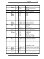
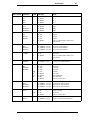
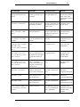
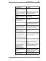
Data Blocks and Instance Blocks
The following table summarizes the data format, item or point, suffix, data
type, and range for Data Blocks and Instance Block.
Data Format Item/Point
Suffix
Data Type
Range
Bit
D<B,I>d,Xx.y
VT_BOOL
0 or 1
String
D<B,I>d,Sx,v
D<B,I>d,STRINGx,v
VT_BSTR
VT_BSTR
String
String
S7String
D<B,I>d,S7Sx,w
D<B,I>d,S7STRINGx,w
VT_BSTR
VT_BSTR
String
String
Byte
D<B,I>d,Bx
D<B,I>d,BYTEx
VT_UI1
VT_UI1
VT_BSTR
0 to 255
0 to 255
1990-1-1-0:00:00.000 to 2089-1231-23:59:59.999
DT
Byte Array
D<B,I>d,Bx,v
D<B,I>d,BYTEx,v
Char
D<B,I>d,CHARx
VT_ARRAY: VT_UI1 0 to 255 for each element*
VT_ARRAY: VT_UI1 0 to 255 for each element*
DT
S7SIMATIC DAServer User’s Guide
VT_I1
VT_BSTR
-128 to 127
1990-1-1-0:00:00.000 to 2089-1231-23:59:59.999
Item Names
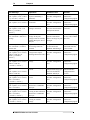
Data Format Item/Point
Suffix
Data Type
Range
37
Char Array
D<B,I>d,CHARx,v
VT_ARRAY: VT_I1
-128 to 127 for each element*
Word
D<B,I>d,Wn
D<B,I>d,WORDn
VT_UI2
VT_UI2
VT_UI2
VT_BSTR
VT_BSTR
VT_R4
VT_BSTR
0 to 65535
0 to 65535
0 to 9999
0.0 to 999.3
0ms to 2h46m30s
0.0 to 9990.0 (s)
1990-1-1 to 2168-12-31
BCD
KT
S5T
TR
D
Word Array
D<B,I>d,Wn,v
D<B,I>d,WORDn,v
Integer
D<B,I>d,INTn
VT_ARRAY: VT_UI2 0 to 65535 for each element*
VT_ARRAY: VT_UI2 0 to 65535 for each element*
BCD
D
VT_I2
VT_I2
VT_BSTR
-32768 to 32767
-999 to 999
1990-1-1 to 2168-12-31
Integer Array
D<B,I>d,INTn,v
VT_ARRAY: VT_I2
-32768 to 32767 for each element*
Double Word
D<B,I>d,Dm
D<B,I>d,DWORDm
VT_UI4
VT_UI4
VT_UI4
VT_BSTR
VT_BSTR
0 to 4294967295**
0 to 4294967295**
0 to 99999999
0:00:00.000 to 23:59:59.999
-24D_20H_31M_ 23S_648MS to
24D_20H_31M_23S_647MS
BCD
TOD
T
Double Word
Array
D<B,I>d,Dm,v
D<B,I>d,DWORDm,v
VT_ARRAY: VT_UI4 0 to 4294967295 for each element*
VT_ARRAY: VT_UI4 0 to 4294967295 for each element*
VT_I4
VT_I4
VT_BSTR
VT_BSTR
-2147483648 to 2147483647
-9999999 to 9999999
0:00:00.000 to 23:59:59.999
-24D_20H_31M_ 23S_648MS to
24D_20H_31M_23S_647MS
Double Integer D<B,I>d,DINTm,v
Array
VT_ARRAY: VT_I4
-2147483648 to 2147483647 for
each element*
Real
D<B,I>d,REALm
VT_R4
Real Array
D<B,I>d,REALm,v
VT_ARRAY: VT_R4
-3.4e38 to 3.4e38
-3.4e38 to 3.4e38 for each element*
Double Integer D<B,I>d,DINTm
BCD
TOD
T
Note *: For DDE/SuiteLink, the item value is the HexASCII representation of
the complete array. The result is one string containing all the elements of the
array in the HexASCII representation of the binary data. In this case, the
datatype is Message (VT_BSTR).
**: For DDE/SuiteLink, this value is restricted to the range 0 to 2147483647.
Values higher than that will be clamped to the maximum value of 2147483647
in a SuiteLink or DDE client. In this case, the quality of the item shows
"Clamp High."
Where:
d
is the data block number, with a range from 1 to 65535.
x
is the start address, with a range from 0 to 65535.
S7SIMATIC DAServer User’s Guide
38
Chapter 3
Where:
y
is the bit position, with a range from 0 to 7.
•
•
0 is the least significant bit.
7 is the most significant bit.
v
denotes the length of data in bytes, with a range from 1 to (net
PDU data size/type size - header information).
w
denotes the length of the net S7 string-data in characters, with a
range from 1 to (net PDU data size/type size - header
information - 1).
The size in S7 message is w+1.
The size of string representation in S7 PLC is w+2.
n
is the start address of 2-byte data/2-byte data arrays, with a
range from 0 to 65534.
m
is the start address of 4-byte data/4-byte data arrays, with a
range from 0 to 65532.
Note All data blocks are Read/Write. The longest string or array that can be
read in a cyclic service has the length of the PDU size minus 32 bytes. The
longest string InTouch can process is 131 bytes. The longest string that can be
poked is 256 bytes or the PDU size minus 28 bytes, whichever is less. The
S7SIMATIC DAServer processes a write (POKE) to a Data Block.
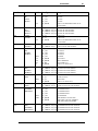
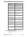
Flag Bytes
Data format, item or point, suffix, data type, and range are summarized in the
following table for Flag Bytes.
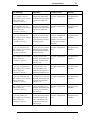
Data Format Item/Point
Bit
FXx.y
MXx.y
String
FSx,v
MSx,v
FSTRINGx,v
MSTRINGx,v
Byte
FBx
MBx
FBYTEx
MBYTEx
Byte Array
FBx,v
MBx,v
FBYTEx,v
MBYTEx,v
Suffix Data Type
VT_BOOL
VT_BOOL
VT_BSTR
VT_BSTR
VT_BSTR
VT_BSTR
VT_UI1
VT_UI1
VT_UI1
VT_UI1
VT_BSTR
DT
VT_ARRAY: VT_UI1
VT_ARRAY: VT_UI1
VT_ARRAY: VT_UI1
VT_ARRAY: VT_UI1
S7SIMATIC DAServer User’s Guide
Range
0 or 1
0 or 1
String
String
String
String
0 to 255
0 to 255
0 to 255
0 to 255
1990-1-1-0:00:00.000 to 2089-12-3123:59:59.999
0 to 255 for each element*
0 to 255 for each element*
0 to 255 for each element*
0 to 255 for each element*
Item Names
Data Format Item/Point
Char
FCHARx
MCHARx
Char Array
Word
Suffix Data Type
VT_I1
VT_I1
DT
VT_BSTR
FCHARx,v
MCHARx,v
FWn
MWn
FWORDn
MWORDn
BCD
TOD
T
VT_ARRAY: VT_I1
VT_ARRAY: VT_I1
VT_UI2
VT_UI2
VT_UI2
VT_UI2
VT_UI2
VT_BSTR
VT_BSTR
VT_R4
VT_BSTR
VT_ARRAY: VT_UI2
VT_ARRAY: VT_UI2
VT_ARRAY: VT_UI2
VT_ARRAY: VT_UI2
VT_I2
VT_I2
VT_I2
VT_BSTR
VT_ARRAY: VT_I2
VT_ARRAY: VT_I2
VT_UI4
VT_UI4
VT_UI4
VT_UI4
VT_UI4
VT_BSTR
VT_BSTR
BCD
TOD
T
VT_ARRAY: VT_UI4
VT_ARRAY: VT_UI4
VT_ARRAY: VT_UI4
VT_ARRAY: VT_UI4
VT_14
VT_14
VT_14
VT_BSTR
VT_BSTR
BCD
KT
S5T
TR
D
Word Array
Integer
Integer Array
Double Word
FWn,v
MWn,v
FWORDn,v
MWORDn,v
FINTn
MINTn
FINTn,v
MINTn,v
FDm
MDm
FDWORDm
MDWORDm
Double Word
Array
FDm,v
MDm,v
FDWORDm,v
MDWORDm,v
Double Integer FDINTm
MDINTm
Double Integer FDINTm,v
Array
MDINTm,v
Real
FREALm
MREALm
VT_ARRAY: VT_I4
VT_ARRAY: VT_I4
VT_R4
VT_R4
Real Array
VT_ARRAY: VT_R4
VT_ARRAY: VT_R4
FREALm,v
MREALm,v
39
Range
-128 to 127
-128 to 127
1990-1-1-0:00:00.000 to 2089-12-3123:59:59.999
-128 to 127 for each element*
-128 to 127 for each element*
0 to 65535
0 to 65535
0 to 65535
0 to 65535
0 to 9999
0.0 to 999.3
0ms to 2h46m30s
0.0 to 9990.0 (s)
1990-1-1 to 2168-12-31
0 to 65535 for each element*
0 to 65535 for each element*
0 to 65535 for each element*
0 to 65535 for each element*
-32768 to 32767
-32768 to 32767
-999 to 999
1990-1-1 to 2168-12-31
-32768 to 32767 for each element*
-32768 to 32767 for each element*
0 to 4294967295**
0 to 4294967295**
0 to 4294967295**
0 to 4294967295**
0 to 9999999
0:00:00.000 to 23:59:59.999
-24D_20H_31M_ 23S_648MS to
24D_20H_31M_23S_647MS
0 to 4294967295 for each element*
0 to 4294967295 for each element*
0 to 4294967295 for each element*
0 to 4294967295 for each element*
-2147483648 to 2147483647
-2147483648 to 2147483647
-9999999 to 9999999
0:00:00.000 to 23:59:59.999
-24D_20H_31M_ 23S_648MS to
24D_20H_31M_23S_647MS
-2147483648 to 2147483647 for each element*
-2147483648 to 2147483647 for each element*
-3.4e38 to 3.4e38
-3.4e38 to 3.4e38
-3.4e38 to 3.4e38 for each element*
-3.4e38 to 3.4e38 for each element*
S7SIMATIC DAServer User’s Guide
40
Chapter 3
Note *: For DDE/SuiteLink, the item value is the HexASCII representation of
the complete array. The result is one string containing all the elements of the
array in the HexASCII representation of the binary data in big-endian format.
In this case, the datatype is Message (VT_BSTR).
**: For DDE/SuiteLink, this value is restricted to the range 0 to 2147483647.
Values higher than that will be clamped to the maximum value of 2147483647
in a SuiteLink or DDE client. In this case, the quality of the item shows
"Clamp High."
Where:
x
is the start address, with a range from 0 to 65535.
y
is the bit position, with a range from 0 to 7.
•
•
0 is the least significant bit.
7 is the most significant bit.
v
denotes the length of data in bytes, with a range from 1 to (net
PDU data size/type size - header information).
n
is the start address of 2-byte data/2-byte data arrays, with a
range from 0 to 65534.
m
is the start address of 4-byte data/4-byte data arrays, with a
range from 0 to 65532.
Note All flags are Read/Write. The longest string or array that can be read in
a cyclic service has the length of the PDU size minus 32 bytes. The longest
string InTouch can process is 131 bytes. The longest string that can be poked is
256 bytes or the PDU size minus 28 bytes, whichever is less. The S7SIMATIC
DAServer processes a write (POKE) to a Flag Byte.
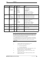
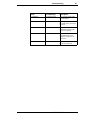
Input Bytes
The following table summarizes the data format, item or point, suffix, data
type, and range for Input Bytes.
Data Format Item/Point
Bit
Ix.y
Ex.y
IXx.y
EXx.y
String
ISx,v
ESx,v
ISTRINGx,v
ESTRINGx,v
Suffix
Data Type
VT_BOOL
VT_BOOL
VT_BOOL
VT_BOOL
VT_BSTR
VT_BSTR
VT_BSTR
VT_BSTR
S7SIMATIC DAServer User’s Guide
Range
0 or 1
0 or 1
0 or 1
0 or 1
String
String
String
String
Item Names
Data Format Item/Point
Byte
IBx
EBx
IBYTEx
EBYTEx
Byte Array
Char
Char Array
Word
Suffix
DT
Data Type
VT_UI1
VT_UI1
VT_UI1
VT_UI1
VT_BSTR
DT
VT_ARRAY: VT_UI1
VT_ARRAY: VT_UI1
VT_ARRAY: VT_UI1
VT_ARRAY: VT_UI1
VT_I1
VT_I1
VT_BSTR
IBx,v
EBx,v
IBYTEx,v
EBYTEx,v
ICHARx
ECHARx
ICHARx,v
ECHARx,v
IWn
EWn
IWORDn
EWORDn
BCD
KT
S5T
TR
D
Word Array
Integer
IWn,v
EWn,v
IWORDn,v
EWORDn,v
IINTn
EINTn
BCD
D
Integer Array
Double Word
IINTn,v
EINTn,v
IDmEDm
IDWORDm
EDWORDm
BCD
TOD
T
Double Word
Array
IDm,v
EDm,v
IDWORDm,v
EDWORDm,v
VT_ARRAY: VT_I1
VT_ARRAY: VT_I1
VT_UI2
VT_UI2
VT_UI2
VT_UI2
VT_UI2
VT_BSTR
VT_BSTR
VT_R4
VT_BSTR
VT_ARRAY: VT_UI2
VT_ARRAY: VT_UI2
VT_ARRAY: VT_UI2
VT_ARRAY: VT_UI2
VT_I2
VT_I2
VT_I2
VT_BSTR
VT_ARRAY: VT_I2
VT_ARRAY: VT_I2
VT_UI4
VT_UI4
VT_UI4
VT_UI4
VT_UI4
VT_BSTR
VT_BSTR
VT_ARRAY: VT_UI4
VT_ARRAY: VT_UI4
VT_ARRAY: VT_UI4
VT_ARRAY: VT_UI4
41
Range
0 to 255
0 to 255
0 to 255
0 to 255
1990-1-1-0:00:00.000 to 2089-12-3123:59:59.999
0 to 255 for each element*
0 to 255 for each element*
0 to 255 for each element*
0 to 255 for each element*
-128 to 127
-128 to 127
1990-1-1-0:00:00.000 to 2089-12-3123:59:59.999
-128 to 127 for each element*
-128 to 127 for each element*
0 to 65535
0 to 65535
0 to 65535
0 to 65535
0 to 9999
0.0 to 999.3
0ms to 2h46m30s
0.0 to 9990.0 (s)
1990-1-1 to 2168-12-31
0 to 65535 for each element*
0 to 65535 for each element*
0 to 65535 for each element*
0 to 65535 for each element*
-32768 to 32767
-32768 to 32767
-999 to 999
1990-1-1 to 2168-12-31
-32768 to 32767 for each element*
-32768 to 32767 for each element*
0 to 4294967295**
0 to 4294967295**
0 to 4294967295**
0 to 4294967295**
0 to 99999999
0:00:00.000 to 23:59:59.999
-24D_20H_31M_23S_648MS to
24D_20H_31M_23S_647MS
0 to 4294967295 for each element*
0 to 4294967295 for each element*
0 to 4294967295 for each element*
0 to 4294967295 for each element*
S7SIMATIC DAServer User’s Guide
42
Chapter 3
Data Format Item/Point
Double Integer IDINTm
EDINTm
Suffix
BCD
TOD
T
Double Integer IDINTm,v
Array
EDINTm,v
Real
IREALm
EREALm
Real Array
Data Type
VT_UI4
VT_UI4
VT_UI4
VT_BSTR
VT_BSTR
VT_ARRAY: VT_I4
VT_ARRAY: VT_I4
VT_R4
VT_R4
Range
-2147483648 to 2147483647
-2147483648 to 2147483647
-9999999 to 9999999
0:00:00.000 to 23:59:59.999
-24D_20H_31M_23S_ 648MS to 24D_20H_
31M_23S_647MS
-2147483648 to 2147483647 for each element*
-2147483648 to 2147483647 for each element*
-3.4e38 to 3.4e38
-3.4e38 to 3.4e38
VT_ARRAY: VT_R4 -3.4e38 to 3.4e38 for each element*
VT_ARRAY: VT_R4 -3.4e38 to 3.4e38 for each element*
IREALm,v
EREALm,v
Note *: For DDE/SuiteLink, the item value is the HexASCII representation of
the complete array. The result is one string containing all the elements of the
array in the HexASCII representation of the binary data in big-endian format.
In this case, the datatype is Message (VT_BSTR).
**: For DDE/SuiteLink, this value is restricted to the range 0 to 2147483647.
Values higher than that will be clamped to the maximum value of 2147483647
in a SuiteLink or DDE client. In this case, the quality of the item shows
"Clamp High."
Where:
x
is the start address, with a range from 0 to 65535.
y
is the bit position, with a range from 0 to 7.
•
•
0 is the least significant bit.
7 is the most significant bit.
v
denotes the length of data in bytes, with a range from 1 to (net
PDU data size/type size - header information).
n
is the start address of 2-byte data/2-byte data arrays, with a
range from 0 to 65534.
m
is the start address of 4-byte data/4-byte data arrays, with a
range from 0 to 65532.
Note All inputs are Read-only. The longest string or array that can be read in
a cyclic service has the length of the PDU size minus 32 bytes. The longest
string InTouch can process is 131 bytes. The S7SIMATIC DAServer does not
process a write (POKE) to an Input Byte.
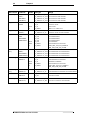
Output Bytes
Data format, item or point, suffix, data type, and range are summarized in the
following table for Output Bytes.
S7SIMATIC DAServer User’s Guide
Item Names
Data Format Item/Point
Suffix Data Type
Range
Bit
Ox.y
Ax.y
OXx.y
AXx.y
VT_BOOL
VT_BOOL
VT_BOOL
VT_BOOL
0 or 1
0 or 1
0 or 1
0 or 1
String
OSx,v
ASx,v
OSTRINGx,v
ASTRINGx,v
VT_BSTR
VT_BSTR
VT_BSTR
VT_BSTR
String
String
String
String
Byte
OBx
ABx
OBYTEx
ABYTEx
VT_UI1
VT_UI1
VT_UI1
VT_UI1
VT_BSTR
0 to 255
0 to 255
0 to 255
0 to 255
1990-1-1-0:00:00.000 to 2089-12-3123:59:59.999
DT
Byte Array
OBx,v
ABx,v
OBYTEx,v
ABYTEx,v
VT_ARRAY: VT_UI1
VT_ARRAY: VT_UI1
VT_ARRAY: VT_UI1
VT_ARRAY: VT_UI1
0 to 255 for each element*
0 to 255 for each element*
0 to 255 for each element*
0 to 255 for each element*
Char
OCHARx
ACHARx
VT_I1
VT_I1
VT_BSTR
-128 to 127
-128 to 127
1990-1-1-0:00:00.000 to 2089-12-3123:59:59.999
DT
Char Array
OCHARx,v
ACHARx,v
VT_ARRAY: VT_I1
VT_ARRAY: VT_I1
-128 to 127 for each element*
-128 to 127 for each element*
Word
OWn
AWn
OWORDn
AWORDn
VT_UI2
VT_UI2
VT_UI2
VT_UI2
VT_UI2
VT_BSTR
VT_BSTR
VT_R4
VT_BSTR
0 to 65535
0 to 65535
0 to 65535
0 to 65535
0 to 9999
0.0 to 999.3
0ms to 2h46m30s
0.0 to 9990.0 (s)
1990-1-1 to 2168-12-31
BCD
KT
S5T
TR
D
Word Array
OWn,v
AWn,v
OWORDn,v
AWORDn,v
VT_ARRAY: VT_UI2
VT_ARRAY: VT_UI2
VT_ARRAY: VT_UI2
VT_ARRAY: VT_UI2
0 to 65535 for each element*
0 to 65535 for each element*
0 to 65535 for each element*
0 to 65535 for each element*
Integer
OINTn
AINTn
VT_I2
VT_I2
VT_I2
VT_BSTR
-32768 to 32767
-32768 to 32768
-999 to 999
1990-1-1 to 2168-12-31
VT_ARRAY: VT_I2
VT_ARRAY: VT_I2
-32768 to 32767 for each element*
-32768 to 32768 for each element*
BCD
D
Integer Array
OINTn,v
AINTn,v
43
S7SIMATIC DAServer User’s Guide
44
Chapter 3
Data Format Item/Point
Suffix Data Type
Range
VT_UI4
VT_UI4
VT_UI4
VT_UI4
VT_UI4
VT_BSTR
VT_BSTR
0 to 4294967295**
0 to 4294967295**
0 to 4294967295**
0 to 4294967295**
0 to 99999999
0:00:00.000 to 23:59:59.999
-24D_20H_31M_23S_648MS to
24D_20H_31M_23S_647MS
VT_ARRAY: VT_UI4
VT_ARRAY: VT_UI4
VT_ARRAY: VT_UI4
VT_ARRAY: VT_UI4
0 to 4294967295 for each element*
0 to 4294967295 for each element*
0 to 4294967295 for each element*
0 to 4294967295 for each element*
VT_I4
VT_I4
VT_I4
VT_BSTR
VT_BSTR
-2147483648 to 2147483647
-2147483648 to 2147483647
-9999999 to 9999999
0:00:00.000 to 23:59:59.999
-24D_20H_31M_23S_ 648MS to
24D_20H_31M_23S_ 647MS
Double Integer ODINTm,v
Array
ADINTm,v
VT_ARRAY: VT_I4
VT_ARRAY: VT_I4
-2147483648 to 2147483647 for each element*
-2147483648 to 2147483647 for each element*
Real
OREALm
AREALm
VT_R4
VT_R4
Real Array
OREALm,v
AREALm,v
VT_ARRAY: VT_R4
VT_ARRAY: VT_R4
-3.4e38 to 3.4e38
-3.4e38 to 3.4e38
-3.4e38 to 3.4e38 for each element*
-3.4e38 to 3.4e38 for each element*
Double Word
ODm
ADm
ODWORDm
ADWORDm
BCD
TOD
T
Double Word
Array
ODm,v
ADm,v
ODWORDm,v
ADWORDm,v
Double Integer ODINTm
ADINTm
BCD
TOD
T
Note *: For DDE/SuiteLink, the item value is the HexASCII representation of
the complete array. The result is one string containing all the elements of the
array in the HexASCII representation of the binary data in big-endian format.
In this case, the datatype is Message (VT_BSTR).
**: For DDE/SuiteLink, this value is restricted to the range 0 to 2147483647.
Values higher than that will be clamped to the maximum value of 2147483647
in a SuiteLink or DDE client. In this case, the quality of the item shows
"Clamp High."
Where:
x
is the start address, with a range from 0 to 65535.
y
is the bit position, with a range from 0 to 7.
•
•
0 is the least significant bit.
7 is the most significant bit.
v
denotes the length of data in bytes, with a range from 1 to (net
PDU data size/type size - header information).
n
is the start address of 2-byte data/2-byte data arrays, with a
range from 0 to 65534.
m
is the start address of 4-byte data/4-byte data arrays, with a
range from 0 to 65532.
S7SIMATIC DAServer User’s Guide
Item Names
45
Note All outputs are Read/Write. The longest string or array that can be read
in a cyclic service has the length of the PDU size minus 32 bytes. The longest
string InTouch can process is 131 bytes. The longest string that can be poked is
256 bytes or the PDU size minus 28 bytes, whichever is less. The S7SIMATIC
DAServer processes a write (POKE) to an Output Byte.
Peripheral Input Bytes
The following table summarizes the data format, item or point, suffix, data
type, and range for Peripheral Input Bytes.
Data Format Item/Point
Suffix Data Type
Range
Bit
PIx.y
PEx.y
PIXx.y
PEXx.y
VT_BOOL
VT_BOOL
VT_BOOL
VT_BOOL
0 or 1
0 or 1
0 or 1
0 or 1
String
PISx,v
PESx,v
PISTRINGx,v
PESTRINGx,v
VT_BSTR
VT_BSTR
VT_BSTR
VT_BSTR
String
String
String
String
Byte
PIBx
PEBx
PIBYTEx
PEBYTEx
VT_UI1
VT_UI1
VT_UI1
VT_UI1
VT_BSTR
0 to 255
0 to 255
0 to 255
0 to 255
1990-1-1-0:00:00.000 to 2089-12-3123:59:59.999
DT
Byte Array
PIBx,v
PEBx,v
PIBYTEx,v
PEBYTEx,v
VT_ARRAY: VT_UI1
VT_ARRAY: VT_UI1
VT_ARRAY: VT_UI1
VT_ARRAY: VT_UI1
0 to 255 for each element*
0 to 255 for each element*
0 to 255 for each element*
0 to 255 for each element*
Char
PICHARx
PECHARx
VT_I1
VT_I1
VT_BSTR
-128 to 127
-128 to 127
1990-1-1-0:00:00.000 to 2089-12-3123:59:59.999
DT
Char Array
PICHARx,v
PECHARx,v
VT_ARRAY: VT_I1
VT_ARRAY: VT_I1
-128 to 127 for each element*
-128 to 127 for each element*
Word
PIWn
PEWn
PIWORDn
PEWORDn
VT_UI2
VT_UI2
VT_UI2
VT_UI2
VT_UI2
VT_BSTR
VT_BSTR
VT_R4
VT_BSTR
0 to 65535
0 to 65535
0 to 65535
0 to 65535
0 to 9999
0.0 to 999.3
0ms to 2h46m30s
0.0 to 9990.0 (s)
1990-1-1 to 2168-12-31
BCD
KT
S5T
TR
D
S7SIMATIC DAServer User’s Guide
46
Chapter 3
Data Format Item/Point
Suffix Data Type
Range
Word Array
PIWn,v
PEWn,v
PIWORDn,v
PEWORDn,v
VT_ARRAY: VT_UI2
VT_ARRAY: VT_UI2
VT_ARRAY: VT_UI2
VT_ARRAY: VT_UI2
0 to 65535 for each element*
0 to 65535 for each element*
0 to 65535 for each element*
0 to 65535 for each element*
Integer
PIINTn
PEINTn
VT_I2
VT_I2
VT_I2
VT_BSTR
-32768 to 32767
-32768 to 32767
-999 to 999
1990-1-1 to 2168-12-31
BCD
D
Integer Array
PIINTn,v
PEINTn,v
VT_ARRAY: VT_I2
VT_ARRAY: VT_I2
-32768 to 32767 for each element*
-32768 to 32767 for each element*
Double Word
PIDm
PEDm
PIDWORDm
PEDWORDm
VT_UI4
VT_UI4
VT_UI4
VT_UI4
VT_UI4
VT_BSTR
VT_BSTR
0 to 4294967295**
0 to 4294967295**
0 to 4294967295**
0 to 4294967295**
0 to 99999999
0:00:00.000 to 23:59:59.999
-24D_20H_31M_23S_648MS to
24D_20H_31M_23S_647MS
VT_ARRAY: VT_UI4
VT_ARRAY: VT_UI4
VT_ARRAY: VT_UI4
VT_ARRAY: VT_UI4
0 to 4294967295 for each element*
0 to 4294967295 for each element*
0 to 4294967295 for each element*
0 to 4294967295 for each element*
VT_I4
VT_I4
VT_I4
VT_BSTR
VT_BSTR
-2147483648 to 2147483647
-2147483648 to 2147483647
-9999999 to 9999999
0:00:00.000 to 23:59:59.999
-24D_20H_31M_23S_ 648MS to
24D_20H_31M_23S_647MS
Double Integer PIDINTm,v
Array
PEDINTm,v
VT_ARRAY: VT_I4
VT_ARRAY: VT_I4
-2147483648 to 2147483647 for each element*
-2147483648 to 2147483647 for each element*
Real
PIREALm
PEREALm
VT_R4
VT_R4
Real Array
PIREALm,v
PEREALm,v
VT_ARRAY: VT_R4
VT_ARRAY: VT_R4
-3.4e38 to 3.4e38
-3.4e38 to 3.4e38
-3.4e38 to 3.4e38 for each element*
-3.4e38 to 3.4e38 for each element*
BCD
TOD
T
Double Word
Array
PIDm,v
PEDm,v
PIDWORDm,v
PEDWORDm,v
Double Integer PIDINTm
PEDINTm
BCD
TOD
T
S7SIMATIC DAServer User’s Guide
Item Names
47
Note *: For DDE/SuiteLink, the item value is the HexASCII representation of
the complete array. The result is one string containing all the elements of the
array in the HexASCII representation of the binary data in big-endian format.
In this case, the datatype is Message (VT_BSTR).
**: For DDE/SuiteLink, this value is restricted to the range 0 to 2147483647.
Values higher than that will be clamped to the maximum value of 2147483647
in a SuiteLink or DDE client. In this case, the quality of the item shows
"Clamp High."
Where:
x
is the start address, with a range from 0 to 65535.
y
is the bit position, with a range from 0 to 7.
•
•
0 is the least significant bit.
7 is the most significant bit.
v
denotes the length of data in bytes, with a range from 1 to (net
PDU data size/type size - header information).
n
is the start address of 2-byte data/2-byte data arrays, with a
range from 0 to 65534.
m
is the start address of 4-byte data/4-byte data arrays, with a
range from 0 to 65532.
Note All peripheral inputs are Read-only. The longest string or array that can
be read in a cyclic service has the length of the PDU size minus 32 bytes. The
longest string InTouch can process is 131 bytes. The S7SIMATIC DAServer
does not process a write (POKE) to a Peripheral Input Byte. Some input
modules are not readable.
Peripheral Output Bytes
The following table summarizes the data format, item or point, suffix, data
type, and range for Peripheral Output Bytes.
Data Format
Item/Point
Bit
String
Suffix
Data Type
Range
POx.y
PAx.y
POXx.y
PAXx.y
VT_BOOL
VT_BOOL
VT_BOOL
VT_BOOL
0 or 1
0 or 1
0 or 1
0 or 1
POSx,v
PASx,v
POSTRINGx,v
PASTRINGx,v
VT_BSTR
VT_BSTR
VT_BSTR
VT_BSTR
String
String
String
String
S7SIMATIC DAServer User’s Guide
48
Chapter 3
Data Format
Item/Point
Byte
POBx
PABx
POBYTEx
PABYTEx
Suffix
Data Type
Range
DT
VT_UI1
VT_UI1
VT_UI1
VT_UI1
VT_BSTR
0 to 255
0 to 255
0 to 255
0 to 255
1990-1-1-0:00:00.000 to 2089-12-3123:59:59.999
Byte Array
POBx,v
PABx,v
POBYTEx,v
PABYTEx,v
VT_ARRAY: VT_UI1
VT_ARRAY: VT_UI1
VT_ARRAY: VT_UI1
VT_ARRAY: VT_UI1
0 to 255 for each element*
0 to 255 for each element*
0 to 255 for each element*
0 to 255 for each element*
Char
PACHARx
POCHARx
VT_I1
VT_I1
VT_BSTR
-128 to 127
-128 to 127
1990-1-1-0:00:00.000 to 2089-12-3123:59:59.999
DT
Char Array
POCHARx,v
PACHARx,v
VT_ARRAY: VT_I1
VT_ARRAY: VT_I1
-128 to 127 for each element*
-128 to 127 for each element*
Word
POWn
PAWn
POWORDn
PAWORDn
VT_UI2
VT_UI2
VT_UI2
VT_UI2
VT_UI2
VT_BSTR
VT_BSTR
VT_R4
VT_BSTR
0 to 65535
0 to 65535
0 to 65535
0 to 65535
0 to 9999
0.0 to 999.3
0ms to 2h46m30s
0.0 to 9990.0 (s)
1990-1-1 to 2168-12-31
BCD
KT
S5T
TR
D
Word Array
POWn,v
PAWn,v
POWORDn,v
PAWORDn,v
VT_ARRAY: VT_UI2
VT_ARRAY: VT_UI2
VT_ARRAY: VT_UI2
VT_ARRAY: VT_UI2
0 to 65535 for each element*
0 to 65535 for each element*
0 to 65535 for each element*
0 to 65535 for each element*
Integer
POINTn
PAINTn
VT_I2
VT_I2
VT_I2
VT_BSTR
-32768 to 32767
-32768 to 32767
-999 to 999
1990-1-1 to 2168-12-31
BCD
D
Integer Array
POINTn,v
PAINTn,v
VT_ARRAY: VT_I2
VT_ARRAY: VT_I2
-32768 to 32767 for each element*
-32768 to 32767 for each element*
Double Word
PODm
PADm
PODWORDm
PADWORDm
VT_UI4
VT_UI4
VT_UI4
VT_UI4
VT_UI4
VT_BSTR
VT_BSTR
0 to 4294967295**
0 to 4294967295**
0 to 4294967295**
0 to 4294967295**
0 to 99999999
0:00:00.000 to 23:59:59.999
-24D_20H_31M_23S_ 648MS to
24D_20H_31M_23S_ 647MS
BCD
TOD
T
Double Word
Array
PODm,v
PADm,v
VT_ARRAY: VT_UI4 0 to 4294967295 for each element*
VT_ARRAY: VT_UI4 0 to 4294967295 for each element*
S7SIMATIC DAServer User’s Guide
Item Names
Data Format
Item/Point
Double Integer
PODINTm
PADINTm
49
Suffix
Data Type
Range
BCD
TOD
T
VT_I4
VT_I4
VT_I4
VT_BSTR
VT_BSTR
-2147483648 to 2147483647
-2147483648 to 2147483647
-9999999 to 9999999
0:00:00.000 to 23:59:59.999
-24D_20H_31M_23S_ 648MS to
24D_20H_31M_23S_ 647MS
Double Integer
Array
PODINTm,v
PADINTm,v
VT_ARRAY: VT_I4
-2147483648 to 2147483647 for each
element*
Real
POREALm
PAREALm
VT_R4
VT_R4
Real Array
POREALm,v
PAREALm,v
VT_ARRAY: VT_R4
VT_ARRAY: VT_R4
-3.4e38 to 3.4e38
-3.4e38 to 3.4e38
-3.4e38 to 3.4e38 for each element*
-3.4e38 to 3.4e38 for each element*
Note *: For DDE/SuiteLink, the item value is the HexASCII representation of
the complete array. The result is one string containing all the elements of the
array in the HexASCII representation of the binary data in big-endian format.
In this case, the datatype is Message (VT_BSTR).
**: For DDE/SuiteLink, this value is restricted to the range 0 to 2147483647.
Values higher than that will be clamped to the maximum value of 2147483647
in a SuiteLink or DDE client. In this case, the quality of the item shows
"Clamp High."
Where:
x
is the start address, with a range from 0 to 65535.
y
is the bit position, with a range from 0 to 7.
•
•
0 is the least significant bit.
7 is the most significant bit.
v
denotes the length of data in bytes, with a range from 1 to (net
PDU data size/type size - header information).
n
is the start address of 2-byte data/2-byte data arrays, with a
range from 0 to 65534.
m
is the start address of 4-byte data/4-byte data arrays, with a
range from 0 to 65532.
Note All peripheral outputs are Write Only. The longest string or array that
can be read in a cyclic service has the length of the PDU size minus 32 bytes.
The longest string InTouch can process is 131 bytes. The longest string that can
be poked is 256 bytes or the PDU size minus 28 bytes, whichever is less. The
S7SIMATIC DAServer processes a write (POKE) to a Peripheral Output Byte.
All output modules are not readable but only POKES are allowed.
S7SIMATIC DAServer User’s Guide
50
Chapter 3
Counters
Data format, item or point, suffix, data type, and range are summarized in the
following table for Counters.
Data Format
Item/Point
Suffix
Data Type
Range
Word
Cx
Zx
None
None
BCD
KT
S5T
VT_UI2
VT_UI2
VT_UI2
VT_BSTR
VT_BSTR
0…65535
0 to 65535
0 to 9999
0.0 to 999.3
0ms to 2h46m30s
Where:
x
is the start address, with a range from 0 to 65535.
Note All counters are Read/Write. The S7SIMATIC DAServer processes a
write (POKE) to a Counter. Although the S7SIMATIC DAServer allows
poking any word value into counters, the S7 PLC can only process values in
the range of 0…2457 or 0…999 (BCD).
Timers
Data format, item or point, suffix, data type, and range are summarized in the
following table for Timers.
Data Format
Item/Point
Suffix
Data Type
Range
Word
Tx
None
BCD
KT
S5T
None
VT_UI2
VT_UI2
VT_BSTR
VT_BSTR
VT_R4
0 to 14745
0 to 9999
0.0 to 999.3
0ms to 2h46m30s
0.0 to 9990.00
TREALx
Where:
x
is the start address, with a range from 0 to 65535.
Note All timers are Read/Write. The S7SIMATIC DAServer processes a
write (POKE) to a Timer. Although the S7SIMATIC DAServer allows poking
any word value into timers, the S7 PLC can only process values that represent
a valid time format.
S7SIMATIC DAServer User’s Guide
Item Names
51
Block Items
The following table summarizes the data format, item or point, suffix, data
type, and range for Block Items.
Data Format
Item/Point
Suffix Data Type
Bit
BLd,Xx.y
VT_BOOL
0 or 1
String
BLd,Sx,v
BLd,STRINGx,v
VT_BSTR
VT_BSTR
String
String
Byte
BLd,Bx
BLd,BYTEx
VT_UI1
VT_UI1
VT_BSTR
0 to 255
0 to 255
1990-1-1-0:00:00.000 to 2089-12-3123:59:59.999
VT_ARRAY: VT_UI1
VT_ARRAY: VT_UI1
0 to 255 for each element*
0 to 255 for each element*
VT_I1
VT_BSTR
-128 to 127
1990-1-1-0:00:00.000 to 2089-12-3123:59:59.999
DT
Byte Array
BLd,Bx,v
BLd,BYTEx,v
Char
BLd,CHARx
DT
Range
Char Array
BLd,CHARx,v
VT_ARRAY: VT_I1
-128 to 127 for each element*
Word
BLd,Wn
BLd,WORDn
VT_UI2
VT_UI2
VT_UI2
VT_BSTR
VT_BSTR
VT_R4
VT_BSTR
0 to 65535
0 to 65535
0 to 9999
0.0 to 999.3
0ms to 2h46m30s
0.0 to 9990.0 (s)
1990-1-1 to 2168-12-31
VT_ARRAY: VT_UI2
VT_ARRAY: VT_UI2
0 to 65535 for each element*
0 to 65535 for each element*
VT_I2
VT_I2
VT_BSTR
-32768 to 32767
-999 to 999
1990-1-1 to 2168-12-31
BCD
KT
S5T
TR
D
Word Array
BLd,Wn,v
BLd,WORDn,v
Integer
BLd,INTn
BCD
D
Integer Array
BLd,INTn,v
VT_ARRAY: VT_I2
-32768 to 32767 for each element*
Double Word
BLd,Dm
BLd,DWORDm
VT_UI4
VT_UI4
VT_UI4
VT_BSTR
VT_BSTR
0 to 4294967295**
0 to 4294967295**
0 to 99999999
0:00:00.000 to 23:59:59.999
-24D_20H_31M_23S_ 648MS to
24D_20H_31M_23S_ 647MS
VT_ARRAY: VT_UI4
VT_ARRAY: VT_UI4
0 to 4294967295 for each element**
0 to 4294967295 for each element**
VT_I4
VT_I4
VT_BSTR
VT_BSTR
-2147483648 to 2147483647
-9999999 to 9999999
0:00:00.000 to 23:59:59.999
-24D_20H_31M_23S_ 648MS to
24D_20H_31M_23S_ 647MS
VT_ARRAY: VT_I4
-2147483648 to 2147483647 for each
element*
BCD
TOD
T
Double Word
Array
BLd,Dm,v
BLd,DWORDm,v
Double Integer
BLd,DINTm
BCD
TOD
T
Double Integer
Array
BLd,DINTm,v
S7SIMATIC DAServer User’s Guide
52
Chapter 3
Data Format
Item/Point
Suffix Data Type
Real
BLd,REALm
VT_R4
Real Array
BLd,REALm,v
VT_ARRAY: VT_R4
Range
-3.4e38 to 3.4e38
-3.4e38 to 3.4e38 for each element*
Note *: For DDE/SuiteLink, the item value is the HexASCII representation of
the complete array. The result is one string containing all the elements of the
array in the HexASCII representation of the binary data in big-endian format.
In this case, the datatype is Message (VT_BSTR).
**: For DDE/SuiteLink, this value is restricted to the range 0 to 2147483647.
Values higher than that will be clamped to the maximum value of 2147483647
in a SuiteLink or DDE client. In this case, the quality of the item shows
"Clamp High."
Where:
d
is the r_id configured in the SFB 12 call in the remote PLC,
with a range from 0 to 4294967296.
x
is the start address, with a range from 0 to 65533.
y
is the bit position, with a range from 0 to 7.
•
•
0 is the lest significant bit.
7 is the most significant bit.
v
denotes the length of data in bytes, with a range from 0 to
65534.
n
is the start address of 2-byte data/2-byte data arrays, with a
range from 0 to 65532.
m
is the start address of 4-byte data/4-byte data arrays, with a
range from 0 to 65530.
Note All block items are Read-only. The longest string or array that can be
read in a cyclic service has the length of 65534 bytes. The longest string
InTouch can process is 131 bytes. The S7SIMATIC DAServer does not process
a write (POKE) to a Block Item.
Alarms and Events
The item syntax for Alarms and Events is as follows:
ALARM<EV_ID>.<Extension 1>[,<Extension 2>[<Suffix>]]
EVENT<EV_ID>.<Extension 1>[,<Extension 2>[<Suffix>]]
For valid values for Extension 1, Extension 2, and Suffix, and for valid
combinations, refer to the following table.
S7SIMATIC DAServer User’s Guide
Item Names
Item
Extension 1
Extension 2 Suffix Data Type
ALARM<EV_ID> EVENT_STATE
STATE
ACK_STATE
TIME_STAMP
NO_ADD_VALUES
ADD_VALUEw
DATA_TYPE
LENGTH
Xx.y
Sx,v
STRINGx,v
Bx
BYTEx
DT
Bx,v
BYTEx,v
CHARx
DT
CHARx,v
Wn
WORDn
BCD
KT
S5T
D
Wn,v
WORDn,v
INTn
BCD
D
INTn,v
Dm
DWORDm
BCD
T
TOD
Dm,v
DWORDm,v
DINTm
BCD
T
TOD
DINTm,v
REALm
REALm,v
53
Range
VT_UI2
VT_UI2
VT_UI2
VT_BSTR
VT_UI2
VT_BSTR
VT_UI2
VT_BOOL
VT_BSTR
VT_BSTR
VT_UI1
VT_UI1
VT_BSTR
VT_ARRAY: VT_UI1
VT_ARRAY: VT_UI1
VT_I1
VT_BSTR
VT_ARRAY: VT_I1
VT_UI2
VT_UI2
VT_UI2
VT_BSTR
VT_BSTR
VT_BSTR
VT_ARRAY: VT_UI2
VT_ARRAY: VT_UI2
VT_I2
VT_I2
VT_BSTR
VT_ARRAY: VT_I2
0 to 65535
0 to 65535
0 to 65535
String
0 to 10
String
0 to 65535
0 or 1
String
String
0 to 255
0 to 255
String
0 to 255 for each element*
0 to 255 for each element*
-128 to 127
String
-128 to 127 for each element*
0 to 65535
0 to 65535
0 to 9999
0.0 to 999.3
0ms to 2h46m30s
String
0 to 65535 for each element*
0 to 65535 for each element*
-32768 to 32767
0 to 9999
String
-32768 to 32767 for each
element*
0 to 4294967295**
VT_UI4
0 to 4294967295**
VT_UI4
0 to 99999999
VT_UI4
String
VT_BSTR
String
VT_BSTR
VT_ARRAY: VT_UI4 0 to 4294967295 for each
element*
VT_ARRAY: VT_UI4 0 to 4294967295 for each
element*
-2147483648 to 2147483647
VT_I4
0 to 99999999
VT_I4
String
VT_BSTR
String
VT_BSTR
VT_ARRAY: VT_I4 -2147483648 to 2147483647
for each element*
VT_R4
-3.4e38 to 3.4e38
VT_ARRAY: VT_R4 -3.4e38 to 3.4e38 for each
element*
S7SIMATIC DAServer User’s Guide
54
Item
Chapter 3
Extension 1
Extension 2 Suffix Data Type
EVENT<EV_ID> EVENT_STATE
STATE
ACK_STATE
TIME_STAMP
NO_ADD_VALUES
ADD_VALUEw
DATA_TYPE
LENGTH
Xx.y
S,v
STRINGx,v
Bx
BYTEx
DT
Bx,v
BYTEx,v
CHARx
DT
CHARx,v
Wn
WORDn
BCD
KT
S5T
D
Wn,v
WORDn,v
INTn
BCD
D
INTn,v
Dm
DWORDm
BCD
T
TOD
Dm,v
DWORDm,v
DINTm
BCD
T
TOD
DINTm,v
REALm
REALm,v
S7SIMATIC DAServer User’s Guide
VT_UI2
VT_UI2
VT_UI2
VT_BSTR
VT_UI2
VT_BSTR
VT_UI2
VT_BOOL
VT_BSTR
VT_BSTR
VT_UI1
VT_UI1
VT_BSTR
VT_ARRAY: VT_UI1
VT_ARRAY: VT_UI1
VT_I1
VT_BSTR
VT_ARRAY: VT_I1
VT_UI2
VT_UI2
VT_UI2
VT_BSTR
VT_BSTR
VT_BSTR
VT_ARRAY: VT_UI2
VT_ARRAY: VT_UI2
VT_I2
VT_I2
VT_BSTR
VT_ARRAY: VT_I2
Range
0 to 65535
0 to 65535
0 to 65535
String
0 to 10
String
0 to 65535
0 or 1
String
String
0 to 255
0 to 255
String
0 to 255 for each element*
0 to 255 for each element*
-128 to 127
String
-128 to 127 for each element*
0 to 65535
0 to 65535
0 to 9999
0.0 to 999.3
0ms to 2h46m30s
String
0 to 65535 for each element*
0 to 65535 for each element*
-32768 to 32767
0 to 9999
String
-32768 to 32767 for each
element*
0 to 4294967295**
VT_UI4
0 to 4294967295**
VT_UI4
0 to 99999999
VT_UI4
String
VT_BSTR
String
VT_BSTR
VT_ARRAY: VT_UI4 0 to 4294967295 for each
element**
VT_ARRAY: VT_UI4 0 to 4294967295 for each
element**
-2147483648 to 2147483647
VT_I4
0 to 99999999
VT_I4
String
VT_BSTR
String
VT_BSTR
VT_ARRAY: VT_I4 -2147483648 to 2147483647
for each element*
VT_R4
-3.4e38 to 3.4e38
VT_ARRAY: VT_R4 -3.4e38 to 3.4e38 for each
element*
Item Names
55
Note *: For DDE/SuiteLink, the item value is the HexASCII representation of
the complete array. The result is one string containing all the elements of the
array in the HexASCII representation of the binary data in big-endian format.
In this case, the datatype is Message (VT_BSTR).
**: For DDE/SuiteLink, this value is restricted to the range 0 to 2147483647.
Values higher than that will be clamped to the maximum value of 2147483647
in a SuiteLink or DDE client. In this case, the quality of the item shows
"Clamp High."
Where:
w
denotes the length of the net S7 string-data in characters, with a
range from 1 to 10.
x
is the start address, with a range from 0 to 65535.
y
is the bit position, with a range from 0 to 7.
•
•
0 is the least significant bit.
7 is the most significant bit.
v
denotes the length of data in bytes, with a range from 1 to (net
PDU data size/type size - header information).
n
is the start address of 2-byte data/2-byte data arrays, with a
range from 0 to 65534.
m
is the start address of 4-byte data/4-byte data arrays, with a
range from 0 to 65532.
Note All alarms and events are Read-only. (<EV_ID> is the ID defined by
Step7, in integer format, filled with leading zeros up to 6 characters.). The
longest string or array that can be read in a cyclic service has the length of the
PDU size minus 32 bytes. The longest string InTouch can process is 131 bytes.
The S7SIMATIC DAServer does not process writes (POKES) to Alarms and
Events.
Note This version of the S7SIMATIC DAServer does not allow
acknowledgement of Alarms and Events.
Examples:
ALARM000010.TIME_STAMP
EVENT001234.ADD_VALUE2,LENGTH
ALARM000555.ADD_VALUE10,REAL0
EVENT000001.ADD_VALUE3,D0TOD
Alarms and Events Terms
The terms available in Alarms and Events Terms and their descriptions are
collated in the following table.
S7SIMATIC DAServer User’s Guide
56
Chapter 3
Term
Description
EVENT_STATE:
State of the Alarm/Event itself.
If the Alarm/Event is TRUE, then
EVENT_STATE is TRUE and vice versa.
STATE:
The state in general whether the Alarm/Event is
available (maybe a data block was deleted where a
bit should be monitored).
ACK_STATE:
The state of the acknowledgement of coming or
going Alarms/Events.
TIME_STAMP:
Time stamp of the Alarm/Event, provided by the
PLC.
NO_ADD_VALUES:
Number of additional values that are sent with this
Alarm/Event message.
ADD_VALUEw,DATA_TYPE: Data type of a specific additional value of an
Alarm/Event.
ADD_VALUEw,LENGTH:
Length of a specific additional value of an
Alarm/Event.
<EV_ID>:
The event ID is created automatically by the Step7
programming software.
In case of Alarms (FB33 to FB36), this is the
EV_ID-parameter of the function block. The
value of the parameter must be converted from
hexadecimal to decimal, and then filled up with
leading zeros to the length of 6 characters (for
example: EV_ID: DW#16#4E25 => <EV_ID>:
020005).
In case of Events (generated by the symbol editor)
this is the "Message Number." This number is in
decimal format and must be filled with leading
zeros up to 6 characters (for example: "Message
number": 20000 => <EV_ID>: 020000).
Conversions and Suffixes of Items
This section describes what data-format items and suffixes are converted and
what they are converted into.
Endian Conversion
In endian conversion, all items with the following data formats are copied in a
reverse-byte order to convert the data from the big endian of the protocol to the
little endian of the computer:
•
•
•
Word
Integer
Double Word
S7SIMATIC DAServer User’s Guide
Item Names
•
•
57
Double Integer
Real
Suffix BCD
All items with the following data formats and suffix BCD are converted from
the BCD format into the integer and back:
•
•
•
•
Word
Integer
Double Word
Double Integer
Suffix DT
All items with the following data formats and suffix DT (Date and Time) are
converted from DT into a message and back to store a value in the range of
1990-1-1-0:00:00.000 to 2089-12-31-23:59:59.999"
•
•
Byte
Char
This is an 8-byte value (although declared as "byte") that contains both the date
and time. In the client, you see a string such as: 1999-12-13-07:06:05.888. The
construction is a BCD interpretation. This means that the value in the memory
of the PLC (seen as a hex value) represents directly the single "parts" of the
string above.
The example above would look like the following:
0x9912130706058880 in the memory.
The last character ("0" in this example) is not used in this string, but represents
the day of the week. If a DT item is poked, the server will write the correct day
of the week to the PLC.
Suffix KT
All items with the following data format and suffix KT are converted from KT
to a message and back to store a value in the range of 0.0 to 999.3.
•
Word
The item contains a time value in the same format as in the old Step-5 PLCs. In
the client, you see a string such as: 999.3. The construction is like a BCD
interpretation, but the digits are twisted.
The example above would look like the following:
0x3999 in the memory of the PLC.
Another example: 0x2345 in the memory of the PLC would be 345.2 as the
item value.
S7SIMATIC DAServer User’s Guide
58
Chapter 3
Suffix S5T
All items with the following data format and suffix S5T are converted from
S5T to a message and back to store a value in the range 0ms to 2h46m30s.
•
Word
The memory in the PLC is exactly the same as for the KT items, but the
presentation is different although it means the same time. This means a
memory content of 0x3999 (as in the first example for KT) would result in the
string 2h46m30s0ms.
999.3 (KT) means:
999 - the first three characters are the time value in BCD.
3 - the last digit is the multiplier (possible values are: 0: 0.01s, 1: 0.1s, 2:
1s, and 3: 10s.
This means:
A value of 123.0 represents: 123*0.01s=1.23s (equals 1s230ms).
A value of 543.2 represents: 543*1s=543s (equals 9m3s0ms).
A value of 999.3 represents: 999*10s=9990s (equals 2h46m30s0ms).
Suffix TR
All items with the following data format and with suffix TR (Time as real
value) are converted from TR into a real value or back to store a value in the
range of 0.0 to 9990.0 (s).
•
Word
The memory in the PLC is exactly the same as for the KT items, but the
presentation is different, although it means the same time. The memory content
of 0x3999 (as in the example for KT) would result in the real value 9990.0.
The construction is the result of the multiplication as described in the examples
for S5T, given to the client as a real value.
Suffix D
All items with the following data formats and with suffix D (Date) are
converted from D into a message or back to store a value in the range 1990-1-1
to 2168-12-31.
•
•
Word
Integer
The item contains the date. The construction is the number of days since
1/1/1990. The integer value 4010, for example, represents 2000-12-24.
Suffix T
All items with the following data formats and with suffix T (Time) are
converted from T into a message or back to store a value in the range
–24D_20H_31M_23S_648MS to 24D_20H_31M_23S_647MS.
•
Double Word
S7SIMATIC DAServer User’s Guide
Item Names
•
59
Double Integer
The item contains a time in the IEC format. The client shows a value such as:
3D_7H_32M_11S_153MS. This is the time in milliseconds, represented to the
user as a more readable string.
The range from 0 to 2147483647 (0x0 to 0x7FFFFFFF) is interpreted as a
positive time value, and the range from -2147483648 to -1 (0x80000000 to
0xFFFFFFFF) is interpreted as a negative time value.
Suffix TOD
All items with the following data formats and with suffix TOD (Time Of Day)
are converted from TOD into a message or back to store a value in the range of
0:00:00.000 to 23:59:59.999.
•
•
Double Word
Double Integer
The item contains the time of a day. The client shows a value such as:
4:58:15.654. This is the time in milliseconds (as for T), represented to the user
as a more readable string, but the highest value is 23:59:59.999 and there are
no negative values. Thus all values greater than 86399999 (0x05265BFF) are
shown with quality 0x0056 (Clamp Hi).
Note For the English-speaking users, the string is always represented in a 24hour format, regardless of the time representation of the operating system used.
This means you see the time 1:13:5 P.M. as 13:13:5:0.
DAServer Standard System Items
System items supply DAServer users with easy access to DAServer status and
diagnostics information. They are treated just like ordinary items with respect
to the client. However, in most cases these items are not directly acquired via
the communications layer. System item values are usually generated through
internal calculations, measurements, and tracking of the DAS Engine.
No DAServer-specific system items are provided in this S7SIMATIC
DAServer.
System items, like ordinary items, are defined by name within the following
context:
•
Group (client group/OPC group): arbitrary collection of items, not
correlated.
•
Hierarchical location (link name/OPC path: hierarchical node section of
the fully qualified OPC item ID): the device the item is attached to.
•
Device group (OPC access path/topic, or a Scan Group on a hierarchical
branch): collection of items on the same physical location with the same
protocol update rate.
To check the status of an external device, the reference might be:
<CP name>.<VFD name>.<CONNECTION name>.$SYS$Status
S7SIMATIC DAServer User’s Guide
60
Chapter 3
Example:
CP1.VFD1.S7PLC1.$SYS$Status
Note In this example the scope of the item is not limited to a specific access
path/device group. As long as the data requested is from the same external
device, specified by the same hierarchical location, the value will always be
the same.
Note For DDE/SuiteLink clients, $SYS$Status always comes from the level
of the DAServer hierarchy branch, which is defined by the unique device
group. For OPC clients, $SYS$Status can be accessed at all hierarchy levels.
$SYS$Status at the root level of the whole hierarchy tree is always good, as it
represents the quality status of the local computer itself. Hence, for practical
application, OPC clients should reference $SYS$Status at hierarchy levels
other than the root.
In the ArchestrA context, the device group plays the most important role of
identifying the scope of any item (the device group defines the hierarchical
location implicitly when using globally unique device-group names, which is
required for DDE/SuiteLink compatibility).
All system items follow the same naming convention:
•
•
All system items start with $SYS$.
The DAS Engine scans and parses the name for system items.
•
Parsing of the name is case-insensitive.
All system items can be accessed through subscriptions to a device group.
However, while some system items return data for that device group, others are
server-wide.
DAServer Global System Item
The following system item refers to specific information regarding a global
condition of the DAServer.
System Item Name
$SYS$Licensed
Type/
Access
Rights
Boolean/
Read
Description
Values
RANGE: 0, 1
The Binary status indication of the
existence of a valid license for the
1: Valid license exists.
DAServer.
If FALSE, this item causes the DAServer 0: No valid license exists.
to stop updating existing tags, to refuse
activation of new tags, and to reject write
requests as well as setting quality for all
items to BAD.
If TRUE, the DAServer functions as
configured. All instances have the same
value.
S7SIMATIC DAServer User’s Guide
Item Names
61
DAServer Device-Specific System Items
The following system items refer to specific information regarding the
device(s) the DAServer is connected to.
System Item Name
(Type)
$SYS$Status
Type/
Access
Rights
Boolean/
Read
Description
Values
The Binary status indication of the
connection state to the device (hierarchy
level) the item is attached to.
The device group (OPC access
path/topic) does not affect the value. The
status can be good even if individual
items have errors.
For DDE/SuiteLink clients, $SYS$Status
always comes from the leaf level of a
DAServer hierarchy branch, which is the
destination PLC node.
For OPC clients, $SYS$Status can be
accessed at all hierarchy levels.
$SYS$Status at the root level of the
whole hierarchy tree is always good, as it
represents the quality status of the local
computer itself. Hence, for practical
application, OPC clients should
reference $SYS$Status at any hierarchy
levels other than the root.
RANGE: 0, 1
1: DAServer connection
to the device is intact.
0: Error communicating
with the device.
$SYS$ErrorCode
Longint/
Read
Detailed error code of the
communications state to the device.
The device group (OPC access
path/topic) does not affect the value.
>= 0: Good status (0 is the
default state – connected.
>0: is some device state
such as, connecting,
initializing, and so on.
<0: Error status (value
indicates the error).
$SYS$ErrorText
String/
Read
Detailed error string of the
communications state of the device.
The device group (OPC access
path/topic) does not affect the value.
Descriptive text for the
communications state
corresponding to the error
code.
S7SIMATIC DAServer User’s Guide
62
Chapter 3
System Item Name
(Type)
$SYS$StoreSettings
Type/
Access
Rights
Description
Integer/
Used to make the temporary update
Read/Write interval changes via the
$SYS$UpdateInterval item permanent.
If the client pokes a value of 1 into this
system item, the currently set update
interval is written to the servers
configuration file.
The value of this system item clears to 0
after being set, if the configuration file
write is successful. If the write fails, then
the value is set to -1.
If the update interval has been changed
via the $SYS$UpdateInterval item and
this item is not poked to 1, the DAServer
uses the original update interval for that
topic the next time it is started.
Reading the item always provides 0.
Read/Write values are persisted only if
the user sets this system item. The values
other than this persist only for the life of
the DAServer.
Values
RANGE: -1, 0, 1
-1: Error occurred during
saving the configuration
file.
0: Read value always if
status is OK.
1: Persist settings (cleared
immediately).
DAServer Device-Group-Specific System Items
The following system items refer to specific information regarding device
groups that have been configured in the DAServer.
System Item Name
(Type)
$SYS$UpdateInterval
$SYS$MaxInterval
Type/
Access
Rights
Description
Values
Dword/
Used to access the currently set update
Read/Write interval. It is the current update interval
of the device group in milliseconds. A
client can poke new values into this
item.
The value of zero indicates that no nonsystem items on that topic are updated
(data for these items are not acquired
from the device).
RANGE: 1…2147483647
Dword/
Read
RANGE: 0…2147483647
Used to access the currently measured
maximum update interval, in
milliseconds, of all items of the
corresponding device group.
This item is read-only. The value of the
slowest item is displayed.
S7SIMATIC DAServer User’s Guide
0: Topic inactive, no items
are updated. Data
acquisition is stopped.
>0: Expected updated
interval for the set of all
items in the device group.
0: If update interval is 0 or
if the status is false.
>0: Measured update
interval.
Item Names
System Item Name
(Type)
$SYS$WriteComplete
$SYS$ReadComplete
$SYS$ItemCount
$SYS$ActiveItemCount
Type/
Access
Rights
Description
63
Values
Integer/
Used to access the state of pending
Read/Write write activities on the corresponding
device group.
On device group creation (adding items
to an OPC group) the value of this
system item is initially 1, indicating all
write activities are complete – no pokes
are pending.
If values are poked into any items of the
device group, the value of this item
changes to 0, indicating write activity is
currently in progress.
If the server has completed all write
activities, the value of this item changes
to 1 if all pokes were successful, or to -1
if at least one poke has failed.
If the value of this item is not zero, the
client can poke 1 or -1 to it (poke a 1 to
clear errors, or a -1 to test a client
reaction on write errors).
If the value of this item is zero, it cannot
be poked.
RANGE: -1, 0, 1
Integer/
Used to access the state of reads on all
Read/Write items in the corresponding device
group.
The value is unequal 0 if all active items
in a device group have been read.
If at least one item in the device group
is activated, this item changes to 0. It
changes to 1 if all newly activated items
have been read successfully or to -1 if at
least one item has a non-good quality.
Poking a 0 to this item resets the
internal-read states of all items in this
device group. This resets this item to 0.
If all items are read again after this
poke, this item changes back to 1 or -1.
RANGE: -1, 0, 1
Dword/
Read
Used to access the number of items in
the corresponding device group. This
item is read-only.
RANGE: 0…2147483647
Used to access the number of active
items in the corresponding device
group.
This item is read-only.
RANGE: 0…2147483647
Dword/
Read
1: Write complete (no
writes are pending – initial
state).
0: Writes are pending.
-1: Writes completed with
errors.
1: Read complete (all
values have been read).
0: Not all values have
been read.
-1: All values have been
read but some have a nongood quality.
>=0: Number of active
items.
>=0: Number of active
items.
S7SIMATIC DAServer User’s Guide
64
Chapter 3
System Item Name
(Type)
$SYS$ErrorCount
$SYS$PollNow
Type/
Access
Rights
Dword/
Read
Description
Values
Used to access the number of all items
(active and inactive) that have errors
(non-good OPC quality) in the
corresponding topic.
If the communications status of a device
group is bad, all items have errors.
This item is read-only.
RANGE: 0…2147483647
>=0: Number of all items
(active and inactive) with
errors.
Boolean/
Poking a 1 to this item forces all items RANGE: 0, 1
Read/Write in the corresponding device group to be
read immediately (all messages in this
device group become due).
This is useful if you want to force to get
the newest values from the device,
regardless of its update interval. This
also works on device groups with a zero
update interval (manual protocol
triggering).
Generic OPC Syntax
A DAServer serves as a container for OPC Groups, which provide the
mechanism for containing and logically organizing OPC items. Within each
OPC Group, an OPC-compliant client can register OPC items, which represent
connections to data sources in the field device. In other words, all access to
OPC items is maintained through the OPC Group.
The fully qualified name for an OPC item is called the Item ID (equivalent to
Item Name). The syntax for specifying a unique Item ID is DAServerdependent. In OPC data acquisition DAServers, the syntax can be as follows:
AREA10.VESSEL1.TIC1.PLC.DB1,B20
Where:
Each component (delimited by a period) represents a branch or leaf of the
field device’s hierarchy.
In this example:
PLC is the name of the target PLC.
DB1,B20 is the specific data point (Item) desired.
An item is typically a single value such as an analog, digital, or string value.
S7SIMATIC DAServer User’s Guide
Item Names
65
Where Item ID describes the syntax for defining the desired data point. OPC
provides another parameter, called Access Path, that defines optional
specifications for obtaining that data. In DAServers, Access Paths are
equivalent to Device Groups. In DAServers, it is this parameter that is used to
define the update interval between the DAServer and the field device for
accessing the values of data points in the PLC.
S7SIMATIC DAServer User’s Guide
66
Chapter 3
S7SIMATIC DAServer User’s Guide
Troubleshooting
C H A P T E R
67
4
Troubleshooting
This chapter describes the troubleshooting tools that can be used to deal with
S7SIMATIC DAServer problems you may encounter.
The DAServer Manager provides access to diagnostics and other statistical
data, and the Log Viewer provides access to event messages logged during the
operation of a S7SIMATIC DAServer. Also, your client (for example,
InTouch) can monitor connectivity with the PLC through the $SYS$Status
item. Use these tools, together with the information in this section, to
troubleshoot your S7SIMATIC DAServer.
Note In order to determine the version of your DAServer, perform either one
of the following ways.
Click on the DAServer in the hierarchy-tree view. In the right pane you will see
the version numbers of several installed products, including one of the
DAServer’s.
Search for DASSIDirect.dll. Right-click on the file name and select
Properties on the shortcut menu. Select the Version tab on the Properties
dialog box. The version of your DAServer is listed under File Version.
Contents
• Monitoring Connectivity Status with the PLC
• Monitoring the Status of a DAS Conversation
• Debugging Communications Between S7SIMATIC DAServer and the
PLC
•
Error Messages and Codes
Monitoring Connectivity Status with the PLC
The built-in discrete item, $SYS$Status, can be used to monitor the status of
communications with the PLC. This item is set to:
0 (zero) when communications with the PLC fails.
1(one) when communications is successful.
S7SIMATIC DAServer User’s Guide
68
Chapter 4
Note For DDE/SuiteLink clients, $SYS$Status always comes from the leaf
level of a DAServer hierarchy branch, which is the destination PLC node. For
OPC clients, $SYS$Status can be accessed at all hierarchy levels. $SYS$Status
at the root level of the whole hierarchy tree is always good, as it represents the
quality status of the local computer itself. Hence, for practical application,
OPC clients should reference $SYS$Status at any hierarchy levels other than
the root.
Enter the following DDE reference formula in the appropriate place in your
client:
=DASS7|S7PLC!$SYS$Status
where:
DASS7
is the name of the DAServer application.
S7PLC
is the exact device group defined in the DAServer
for the PLC.
$SYS$Status
is the discrete item used to monitor the status of
connectivity with the PLC.
Enter the following OPC item reference syntax when adding the item in your
OPC client:
YourOPCAccessPath.$SYS$Status
where:
YourOPCAccessPath is the assembly of hierarchy node names leading
to a specific (controller) device.
$SYS$Status
is the discrete item used to monitor the status of
connectivity with the (controller) device.
Monitoring the Status of a DAS Conversation
The InTouch WindowViewer supports built-in topic names, called
DDEStatus and IOStatus, that can be used to monitor the status of specific
DAS conversations. For example, let us assume that WindowViewer (VIEW)
is communicating with the S7SIMATIC DAServer to a PLC that has been
defined in the DAServer with the topic name S7PLC.
The discrete items, DDEStatus and IOStatus, are set to 0 when this DAS
conversation failed, and to 1 when this DAS conversation is successful.
Using DDEStatus and IOStatus in Excel
The status of communications between the PLC and InTouch can be read into
Excel by entering the following DDE reference formula in a cell on a
spreadsheet:
=view|DDEStatus!S7PLC
S7SIMATIC DAServer User’s Guide
Troubleshooting
69
or
=view|IOStatus!S7PLC
where:
view
is the name of the InTouch application.
[DDE][IO] Status
is the built-in topic name used to monitor the status
of communications between the DAServer and
InTouch.
S7PLC
is the exact topic name defined in the server for the
PLC.
Reading Values from the DAServer into Excel
Values may be read directly into Excel spreadsheets from the DAServer by
entering a DDE formula into a cell using the following format:
=applicationname|<devicegroup>!itemname
Example formula:
=DASS7|S7PLC!'<tagname>'
where:
DASS7
is the name of the DAServer application.
S7PLC
is the exact device group name defined in the
DAServer for the PLC.
<tagname>
is the actual location in the PLC that contains the
data value. This is the item name.
In this example, each time the value of <tagname> changes in the PLC, the
DAServer will automatically send the new value to the cell containing the
formula in Excel.
Note Refer to the Microsoft Excel manual for complete details on entering
Remote Reference formulas for cells.
Writing Values to the DAServer from Excel
Values may be written to the DAServer from Microsoft Excel by creating an
Excel macro that uses the POKE command. The proper command is entered in
Excel as follows:
channel=INITIATE("applicationname","topicname")
=POKE(channel,"itemname", Data_Reference)
=TERMINATE (channel)
=RETURN()
The following describes each of the above POKE macro statements:
channel=INITIATE("applicationname","topicname")
S7SIMATIC DAServer User’s Guide
70
Chapter 4
•
Opens a channel to a specific topic name (defined in the DAServer) in
a particular application name (the executable name less the .exe), and
assigns the number of that opened channel to channel.
Note By using the channel=INITIATE statement, the word channel must be
used in the =POKE statement instead of the actual cell reference. The
"application name" and "topic name" portions of the formula must be
enclosed in quotation marks.
=POKE(channel,"itemname", Data_Reference)
•
POKEs the value contained in the Data_Reference to the specified
item name (actual location in the PLC), via the channel number
returned by the previously executed INITIATE function.
•
Data_Reference is the row/column ID of the cell containing the data
value.
=TERMINATE(channel)
•
•
Closes the channel at the end of the macro.
•
Channel is the channel number returned by the previously executed
INITIATE function.
Some applications have a limited number of channels; therefore, they
should be closed when finished.
=RETURN()
•
Marks the end of the macro.
Note Refer to the .xlm sample Excel poke macro provided on the DAServer
CD. Also refer to the Microsoft Excel manual for complete details on entering
Remote Reference formulas for cells.
Debugging Communications Between
S7SIMATIC DAServer and the PLC
The DAServer Manager allows on-line diagnostics of the S7SIMATIC
DAServer components at run-time, locally and remotely.
To perform on-line diagnostics
•
Select any active S7SIMATIC DAServer on any node in the DAServer
Manager.
•
The Diagnostics branch is visible only if the DAServer is active
(indicated by the green icon on the server branch).
•
The Diagnostics branch contains the following sub-branches:
•
•
•
Client Groups
Structure
Transactions
S7SIMATIC DAServer User’s Guide
Troubleshooting
•
•
•
71
Statistics
Messages
Device Groups
•
Each of these sub-branches contains live information from the
DAServer as configured by the Global configuration view pane.
•
They allow detailed diagnostics of objects within the S7SIMATIC
DAServer.
Note If you have pokes that will be folded, the diagnostics will show ALL
items in the transaction. However, since they are folded, only items that have
actually been sent have both the message ID and value. All other items that
have not been sent, because of the folding, are listed in this transaction with the
same time stamp, but without the message and value.
Client Groups
The information provided in the Client Groups diagnostic root is organized
identical of all DAServers. Please refer to the DAServer Manager User’s
Guide for detailed explanation of the generic diagnostic information of
DAServers.
In the Diagnostics Client Groups branch, the OPC client groups are displayed
as created by the OPC clients. The DDE/SL plug-in will always create only
one client group called DDESLPlugIn.
The list view displays the following information:
Name
The name of the client group.
Items
The number of created items in the client group.
Active Items
The number of active items in the client group.
Errors
The number of items with errors (OPC quality is not good) in
the client group.
Update Interval The client group update interval.
State
The state of the client group (Active/Inactive).
Clicking on an item in the list view displays the full diagnostic information of
this item.
For example:
Name:
DDESLPlugIn
Items:
10234
Active Items:
10234
Items with Errors: 0
Update Interval:
100
Selecting a client group in the tree view displays all items in this client group.
The item information is grouped into the following columns:
S7SIMATIC DAServer User’s Guide
72
Chapter 4
Name
The OPC leaf item name (without the fully qualified OPC
item ID path).
Client Value
The last updated value to the client.
Client Time
The time stamp the client was updated last.
Client Quality
The item quality of last update.
Subscr Msg
The DAS identifier for the subscription message of the item.
Location
The path item name (OPC path part of the fully qualified
item ID).
Device Group
The name of the device group the item is in (OPC access
path).
Clicking on an item in the list view displays the full diagnostic information of
this item.
For example:
Name:
MB9
Client Value:
129
Client Time:
Monday, July 29, 2002
Quality:
GOOD: Nonspecific: …
Location:
New_CP_000 New_ …
Subscription Message:
1002809
Device Group:
PLC1
Structure
The structure view displays the physical hierarchical organization of the
DAServer. In the Diagnostics Structure branch, the structure view displays
generic DAServer information as well as S7SIMATIC-DAServer-specific
information. Please refer to the DAServer Manager User’s Guide for detailed
explanation of the generic diagnostic information of DAServers.
The list view displays either the branches, or items, or both, populating
different columns. The branches populate the following columns:
Name
The branch name.
Items
The number of active items.
Errors
The number of items wih errors.
R/W Status
The Read/Write status of the corresponding branch.
R: Read complete (all items’ values have been acquired).
W: Write complete (all write operations are completed).
Messages
The number of messages and messages on this branch.
Device Groups The number of device groups on this branch.
S7SIMATIC DAServer User’s Guide
Troubleshooting
73
The S7SIMATIC DAServer provides the following additional S7-specific
columns for branches:
S7 Error:
The S7 error code.
A&E:
The Alarms and Events setting (OFF/ALARMS
ON/EVENTS ON)
The items populate the following columns:
Name
The item leaf name.
R/W Status
R: Item was updated.
W: No writes are pending on the item.
Value
The last protocol value.
Time
The last protocol time.
Quality
The last protocol quality.
No S7-specific columns are populated for items.
Transactions
The transactions view displays currently pending transactions and completed
transactions, depending on the backlog setting; it also displays generic
DAServer information as well as S7SIMATIC-DAServer-specific information.
Please refer to the DAServer Manager User’s Guide for detailed explanation of
the generic diagnostic information pertaining to the DAServers.
In the Diagnostics Transactions branch, the transactions populate the following
columns:
Type
The Demand Read, Demand Write …
Icons indicate the state of the transaction.
ID
The unique identifier for the transaction.
Items
The number of items.
Status
The status of the transaction.
Start
The time the transaction starts.
End
The time the transaction ends (empty if not completed yet).
Expanding a transaction lists all items with the same columns as in Structure.
Statistics
The statistics view displays current statistics of a DAServer. This generic
information is not specific to the S7SIMATIC DAServer. Please refer to the
DAServer Manger User’s Guide for detailed explanation of the generic
diagnostic information pertaining to DAServers.
S7SIMATIC DAServer User’s Guide
74
Chapter 4
Messages
The message view displays generic and S7-specific information of the
S7SIMATIC DAServer. Please refer to the DAServer Manager User’s Guide
for detailed explanation of the generic diagnostic information of DAServers.
In the Diagnostics Messages branch, the message view displays all messages in
the DAS engine.
MsgID
The message unique identifier.
Items
The number of items.
Errors
The number of items with non-good quality.
Status
The status of the message.
The following is the S7SIMATIC-DAServer-specific diagnostic information:
S7 Msg ID
The S7 message ID consisting of a letter:
P: poll message
C: cyclic service
B: block message
W: write message
S: scan message
A: alarm message
and a number.
PDU size
<data resp>/<req msg>
data resp: the size of the data in the response message.
req. msg.: the size of the request message.
Message error
The S7-SAPI-message communications error code.
Clicking on a message in the list view displays the full diagnostic information
of this message.
For example:
Name:
0100280A
Active Items:
462
Error Items:
0
Status:
IDLE
S7 Msg ID:
P0
PDU Size (cur./max.):
480/24
Msg Error:
OK
Expanding a message lists all items with the same columns as in Structure.
Name
The item leaf name.
R/W Status
R means the item was updated/W means no writes are
pending on the item.
Value
The last updated value from the protocol.
Time
The last updated time from the protocol.
S7SIMATIC DAServer User’s Guide
Troubleshooting
Quality
The last updated quality from the protocol.
Msg ID
The DAServer internal message identifier.
Location
The OPC path of fully qualified item ID.
75
The following is the S7SIMATIC-DAServer-specific diagnostic information:
S7 Msg ID
The S7 message ID consisting of a letter:
P: poll message
C: cyclic service
B: block message
W: write message
S: scan message
A: alarm message
and a number.
Item error
The S7-SAPI-item communications error code (255 = OK).
(Please refer to the SIMATIC NET S7 SAPI documentation
on error codes.)
Clicking on an item in the list view displays the full diagnostic information of
this item.
For example:
Name:
New_CP_000.New_...
Read status:
complete
Write status:
complete
Value:
127
Type:
VT_Ul1 - unsigned c...
Time:
Monday, July 29, 2002...
Quality:
GOOD: Nonspecific:...
S7 Msg ID:
P2
Item Error:
OK
Device Groups
The device groups view displays all device groups in the DAS Engine.
Device Group
The device group name.
Update Interval The protocol update interval in ms.
Items
The number of items.
Active Items
The number of active items.
Errors
The number of items with errors.
Location
The OPC path of the fully qualified Item IDs of items in this
device group.
S7SIMATIC DAServer User’s Guide
76
Chapter 4
Poll Msgs
The number of poll messages.
Cyclic Srvs
The number of cyclic services.
Clicking on a device group in the list view displays the full diagnostic
information of this device group.
For example:
Name:
PLC1
Updated Interval:
1000
Number of Items: 10234
Located at:
New_CP_000.New_...
Poll Messages:
23
Cyclic Services:
0
Expanding a device group in the tree view displays all items in this group. The
diagnostic information on items in a device group is identical to the items in
Messages.
Error Messages and Codes
In addition to the S7SIMATIC DAServer-specific error messages, DAServer
error messages are supported. Use the Log Flag data to customize the type of
messages logged to the Log Viewer. See the Log Viewer online documentation
for more information about using log flags.
To troubleshoot S7SIMATIC DAServer problems, use the following error
messages together with the DAServer Manager Diagnostic root data.
DAServer Error Messages
The following list contains error messages produced by the DAServer, grouped
by category, that are logged to the Log Viewer.
Error Message
Explanation
Probable Cause
Solution
DACmnProtFail (Protocol Errors)
Can not load S732.DLL
The SIMATIC NET
communications library
cannot be loaded.
The SIMATIC NET is not
installed on this system.
Install the SIMATIC
NET software
package.
Internal Error:
CIoVariant::Update()
The internal type conversion
encountered an invalid or
unknown type.
It is an SAPI-version
conflict; this is an internal
program error.
Report the error to
Siemens/SIMATIC
NET.
S7SIMATIC DAServer User’s Guide
Troubleshooting
77
Error Message
Explanation
Probable Cause
Solution
Item <name> doesn’t fit in a
single message and won’t be
advised
The data size of the item is
too large for the PDU size of
the protocol.
The PLC does not support
the required PDU size.
Split up the array or
string item into smaller
items, or use a PLC
supporting the required
PDU size.
(<err code>):Invalid item name: The item name does not
<item name> (<topic name>)
correspond to the DAS S7
item naming convention.
There is a spelling error, an Use the correct naming
incorrect syntax used, or an convention for the
DAS S7 items.
un-supported conversion
suffix is used.
(<err code>):Invalid item name The item name is combined
suffix: <item name> (<topic
with an invalid suffix.
name>)
There is a spelling error, an Use the correct naming
incorrect syntax used, or an convention for the
DAS S7 items.
un-supported conversion
suffix is used.
Can’t send request for
msg=<msg ptr> (no orderid
available)
The server ran out of order
IDs for the SIMATIC NET
software.
There is a data-volume
overload.
Check the
configuration; advise
less items.
Send; (MSG_FAIL): message
(<msg type> msg=<msp ptr>)
[msg_state=<msg
state>,con_state=<connection
state>]
The message send method
failed.
It is a communications/
configuration error.
Check the connection
to the device and
configuration.
(<ret>): s7_brcv_init
(cpd=<cpdescr>,cref=<con
ref>,r_id=<block id>) [(<err
code>) <errtext>]
It is a communications/
There is an error in
s7_brcv_init (Block services). configuration error.
The detailed error description
is found in the SAPI error
text.
(<ret>): s7_brcv_stop
(cpd=<cpdescr>,cref=<con
ref>,r_id=<block id>) [(<err
code>) <errtext>]
There is an error in
s7_brcv_stop (Block
services). The detailed error
description is found in the
SAPI error text.
Timeout for initial values of
block with r_id=<block id>
A time-out occurred when
It is a communications
reading the initial blockerror/PLC configuration
service values from the PLC. error.
Check the connection
and the PLC
configuration/program.
Timeout updating values of
block with r_id=%d
A time-out occurred between It is a communications
updates of block-service
error/PLC configuration
values from the PLC.
error.
Check the connection
and the PLC
configuration/program.
Timeout updating values of
block with r_id=%d
A time-out occurred between It is a communications
updates of block-service
error/PLC configuration
values from the PLC.
error.
Check the connection
and the PLC
configuration/program.
There is an error retrieving
(<ret>):
s7_get_cref(cpd=<cpdescr>,con connection reference.
n=<con name>): [(<errcode>)
<errtext>]
This is a communications
error.
It is a configuration error;
the connection name does
not exist in the SIMATIC
NET configuration.
Refer to the SAPI error
description in the
SIMATIC NET
documentation.
Refer to the SAPI error
description in the
SIMATIC.
Correct the connection
configuration and
connection name in the
SIMATIC NET
software.
S7SIMATIC DAServer User’s Guide
78
Chapter 4
Error Message
Explanation
Probable Cause
Solution
(<ret>): s7_initiate_req
(cpd=<cpdescr>,conn=<conref
>): [(<errcode>) <errtext>]
There is an error in initiating
a request (establishing a
connection).
It is a communications
error/PLC configuration
error.
Check the connection
and the PLC
configuration/program.
Can’t connect
There is an error establishing It is a communications
(cpd=<cpdescr>,cref=<conref>) a connection.
error/PLC configuration
error.
Check the connection
and the PLC
configuration/program.
(<ret>): s7_abort
(cpd=<cpdescr>,conn=<con
name>): [(<errcode>)
<errtext>]
An error occurred when
aborting a connection.
This is a communications
error; the connection has
already been aborted.
Check the connection
to the PLC.
Can’t create poke message for
item <item name>, data size is
too large
The data size of the item is
too large for the poke
messages. DAS S7 currently
supports data up to a size of
240 bytes.
Define an item (string
The item definition
of array with a smaller
specifies a data buffer
which is too large for poke data size).
messages.
Can’t create poke message for
item <item name>, not able to
generate data
The poke data for creating a
poke message cannot be
generated.
The poke data value cannot Check the value being
be converted to the
poked and create the
SIMATIC NET datatype.
correct format.
There is an error in the
It is a communications
(<ret>): s7_msg_initiate_req
error/PLC configuration
(cpd=<cpdescr>,cref=<conref>, message initiate request
(initiating alarms and events). error.
orderid=<order id>) for
<name> [(<errcode>)
<errtext>]
Check the connection
and the PLC
configuration/program.
There is an error receiving S7 It is a communications
(<ret>): s7_receive
error/PLC configuration
(cpd=<cpdescr>,cref=<conref>, message.
error.
orderid=<order id>)
[(<errcode>) <errtext>]
Check the connection
and the PLC
configuration/program.
An unknown message type is
unknown IND or CNF (<ind
received.
id>)
(cpd=<cpdescr>,cref=<conref>,
orderid=<order id>)
Check the SIMATIC
NET and the PLC
configuration and
version.
An unknown and
unrequested message type
was received from the
SIMATIC NET layer.
Initiate confirmation returned It is a communications
(<ret>): s7_get_initiate_cnf
error/PLC configuration
(cpd=<cpdescr>,cref=<conref>, an error.
error.
name=<con name>)
[(<errcode>) <errtext>]
Check the connection
and the PLC
configuration/program.
Abort indication was received It is a communications
s7_get_abort_ind=OK
(cpd=<cpdescr>,cref=<conref>, from the PLC or SIMATIC
error/PLC configuration
name=<con name>)
NET layer.
error.
Check the connection
and the PLC
configuration/program.
It is a communications
error/PLC configuration
error.
Check the connection
and the PLC
configuration/program.
It is a communications
error/PLC configuration
error.
Check the connection
and the PLC
configuration/program.
(<ret>): s7_get_abort_ind
(cpd=<cpdescr>,cref=<conref>,
name=<con name>)
[(<errcode>) <errtext>]
An error occurred when
receiving an abort indication
from the PLC or SIMATIC
NET layer.
(<ret>): s7_get_vfd_state_cnf
An error occurred when
(cpd=<cpdescr>,cref=<conref> receiving an vfd state
[(<errcode>) <errtext>]
message.
S7SIMATIC DAServer User’s Guide
Troubleshooting
Probable Cause
79
Error Message
Explanation
Solution
(<ret>):
s7_get_multiple_read_cnf
(cpd=<cpdescr>,cref=<conref>,
orderid=<order id>)
[(<errcode>) <errtext>]
There is an error receiving S7 It is a communications
error/PLC configuration
multiple read confirmation.
The detailed error description error.
is found in the SAPI error
text.
Refer to the SAPI error
description in the
SIMATIC.
(<ret>):
s7_get_multiple_write_cnf
(cpd=<cpdescr>,cref=<conref>,
orderid=<order id>)
[(<errcode>) <errtext>]
There is an error receiving S7 It is a communications
multiple write confirmation. error/PLC configuration
The detailed error description error.
is found in the SAPI error
text.
Refer to the SAPI error
description in the
SIMATIC.
(<ret>):
s7_get_cycl_read_init_cnf
(cpd=<cpdescr>,cref=<conref>,
orderid=<order id>)
[(<errcode>) <errtext>]
An error occurred when
receiving S7 cyclic read init
confirmation. The detailed
error description is found in
the SAPI error text.
It is a communications
error/PLC configuration
error; there is a PLC
firmware version error (in
this case it is a too-longdata error).
Refer to the SAPI error
description in the
SIMATIC.
(<ret>):
s7_get_cycl_read_start_cnf
(cpd=<cpdescr>,cref=<conref>,
orderid=<order id>)
[(<errcode>) <errtext>]
An error occurred when
receiving S7 cyclic read start
confirmation. The detailed
error description is found in
the SAPI error text.
It is a communications
error/PLC configuration
error.
Refer to the SAPI error
description in the
SIMATIC.
(<ret>): s7_get_cycl_read_ind
(cpd=<cpdescr>,cref=<conref>,
orderid=<order id>)
[(<errcode>) <errtext>]
It is a communications
An error occurred when
error/PLC configuration
receiving S7 cyclic read
indication. The detailed error error.
description is found in the
SAPI error text.
Refer to the SAPI error
description in the
SIMATIC.
(<ret>):
s7_get_cycl_read_delete_cnf
(cpd=<cpdescr>,cref=<conref>,
orderid=<order id>)
[(<errcode>) <errtext>]
An error occurred when
receiving S7 cyclic read
delete confirmation. The
detailed error description is
found in the SAPI error text.
It is a communications
error/PLC configuration
error.
Refer to the SAPI error
description in the
SIMATIC.
(<ret>):
s7_get_cycl_read_abort_ind
(cpd=<cpdescr>,cref=<conref>,
orderid=<order id>)
[(<errcode>) <errtext>]
It is a communications
An error occurred when
receiving S7 cyclic read abort error/PLC configuration
indication. The detailed error error.
description is found in the
SAPI error text.
Refer to the SAPI error
description in the
SIMATIC.
(<ret>): s7_get_brcv_ind
(cpd=<cpdescr>,cref=<conref>,
orderid=<order id>)
[(<errcode>) <errtext>]
It is a communications
An error occurred when
error/PLC configuration
receiving S7 block services
indication. The detailed error error.
description is found in the
SAPI error text.
Refer to the SAPI error
description in the
SIMATIC.
(<ret>):
s7_get_msg_initiate_cnf
(cpd=<cpdescr>,cref=<conref>,
orderid=<order id>)
[(<errcode>) <errtext>]
It is a communications
An error occurred when
receiving S7 message initiate error/PLC configuration
error.
confirmation (alarms and
events). The detailed error
description is found in the
SAPI error text.
Refer to the SAPI error
description in the
SIMATIC.
S7SIMATIC DAServer User’s Guide
80
Chapter 4
Error Message
Explanation
Probable Cause
Solution
(<ret>): s7_get_scan_ind
(cpd=<cpdescr>,cref=<conref>,
orderid=<order id>)
[(<errcode>) <errtext>]
An error occurred when
receiving S7 scan indication
(alarms and events). The
detailed error description is
found in the SAPI error text.
It is a communications
error/PLC configuration
error.
Refer to the SAPI error
description in the
SIMATIC.
(<ret>): s7_get_alarm_ind
(cpd=<cpdescr>,cref=<conref>,
orderid=<order id>)
[(<errcode>) <errtext>]
It is a communications
An error occurred when
receiving S7 alarm indication error/PLC configuration
error.
(alarms and events). The
detailed error description is
found in the SAPI error text.
Refer to the SAPI error
description in the
SIMATIC.
(<ret>): s7_get_msg_abort_cnf
(cpd=<cpdescr>,cref=<conref>,
orderid=<order id>)
[(<errcode>) <errtext>]
An error occurred when
receiving S7 message abort
confirmation (alarms and
events). The detailed error
description is found in the
SAPI error text.
It is a communications
error/PLC configuration
error.
Refer to the SAPI error
description in the
SIMATIC.
TIMEOUT for pending initiate A time-out occurred while
request
waiting for an initiate
(cpd=<cpdescr>,cref=<conref> confirmation.
It is a communications
error/PLC configuration
error.
Check the
communications/
configuration.
A time-out occurred while
TIMEOUT for connection
(while<command>) (con=<con waiting for a response
name>,cpd=<cpdescr>,cref=<c messageto <command>.
onref>)
It is a communications
error/PLC configuration
error.
Check the
communications/
configuration.
A time-out occurred while
TIMEOUT for message
waiting for a response
(<type> msg=<msg ptr>
(while<command>) (con=<con message.
name>,cpd=<cpdescr>,cref=<c
onref>)
It is a communications
error/PLC configuration
error.
Check the
communications/
configuration.
An error occurred when
(<ret>): s7_cycl_read
(cpd=<cpdescr>,cref=<conref>, sending S7 cyclic read
message.
orderid=<order id>)
[(<errcode>) <errtext>]
It is a communications
error/PLC configuration
error.
Refer to the SAPI error
description in the
SIMATIC.
An error occurred when
It is a communications
(<ret>): s7_cycl_read
(cpd=<cpdescr>,cref=<conref>, sending S7 cyclic read initiate error/PLC configuration
error.
request.
orderid=<order id>)
[(<errcode>) <errtext>]
Refer to the SAPI error
description in the
SIMATIC.
(<ret>): s7_cycl_read_start_req An error occurred when
(cpd=<cpdescr>,cref=<conref>, sending S7 cyclic read start
request.
orderid=<order id>)
[(<errcode>) <errtext>]
It is a communications
error/PLC configuration
error.
Refer to the SAPI error
description in the
SIMATIC.
An error occurred when
It is a communications
(<ret>):
sending S7 cyclic read delete error/PLC configuration
s7_cycl_read_delete_req
error.
(cpd=<cpdescr>,cref=<conref>, request.
orderid=<order id>)
[(<errcode>) <errtext>]
Refer to the SAPI error
description in the
SIMATIC.
(<ret>): s7_shut
An error occurred when
(cpd=<cpdescr>,VFD=<vfd
calling S7 shut.
name>) [(<errcode>) <errtext>]
Refer to the SAPI error
description in the
SIMATIC.
S7SIMATIC DAServer User’s Guide
It is a communications
error/SIMATIC NET
configuration error.
Troubleshooting
81
Error Message
Explanation
Probable Cause
Solution
Can’t read property string for
<attr name> attribute
(VFD=<vfdname>)
This is a DAS S7
configuration error.
There is invalid data in the
DAS S7 configuration.
Reconfigure DAS S7.
There is a version conflict
with the SIMATIC NET
version. It corrupts the
SIMATIC NET version.
Reinstall the SIMATIC
NET software.
An error occurred when
(<ret>):
calling S7 set window handle
s7_set_window_handle_msg
function.
(cpd=<cpdescr>,VFD=<vfd
name>) [(<errcode>) <errtext>]
DACmnProtWarn (Protocol Warnings)
S5T poke value was clamped Poke value exceeded the
Clamping S5T poke data for
to 9990000.
valid range.
<item name> on <device
group> (client poke <poke
value>ms clamped to 9990000)
Limit poke values to
the valid range.
Losing precision on converting Non-zero S5T poke value
S5T poke data for <item name> was converted to 0.
on <device group> (client poke
<poke value>ums converted to
0ms)
Poke value was below the
S7 S5T type resolution.
Datatype limitation.
Losing precision on converting Precision is lost on value.
S5T poke data for <item name>
on <device group> (client poke
<poke value>ums converted to
<new value>ums)",
The resolution of S7
Datatype limitation.
datatype does not match the
poked value.
invalid poke value, clamp at
high limit for item: <item
name> on <device group>
Poke data is clamped into
valid range.
Poke value exceeded the S7 Datatype limitation.
datatype range.
invalid poke value, clamp at
Poke data is clamped into
low limit for item: <item name> valid range.
on <device group>
Poke value exceeded the S7 Datatype limitation.
datatype range.
Poke data set to constant.
Poke value exceeded the S7 Datatype limitation.
datatype range.
invalid poke value, cannot
convert value for item: <item
name> on <device group>
LogError (Log Flag) Severe Error Stopping Normal Operation
cannot alloc memory for
ReadReqParaArray
cannot alloc memory for
WriteReqParaArray
cannot alloc memory for
WriteReqQualityArray
cannot alloc memory for
ScanObjects
Low memory conditions: It
was not possible to allocate
memory for creating
SIMATIC NET objects
required by DAS S7.
There is not enough RAM Provide more memory.
in the computer for normal
operation
An active application is
continuously allocating
memory.
Identify the memoryconsuming application
and replace it with a
correctly working
version.
cannot alloc memory for
AlarmObjects
S7SIMATIC DAServer User’s Guide
82
Chapter 4
Error Message
Explanation
Probable Cause
Solution
response values out of range:
offset <offset> size <sizea.
Size of response values are
longer than 942 bytes.
SIMATIC NET
compatibity.
Install the
corresponding
SIMATIC NET
version.
Internal Program Warnings
LogWarning (Log Flag) Severe Error Stopping Normal Operation
Can’t get parent of connection
<connection name>
The internal tree references
are corrupt.
There is an error in the
internal data management.
Restart the system.
Can’t get parent of vfd <vfd
name>
The internal tree references
are corrupt.
There is an error in the
internal data management.
Restart the system.
Send: unhandled state for
message (<msgtype>
msg=<msg ptr>)
[msg_state=<msg
state>,con_state=<connection
state>]
Unknown message state. A
message due for sending had
an incorrect message state.
There is an error in the
computer’s internal state.
Restart the system.
SAPI returned an incorrect
s7_get_multiple_read_cnf
(cpd=<cp>,cref=<cref>,orderid connection reference.
=<order id>): message cref
(<msg cref>) doesn’t match
This is an SAPI error.
Report the error to
Siemens/SIMATIC
NET.
SAPI returned a message
s7_get_multiple_read_cnf
(cpd=<cp>,cref=<cref>,orderid while in a different state.
=<order id>): wrong message
state (<state>)
This is an SAPI error.
Report the error to
Siemens/SIMATIC
NET.
SAPI returned an incorrect
s7_get_multiple_write_cnf
(cpd=<cp>,cref=<cref>,orderid connection reference.
=<order id>): message cref
(<msg cref>) doesn’t match
This is an SAPI error.
Report the error to
Siemens/SIMATIC
NET.
SAPI returned a message
s7_get_multiple_write_cnf
(cpd=<cp>,cref=<cref>,orderid while in a different state.
=<order id>): wrong message
state (<state>)
This is an SAPI error.
Report the error to
Siemens/SIMATIC
NET.
Check the connection
SAPI did not process the
stop cyclic service call yet, and SAPI
configuration.
and an unsuccessful ret
code was supplied.
s7_get_multiple_read_init_cnf:
can’t find message
(cpd=<cp>,cref=<cref>,orderid
=<order id>) [(<errno>)
<errstring>]
SAPI returned a cyclic
message init confirmation for
a message that was already
deleted.
s7_get_cycl_read_init_cnf:
can’t find message
(cpd=<cp>,cref=<cref>,orderid
=<order id>) [(<errno>)
<errstring>]
SAPI did not process the
No actions are
SAPI returned a cyclic
message init confirmation for stop cyclic service call yet. required.
a message that was already
deleted.
S7SIMATIC DAServer User’s Guide
Troubleshooting
Error Message
Explanation
Probable Cause
SAPI returned a cyclic
SAPI returned the
(<ret>)
message init confirmation for confirmation later than the
s7_get_cycl_read_init_cnf:
(cpd=<cp>,cref=<cref>,orderid a message that had timed out. time-out time.
=<order id>) got cnf for timed
out message
83
Solution
Check the time-out
setting.
(<ret>)
s7_get_cycl_read_start_cnf:
can’t find message
(cpd=<cp>,cref=<cref>,orderid
=<order id>) [(<errno>)
<errstring>]
SAPI returned a cyclic
message start confirmation
for a message that was
already deleted.
SAPI did not process the
stop cyclic service call yet
and an unsuccessful ret
code was supplied.
Check the connection
and SAPI
configuration.
s7_get_cycl_read_start_cnf:
can’t find message
(cpd=<cp>,cref=<cref>,orderid
=<order id>) [(<errno>)
<errstring>]
SAPI returned a cyclic
message start confirmation
for a message that was
already deleted.
SAPI did not process the
stop cyclic service call.
No actions are
required.
SAPI returned an incorrect
s7_get_cycl_read_start_cnf:
connection reference.
message m_cref (<cref>)
doesn’t match
(cpd=<cp>,cref=<cref>,orderid
=<order id>) [(<errno>)
<errstring>]
This is an SAPI error.
Report the error to
Siemens/SIMATIC
NET.
SAPI returned an incorrect
(<ret>)
connection reference and a
s7_get_cycl_read_start_cnf:
bad return code.
message m_cref (<cref>)
doesn’t match
(cpd=<cp>,cref=<cref>,orderid
=<order id>) [(<errno>)
<errstring>]
This is an SAPI error.
Report the error to
Siemens/SIMATIC
NET.
SAPI returned a message,
This is an SAPI error.
(<ret>)
while in a different state, and
s7_get_cycl_read_start_cnf
(cpd=<cp>,cref=<cref>,orderid a bad return code.
=<order id>): wrong message
state (<state>)
Report the error to
Siemens/SIMATIC
NET.
SAPI returned a message
s7_get_cycl_read_start_cnf
(cpd=<cp>,cref=<cref>,orderid while in a different state.
=<order id>): wrong message
state (<state>)
This is an SAPI error.
Report the error to
Siemens/SIMATIC
NET.
s7_get_cycl_read_ind: message SAPI returned an incorrect
m_cref (<cref>) doesn’t match connection reference.
(cpd=<cp>,cref=<cref>,orderid
=<order id>)
[(<errno>)<errstring>]
This is an SAPI error.
Report the error to
Siemens/SIMATIC
NET.
SAPI returned a message
s7_get_cycl_read_ind:
(cpd=<cp>,cref=<cref>,orderid while in a different state.
=<order id>): wrong message
state (<state>)
This is an SAPI error.
Report the error to
Siemens/SIMATIC
NET.
S7SIMATIC DAServer User’s Guide
84
Chapter 4
Error Message
Explanation
Probable Cause
Solution
SAPI returned an incorrect
(<ret>)
s7_get_cycl_read_ind: message connection reference and a
m_cref (<cref>) doesn’t match bad return code.
(cpd=<cp>,cref=<cref>,orderid
=<order id>)
[(<errno>)<errstring>]
This is an SAPI error.
Report the error to
Siemens/SIMATIC
NET.
s7_get_cycl_read_ind: message SAPI returned an incorrect
m_cref (<cref>) doesn’t match connection reference.
(cpd=<cp>,cref=<cref>,orderid
=<order id>)
[(<errno>)<errstring>]
This is an SAPI error.
Report the error to
Siemens/SIMATIC
NET.
SAPI returned a message
(ret)
while in a different state and
s7_get_cycl_read_delete_cnf
(cpd=<cp>,cref=<cref>,orderid returned a bad return code.
=<order id>): wrong message
state (<state>)
This is an SAPI error.
Report the error to
Siemens/SIMATIC
NET.
SAPI returned a message
s7_get_cycl_read_delete_cnf
(cpd=<cp>,cref=<cref>,orderid while in a different state.
=<order id>): wrong message
state (<state>)
This is an SAPI error.
Report the error to
Siemens/SIMATIC
NET.
SAPI returned a message
s7_get_msg_initiate_cnf
(cpd=<cp>,cref=<cref>,orderid with an invalid order id.
=<order id>) invalid msg order
id (<order id>)
This is an SAPI error.
Report the error to
Siemens/SIMATIC
NET.
SAPI returned a message
s7_get_msg_abort_cnf
(cpd=<cp>,cref=<cref>,orderid with an invalid order id.
=<order id>) invalid msg order
id (<order id>)
This is an SAPI error.
Report the error to
Siemens/SIMATIC
NET.
Wrong Cyclic state
There is an internal error in
(msg_state=<state>) in message the state management.
send
It is a program error.
Restart DASS7.
Send failure because of wrong
order id
It is a program error.
Restart DASS7.
SAPI and DASS7 server are
out-of-sync with respect to
order ids.
Server-Specific Error Messages
The S7SIMATIC-DAServer-specific error messages and the description of
each are listed in the following table.
S7SIMATIC DAServer User’s Guide
Troubleshooting
85
Error Message
Description
POKE_ERROR: poking item:
<item name> for <device group
name>
Writing a value to an item failed.
POKE_ERROR: invalid value,
cannot convert for poking item:
<item name> on <device group
name>
An invalid value has been specified for
poking data. Value cannot be converted
and write operation is aborted.
ERROR: Invalid item name:
<item name> (<device group
name>)
Item name does not exist. Check for the
correct item name.
POKE_ERROR: Write complete
fails – item: <item name> on
<device group name>
A write operation has failed on item with
<item name>.
ERROR: Cannot load S732.DLL There is no SIMATIC NET component
for S7 installed on your computer. The
needed dynamic link library was not
found.
BLOCK_ERROR: Block
services not available in this
version of the SIMATIC NET
driver
Block services are not available because
they are not supported under this version
of your SIMATIC NET component.
CONNECTION_ERROR(<errorl Your configured CP/VFD could not be
evel>): s7_init (CP=<CPinitialized.
name>,VFD=<VFD-name>
CONNECTION_ERROR(<errorl
evel>): s7_get_initiate_cnf
(cpd=<CP-handle> cref=<Conhandle> <CP-name> <VFDname> <Con-name>)
[(<errorcode>) <errormessage>]
The initialization of the configured
connection failed. Check the error code in
your Siemens manuals and whether your
remote PLC is available.
<error type>_ERROR(<error
level>): <name of failed function
call>(orderid=<orderid>):
[(<error code>) <error message>]
A general error message describing the
failure of an S7 SAPI activity. Check
remote device for troubleshooting and
check the Siemens manual for error
codes.
<error_type>_ERROR: <function Function call and message state for this
name>: wrong message state -> order ID do not fit. Discard the message
and/or cancel a cyclic message.
discarding it (cpd=<CPhandle>,cref=<Connhandle>,orderid=<orderid>
ERROR: s7_get_abort_ind OK
(cpd=<CP-handle> cref=<Conhandle>)
This error message indicates that the
communications to this connection has
been aborted by the remote PLC. Check
the state of the remote device.
TRACE: Device group allocated: A device group has been created (client
<device group name>
has connected on this device group).
S7SIMATIC DAServer User’s Guide
86
Chapter 4
Error Message
Description
TRACE: Free device group:
<device group name>
A device group has been freed (client has
disconnected from this device group).
TRACE: Item <item name>
created on <device group name>
An item has been created in the
S7SIMATIC DAServer.
TRACE: Free item <item name> An item has been freed.
on <device group name>
POKE_TRACE: Write complete
ok - item: <item name> on:
<device group name>
The write operation was completed
successfully on the protocol. The PLC has
confirmed the reception of data.
POKE_TRACE: invalid value,
clamp at high limit for poking
item: <item name> on <device
group name>
An invalid value has been specified for
poking data. Value is clamped and
transferred to the PLC.
POKE_TRACE: invalid value,
clamp at low limit for poking
item: <item name> on <device
group name>
An invalid value has been specified for
poking data. Value is clamped and
transferred to the PLC.
<trace_type>_TRACE: <function There is no database for the received data.
Message is discarded. This may occur
for receiving data>: can't find
when items have been deactivated.
message -> discarding it
(cpd=<CP-handle>,cref=<Connhandle>,orderid=<orderid>
CONNECTION_TRACE: Set
state of connection to <state>
Connection to PLC has gone bad or to
good.
<trace_type>_TRACE: <calling
function name> dumping s7
objects (containing <number of
items> items)
Dumps all S7 objects of one message
which contain <number of items> items.
index=<index in message>
var_name=<message name>
var_length=<variable size>
Dumps all S7 objects of one message
which contain <number of items> items.
<trace_type>_TRACE: <receive
function name> dumping
[read/write] values
Dumps all S7 objects of one cyclic, read
or write message which contain items. For
block items, the whole block is dumped.
This condition could seriously affect your
S7SIMATIC DAServer’s performance.
<S7 name>: result=<message
result>, value=<HEXASCII
value>, var_length=<variable
size>
Dumps all S7 objects of one cyclic, read
or write message which contain items. For
block items, the whole block is dumped.
This condition could seriously affect your
S7SIMATIC DAServer’s performance.
Generic DAServer Error Codes
The following table lists the generic DAServer error codes, error messages,
and their descriptions.
S7SIMATIC DAServer User’s Guide
Troubleshooting
87
Code
Error Message
Description
C004D000L
Invalid item name
The requested item name
has bad syntax.
C004D001L
Item name not exist
The requested item name
has good syntax, but it does
not exist.
C004D002L
Device not connect
The device is not
connected, therefore data
cannot be acquired.
C004D100L
Device off scan
The device is
communicating, but it
cannot accept queries for
data items.
C004D101L
Timeout
A message transaction with
the device timed out.
S7SIMATIC DAServer User’s Guide
88
Chapter 4
S7SIMATIC DAServer User’s Guide
Reference
C H A P T E R
89
5
Reference
Contents
• DAServer Architecture
• Component Environments
DAServer Architecture
Note This DAServer is supported on Microsoft Windows Server 2003,
Windows 2000 Server, Windows 2000 Advanced Server, Windows 2000
Professional, and Windows XP Professional.
NetDDE protocol is not supported by DAServers.
This DAServer is a collection of components that work in concert to provide
communications access with hardware field devices. These components
include:
•
DAServer Manager: This is the Microsoft Management Console (MMC)
snap-in, supplied with the DAServer, that provides the necessary user
interface for diagnostics, configuration, and activation.
•
Client Plug-ins: These are the components that are added to a DAServer
to enable communications with clients.
Examples are: OPC 2.03, DDE/Suitelink, and so on.
•
DAS Engine: This is the library that contains all the common logic to
drive data access.
•
Device Protocol: This is the custom code provided by the DAServer to
define the communications with a particular device.
DAServers
A DAServer is comprised of three physical parts (see the following figure).
They are the following:
•
•
•
Plug-in Component(s): Responsible for communicating with clients.
DAS Engine: This common component is used by all DAServers.
PLC Protocol Layer, DAServer-specific: Responsible for
communicating with the hardware.
S7SIMATIC DAServer User’s Guide
90
Chapter 5
DAServer Architecture
Each physical part of a DAServer is comprised of a set of .exe and/or .dll
modules. Wonderware provides the Plug-ins and DAS Engine. The DAS
Toolkit user creates the PLC Protocol Layer (DAServer-specific) modules. All
three sets of modules are required for a fully functioning DAServer.
Plug-ins
Plug-ins provide a protocol translation function for device integration clients.
Typical Plug-ins communicate in DDE, SuiteLink, or OPC protocol, and serve
as interfaces between their clients and the DAS Engine.
Note Items of an array are not supported in the DDE/SL plug-in. These arrays
are converted to HEXASCII strings, which provide legacy behavior for
DAServers that support this in the DAServer-specific code.
S7SIMATIC DAServer User’s Guide
Reference
91
DAS Engine
The DAS Engine is a middleware component that exposes two sets of unique
interfaces, one for communicating with the Plug-ins and one for
communicating with the PLC Protocol Layer components.
PLC Protocol Layer
The PLC Protocol Layer provides a protocol translation function for specific
hardware such as ModBus, and serves as an interface between the DAS Engine
and the hardware.
Component Environments
Stand-alone DAServers have the following characteristics:
•
The DAS Engine is dynamically linked to the other DAServer
components. In other words, a new DAS Engine (feature enhancement or
bug fix) would not require relinking to the other components nor re-QA of
those other components. When deployed to the system, the new DAS
Engine would attach to all existing DAServer components.
•
Newly deployed Plug-ins (feature enhancements or bug fixes) do not
require relinking nor re-QA of associated components. Even new Plug-ins
(for example, OPC Alarm & Events) would not require any development
changes to the other components, and therefore no relinking in a customerinstalled base. In fact, it is feasible to implement new functionality in a
Plug-in to enhance the DAServer without involvement of the code of the
other components.
•
DAServers can be configured in one stand-alone configuration utility
(DAServer Manager), capable of displaying specific configuration pages
for all DAServers. This utility allows browsing and editing of DAServers
on different nodes.
•
The DAServer Manager diagnostics tool displays generic diagnostic
objects common to all DAServers, as well as DAServer-specific/
DAServer-developer-defined diagnostic data.
The DAServer data configuration format is XML. Any XML-enabled program
(for example, XML Editor) can read this format.
S7SIMATIC DAServer User’s Guide
92
Chapter 5
S7SIMATIC DAServer User’s Guide
93
Index
A
A&E 73
Access Path 65
Activate the DAServer 23
Active Items 71, 75
Add CON Object 16, 21
Add Connection object 21
Add CP Object 16
Add VFD Object 16, 20
Add Virtual Field Device object 20
Address space 35
Alarms and Events 22, 52, 55
Alarms and Events Terms 55
Aliases 27
Application name 11
Application protocols 8
ArchestrA 60
ArchestrA.DASS7.1 10, 16, 18
Archive 32
Archiving a Configuration Set 32
Array 38, 47, 52
Arrays 90
Auto 26
B
Backlog setting 73
BCD format 57
BCD interpretation 57
Before 5
Block Items 51
Block messages 26
Block read 26
Block Services 26
Boolean 12
Bus protocols 8
C
Clear All command 29
Clear all device items 28
Client Groups diagnostic root 71
Client Plug-ins 89
Client Quality 72
Client Time 72
Client Value 72
Communication Protocols 8
Communications Processor 35
Communications protocol server 7
CON Object hierarchy node 27
Config Default Update Interval 26
Configuration 16
Configuration node 32
Configuration set 24, 30
Configuration Set Name 32
Configure As Service 17, 19
Configure default update intervals 26
Configuring the DAServer 17
Connection 22, 35
Connection object 21
Connection Timeout 22
Counters 50
CP cards 8
CP Name 20
CP root 23
Create or add device groups 24
Create or add device items 28
CSV file 28
Cyclic messages 26
Cyclic Services 25
Cyclic Srvs 76
D
DAS Engine 89, 91
DAS Server Manager 17
DAS Toolkit 90
DAServer architecture 8, 12
DAServer Manager 11, 18, 19, 67, 89
DAServer Manager documentation 17, 19
DAServer Manager Online Help 16
DAServer Manager tree 16
DASever Manager book 19
DASS7 11
DASSIDirect.dll 67
Data Access Server 8
Data Block 38
Data Blocks and Instance Blocks 36
Data-type identifiers 35
DCOM 9
DDE 7, 8, 9, 10
DDE/SuiteLink clients 68
DDESLPlugIn 71
DDEStatus 68
Deactivate the DAServer 23
Default Group 18
Default update interval 26
Delete device groups 24
Delete device items 28
Demo mode 12
Device Group 72, 75
Device group 11, 59
Device Groups 15, 19, 65, 72
Device Groups box 24
Device Groups tab 19, 23
Device groups view 75
Device hierarchy 15, 18
Device Item Definitions 27
Device Items box 28, 29, 30
Device Items dialog box 27
Device Items tab 23, 27
Device Protocol 89
Device-Group and Device-Item Definitions 23
Diagnostic root data 76
Diagnostics 9
Diagnostics Messages branch 74
Diagnostics Structure branch 72
Diagnostics tool 91
Diagnostics Transactions branch 73
Disable S7 Cyclic Services 26
Disable S7 cyclic services setting 25
S7SIMATIC DAServer User’s Guide
94
Index
Dynamic Data Exchange 9
Log Viewer 67, 76
E
M
Edit mode 16
Edit update intervals 27
End 73
Endian conversion 56
Errors 71, 72, 74, 75
Excel 68
Excel macro 69
Export DAServer item data 28
Export DAServer item data to a CSV file 28
FastDDE 7, 9
Features 9, 12
Flag Bytes 38
Make edits on device groups 24
Manual or automatic service 19
Maximum available setting 25
Message error 74
Message Timeout 22
Message view 74
Messages 72
Microsoft Excel manual 70
Microsoft Management Console 17
Middleware component 91
MMC 17
ModBus 91
MPI programming port 7
Msg ID 75
MsgID 74
G
N
Global Parameters 19
Group 59
Group name 11
Name 71, 72, 73, 74
Name column 28
NetDDE 9
Network transport protocol 9
New_CON_000 21
New_CON_000 Parameters 21, 23
New_CP_000 branch 20
New_CP_000 object 16
New_CP_000 Parameters 20
New_VFD_000 20
New_VFD_000 branch 21
New_VFD_000 object 16
New_VFD_000 Parameters 21
Node name 10, 11
F
H
HEXASCII strings 90
Hierarchical location 59
Hierarchy 19
HMI 9
host 10
I
ID 73
Import command 30
Import DAServer item data 28
Import DAServer item data from a CSV file 29
Industrial Ethernet 8
Initial values 26
Initial Values Timeout 26
Input and output block 26
Input Bytes 40
IOStatus 68
Item error 75
Item ID 64
Item Name 64
Item name 11
Item Reference column 28
ItemID 10
Items 71, 72, 73, 74, 75
L
Large-scale edit on item data 28
License 12
License Manager 12
Limit cyclic services to 25
Limit cyclic services to setting 25
Link name 11
Local 18
Location 72, 75
Log Flag data 76
S7SIMATIC DAServer User’s Guide
O
ObjectName 23
Off-line edit on item data 28
OLE/COM technology 9
OPC 8, 9
OPC Client 27
OPC clients 68
OPC Item browsing 27
OPC Item name 10
OPC protocol 10
Optimization 26
Optimization mode 26
Output Bytes 42
P
PDU size 74
Peripheral Access 26
Peripheral Input Bytes 45
Peripheral Output Bytes 47
PLC Hierarchyname.csv 28
PLC Protocol Layer 89, 91
Plug-in Component 89
Plug-ins 90
Poke Mode 25
Poke Mode settings 25
POKES 49
95
Poll messages 26
Poll Msgs 76
Predefined item syntax 27
PROFIBUS 8
ProgID 10
Program name 10
Q
Quality 73, 75
R
R/W Status 72, 73, 74
Read Contiguous IO 26
Read/Write 10
Reference 8
Remote Access 10
Remote communications 9
Remote Reference formulas 70
Rename device items 28
Reverse-byte order 56
S
S7 200/300/400 PLCs 7, 35
S7 Error
73
S7 Msg ID 74, 75
S7 SAPI 26
S7 SAPI cyclic services 26
S7 SIMATIC NET hierarchy 15
S7PLC 11
S7SIMATIC DAServer 7
SCADA 9
Scan Group 59
Setup.exe 16, 17
SIMATIC NET 7, 35
SIMATIC NET 6.2 10
SIMATIC NET software 15, 17
SIMATIC S7 200/300/400 backplane 7
Snap-in environment 16, 18
Start 73
State 71
Statistics view 73
Status 73, 74
Status of connectivity 68
Structure 74
Structure view 72
Subscr Msg 72
Suffix D 58
Suffix T 58
Suffix TOD 59
SuiteLink 8, 9
SuiteLink client 7
System Management Console 15, 16, 18
Transactions view 73
Transition mode 25
Type 73
U
Unconfirmed services 26
Update Interval 71, 75
Update interval 11
Update Interval column 27
Update Interval parameter 31
Update intervals 23
Update rate 11
Update Timeout 26
Use a different configuration set 32
V
Value 73, 74
Value Time Quality (VTQ) 9
Values of data points 65
Version 67
VFD 21
VIEW (WindowViewer) 68
Virtual Field Device 35
Virtual Field Device object 20
W
WindowViewer 68
WinSock 9
Wonderware folder 16
Wonderware InTouch 7
X
XML 91
XML Editor 91
T
TCP/IP 8
Time 73, 74
Time supervision 26
Timers 50
To prepare the S7SIMATIC DAServer 15
Topic name 11
S7SIMATIC DAServer User’s Guide
96
Index
S7SIMATIC DAServer User’s Guide