1
OMRON ETHERNET Direct
DAServer
User’s Guide
Ver 1.x Rev 1.3
DR 170 14
KLINKMANN AUTOMATION
P.O. Box 38
FIN-00371 Helsinki Finland
tel. int. + 358 9 5404940
fax int. + 358 9 5413541
www.klinkmann.com
Klinkmann Automation Omron Ethernet DAServer
i
Contents
Before You Begin .......................................................................................................... 1
About This User Guide............................................................................................... 1
Introduction.................................................................................................................... 2
Overview .................................................................................................................... 2
Communication Protocols .......................................................................................... 3
Application Communications Protocols .................................................................. 3
FINS Message Communication .............................................................................. 4
Accessing Items via the DAServer............................................................................. 4
Features..................................................................................................................... 6
Demo Mode ............................................................................................................... 6
Before starting the OMRON Ethernet DAServer............................................................ 7
Preparing the Hardware to be used with OMRON Ethernet DAServer ...................... 7
Ethernet Unit Configuration Example for CS1 PLC.................................................... 8
Example program for sending “unsolicited” data from PLC ....................................... 13
Configuration ................................................................................................................. 16
Getting Started Quickly with the DAServer ................................................................ 16
Configuring the DAServer .......................................................................................... 17
DASOmronEth Hierarchy in the DAServer Manager.................................................. 20
Configuring Device Group Definitions ........................................................................ 25
Configuring Device Item Definitions ........................................................................... 29
Hot Configuration.................................................................................................... 31
Item Names ................................................................................................................... 32
Item Name General Format ....................................................................................... 32
CS1/CJ1 PLCs........................................................................................................... 35
C200HX/C200HG/C200HE PLCs .............................................................................. 37
CV-series PLCs ......................................................................................................... 38
C/CPM2x PLCs .......................................................................................................... 41
CQM1 PLCs............................................................................................................... 43
DAServer Standard System Items ............................................................................. 44
DAServer Global System Item................................................................................ 45
DAServer Device-Specific System Items................................................................ 45
DAServer Device-Group-Specific System Items..................................................... 47
Generic OPC Syntax.................................................................................................. 49
Troubleshooting............................................................................................................. 50
Monitoring Connectivity Status with the PLC ............................................................. 50
Monitoring the Status of DAS Conversations............................................................. 51
Using DDEStatus and IOStatus in Excel ................................................................ 51
Reading Values from the DAServer into Excel ....................................................... 51
Writing Values to the DAServer from Excel............................................................ 52
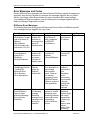
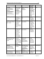
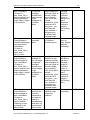
Error Messages and Codes ....................................................................................... 53
Server-Specific Error Codes ...................................................................................... 57
FINS Response Codes .............................................................................................. 57
Reference ...................................................................................................................... 62
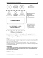
DAServer Architecture ............................................................................................... 62
DAServers .............................................................................................................. 62
Plug-ins................................................................................................................... 63
Component Environments ......................................................................................... 64
Omron Ethernet DAServer Ver 1.x User Manual Rev 1.3
17014m13
Klinkmann Automation Omron Ethernet DAServer
1
Before You Begin
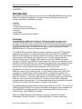
About This User Guide
This user’s guide describes the user interface and functions of the KLINKMANN OMRON
Ethernet Direct DAServer. It also provides you with the step-by-step procedures on how
to configure and use the OMRON Ethernet Direct DAServer after it is installed.
The OMRON Ethernet Direct DAServer user’s guide is organized in the following fashion:
• Contents
• Introduction: contains overview information about the OMRON Ethernet Direct
DAServer and the environment in which it works.
• Configuration: contains a detailed description of the user interface elements of this
DAServer in addition to its functionality.
• Item Names: describes the item naming conventions for targeted devices.
• Troubleshooting: provides information about error messages, codes, and conditions
displayed by the OMRON Ethernet Direct DAServer.
• Reference: describes the DAServer architecture in general.
• Index
You can view this document on-line or you can print it, in part or whole, by using the
Adobe Acrobat Reader’s print facility.
Omron Ethernet DAServer Ver 1.x User Manual Rev 1.3
17014m13
Klinkmann Automation Omron Ethernet DAServer
2
CHAPTER 1
Introduction
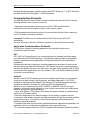
This chapter provides you with an overview of the KLINKMANN OMRON Ethernet Direct
DAServer, including the application- and bus-level communications protocols, item
naming conventions and DAServer features.
Contents
• Overview
• Communications Protocols
• Accessing Items via the DAServer
• Features
• Demo Mode
• Network Environment and Conditions
Overview
The KLINKMANN OMRON Ethernet Direct DAServer (hereafter referred to as the
“OMRON Ethernet DAServer” or “DAServer” or “DASOmronEth” throughout the
remainder of this user’s guide) is a Microsoft ® Windows ® application program that acts
as a FINS message communications protocol server. It allows other Windows application
programs access to data from OMRON PLCs (also referred to as devices) over the
OMRON Ethernet FA (Factory Automation) network.
The OMRON Ethernet Direct DAServer requires an Ethernet card and TCP/IP protocol
installed on the computer to communicate with the Ethernet network. The OMRON
Ethernet Direct DAServer can access to data from Controllers connected to the Ethernet
System directly (with Ethernet Unit installed) or from Controllers interconnected to
Ethernet System through SYSMAC LINK network or any other OMRON FA network
(through PC Gateway - an OMRON Controller which has multiple Communications Units
mounted, including the Ethernet Unit, and therefore that belongs to two networks and can
thus function as an interface between them). The OMRON Ethernet Direct DAServer
supports the Controller Memory Areas accessible by FINS commands.
No additions to Controller’s user program are needed if OMRON Ethernet Direct
DAServer is used in a poll (normal) mode, i.e. the DAServer sends read or write FINS
command to Controller and Controller responds with corresponding response. The
OMRON Ethernet Direct DAServer supports also the possibility to receive “unsolicited”
data from Controller – in this case some additions in Controller program are needed. The
DAServer “slave” mode can be established – at communication start-up DAServer
requests data one time and after it - only unsolicited data can be received from Controller.
At same time the writing of new values to Controller is still possible.
The OMRON Ethernet Direct DAServer can access to data from CS1/CJ1, CV-series and
C200HX/C200HG/C200HE PLCs (directly from Ethernet network or inter-networked from
other OMRON FA networks) as well as from C-series and CQM1 PLCs (only internetworked from other OMRON FA networks).
While the OMRON Ethernet Direct DAServer is primarily intended for use with
Wonderware InTouch ® (Version 7.11 Patch 02 and later), it may be used by any
Omron Ethernet DAServer Ver 1.x User Manual Rev 1.3
17014m13
Klinkmann Automation Omron Ethernet DAServer
3
Microsoft Windows program capable of acting as a DDE, SuiteLink ™ or OPC client that
can also coexist with FactorySuite ™ 2000 and greater.
Communication Protocols
The OMRON Ethernet Direct DAServer communicates with clients and PLCs using the
following different communications protocols:
• Application communications protocols such as OPC, DDE and SuiteLink to
communicate with clients located on either local or remote nodes.
• FINS message communications protocol to communicate with the Omron controllers
over FA (Factory Automation) networks.
Important! This DAServer is compliant with the OPC Data Access (DA) 2.05
specification.
For more information about the DAServer architecture, see the Reference section.
Application Communications Protocols
The DAServer utilizes the following application communications protocols to
communicate with the clients.
OPC
OPC (OLE for Process Control) is a non-proprietary set of standard interfaces based
upon Microsoft’s OLE/COM technology. This standard makes possible interoperability
between automation/control applications, field systems/devices and business/office
applications.
Avoiding the traditional requirement of software/application developers to write custom
drivers to exchange data with field devices, OPC defines a common, high-performance
interface that permits this work to be done once, and then easily reused by HMI, SCADA,
control and custom applications. Over the network, OPC uses DCOM (Distributed COM)
for remote communications.
SuiteLink
SuiteLink uses a TCP/IP-based protocol and is designed specifically to meet industrial
needs such as data integrity, high throughput, and easier diagnostics. This TCP/IP
standard is supported on Windows NT and Windows NT-technology-based operating
systems (for example, Windows NT, Windows 2000, and Windows XP).
SuiteLink is not a replacement for DDE, FastDDE, or NetDDE. The protocol used
between a client and a server depends on your network connections and configurations.
SuiteLink provides the following features:
• Value Time Quality (VTQ) places a time stamp and quality indicator on all data values
delivered to VTQ-aware clients.
• Extensive diagnostics of the data throughput, server loading, computer resource
consumption, and network transport are made accessible through the operating system’s
performance monitor. This feature is critical for the operation and maintenance of
distributed industrial networks.
• Consistent high data volumes can be maintained between applications regardless if the
applications are on a single node or distributed over a large node count.
• The network transport protocol is TCP/IP using Microsoft’s standard WinSock interface.
Omron Ethernet DAServer Ver 1.x User Manual Rev 1.3
17014m13
Klinkmann Automation Omron Ethernet DAServer
4
FastDDE
FastDDE provides a means of packing many proprietary Wonderware Dynamic Data
Exchange messages into a single Microsoft DDE message. This packing improves
efficiency and performance by reducing the total number of DDE transactions required
between a client and a server.
Although Wonderware's FastDDE has extended the usefulness of DDE for our industry,
this extension is being pushed to its performance constraints in distributed environments.
DDE
DDE is a communications protocol developed by Microsoft to allow applications in the
Windows environment to send/receive data and instructions to/from each other. It
implements a Client/Server relationship between two concurrently running applications.
The server application provides the data and accepts requests from any other application
interested in its data. Requesting applications are called clients. Some applications such
as InTouch and Microsoft Excel can simultaneously be both a client and a server.
NetDDE
NetDDE is a communications protocol that extends the standard DDE functionality to
include communications over local area networks and through serial ports. Network
extensions are available to allow DDE links between applications running on different
computers connected via networks or modems.
For example, NetDDE supports DDE between applications running on IBM-compatible
computers connected via LAN or modem, and DDE-aware applications running on nonIBM-compatible computers under operating environments such as VMS and UNIX.
FINS Message Communication
The FINS Messages system is developed by OMRON for its Factory Automation
networks. FINS Communications allow PLCs on these networks to be controlled by
reading and/or writing memory area data without the need to program these operations
into the controller’s user program.
Accessing Items via the DAServer
The method for accessing items through the DAServer depends on the communications
protocol being used.
OPC
In the case of OPC communications, the protocol addresses an element of data in a
conversation with six characteristics: node name, program name, group name, device
group, link name, and item name.
• The node name (required for remote access) and device group are optional.
• A fully qualified OPC Item name (ItemID) is composed of the link name and item name.
• All other characteristics are specified through separate DAServer means.
Omron Ethernet DAServer Ver 1.x User Manual Rev 1.3
17014m13
Klinkmann Automation Omron Ethernet DAServer
5
To access an OPC item, the OPC client needs to connect to the DAServer (either inprocess or out-of-process) and create an OPC group defining the data-acquisition
properties for the collection of items to be added. OPC groups
can be either public or private. Public OPC groups are shared across multiple clients,
whereas private OPC groups are local to a single client. Optionally, a device group, which
indicates the access path to the items for read/write, can
be specified from the DAServer.
The following briefly describes each characteristic of the OPC protocol:
• node name: Computer (host) name identifying a specific node on the network (for
Remote Access ONLY).
• program name: The registered OPC server name uniquely identifying a specific server
(ProgID). For this DAServer, the program name is ArchestrA.OmronEth.1.
• group name: The OPC group created from the client for organizing a collection of items
logically with the same data acquisition properties between the client and the server, such
as update rate.
• device group: Meaningful names configured in the DAServer under a specific controller
for the common custom attributes between the DAServer and the device, such as update
interval. If not specified from the client, the default device group using the global
configuration attribute values from the DAServer is assumed. Functionally, a device group
is equivalent to an access path (optional).
• link name: The set of hierarchy node names, representing the specific devices on a
communications path link from the hierarchy root to a specific controller as configured for
this DAServer under the DAServer Manager, separated by delimiters.
• item name: A specific data element, the leaf of the hierarchy tree of this DAServer,
within the specified group. For example, when using this DAServer, an item can be a
relay, timer, counter, register, and so on, in the controller.
DDE/SuiteLink
In the case of DDE/SuiteLink communications, the protocol addresses an element of data
in a conversation that uses a four-part naming convention that includes the node name,
application name, topic name, and item name. The fully qualified DDE/SuiteLink naming
convention includes all four parts, although the node name part (required for remote
access only) is optional. The following briefly describes each portion of this naming
convention:
• node name: Computer (host) name identifying a specific node on the network (for
Remote Access ONLY).
• application name: The name of the Windows program (this DAServer) that will be
accessing the data element. In the case of data coming from or going to the Modicon
devices via the DDE/SuiteLink PlugIn of this DAServer, the application name portion of
the address is DASOmronEth.
Omron Ethernet DAServer Ver 1.x User Manual Rev 1.3
17014m13
Klinkmann Automation Omron Ethernet DAServer
6
• topic name: Meaningful names are configured in the DAServer to identify specific
devices. These names are then used as the topic names in all conversations with that
device. For example, OmronPLC. Topic name maps to a device group defined in the
DAServer.
Note: You can define multiple device-group (topic) names for the same device (PLC) to
poll different points at different rates.
• item name: A specific data element within the specified topic. For example, when using
this DAServer, an item can be a relay, timer, counter, register, and so on, in the PLC.
Note: The term "point" is used interchangeably with the term "item" in this user's guide.
For more information on item/point names, see the Item Names section of this user's
guide.
Features
The KLINKMANN OMRON Ethernet Direct DAServer provides the following features:
• The ability to communicate over multiple application-level protocols at the same time.
• The ability to add new application-level protocols on the fly.
• The ability to be configured remotely.
• New, robust diagnostic abilities.
For more in-depth information on the DAServer architecture, see the Reference section.
Demo Mode
Demo Mode allows you to test the functionality of the OMRON Ethernet Direct DAServer
(with all features enabled) for 60 minutes. After that time, you must install HASP key.
The HASP key is needed for full time running of OMRON Ethernet Direct DAServer. The
HASP Driver setup is performed during the DAServer setup. Without HASP Driver
installed the OMRON Ethernet Direct DAServer will run supporting all features only 60
minutes after which the server stops updating read/write on all device items and reject the
addition of any new items.
Clients continue to function normally (for example, you can still add or remove an item,
but its value is not updated).
Note: The $SYS$Licensed system item value with OMRON Ethernet Direct DAServer is
not relevant.
Omron Ethernet DAServer Ver 1.x User Manual Rev 1.3
17014m13
Klinkmann Automation Omron Ethernet DAServer
7
CHAPTER 2
Before starting the OMRON Ethernet DAServer
This chapter contains instructions how to configure OMRON PLCs to be accessible by
Omron Ethernet DAServer in OMRON Ethernet FA network.
Configuration example deals with local network. If data are to be accessed from remote
networks then Relay Network Tables must be additionally configured in the PLC.
Contents
• Preparing the Hardware to be Used with Omron Ethernet DAServer
• Ethernet Unit Configuration Example for CS1 PLC
• Example program for sending “unsolicited” data from PLC
Preparing the Hardware to be used with OMRON Ethernet
DAServer
The Omron Ethernet DAServer requires an Ethernet card and TCP/IP protocol supporting
Windows Sockets interface to be installed on the computer to communicate with the
OMRON PLCs over the Ethernet network.
Each connected OMRON Controller (with Ethernet Unit installed) must be configured to
allow it to function as a node on the Ethernet network. This setup can be done by
switches on the module and/or appropriate programming software.
The OMRON C200HX/C200HG/C200HE PLCs (except CPU11), CV-series PLCs, CS1
PLCs as well as CJ1 PLCs can be used as nodes on Ethernet network. The
C200HX/C200HG/C200HE PLCs must be supplied with communication module:
C200HW-PCS01-EV1 Ethernet Set or C200HW-PCU01 PC Card Unit supplied with the
Ethernet PC Card (e.g. Kingston T.C. EtheRxEthernet PC Card models: KNE-PCM/M –
for coaxial and twisted pair connection, KNE-PCM/T – for twisted pair connection).
The CS1-series PLCs must be supplied with CS1W-ETN01 Ethernet Unit.
The CJ1-series PLCs must be supplied with CJ1W-ETN11 Ethernet Unit.
The CV-series PLCs must be supplied with CV500-ETN01 communication module.
The Ethernet PC Card installed in the C200HW-PCU01 PC Card Unit in the
C200HX/C200HG/C200HE PLC is configured by software supplied with communication
hardware.
Node number and Unit number of CV500-ETN01 (in CV-series PLC) is set by rotary
switches on the module. Software (CVSS software, SYSWIN or CX-Programmer) is used
to configure IP Address, Routing tables and IP Address tables.
Node number and Unit number of CS1W-ETN01 Ethernet Unit (in CS1-series PLC) is set
by rotary switches on the front side of module. Local IP Address is set by switches SW1,
SW2, ..., SW8 on the back side of module. Software (CX-Programmer) is used to
configure Routing tables and IP Address tables.
Node number and Unit number of CJ1W-ETN11 Ethernet Unit (in CJ1-series PLC) is set
by rotary switches on the front side of module. Software (CX-Programmer) is used to
configure Routing tables, local IP Address and IP Address tables.
Omron Ethernet DAServer Ver 1.x User Manual Rev 1.3
17014m13
Klinkmann Automation Omron Ethernet DAServer
8
Configuration software tool, appropriate (and recommended) for all OMRON controllers is
OMRON CX-Programmer Windows Programing Software (see “OMRON CX-Programmer
Users Manual”) .
Ethernet Unit Configuration Example for CS1 PLC
Connect the computer to the PLC CPU unit with Host Link Cable. Install the CXProgrammer software.
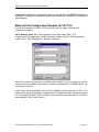
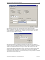
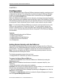
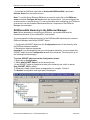
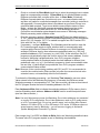
Set IP Address table. Start CX-Programmer (from Start menu: Start/.../CXProgrammer/CX-Programmer). Create new project (option "New" in CX-Programmer's
system menu). The "Change PLC" dialog box appears.
Enter PLC's name in the project (e.g. default name NewPLC1), PLC's model (e.g. CS1G)
and set the communication type used to access the configured PLC (SYSMAC WAY - for
serial communication).
Press "Work Online" pushbutton (or Ctrl+W) to establish communication to the PLC. (The
same can be done the following: in treeview (on CX-Programmer main window) select the
PLC (in example "NewPLC1(CS1G) Offline") and click the mouse right button. The PLC's
menu appears. Click "Work Online".)
Omron Ethernet DAServer Ver 1.x User Manual Rev 1.3
17014m13
Klinkmann Automation Omron Ethernet DAServer
9
When CX-Programmer establishes communication with PLC, select "Operating Mode"
(from PLC's menu) and set "Program" mode.
Note:
If you do not know (or have forgotten) the communication settings currently configured in
the PLC, the Auto Online feature can be useful – from CX-Programmer’s main menu
select “PLC/Auto Online/Auto Online” and CX-Programmer will search for all possible
settings until the proper ones are found; after that the current PLC program will be
automatically uploaded to CX-Programmer and it will go to online state with operating
mode set "Program" mode.
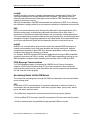
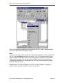
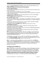
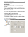
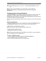
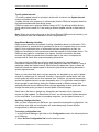
Double-click on "IO Table" in treeview. The "PLC IO Table - NewPLC1" dialog box
appears. Select "Options" and click "Transfer from the PLC":
Omron Ethernet DAServer Ver 1.x User Manual Rev 1.3
17014m13
Klinkmann Automation Omron Ethernet DAServer
10
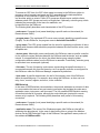
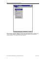
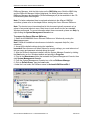
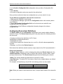
When IO Table is received, display the slot list under Main Rack (press "+" button in the
"PLC IO Table - NewPLC1" dialog box). Select "Ethernet Unit(ET)(0)" and press the
mouse right button. The Ethernet Unit menu appears:
Omron Ethernet DAServer Ver 1.x User Manual Rev 1.3
17014m13
Klinkmann Automation Omron Ethernet DAServer
11
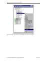
Click "Unit Setup". The "Ethernet Unit CPU Bus Unit" dialog box appears:
Omron Ethernet DAServer Ver 1.x User Manual Rev 1.3
17014m13
Klinkmann Automation Omron Ethernet DAServer
12
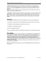
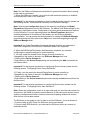
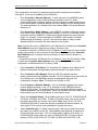
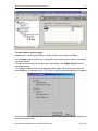
Enter Address Conversion type, FINS UDP port number and Sub-net Mask.
Edit the IP Address Table: the computer where Omron Ethernet DAServer is running
must be added to the IP Address Table. To add it, press "Insert" button. The "Insert
Router's IP Address" dialog box appears:
Enter the Node Number (in example 55) matching to the last octet in IP Address of
computer where Omron Ethernet DAServer is running. Enter the IP Address of computer
where Omron Ethernet DAServer is running (in example 195.2.103.55). Press "Ok".
Insert the Node Number and IP Address of PLC. (In case of CS1-series PLCs the Node
Number must match with settings on the rotary switch on the front side of Ethernet
communication unit, IP Address – must match with settings of rotary switches on the back
side of Ethernet communication unit).
Omron Ethernet DAServer Ver 1.x User Manual Rev 1.3
17014m13
Klinkmann Automation Omron Ethernet DAServer
13
To complete the configuration: from the "Ethernet Unit CPU Bus Unit" (or from the "PLC
IO Table - NewPLC1") dialog box select "Options" and click "Transfer to PLC".
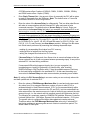
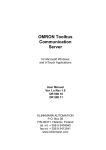
Example program for sending “unsolicited” data from PLC
The PLC example program presented in Plcprg.cxp project incorporates the SEND(090)
instruction for transferring unsolicited data from PLC to the OMRON ETHERNET
DAServer (for programming details see SYSMAC CS1 Series CS1W-ETN01 Ethernet
Unit OPERATION MANUAL, section 5).
The program transfers 10 words of data from D10 (notation in ladder diagram - D00010)
from the PLC to the OMRON ETHERNET Server (into address D500). The computer
where Omron Ethernet DAServer is running has the IP Address: 195.2.103.55 and the
destination node number is assigned to 55 (37 in hex).
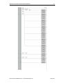
Comments on example program ladder diagram:
(0) Periodically (once per second) the execution condition flag CIO 000000 turns ON.
Note: There can be different logic to turn ON execution condition flag in real
application.
(1) If the Communication Port Enabled Flag for port 7 is ON, the send execution program
will start when the execution condition flag CIO 000000 turns ON. Input CIO 120000
remains ON from the start of SEND execution until completion. Note: The CS1-series
CPU Unit’s Communication Port Enabled Flags are allocated the following way - in Word
A202: Bit 0 – is associated with Port 0, Bit 1 – is associated with Port 1, … , Bit 7 – is
associated with Port 7. Bit’s status OFF - means execution enabled, ON – means
execution disabled.
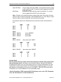
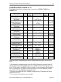
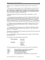
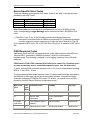
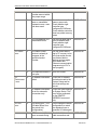
(2) Control data (D0, D1, … D4) creation
Word
D0000
D0001
Contents
00 0A
00 00
D0002
37 00
D0003
87 05
D0004
00 64
Meaning
Number of send words = 10
Destination network number = 0 (local
network)
Destination node number = 55 (37 hex)
Destination unit address = 0
Response not required
Communication port No = 7
Number of retries = 5
Response monitor time = 10 s
Ten words with data from D10 from PLC are sent to D500 onwards on the local network,
node number 55, unit address 0 (the computer where Omron Ethernet DAServer is
running) – to receive all these data the items with addresses D500…D509 can be
correspondingly activated for Omron Ethernet DAServer.
Important! With current example program an application will periodically toggle values of
areas D500…D509 with values of areas D10…D19. This is because of DAServer time-
Omron Ethernet DAServer Ver 1.x User Manual Rev 1.3
17014m13
Klinkmann Automation Omron Ethernet DAServer
14
by-time poll area D500…D509 and time-by-time gets unsolicited command assigning to
items D500…D509 values of PLCs D10…D19 area. Even if corresponding Controller is
configured to be processed in slave mode – at communication start-up DAServer process
several general data reading commands, accessing toggle effect.
If your application does not need toggling effect – configure SEND(090) instruction so,
that source area matches to destination area. In example – source data must start at
D500, if data are sent to D500 onwards.
(3) Reset the Input creation.
(4) Turn ON error information flag CIO 001300 if error happens. In this case CIO 001300
is not mandatory; any other flag may be used. Note: The CS1-series CPU Unit’s
Communication Port Error Flags are allocated the following - in Word A219: Bit 0 – is
associated with Port 0, Bit 1 – is associated with Port 1, … , Bit 7 – is associated with
Port 7. Bit’s status OFF - means Normal completion, ON – means Abnormal completion.
(5) The end of example program.
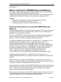
The example program ladder diagram is following:
Omron Ethernet DAServer Ver 1.x User Manual Rev 1.3
17014m13
Klinkmann Automation Omron Ethernet DAServer
Omron Ethernet DAServer Ver 1.x User Manual Rev 1.3
15
17014m13
Klinkmann Automation Omron Ethernet DAServer
16
CHAPTER 3
Configuration
Once the KLINKMANN Omron Ethernet DAServer has been installed, a small amount of
configuration is required. This configuration is performed using the DAServer Manager
hosted in the System Management Console after it is started through the Programs
menu of the Windows Start button.
Before the DAServer is activated, the device hierarchy, simulating the physical hardware
layout, must first be built to establish communications to each of the controllers. Once the
Omron Ethernet hierarchy has been built, the respective devices for communications can
be configured. Finally, the desired Device Groups for each controller may be created.
Note: To run the Omron Ethernet DAServer as a service, use the context menu on the
DAServer name and select “Configure As Service”. You can configure it as an auto
service or manual service. For more information about configuring your DAServer as a
service, see the “Activation/Deactivation/Service Component” of the DAServer Manager
documentation.
Contents
• Getting Started Quickly with the DAServer
• Configuring the DAServer
• Configuring Device Group Definitions
• Configuring Device Item Definitions
• Hot Configuration
Getting Started Quickly with the DAServer
This section briefly describes the procedures required to prepare the Omron Ethernet
DAServer for use. Detailed descriptions of each step can be found in later sections of this
documentation. This section is intended for people who are familiar with DAServers.
Note: If you are not familiar with DAServer functionality, please proceed to the moredetailed procedures following this section.
The following procedures assume that you have:
• Configured the PLC with which you wish to communicate.
To prepare the Omron Ethernet DAServer
1. Install the KLINKMANN Omron Ethernet DAServer on Windows by running the
Setup.exe program.
Note: DAServer installation instructions are included in a separate Help file (.chm
extension).
• Accept all the default settings during the installation.
Important! Since there are no default values for security settings, you must take note of
the user name and password selected during the install.
2. Start the Wonderware DAServer Manager by selecting the Programs menu from the
Start button on the taskbar.
3. Navigate to the Wonderware folder that contains the System Management Console,
then click System Management Console.
Omron Ethernet DAServer Ver 1.x User Manual Rev 1.3
17014m13
Klinkmann Automation Omron Ethernet DAServer
17
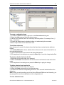
4. From the System Management Console, find the Omron Ethernet DAServer in the
DAServer Manager tree, the location in which it is installed.
• Under the Local branch node, the name of the DAServer is
Archestra.DASOmronEth.1.
• See the DAServer Manager documentation for general information about working in this
snap-in environment.
5. The new Omron Ethernet DAServer must now be configured.
• Before proceeding, determine the hierarchical structure of the network/PLC environment
to which you plan to connect.
6. Right-click the Configuration object that already exists in the tree, and select Add
SOCKET Object from the shortcut menu.
• A new SOCKET object is created as a node in the hierarchy tree and is named
New_SOCKET_000 by default.
• In this step, in addition to Step 7, the hierarchy entry is added in "edit mode," providing a
convenient place for you to appropriately describe components of your specific hardware
environment.
• If you do not rename the object at this time, a numeric sequencing system is applied.
• Any hierarchy entry can be renamed at a later time.
7. Right-click on the new SOCKET object, and from the shortcut menu, select
Add CONTROLLER Object
8. Configure the respective device objects, created in the preceding steps, with the
appropriate parameter values, if applicable.
• Optionally, the desired device groups can be created under the Device Groups tabbed
page with each of the Controller objects.
• Desired device items can also be optionally created under the Device Items tabbed
page with each of the Controller objects.
Note: The hierarchy entry is added in the "edit mode," providing a convenient place for
you to appropriately describe components of your specific hardware environment. Both
hierarchy node name and device group name are numerically sequenced by default.
They can be renamed at any time.
The DAServer is now ready for use. In order to use the DAServer, you must activate it
from the DAServer Manager using either the shortcut menu’s Activate Server command
from the Archestra.DASOmronEth.1 node, or from OPC Client.
Note: To run the Omron Ethernet DAServer as a service, right-click on the DAServer
name and select Configure As Service from the shortcut menu. You can configure it as
an auto service or manual service. For more information about configuring your DAServer
as a service, see the Activation/Deactivation/Service Component of the DAServer
Manager documentation.
Configuring the DAServer
Note: This DAServer is hosted by DAServer Manager, a Microsoft Management Console
(MMC) snap-in, which is a part of the ArchestrA System Management Console (SMC)
suite of utilities. Many high-level functions and user-interface elements of the DAServer
Manager are universal to all DAServers, and only the documentation for the DAServer
Manager contains descriptions of those universal functions/UI elements. Therefore,
reading the documentation for both the MMC and the DAServer Manager is critical to
understanding this user’s guide. To read the documentation about the MMC and
Omron Ethernet DAServer Ver 1.x User Manual Rev 1.3
17014m13
Klinkmann Automation Omron Ethernet DAServer
18
DAServer Manager, click the Help topics on the SMC Help menu. Both the MMC Help
and the DAServer Manager Help are displayed. An Adobe Acrobat version of the
DAServer Manager documentation (DAServerManager.pdf) is also available in the CDROM directory\User Docs\English.
Note: For better understand how to read and write data to the different OMRON
controllers, please refer to the chapter Before starting the Omron Ethernet DAServer.
Note: The shortcut menu items described in this document typically represent only a
subset of any actual shortcut menu. Most items in each shortcut menu are standard
Windows commands. For more information about those commands, please see Help, by
right-clicking the System Management Console icon.
To prepare the Omron Ethernet DAServer
1. Install the KLINKMANN Omron Ethernet DAServer on Windows by running the
Setup.exe program.
Note: DAServer installation instructions are included in a separate Help file (.chm
extension).
2. Accept all the default settings during the installation.
Important! Since there are no default values for security settings, you must take note of
the user name and password selected during the install.
3. After the DAServer has been installed, start the System Manager Console by clicking
the Start button on the Windows taskbar and pointing to Programs.
4. Point to the Wonderware folder that contains the System Management Console, then
click System Management Console.
5. From the System Management Console tree, click on DAServer Manager.
6. Click on Default Group, then the Local node.
• Under the Local node, the DAServer name is ArchestrA.DASOmronEth.1
Omron Ethernet DAServer Ver 1.x User Manual Rev 1.3
17014m13
Klinkmann Automation Omron Ethernet DAServer
19
Note: See the DAServer Manager documentation for general information about working
in this snap-in environment.
7. Before the DAServer is started, you must first build the device hierarchy to establish
communications to each of the controllers.
Important! For step-by-step procedures on how to build the device hierarchy, please see
the following section, "DASOmronEth Hierarchy in the DAServer Manager."
Note: Selecting the Configuration object of the hierarchy tree displays the Global
Parameters configuration view for this DAServer. The default Poke Mode settings for the
DAServer is Optimization mode. Configuration of all other global parameters as required
for this DAServer. For more information about the Global Parameters dialog box,
including descriptions of the different Poke Modes, see the DAServer Manager
documentation. You can access that documentation by clicking the DAServer Manager
icon and selecting the Help topics on the Help menu, and then navigating through the
DAServer Manager book.
Important! Any Global Parameters that appear dimmed are either not supported or
cannot be configured for this DAServer. Simulation Mode is not supported.
8. When the DASOmronEth hierarchy build has been completed, you can start
configuring the respective devices for communications.
9. You may create the desired Device Groups for each controller by:
• Navigating to the object of interest in the DAServer Manager tree view.
• Clicking on the Device Groups tab.
• Right-clicking in the Device Groups dialog box and selecting the Add command from
the shortcut menu.
Important! For step-by-step procedures on configuring Device Groups, please see the
following section, "Configuring Device Group Definitions."
10. Finally, you may create the desired Device Items for each controller by:
• Navigating to the object of interest in the DAServer Manager tree view.
• Clicking on the Device Items tab.
• Right-clicking in the Device Items dialog box and selecting the Add command from the
shortcut menu.
Important! For step-by-step procedures on configuring Device Items, please see the
following section, "Configuring Device Item Definitions."
Note: When any configuration view is in an open state and you open the same server the
second time, the DAServer locks the second instance of this same-server access for any
update or configuration activities. Access to this second opening instance will resume
after the first one has been closed.
The DAServer is now ready for use. In order to use the DAServer, you must activate it.
• If you are using an OPC Client, the DAServer can be auto-started.
• If you are using DDE/SuiteLink, you must start the DAServer either as a manual or
automatic service.
Omron Ethernet DAServer Ver 1.x User Manual Rev 1.3
17014m13
Klinkmann Automation Omron Ethernet DAServer
20
• To activate the DAServer, right-click on ArchestrA.DASOmronEth.1 and select
Activate Server from the shortcut menu.
Note: To run the Omron Ethernet DAServer as a service, right-click on the DAServer
name and select Configure As Service from the shortcut menu. You can configure it as
an auto service or manual service. For more information about configuring your DAServer
as a service, see the Activation/Deactivation/Service Component of the DAServer
Manager documentation.
DASOmronEth Hierarchy in the DAServer Manager
Note: Before attempting to configure your DAServer, you should determine the
hierarchical structure of your network/PLC environment.
The server-specific configuration portion of the DASOmronEth hierarchy tree under the
DAServer Manager starts at the SOCKET object.
1. Configure the SOCKET object from the Configuration branch of the hierarchy after
the DAServer has been installed.
2. Rename this object as appropriate.
Important! If you subsequently clear your configuration hierarchy, you must create this
SOCKET object from the Configuration branch of the hierarchy. From this point, all of
the following instructions apply.
To create SOCKET objects from the Configuration branch
1. Right-click on Configuration.
2. Select Add SOCKET Object from the shortcut menu.
• A new SOCKET object is created as a node in the hierarchy tree, and it is named
New_SOCKET_000 by default.
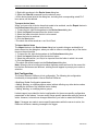
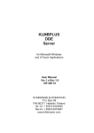
3. Rename the newly created object as appropriate, for example, “Socket1”.
The Socket1 configuration view (right pane) is displayed.
Omron Ethernet DAServer Ver 1.x User Manual Rev 1.3
17014m13
Klinkmann Automation Omron Ethernet DAServer
21
Enter/modify SOCKET parameters.
Host Name (IP Addr.)
Enter the Computer’s Internet Address (IP Address) if it has more than one. If there is
only one Internet Address for computer then you can use default address 0.0.0.0.
Port Number
Enter the UDP Port Number used for communication with OMRON Controllers. The Port
Number must match with Port Number configured in connected OMRON Controllers!
(OMRON Controllers send responses to Port number, configured in PLC, even if request
is received from different Port).
Note: The default port number is 9600.
From the SOCKET branch of the DAServer hierarchy, the CONTROLLER objects can be
created. CONTROLLER represents the logical endpoint to the hardware hierarchy.
To add CONTROLLER to your Omron Ethernet hierarchy
1. Right-click on the SOCKET branch.
2. Select Add CONTROLLER Object from the shortcut menu. It is named
“New_Controller_000” by default.
3. Rename it as appropriate, e.g. to “CS1” as used in following explanation – this new
CONTROLLER object name now will be used in the name of “Parameters” configuration
view.
The “Parameters” configuration view is displayed:
Omron Ethernet DAServer Ver 1.x User Manual Rev 1.3
17014m13
Klinkmann Automation Omron Ethernet DAServer
22
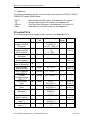
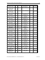
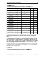
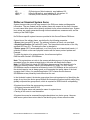
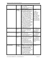
This configuration view has 15 parameters (configuration requires proven network
information, it can not be validated by the DAServer):
•
Enter Controller’s Network Address - to each network in the OMRON system
can be assigned an unique network address between 0 and 127. When
communicating with a node on another (remote) network, the entered value must
be consistent with the network address (non-zero) assigned in the routing tables.
The network address of 0 indicates the local network. Note: The default Network
Address is 0.
•
Enter Controller’s Node Address - each OMRON Controller in Ethernet network
must have its own unique node address between 1 and 126 (if Controller is internetworked via other OMRON FA network then Node Address can have different
range. For example, if inter-networked via SYSMAC LINK network, the Node
Address range is between 1 and 62. Care should be taken to select a node
address that will not conflict with other devices in the system.
Note: If destination node is OMRON PLC with Ethernet Unit installed then Controller
Node Address must be configured according to following rules:
- if automatic conversion of Ethernet Unit’s IP address is used (also the node number
setting rotary switch on the front panel of the Ethernet Unit is used) then Controller
Node Address must be equal with the fourth byte (octet) of local IP address of
Ethernet Unit;
- if automatic conversion of Ethernet Unit’s IP address is not used (IP Address Table
is used) then Controller Node Address must be equal with the Node number
configured in the Ethernet Unit’s IP Address Table.
•
Enter Controller’s IP Address. The Controller’s IP Address must match with IP
address configured at corresponding controller Ethernet Unit system setup.
•
Enter Controller’s Port Number. Enter the UDP Port Number used for
communications with this OMRON controller. The Port Number must much with the
Port Number set in the OMRON controller by appropriate Ethernet Unit
configuration software. Note: The default port number is 9600.
•
Enter Computer’s Network Address - the Local Network Address: the unique
network address between 1 and 127 is assigned to each OMRON Ethernet
network in the system. The entered value must be consistent with the network
address assigned in the routing tables. When communicate only with nodes in the
local network, you can set this Address to zero (default value).
•
Select the Controller Series. The available series are: CS1/CJ1, C200HX/HG/HE,
CV-series, C/CPM2X and CQM1. To select Controller Series, click on the combo
box button and make your choice from the list. Note: Only PLCs of CS1/CJ1,
C200HX/HG/HE and CV series are directly accessible in Ethernet network. All
other series PLCs must be inter-networked to get data from them.
•
Select Controller type. To select Controller type, click on the combo box button
and make your choice from the list. The available types depends on selection in
Controller Series combo box: CS1/CJ1 series offers 2 options (CS1 and CJ1),
C200HX/HG/HE series offers one option (C200HX/HG/HE), CV-series offers 5
options (CV500, CVM1-CPU01-E, CV1000, CV2000 and CVM1-CPU11-E),
Omron Ethernet DAServer Ver 1.x User Manual Rev 1.3
17014m13
Klinkmann Automation Omron Ethernet DAServer
23
C/CPM2x series offers 5 options (C200HS, C200H, C1000H, C2000H, CPM2x)
and CQM1 series offers 1 option (CQM1).
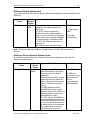
•
Enter Reply Timeout field - the amount of time (in seconds) the PLC will be given
to reply to commands from the DAServer. Note: The default value of 3 seconds
should be sufficient for most configurations.
•
Enter the value of the Access Delay (in milliseconds). This is a delay what Server
will make in communication with the selected PLC after each read or write
command execution. The default value of Access Delay is 0 (zero). Enter nonzero value in the Access Delay field only if you consider, that selected PLC is not
fast enough to correctly react to the Server's frequently sent requests.
The main timing problems for PLC can cause the writing of separate Bit status into
Word areas (for C200HX/C200HG/C200HE and CQM1 PLCs - into IR, LR, HR,
AR, DM and EM areas; for CV-series PLCs - into CIO, G, A, D, E, EA…EH areas;
for C/CPM2x PLCs - into IR, LR, HR, AR and DM areas; for CS1/CJ1 PLCs - into
CIO, W, H, A, D, and E areas; (see Item Names section). Writing of the Bit status
into Word area is performed by executing the following sequential steps:
- reading of corresponding Word value from PLC memory,
- setting a Bit to be written into the Word value,
- writing the changed Word value into PLC memory.
If Access Delay is 0 milliseconds, then Server tries to execute all steps as fast as
Omron network can do it (with no pauses between processing steps). It can put the
selected PLC into hard timing conditions.
If unsuccessful Bit writing happens time by time (you can recognize it by
investigating error logging in ArchestrA Log Viewer utility, after checking
DASProtFail flag in Log Flag Editor utility) - then the possible reason of fault may
be the hard timing conditions in the accessed PLC. In this case the setting nonzero value for Access Delay can make communication processing more reliable.
Note: By setting the PLC Access Delay to non-zero value you can seriously reduce the
real data update rate for selected PLC.
•
Enter the values of FINS Message Maximum Size for read and write commands.
Any value from 16 to prompted maximum number of bytes is valid if PLC is
accessed directly in local Ethernet network. If PLC is not accessed directly within
local network (the network common to the PC and PLC), but inter-networked from
other network then the maximum amount of data is limited by any network the data
passes through, i.e. the network with the smallest capacity will determine the limit.
The following is a maximum capacity of OMRON FA networks: Ethernet, Controller
Link and Sysmac Net - 1986 bytes; Sysmac Link and Serial networks – 512 bytes.
The greater value is configured the faster data update rate can be achieved.
Therefore reduce the FINS Message Maximum Size value only if selected PLC
has timing problems to process great amount of data in a short time period. The
default value is 1986 bytes.
Omron Ethernet DAServer Ver 1.x User Manual Rev 1.3
17014m13
Klinkmann Automation Omron Ethernet DAServer
24
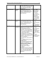
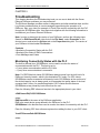
Check or uncheck the Slave Mode check box to select the principles how to obtain
data from corresponding controller. If Slave Mode is not checked (Master mode) –
DAServer polls data from controller all the time. In Slave Mode (if checked) DAServer requests data from Controller only once – at communication start-up and then only waits for unsolicited messages from controller (writing to controller is
still supported). Communication status is considered as good even if there is no
unsolicited data received. To get more reliable communication status in Slave
Mode – activate the Watchdog message processing (details see later in this
chapter) or time-by-time write values to PLC. With Watchdog activated –
Controller’s communication status depends on success of Watchdog messages.
Default processing mode is Master mode.
•
Enter the necessary setting in Gateway Count (GCT) field (the default setting is
2). GCT setting specifies the number of allowed bridge passes in FINS commands
sent to PLC; for example, GCT=7 is needed to support new CS/CJ-series CPU
Units with Unit Ver. 2.0 or higher.
•
If necessary – configure Watchdog. The Watchdog would be useful in case the
PLC internal program needs to check, whether there is communication with
computer where Omron Ethernet DAServer is runnung or not. With Watchdog
activated, DAServer time-by-time writes some predefined value (e.g. 255) into
predefined address in PLC’s memory (e.g. into D100). At the same time the PLC
program must periodically check the current value in this memory address. If value
is equal to Watchdog’s predefined value, then PLC’s program considers
communication Status as Good and resets the check address to different (nonpredefined) value, e.g. to 0. (It will allow to program to check communication state
the next time.) If value differs from predefined, then PLC’s program considers
communication Status as Bad.
Note: Because of time synchronizing problems with PLC and PC it is recommended to
consider the communication Status as Bad only after few consecutive test value
mismatch cases, not immediately after the first mismatch.
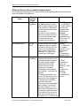
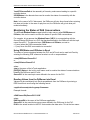
•
To activate the Watchdog processing - set Watchdog Time Interval to non-zero value.
Value entered in this field indicates the frequency (in seconds) the DAServer sends
Watchdog message to corresponding PLC. This value must be a bit less as time interval
the PLC program checks the value in watchdog address in the PLC.
Enter Address to Write field to indicate the watchdog address in PLCs memory that is
used as Watchdog check address. Address to Write must be a valid item/point name
(see Item Names section.)
Note: Use only Word memory areas for Watchdog. Do not take addresses not presented
on current PLC configuration. Do not take addresses, used as PLC system areas
or in PLC’s program logic. Do not use specific areas, such as Step Area Present
Values in CV-series PLCs, or IR or DR areas in CS1-series. If DAServer does not
accept memory area for Watchdog – you will see error logging in ArchestrA
System Management Console’s Log Viewer.
Enter integer from 0 to 65535 into Value to Write field to set Watchdog predefined value.
The same value PLC program expects to see in Watchdog check address.
Omron Ethernet DAServer Ver 1.x User Manual Rev 1.3
17014m13
Klinkmann Automation Omron Ethernet DAServer
25
Note: Default Watchdog state is “non-active”, i.e. Watchdog Time Interval is equal to
zero.
Note: In order to use the DAServer, you must activate it. See the DAServer
Manager documentation for information about how to activate and deactivate
the DAServer.
Configuring Device Group Definitions
The Device Groups tab in the DAServer Manager user interface is used to create a new
device group or modify or delete existing device group definitions for an object. For
DDE/SuiteLink communications, one or more device group definitions must exist for each
PLC that the DAServer will communicate with.
Each device group (topic) definition should contain a unique name for the PLC associated
with it.
Device Group Definitions
The Device Groups dialog box, which is displayed by clicking the Device Groups tab in
the Parameters configuration view, is used to perform the following activities:
• Adding, defining, and deleting device groups.
Note: When you add a new device group, enter a unique name.
• Configuring default update intervals.
• Editing update intervals for the objects.
Note: When you select another part of the DAServer tree hierarchy, you are prompted to
save the modifications to the configuration set.
To create or add device groups
1. To create or add device groups, right-click in the Device Groups box.
2. Select the Add command from the shortcut menu.
• When you add a new device group, enter a unique name.
Omron Ethernet DAServer Ver 1.x User Manual Rev 1.3
17014m13
Klinkmann Automation Omron Ethernet DAServer
26
To make edits on device groups
Make edits on a device group name or update interval for an object as follows:
• In the Name column, double-click or press F2 on the device group’s name to be edited
and make the edit.
• Double-click on the device group’s value to be edited in the Update Interval column,
and make the edit.
• To configure additional Device groups parameters right-click device group name and
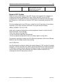
select Edit from the shortcut menu. The Device Group Parameters dialog box will appear:
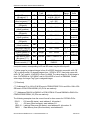
The Device Group parameters dialog can be used to configure preferred Read mode and
Write optimization mode.
Omron Ethernet DAServer Ver 1.x User Manual Rev 1.3
17014m13
Klinkmann Automation Omron Ethernet DAServer
27
If Memory Area Read is checked (default setting), then Server uses Memory Area Read
FINS commands and maximum (Read FINS Message Maximum Size – 14) / 2
consecutive words can be read from this Controller by one read command.
If Multiple Memory Area Read is checked then Server uses Multiple Memory Area Read
FINS commands and maximum 128 non-consecutive words (also from different memory
areas) can be read from this PLC by one read command.
Note: Even if Multiple Memory Area Read is configured - several memory areas are still
accessed by general read commands.
If Single Write option is checked, then for each new write value a separate write
message is created. The values in the PLC are changed by the DAServer in the same
sequence as they are changed in the user (client) application. With this option the data
update rate is low if application changes values very frequently, but sequence of value
changes are guaranteed.
If Last Msg Multiple Write option is checked, then the same message can be used for
the writing of new values into the consecutive memory addresses of the same memory
area (for example, into D0, D1, D2...). Up to 124 consecutive values can be included in
the same write command. The new value can be added only to the end of last write
message. Therefore some values may be written into the PLC memory simultaneously
even if the client application changes them step-by-step. With this option writing speed
can be seriously increased, and sequence of value changes are partly guaranteed
(several new values could be written into PLC memory simultaneously while application
change it step-by-step). For example, the client application sequentially changes the
values of following 248 items: D0, D1, ... , D247 and the values of following 248 items:
500R, 502R, ... , 994R. In this case the DAServer creates only four write messages to
write the new values for all the changed items. If the values of the same Items are
changed in the following sequence: DM0, 500R, DM1, 502R, DM2, ... then DAServer
creates a separate write message for each new write value.
If Any Msg Multiple Write option is checked, DAServer tries to include the new write
value into any of previously created messages ignoring the sequence of data changing
in the client application.
Important! With this option maximum writing speed is achieved, but this option is not
recommended if data changing sequence is important for PLC program!
To delete device groups
Deleting a device group from the list can be performed as follows:
1. Right-click on the device group to be deleted.
2. Select the Delete command from the shortcut menu.
Note: When you select another part of the Omron Ethernet DAServer tree hierarchy, you
are prompted to save the modifications to the configuration set.
To configure default update intervals
1. To configure a default update interval for the object, right-click in the Device Groups
box.
2. Select Config Default Update Interval from the shortcut menu.
Omron Ethernet DAServer Ver 1.x User Manual Rev 1.3
17014m13
Klinkmann Automation Omron Ethernet DAServer
28
To edit update intervals
• To edit the update interval for an object, double-click its value in the Update Interval
column and make the edit.
• Update Interval is the frequency (in milliseconds) that the DAServer acquires data from
the topics associated with that device group.
• Different topics can be polled at different rates in a PLC by defining multiple devicegroup names for the same PLC and setting a different Update Interval for each device
group.
Note: When you select another part of the Omron Ethernet DAServer tree hierarchy, you
are prompted to save the modifications to the configuration set.
Scan-Based Message Handling
DAServers are based on the concept of polling a hardware device for information. This
polling is driven by a need which is expressed in the form of requests from one or more
clients. Once a particular piece of information has been requested by a client, the
DAServer formulates its own request and sends that request to the hardware device. The
DAServer then waits for a response to its request. Once the information has been
received, the DAServer passes that information back to the client, and repeats the
process until all clients have ceased requesting information.
The rate at which the DAServer will poll a particular device for a specific piece of
information is defined in the device group (topic definition) inside the DAServer, using a
parameter called the Update Interval. When setting this parameter, there is always a
trade-off between the update speed of the device group and the resulting decrease in
system responsiveness.
Since you more than likely want very fast response, the temptation is to set the Update
Interval to a value close to 0 seconds. However, if every point is polled at this rate, the
entire system will suffer due to slow response time. Therefore, you should compromise,
and set the Update Interval to a more reasonable value. You could also create multiple
device groups for each device, setting the Update Interval to different values, then
assigning different items to different device groups depending on how quickly the values
change and how quickly you want to see an update of those changes.
Some items, like alarms, change very infrequently but because of their importance
require very fast updates. For those kinds of items, you should set the Update Interval at
a very small value. If you desire an immediate response, set the Update Interval at 1.
Archiving Configuration Sets
After you have configured your DAServer, you can archive that specific configuration. You
can archive more than one configuration set, and subsequently choose different
configurations for different purposes.
To archive configuration sets
1. In the DAServer Manager, right-click on the Configuration node in the hierarchy below
your DAServer.
2. Select Archive Configuration Set from the shortcut menu.
Omron Ethernet DAServer Ver 1.x User Manual Rev 1.3
17014m13
Klinkmann Automation Omron Ethernet DAServer
29
3. In the Archive Configuration Set configuration view, provide a Configuration Set
Name.
4. Click Archive.
• All current configuration values are saved to the archived set.
Once you have archived at least one configuration set, you can select it for use.
To use different configuration sets from the current one
1. Make sure the DAServer is not running.
2. In the DAServer Manager, right-click the Configuration node in the hierarchy below
your DAServer.
3. Select Use Another Configuration Set from the shortcut menu and click on a
configuration set in the sub-menu.
• All parameters in the DAServer configuration hierarchy change to the chosen
configuration set.
Configuring Device Item Definitions
The Device Items tab in the Parameters configuration view is used to define aliases to
actual PLC items. The Device Items dialog box is the place where the following activities
are performed:
• Creating new device item definitions for PLC items.
• Modifying the existing device items.
• Deleting device items.
• Archiving the created list of device items to a .csv file, a file with values separated by
commas.
• Bringing a .csv file into the Device Items tab.
Each device item definition should contain a unique name for the PLC associated with it.
Device Item Definitions
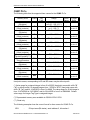
The Device Items dialog box, which is displayed by clicking the Device Items tab in the
CV500 Parameters configuration view, is used to add, clear all, rename, delete, import
and export device items. The Device Items dialog box has the following two columns:
• Name: This column defines the alias names to actual PLC items.
• Item Reference: The actual PLC item names, linked to the created aliases, are defined
in this column.
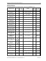
For example, for Data Memory Area D100, the following entries can be created.
Name
Item Reference
D100_Unsigned
D100_Signed
D100
D100S
Note: When you create or add a new device item, a unique name needs to be entered for
it.
Omron Ethernet DAServer Ver 1.x User Manual Rev 1.3
17014m13
Klinkmann Automation Omron Ethernet DAServer
30
To create or add device items
1. To create or add device items, right-click in the Device Items dialog box.
2. Select the Add command from the shortcut menu.
• A device item is created, and it is numerically named by default. For example, Item_0,
Item_1, and so on.
3. Change the default name by double-clicking on it and entering the new name.
• Enter a unique name for the new device item.
To add item references
Item references for each of the device items that have been created can be added as
follows:
1. In the Item Reference column, double-click on the area in the same horizontal line as
the selected device item.
2. Type in the actual PLC item name in the frame that appears.
3. Click anywhere in the dialog box or press the Enter key to have the change take effect.
To rename a device item from the list
1. Right-click on the device item to be renamed.
2. Select the Rename command from the shortcut menu and enter the new device item
name.
3. Click anywhere in the dialog box or press the Enter key to apply the change.
To delete a device item from the list
1. Right-click on the device item to be deleted.
2. Select the Delete command from the shortcut menu.
• The device item and its corresponding actual PLC item name will be deleted from the
dialog box.
Note: When you select another part of the Omron Ethernet DAServer tree hierarchy, you
are prompted to save the modifications to the configuration set.
To clear all device items
Omron Ethernet DAServer Ver 1.x User Manual Rev 1.3
17014m13
Klinkmann Automation Omron Ethernet DAServer
31
1. Right-click anywhere in the Device Items dialog box.
2. Select the Clear All command from the shortcut menu.
• All the device items listed in the dialog box, including their corresponding actual PLC
item names, will be deleted.
To export device items
When you have a list of device items that needs to be archived, use the Export feature in
the Device Items dialog box to archive the list.
1. To save the list, right-click anywhere in the Device Items dialog box.
2. Select the Export command from the shortcut menu.
3. Select the folder into which the list is to be saved.
4. Name the list to be archived.
5. Click the Save button.
• The whole list will be saved as a .csv file in Excel.
To import device items
The Import feature in the Device Items dialog box is used to bring an archived list of
device items into the dialog box, when you need to utilize or reconfigure any of the device
items on the archived list.
1. To import the list, right-click anywhere in the Device Items dialog box.
2. Select the Import command from the shortcut menu.
3. Select the archived list (.csv file) to be imported from the folder in which it is saved.
4. Click the Open button.
• The whole list will be brought into the Device Items dialog box.
Note: When the list to be imported contains duplicate names as found in the current list
but the Item References are different, a dialog box will appear to prompt you to make a
selection.
Hot Configuration
The Omron Ethernet DAServer is hot-configurable. The following hot-configuration
functionality is incorporated in Omron Ethernet DAServer:
• Modifying Global Configuration parameters.
• Adding, deleting, or modifying device nodes (without affecting any other device nodes,
excluding the children of the modified device nodes).
• Adding, deleting, or modifying device groups.
Limited support is provided for the hot configuration for the server-specific configuration
parameters in this release. You can modify server-specific parameters while the server is
active. However, to have those changes take effect, you have to restart the DAServer.
Note: If changes are made to server-specific parameters while the server is active, the
DAServer will issue a warning message to the logger.
Omron Ethernet DAServer Ver 1.x User Manual Rev 1.3
17014m13
Klinkmann Automation Omron Ethernet DAServer
32
CHAPTER 4
Item Names
The Omron Ethernet DAServer supports item/point names consistent with the point
naming conventions used by OMRON PLCs and programming software. The Server
supports almost all memory areas of the following OMRON PLC types: CS1, CJ1,
C200HX, C200HG, C200HE, CV-series, C-series, CPM2x and CQM1.
Contents
• Item Name General Format
• OMRON PLC’s Item Naming
• DAServer Standard System Items
• Generic OPC Syntax
Item Name General Format
In this section the general Item naming conventions used by OMRON Ethernet DAServer
are explained.
Each Integer, Discrete or Floating Point item generally may be described as:
PnS
Each item, representing bit in word, may be described as:
Pn:b (or Pn:bb or Pn.b or Pn.bb)
Each ASCII string item generally may be described as:
Pn-PhS
where:
n-
specifies the Memory area word/bit address of the specific word, flag or bit or
lowest-numbered address of ASCII string.
b (bb) - specifies the bit number in word (b can be 0…9 and bb can be 00…15). Number
of digits in bit item name with separator is not relevant (leading zeroes are not
necessary).
h-
Specifies the highest -numbered address of ASCII string.
P-
optionally used prefix, one, two or three characters before Memory area address,
and designates the type of Memory area.
S-
optionally used suffix - a letter after address, which is used to change the default
format of data. The following presents the OMRON Ethernet DAServer supported
data formats and suffixes, indicating corresponding format.
Unsigned/Signed Format
The server interprets 16-bit word in a PLC in 16-bit unsigned format (value limits 0
to 65535) or signed format (value limits -32768 to 32767). Unsigned quantities may
be read by one of two methods - by entering item name without suffix or appending
the suffix 'U' (or 'u') to the item name. For example, channel DM100 in a PLC
Omron Ethernet DAServer Ver 1.x User Manual Rev 1.3
17014m13
Klinkmann Automation Omron Ethernet DAServer
33
contains 8000 hex. In this case item name DM100 or DM100U would be displayed
in client as 32768. Signed quantities may be read from the same channel by
appending the suffix 'S' (or 's') to the item name. So, item name DM100S would be
displayed in client as -32768.
BCD Format
To read/write data using BCD format - append the suffix ‘B’ (or ‘b’) to the item
name, e.g. DM100B.
Long Format (Signed/BCD)
Two consecutive 16-bit words in a PLC can be interpreted as a 32-bit long integer.
It can be formatted as either signed (-2,147,483,648 to 2,147,483,648) or BCD (0
to 99,999,999). To read/write an item in signed long format - append the letter 'L'
(or 'l') to the item name. To read/write an item in BCD long format - append the
letter 'M' (or 'm') to the item name. For example, if DM100 contains 0234 hex and
DM101 contains 1356 hex, DM100L returns 324,403,764 and DM100M returns
13,560,234.
Note: Long format is not supported if Multiple Memory Area Read FINS commands
are used.
Floating Point Format (IEEE/BCD)
Two consecutive 16-bit words in a PLC can be interpreted as a single precision
38
floating point number. It is formatted as either IEEE (-3.402823 * 10 to 3.402823
38
-7
+7
* 10 ) or BCD (0.0000001 * 10 to 0.9999999 * 10 ). To read/write an item in
IEEE floating point format, append one of the following letters to the item name: 'F'
or 'f’. To read/write an item in BCD floating point format - append the letter 'G' (or
'g') to the item name. For example, if D100 contains 9620 hex and D101 contains
2436 hex in a CV500 PLC, D100F returns 3.959212 * 10-17 and D100G returns
0.4369620 * 102.
Floating point format is relevant only with items, indicating memory areas word
contents.
Note: IEEE format is NOT supported in the C-Series PLC family
Note: Floating point format is not supported if Multiple Memory Area Read FINS
commands are used.
ASCII Strings Format
Multiple consecutive 16-bit words (block size of 1 to 29) in a PLC can be
interpreted as a string of ASCII characters. The ASCII string is stored/retrieved
from the lowest-numbered address to the highest and from the high-order byte to
the low-order byte with each address. To define a range of words, use '-' (minus
sign) between the two address locations. For example, DM10-DM12 indicates
locations from DM10 to DM12. ASCII string characters can be specified to come
from the high-order byte, low-order byte, or both bytes of the words:
Low-order Byte
Only the low-order byte (LSB - least significant 8-bits) of each
word is used for read. To use this format, append the suffix 'E'
to the item name.
Omron Ethernet DAServer Ver 1.x User Manual Rev 1.3
17014m13
Klinkmann Automation Omron Ethernet DAServer
High-order Byte
Both Bytes
34
Only the high-order byte (MSB - most significant 8-bits) of each
word is used for read. To use this format, append the suffix 'D'
to the item name.
Both bytes of each word are used for read/write. To use this
format, append the suffix 'C' to the item name.
Note: All bytes in the specified memory range will be used. If the string is shorter
than the range of memory specified, it will be padded with '\0'. If the string is longer
than the range of memory specified, the string will be truncated.
For example, assume the following memory contents (numeric values shown in
hex):
DM10
DM11
DM12
MSB
41
43
45
LSB
42
44
46
"AB"
"CD"
"EF"
Read:
DM10 – DM12C
DM10 – DM11D
DM10 – DM12E
returns ABCDEF
returns AC
returns BDF
Write:
DM10 - DM12C
after written with "ABCD"
DM10
DM11
DM12
MSB
54
73
0
DM10 - DM12E
DM10
DM11
DM12
MSB
0
0
0
LSB
65
74
0
"AB"
"CD"
" "
after written with "ABCDE"
LSB
41
42
43
"A"
"B"
"C"
Imortant Note!
Do not operate with item names, which have addresses outside really existing PLC
data and memory area! It will lead to communication failures, because the DAServer
recognizes item name error only if item name goes out of range represented in the item
names table. Usually the information like following will be logged to logger if some item
with address in inaccessible memory area is used (MRC:11 and SRC:03 informs about
"Parameter error: the first address is in an inaccessible area")
<Socket.Controller>: FINS command 0101 failed (resp. error code 1103). Parameter
error: the first address is in inaccessible area.
Omron Ethernet DAServer Ver 1.x User Manual Rev 1.3
17014m13
Klinkmann Automation Omron Ethernet DAServer
35
CS1/CJ1 PLCs
The following table lists the supported item names for the CS1/CJ1 PLCs:
Memory Area
Prefix
Tag
Range
Value
Rang
Type
e
CIO Area
0, 1
Discrete CIO0:00...CIO6143:15
CIO
(Bit status)
or 0.00...6143.15
CIO Area
Integer
CIO0... CIO6143
(*)
CIO
(Word contents)
or 0...6143
Work Area
W0:00... W511:15
0, 1
Discrete
W
(Bit status)
Work Area
Integer
W0... W511
(*)
W
(Word contents)
Holding Area
H0:00... H511:15
0, 1
Discrete
H
(Bit status)
Holding Area
Integer
H0... H511
(*)
H
(Word contents)
Auxiliary Area
A0:00... A959:15
0, 1
Discrete
A
(Bit status) (**)
Auxiliary Area
Integer
A0... A959
(*)
A
(Word contents) (**)
Data Memory DM
Discrete
D0:00...D32767:15
0, 1
D
Area (Bit status)
Data Memory DM
Integer
D0...D32767
(*)
D
Area (Word cont.)
Expansion Data
Discrete
E0:00...E32767:15
0, 1
E
Memory (Bit status)
(***)
Expansion Data
Integer
E0... E32767
(*)
E
Memory
(Word cont.) (***)
Expansion Data
Discrete Ez0:00...Ez32767:15
0, 1
Ez
Memory (Bit status) (z = A
(****)
to M)
Expansion Data
Integer
Ez0... Ez32767
(*)
Ez
Memory
(z = A
(Word cont.) (****)
to M)
Timer Completion
T0... T4095
0, 1
Discrete
T
Flags (*****)
Discrete
Counter Completion
C0... C4095
0, 1
C
Flags (*****)
Integer
PVT0... PVT4095
(*)
Timer PVs
PVT
Counter PVs
PVC
Integer
PVC0... PVC4095
(*)
Index Registers
Data Registers
(******)
IR
DR
Long
Integer
IR0... IR15
DR0... DR15
(*)
(*)
Omron Ethernet DAServer Ver 1.x User Manual Rev 1.3
Format
Suffix
usbfgl
mdec
usbfgl
mdec
usbfgl
mdec
usbfgl
mdec
usbfgl
mdec
usbfgl
mdec
usbfgl
mdec
usbfgl
mdec
usbfgl
mdec
m
usb
17014m13
Klinkmann Automation Omron Ethernet DAServer
36
Item/point names, corresponding to CIO Area, may be without prefix.
(*) Value range for unsigned integer is from 0 to 65535 (item/point name with suffix "U"
("u") or without suffix), for signed integers from –32768 to 32767 (item/point name with
suffix "S" ("s")) and for 16-bit BCD is from 0 to 9999. The value range for long or 32-bit
integer is from -2147483648 to 2147483647 and for 32-bit BCD is from 0 to 99999999.
Default value range for Integer Tag Type is unsigned integer.
(**) Data cannot be written to addresses A000…A447 in the Auxiliary Area.
(***) Current bank only (Memory Area code 98 in Hex).
(****) Extended memory bank 0 to bank C (in Hex), up to 13 banks supported depending
on CPU type. The prefix Ez can be one of the following: EA, EB, EC, ED, EE, EF, EG,
EH, EI, EJ, EK, EL or EM. For read operations (both for Bit status and Words) and for
Word write operations the Memory Area codes A0…AC (in Hex) are used. For Bit writing
the Memory Area codes 20…2C (in Hex) are used.
(*****) Read only.
(******) Not supported on CJ1 controllers.
The following examples show the correct format for item names for CS1 and CJ1 PLCs:
CIO2:01
257
H62.10
D21
EA12
EC48.10
-
CIO area (Bit status), word address 2, bit number 1.
CIO Area (Word contents), word address 257
Holding Area (Bit), word address 62, bit number 10
Data Memory Area with word address 21
Extended Data Memory bank 0 word address 12
Extended Data Memory bank 2 word address 48, bit number 10
Omron Ethernet DAServer Ver 1.x User Manual Rev 1.3
17014m13
Klinkmann Automation Omron Ethernet DAServer
37
C200HX/C200HG/C200HE PLCs
The following table lists the supported item names for the C200HX, C200HG and
C200HE PLCs.
Memory Area
Prefix
Internal Relay Area 1, 2
Special Relay Area 1, 2
(Bit status)
Internal Relay Area 1, 2
Special Relay Area 1, 2
(Word contents)
Link Relay Area
(Bit status)
Link Relay Area
(Word contents)
Holding Relay Area
(Bit status)
Holding Relay Area
(Word contents)
Auxiliary Relay Area
(Bit status)
Auxiliary Relay Area
(Word contents)
IR
Tag
Type
Discrete
IR
Integer
LR
Discrete
IR0:00...IR511:15
or
0.00...511.15
IR0... IR511
or
0…511
LR0:00...LR63:15
LR
Integer
LR0... LR63
(*)
HR
Discrete
HR0:00... HR99:15
0, 1
HR
Integer
HR0... HR99
(*)
AR
Discrete
AR0:00... AR27:15
0, 1
AR
Integer
AR0... AR27
(*)
TC
Discrete
TC0... TC511
0, 1
PV
Integer
PV0... PV511
(*)
DM
Discrete
0, 1
DM
Integer
EM
Discrete
EM
Integer
DM0:00...
DM9999:15
DM0...
DM9999
EM0:00...
EM6143:15
EM0... EM6143
Timer/Counter Area
Completion Flag(****)
Timer/Counter Area
(PV)
Data Memory Area
(Bit status)(**)
Data Memory Area
(Word contents)(**)
Extended Data Memory
Area (Bit status)(***)
Extended Data Memory
Area Word contents(***)
Address Range
Value
Range
0, 1
Suffix
(*)
usbfgl
mdec
0, 1
(*)
usbfgl
mdec
usbfgl
mdec
usbfgl
mdec
usbfgl
mdec
0, 1
(*)
usbfgl
mdec
Item/point names, corresponding to Internal Relay/Special Relay Area may be without
prefix.
(*) Value range for unsigned integer is from 0 to 65535 (item/point name with suffix "U"
("u") or without suffix), for signed integers from –32768 to 32767 (item/point name with
suffix "S" ("s")) and for 16-bit BCD is from 0 to 9999. The value range for 32-bit integer is
from -2147483648 to 2147483647 and for 32-bit BCD is from 0 to 99999999. Default
value range for Integer Tag Type is unsigned integer.
(**) Memory area range DM7000…DM9999 is supported only if Expansion DM Area is
allocated on the PLC.
(***) Current bank only (Memory Area code 98).
Omron Ethernet DAServer Ver 1.x User Manual Rev 1.3
17014m13
Klinkmann Automation Omron Ethernet DAServer
38
(****) Read only
The following examples show the correct format for item names for C200HX, C200HG,
C200HE PLCs and SYSMAC Board:
IR2:01
257
LR62.10
DM21
-
Internal Relay Area (Bit status), word address 2, bit number 1.
Special Relay Area (Word contents), word address 257
Link Relay Area (Bit status), word address 62, bit number 10
Data Memory Area (Word contents), word address 21
CV-series PLCs
The following table lists the supported item names for the CV-series PLCs:
Memory Area
Prefix
Input/Output
register area CIO
(Bit status)
Input/Output
register area CIO
(Word contents)
Bus Link Area G
(Bit status)
Bus Link Area G
(Word contents)
Auxiliary Relay
area A (Bit status)
Auxiliary Relay
area A (Words)
Timer Completion
flags TIM (**)
Counter
Completion flags
CNT (**)
Timer Present
Value
Counter Present
Value
Data Memory area
(Bit status)
CIO
Data Memory area
(Word contents)
Transition Area
flags (**)
Step Area Flag
status (**)
Tag
Type
Discrete
Address Range
Value
Range
0, 1
Suffix
(*)
usbfgl
mdec
G
CIO0:00...
CIO2555:15
or 0.00... 2555.15
Integer
CIO0... CIO2555
or
0…2555
Discrete G0:00... G255:15
G
Integer
G0... G255
(*)
A
Discrete
A0:00... A511:15
0, 1
A
Integer
A0... A511
(*)
T
Discrete
T0...T1023(***)
0, 1
C
Discrete
C0... C1023(***)
0, 1
PVT
Integer
(*)
PVC
Integer
D
Discrete
D
Integer
PVT0...
PVT1023(***)
PVC0...
PVC1023(***)
D0:00…
D24575:15
(****)
D0...D24575(****)
TN
Discrete
ST
Integer
CIO
TN0...
TN1023(***)
ST0...ST1023
(***)
Omron Ethernet DAServer Ver 1.x User Manual Rev 1.3
0, 1
(*)
usbfgl
mdec
usbfgl
mdec
usbfgl
mdec
usbfgl
mdec
0, 1
(*)
usbfgl
mdec
0,1
0,1,2,3
17014m13
Klinkmann Automation Omron Ethernet DAServer
Step Timer
Present Value
Expansion area
Current bank
(Bit status)
Expansion area
Current bank
(Word contents)
Expansion area A
(Bit status)
Expansion area A
(Word contents)
Expansion area B
(Bit status)
Expansion area B
(Word contents)
Expansion area C
(Bit status)
Expansion area C
(Word contents)
Expansion area D
(Bit status)
Expansion area D
(Word contents)
Expansion area E
(Bit status)
Expansion area E
(Word contents)
Expansion area F
(Bit status)
Expansion area F
(Word contents)
Expansion area G
(Bit status)
Expansion area G
(Word contents)
Expansion area H
(Bit status)
Expansion area H
(Word contents)
Action Area Flag
(**)
Register Area
contents IR (***)
Register Area
contents DR (**)
PVS
Integer
E
39
Discrete
PVS0...
PVS1023(***)
E0:00...E32765:15
0, 1
E
Integer
E0...E32765
(*)
EA
Discrete
0, 1
EA
Integer
EB
Discrete
EB
Integer
EC
Discrete
EC
Integer
ED
Discrete
ED
Integer
EE
Discrete
EE
Integer
EF
Discrete
EF
Integer
EG
Discrete
EG
Integer
EH
Discrete
EH
Integer
AC
Discrete
IR
Integer
EA0:00...
EA32765:15
EA0...
EA32765
EB0:00...
EB32765:15
EB0...
EB32765
EC0:00...
EC32765:15
EC0...
EC32765
ED0:00...
ED32765:15
ED0...
ED32765
EE0:00...
EE32765:15
EE0...
EE32765
EF0:00...
EF32765:15
EF0...
EF32765
EG0:00...
EG32765:15
EG0...
EG32765
EH0:00...
EH32765:15
EH0...
EH32765
AC0…AC2047
(*****)
IR0...IR2
DR
Integer
DR0...DR2
(***)
Omron Ethernet DAServer Ver 1.x User Manual Rev 1.3
(*)
(*)
usbfgl
mdec
usbfgl
mdec
usbfgl
mdec
0, 1
(*)
usbfgl
mdec
0, 1
(*)
usbfgl
mdec
0, 1
(*)
usbfgl
mdec
0, 1
(*)
usbfgl
mdec
0, 1
(*)
usbfgl
mdec
0, 1
(*)
usbfgl
mdec
0, 1
(*)
usbfgl
mdec
0, 1
(*)
(*)
usbfgl
mdec
usbfgl
mdec
17014m13
Klinkmann Automation Omron Ethernet DAServer
40
Item/point names, corresponding to Input/Output register area CIO, may be without
prefix.
(*) Value range for unsigned integer is from 0 to 65535 (item/point name with suffix "U"
("u") or without suffix), for signed integers from 32768 to 32767 (item/point name with
suffix "S" ("s")) and for 16-bit BCD is from 0 to 9999. The value range for 32-bit integer is
from -2147483648 to 2147483647 and for 32-bit BCD is from 0 to 99999999. Default
value range for Integer Tag Type is unsigned integer.
(**) Read only. Note: with DR area item without suffix (or with suffixes u, s, b) are
Read/Write.
(***) Represented memory area ranges are for CV1000, CV2000 and CVM1-CPU11-E
(except Transition Area and Step Area Flag status) type controllers. For models CV500
and CVM1-CPU01-E (except Transition Area and Step Area Flag status) - accessible
memory area ranges are 0:00...511:15 for Discrete items and 0...511 - for Integer items.
Transition Area TN and Step Area Flag status area ST are not supported on CVM1 PLCs.
(****) Represented memory area ranges are for CV1000, CV2000 and CVM1-CPU11-E
type controllers. For models CV500 and CVM1-CPU01-E - accessible memory area
ranges are 0...8191.
(*****) Represented memory area ranges are for CV1000 and CV2000 type controllers
only. For model CV500 - accessible memory area ranges are 0...1023. With other CVseries PLCs – not supported.
Expansion area Current bank as well as Expansion areas (from EA to EH) is relevant only
with CV1000 and CV2000 PLCs.
Item names IR and DR are valid with following Omron PLC models: CV1000, CV2000
and CVM1-CPU11-E.
The configuration of the discrete data can be as follows:
Flag or Bit Status
0: Bit is OFF;
1: Bit is ON;
Step Status
0: INACTIVE;
1: HALT;
2: PAUSE;
3: EXECUTE;
The following examples show the correct format for item names for CV-series PLCs:
CIO1:15
211
TN200
ST0007
AC6
D3F
-
CIO area (Bit status), word address 1, bit number 15.
CIO area (Word contents), word address 211
Transition Area flag, address 200
Step Area Flag status, address 7
Action Area Flag status, address 6
real (floating point) item, value is taken from words D3 and D4.
Omron Ethernet DAServer Ver 1.x User Manual Rev 1.3
17014m13
Klinkmann Automation Omron Ethernet DAServer
41
C/CPM2x PLCs
The following table lists the supported item names for the C-series PLCs:
Memory Area
Prefix
CIO area
(Bit status)
CIO area
(Word contents)
Latching Relay area
(Bit status)
Latching Relay area
(Word contents)
Holding Relay area
(Bit status)
Holding Relay area
(Word contents)
Auxiliary Relay area
(Bit status)
Auxiliary Relay area
(Word contents)
Completion flags for
Timers/Counters(***)
Present Values for
Timers/Counters
Data Memory area
(Bit status)
Data Memory area
(Word contents)
IR
Tag
Type
Discrete
Range
Value
Range
0, 1
Format
Suffix
IR
Integer
LR
Discrete
IR0:00...IR511:15
or 0.00...511.15 (**)
IR0... IR511
or 0...511 (**)
LR0:00... LR63:15
(*)
usbfgl
mdec
LR
Integer
LR0... LR63
(*)
HR
Discrete
HR0:00... HR99:15
0, 1
HR
Integer
HR0... HR99
(*)
AR
Discrete
AR0:00... AR27:15
0, 1
AR
Integer
AR0... AR27
(*)
TC
Discrete
TC0... TC511
0, 1
PV
Integer
PV0... PV511
(*)
DM
Discrete
DM0:0...DM9999:15
0, 1
DM
Integer
DM0...
DM9999
(*)
0, 1
usbfgl
mdec
usbfgl
mdec
usbfgl
mdec
usbfgl
mdec
usbfgl
mdec
Item/point names, corresponding to Input/Output register area CIO, may be without
prefix.
(*) Value range for unsigned integer is from 0 to 65535 (item/point name with suffix "U"
("u") or without suffix), for signed integers from –32768 to 32767 (item/point name with
suffix "S" ("s")) and for 16-bit BCD is from 0 to 9999. The value range for 32-bit integer is
from -2147483648 to 2147483647 and for 32-bit BCD is from 0 to 99999999. Default
value range for Integer Tag Type is unsigned integer.
(**) Represented memory area range is for C200HS type controller. For models C200H,
C1000H and C2000H - accessible memory area ranges are 0:00...255:15 for Discrete
items and 000...255 for Integer items.
(***) Read only
The following table lists the supported item names for the CPM2x PLCs:
Omron Ethernet DAServer Ver 1.x User Manual Rev 1.3
17014m13
Klinkmann Automation Omron Ethernet DAServer
42
Memory Area
Prefix
IR & SR areas
(Bit status)(***)
IR & SR areas
(Word contents) (***)
Latching Relay area
(Bit status)
Latching Relay area
(Word contents)
Holding Relay area
(Bit status)
Holding Relay area
(Word contents)
Auxiliary Relay area
(Bit status)
Auxiliary Relay area
(Word contents)
Completion flags for
Timers/Counters(**)
Present Values for
Timers/Counters
Data Memory area
(Bit status) (****)
Data Memory area
(Word contents) (****)
IR
Tag
Type
Discrete
Range
Value
Range
0, 1
Format
Suffix
IR
Integer
LR
Discrete
IR0:00...IR255:15
or 0.00...255.15
IR0...IR255
or 0...255
LR0:00... LR15:15
(*)
usbfgl
mdec
LR
Integer
LR0... LR15
(*)
HR
Discrete
HR0:00... HR19:15
0, 1
HR
Integer
HR0... HR19
(*)
AR
Discrete
AR0:00... AR23:15
0, 1
AR
Integer
AR0... AR23
(*)
TC
Discrete
TC0... TC255
0, 1
PV
Integer
PV0... PV255
(*)
DM
Discrete
DM0:0...DM6655:15
0, 1
DM
Integer
DM0...
DM6655
(*)
0, 1
usbfgl
mdec
usbfgl
mdec
usbfgl
mdec
usbfgl
mdec
usbfgl
mdec
Item/point names, corresponding to IR and SR areas, may be without prefix.
(*) Value range for unsigned integer is from 0 to 65535 (item/point name with suffix "U"
("u") or without suffix), for signed integers from –32768 to 32767 (item/point name with
suffix "S" ("s")) and for 16-bit BCD is from 0 to 9999. The value range for 32-bit integer is
from -2147483648 to 2147483647 and for 32-bit BCD is from 0 to 99999999. Default
value range for Integer Tag Type is unsigned integer.
(**) Read only
(***) Addresses 50 to 199 in IR & SR area in CPM2A/CPM2C PLCs and 20 to 199 in IR &
SR area in CPM1/CPM1A/SRM1(-V2) PLCs are read only.
(****) Addresses DM1024 to DM6143 in CPM1/CPM1A PCs and DM2048 to DM6143 in
CPM2A/CPM2C/SRM1(-V2) PCs are read only.
The following examples show the correct format for item names for C/CPM2x PLCs:
IR2:01 211
LR62.10 DM21 -
CIO area (Bit status), word address 2, bit number 1.
CIO area (Word contents), word address 211.
Latching Relay area (Bit status), word address 62, bit number 10.
Data Memory area (Word contents), word address 21.
Omron Ethernet DAServer Ver 1.x User Manual Rev 1.3
17014m13
Klinkmann Automation Omron Ethernet DAServer
43
CQM1 PLCs
The following table lists the supported item names for the CQM1 PLCs:
Memory Area
Prefix
IR & SR area
(Bit status)
IR & SR area
(Word contents)
LR area
(Bit status)
LR area
(Word contents)
HR area
(Bit status)
HR area
(Word contents)
AR area
(Bit status)
AR area
(Word contents)
Completion flags for
Timers/Counters(***)
Present Values for
Timers/Counters
DM area
(Bit status)
DM area
(Word contents)
EM area
(Bit status)
EM area
(Word contents)
IR
Tag
Type
Discrete
Range
Value
Range
0, 1
Format
Suffix
IR
Integer
LR
Discrete
IR0:00...IR255:15
or 0.00... 255.15 (**)
IR0... IR255
or 0... 255 (**)
LR0:00... LR63:15
(*)
usbfgl
mdec
LR
Integer
LR0... LR63
(*)
HR
Discrete
HR0:00... HR99:15
0, 1
HR
Integer
HR0... HR99
(*)
AR
Discrete
AR0:00... AR27:15
0, 1
AR
Integer
AR0... AR27
(*)
TC
Discrete
TC0... TC511
0, 1
PV
Integer
PV0... PV511
(*)
DM
Discrete
DM0:0...DM6655:15
0, 1
DM
Integer
DM0...DM6655
(*)
EM
Discrete
EM0:0...EM6143:15
0, 1
EM
Integer
EM0...EM6143
(*)
0, 1
usbfgl
mdec
usbfgl
mdec
usbfgl
mdec
usbfgl
mdec
usbfgl
mdec
usbfgl
mdec
Item/point names, corresponding to IR and SR areas, may be without prefix.
(*) Value range for unsigned integer is from 0 to 65535 (item/point name with suffix "U"
("u") or without suffix), for signed integers from –32768 to 32767 (item/point name with
suffix "S" ("s")) and for 16-bit BCD is from 0 to 9999. The value range for 32-bit integer is
from -2147483648 to 2147483647 and for 32-bit BCD is from 0 to 99999999. Default
value range for Integer Tag Type is unsigned integer.
(**) Represented memory area available in CQM1H-CPU61 CPU.
(***) Read only
The following examples show the correct format for item names for CQM1 PLCs:
IR2:1
-
IR Input area (Bit status), word address 2, bit number 1.
Omron Ethernet DAServer Ver 1.x User Manual Rev 1.3
17014m13
Klinkmann Automation Omron Ethernet DAServer
102
LR62.10
DM21
-
44
IR Output area (Word contents), word address 102
LR area (Bit status), word address 62, bit number 10
DM area (Word contents), word address 21
DAServer Standard System Items
System Items provide you with easy access to the DAServer status and diagnostics
information. They are treated just like ordinary items with respect to the client. However,
in most cases these items are not directly acquired via the communications layer. System
item values are usually generated through internal calculations, measurements, and the
tracking of the DAS Engine.
No DAServer-specific system items are provided in this Omron Ethernet DAServer.
System items, like ordinary items, are defined by the following properties:
• Group (client group/OPC group): The arbitrary collection of items, not correlated.
• Hierarchical location (link name/OPC path. The hierarchical node section of the fully
qualified OPC item ID.): The device the item is attached to.
• Device group (OPC access path/topic, or a Scan Group on a hierarchical branch.): A
collection of items on the same physical location with the same protocol update rate.
Example:
To check the status of an external device, the reference might be:
DASOmronEth.Socket1.$SYS$Status
Note: This syntax does not refer to the access path/device group. As long as the data
requested is from the same external device, the value will always be the same.
Note: For DDE/SuiteLink clients, $SYS$Status always comes from the leaf level of a
DAServer hierarchy branch, which is the destination PLC node. For OPC clients,
$SYS$Status can be accessed at all hierarchy levels. $SYS$Status at the root level of
the whole hierarchy tree is always good, as it represents the quality status of the local
computer itself. Hence, for practical application, OPC clients should reference
$SYS$Status at any hierarchy levels other than the root.
In the ArchestrA context, the device group plays the most important role of identifying the
scope of any item (the device group defines the hierarchical location implicitly when using
globally unique device-group names, which is required for DDE/SuiteLink compatibility).
All system items follow the same naming convention:
• All system items start with $SYS$.
• The DAS Engine scans and parses the name for system items.
• Parsing of the name is case-insensitive.
All system items can be accessed through subscriptions to a device group. However,
while some system items return data for that device group, others are server-wide.
Omron Ethernet DAServer Ver 1.x User Manual Rev 1.3
17014m13
Klinkmann Automation Omron Ethernet DAServer
45
DAServer Global System Item
The following system item refers to specific information regarding a global condition of the
DAServer.
System Item
Name
Type/
Access
Rights
$SYS$Licensed Boolean/
Read
Description
Binary status indication of the
existence of a valid license for the
DAServer.
If FALSE, this item causes the
DAServer to stop updating existing
tags, to refuse activation of new tags,
and to reject write requests in addition
to setting quality for all items to BAD.
If TRUE, the DAServer functions as
configured.
All instances have the same value.
Values
RANGE: 0, 1
1: Valid license
exists.
0: No valid
license exists.
Note: With Omron Ethernet DAServer Global System Item $SYS$Licensed is not
relevant.
DAServer Device-Specific System Items
The following system items refer to specific information regarding the device(s) the
DAServer is connected to.
System Item
Name
$SYS$Status
Type/
Access
Rights
Boolean/
Read
Description
Binary status indication of the
connection state to the device
(hierarchy level) the item is
attached to.
The device group (OPC access
path/topic) does not affect the
value. The status can be good
even if individual items have
errors.
For DDE/SuiteLink clients,
$SYS$Status always comes
from the leaf level of a DAServer
hierarchy branch, which is the
destination PLC node.
For OPC clients, $SYS$Status
can be accessed at all hierarchy
levels. $SYS$Status at the root
level of the whole hierarchy tree
is always good, as it represents
the quality status of the local
computer itself. Hence, for
Omron Ethernet DAServer Ver 1.x User Manual Rev 1.3
Values
RANGE: 0, 1
1: DAServer
connection to the
device is intact.
0: Error
communicating
with the device.
17014m13
Klinkmann Automation Omron Ethernet DAServer
practical application, OPC clients
should reference $SYS$Status
at any hierarchy levels other
than the root.
Detailed error code of the
communications state to the
device. The device group (OPC
access path/topic) does not
affect the value.
$SYS$ErrorCode
Longint/
Read
$SYS$ErrorText
String/
Read
Detailed error string of the
communications state of the
device. The device group (OPC
access path/topic) does not
affect the value.
$SYS$StoreSettings
Integer/
ReadWrite
Used to make the temporary
update interval changes via the
$SYS$UpdateInterval item
permanent. If the client pokes a
value of 1 into this system item,
the currently set update interval
is written to the server’s
configuration file. The value of
this system item clears to 0 after
being set, if the configuration file
write is successful.
If the write fails, then the value is
set to -1.
If the update interval has been
changed via the
$SYS$UpdateInterval item and
this item is not poked to 1, the
DAServer uses the original
update interval for that topic the
next time it is started.
Reading the item always
provides 0.
Read/Write values are persisted
only if the user sets this system
item. The values other than this
persist only for the life of the
DAServer.
Omron Ethernet DAServer Ver 1.x User Manual Rev 1.3
46
>= 0: Good
status (0 is the
default state –
connected.
>0: is some
device state like:
connecting,
initializing, etc.
<0: Error status
(value indicates
the error).
Descriptive text
for the
communications
state
corresponding to
the error code.
RANGE: -1, 0, 1
-1: Error
occurred during
saving the
configuration file.
0: Read value
always if status is
OK.
1: Persist
settings (cleared
immediately).
17014m13
Klinkmann Automation Omron Ethernet DAServer
47
DAServer Device-Group-Specific System Items
The following system items refer to specific information regarding device groups that have
been configured in the DAServer.
System Item
Name
$SYS$UpdateInterval
Type/
Access
Rights
DWord/
ReadWrite
Description
Used to access the currently
set update interval. It is the
current update interval of the
device group in milliseconds.
A client can poke new values
into this item.
The value of zero indicates
that no non-system items on
that topic are updated (data
for these items are not
acquired from the device).
$SYS$MaxInterval
DWord/
Read
Used to access the currently
measured maximum update
interval in milliseconds of all
items of the corresponding
device group. This item is
read-only. The value of the
slowest item is displayed.
$SYS$WriteComplete
Integer/
ReadWrite
Used to access the state of
pending write activities on the
corresponding device group.
On device group creation
(adding items to an OPC
group), the value of this
system item is initially 1,
indicating all write activities
are complete – no pokes are
pending.
If values are poked into any
items of the device group, the
value of this item changes to
0, indicating write activity is
currently in progress.
If the server has completed all
write activities, the value of
this item changes to 1 if all
pokes were successful or to -1
if at least one poke has failed.
If the value of this item is not
zero, the client can poke 1 or 1 to it (poke a 1 to clear errors,
Omron Ethernet DAServer Ver 1.x User Manual Rev 1.3
Values
RANGE:
1…2147483647
0: Topic inactive,
no items are
updated. Data
acquisition is
stopped.
>0: Expected
updated interval
for the set of all
items in the
device group.
RANGE:
0…2147483647
0: If update
interval is 0 or if
the status is
false.
>0: Measured
update interval
RANGE: -1, 0, 1
1: Write
complete (no
writes are
pending – initial
state).
0: Writes are
pending.
-1: Writes
completed with
errors.
17014m13
Klinkmann Automation Omron Ethernet DAServer
$SYS$ReadComplete
Integer/
ReadWrite
$SYS$ItemCount
DWord/
Read
$SYS$ActiveItemCoun
t
DWord/
Read
$SYS$ErrorCount
DWord/
Read
$SYS$PollNow
Boolean/
ReadWrite
or a -1 to test a client reaction
on write errors).
If the value of this item is zero,
it cannot be poked.
Used to access the state of
initial reads on all items in the
corresponding device group.
The value is 1 if all active
items in a device group have
been read at least once. If at
least one item in the device
group is activated, this item
changes to 0. It changes to 1
if all items have been read
successfully, or to -1 if at least
one item has a non-good
quality. Poking a 0 to this item
resets the internal read states
of all items in this device
group. This resets this item to
0. If all items are read again
after this poke, this item
changes back to 1 or -1.
Used to access the number of
items in the corresponding
device group. This item is
read-only.
Used to access the number of
active items in the
corresponding device group.
This item is read-only.
Used to access the number of
all items (active and inactive)
that have errors (non-good
OPC quality) in the
corresponding topic. If the
communications status of a
device group is bad, all items
have errors. This item is readonly.
Poking a 1 to this item forces
all items in the corresponding
device group to be read
immediately (all messages in
this device group become
due). This is useful if you want
to force to get the newest
values from the device,
regardless of its update
interval. This also works on
Omron Ethernet DAServer Ver 1.x User Manual Rev 1.3
48
RANGE: -1, 0, 1
1: Read
complete (all
values have
been read).
0: Not all values
have been read.
-1: All values
have been read
but some have a
non-good quality.
RANGE:
0…2147483647
>=0: Number of
active items.
RANGE:
0…2147483647
>=0: Number of
active items.
RANGE:
0…2147483647
>=0: Number of
all items (active
and inactive) with
errors.
RANGE: 0, 1
17014m13
Klinkmann Automation Omron Ethernet DAServer
49
device groups with a zero
update interval (manual
protocol triggering).
Generic OPC Syntax
DAServer serves as a container for the OPC Groups, which provide the mechanism for
containing and logically organizing OPC items. Within each OPC Group, an OPCcompliant client can register OPC items, which represent connections to data sources in
the field device. In other words, all access to OPC items is maintained through the OPC
Group.
The fully qualified name for an OPC item is called the Item ID (equivalent to Item Name).
Generally, in OPC data acquisition DAServers, the syntax can be as follows:
AREA10.VESSEL1.TIC1.PLC.D100
where each component (delimited by a period) represents a branch or leaf of the field
device’s hierarchy. In this example:
• PLC is the name of the target PLC.
• D100 is the specific data point (Item) desired.
• An item is typically a single value such as an analog, digital, or string value.
The syntax for specifying a unique Item ID is DAServer-dependent. With Omron Ethernet
DAServer Item ID example could be the following:
Unit1.CV500.D100
Item ID describes the syntax for defining the desired data point, OPC provides for another
parameter, called Access Path, that defines optional specifications for obtaining that data.
In DAServers, Access Paths are equivalent to Device Groups; it is this parameter that is
used to define the update interval between the DAServer and the field device for
accessing the values of data points in the PLC.
Omron Ethernet DAServer Ver 1.x User Manual Rev 1.3
17014m13
Klinkmann Automation Omron Ethernet DAServer
50
CHAPTER 5
Troubleshooting
This chapter describes the troubleshooting tools you can use to deal with the Omron
Ethernet DAServer problems you may encounter.
The DAServer Manager provides access to diagnostics and other statistical data, and the
Log Viewer provides access to event messages logged during the operation of a
DAServer. Also, your client (for example, InTouch) can monitor connectivity with the PLC
through the $SYS$Status item. Use these tools together with the following information to
troubleshoot your Omron Ethernet DAServer.
Note: In order to determine the version of your DAServer, perform the following steps.
Search for DASOmronEth.dll, right-click on the File Name, select Properties on the
shortcut menu, and select the Version tab on the Properties dialog box. The version of
your DAServer is listed under File Version.
Contents
• Monitoring Connectivity Status with the PLC
• Monitoring the Status of DAS Conversations
• Error Messages and Codes
Monitoring Connectivity Status with the PLC
The built-in discrete item, $SYS$Status, can be used to monitor the status of
communications with the PLC. This item is set to:
• 0 (zero) when communications with the PLC fails.
• 1 (one) when communications is successful.
Note: For DDE/SuiteLink clients, $SYS$Status always comes from the leaf level of a
DAServer hierarchy branch, which is the destination PLC node. For OPC clients,
$SYS$Status can be accessed at all hierarchy levels. $SYS$Status at the root level of
the whole hierarchy tree is always good, as it represents the quality status of the local
computer itself. Hence, for practical application, OPC clients should reference
$SYS$Status at any hierarchy levels other than the root.
Enter the following DDE reference formula in the appropriate place in your client:
=DASOmronEth|PLC!$SYS$Status
where:
DASOmronEth is the name of the DAServer application.
PLC is the exact device group defined in the DAServer for the PLC.
$SYS$Status is the discrete item used to monitor the status of connectivity with the PLC.
Enter the following OPC item reference syntax when adding the item in your OPC client:
YourOPCAccessPath.$SYS$Status
where:
Omron Ethernet DAServer Ver 1.x User Manual Rev 1.3
17014m13
Klinkmann Automation Omron Ethernet DAServer
51
YourOPCAccessPath is the assembly of hierarchy node names leading to a specific
controller device.
$SYS$Status is the discrete item used to monitor the status of connectivity with the
controller device.
Note: In the case of a PLC disconnect, the DAServer will retry three times before entering
into slow poll mode. In the case of reply time-out, the DAServer will go into slow poll
mode immediately.
Monitoring the Status of DAS Conversations
The InTouch WindowViewer supports built-in topic names, called DDEStatus and
IOStatus, that can be used to monitor the status of specific DAS conversations.
For example, let us assume that WindowViewer (VIEW) is communicating with the
Omron Ethernet DAServer to a PLC that has been defined in the DAServer with the topic
name OmronPLC. The discrete items, DDEStatus and IOStatus, are set to:
• 0 (zero) when this DAS conversation failed.
• 1 (one) when this DAS conversation is successful.
Using DDEStatus and IOStatus in Excel
The status of communications between the PLC and InTouch can be read into Excel by
entering the following DDE reference formula in a cell on a spreadsheet:
=view|DDEStatus!OmronPLC
or
=view|IOStatus!OmronPLC
where:
view is the name of the InTouch application.
[DDE][IO] Status is the built-in topic name used to monitor the status of communications
between the DAServer and InTouch.
OmronPLC is the exact topic name defined in the server for the PLC.
Reading Values from the DAServer into Excel
Values may be read directly into Excel spreadsheets from the DAServer by entering a
DDE formula into a cell using the following format:
=applicationname|<devicegroup>!itemname
Example formula:
=DASOmronEth|OmronPLC!'d100'
where:
DASOmronEth is the name of the DAServer application.
OmronPLC is the exact device group name defined in the DAServer for the PLC.
D100 is the actual location in the PLC that contains the data value. This is the item name.
Omron Ethernet DAServer Ver 1.x User Manual Rev 1.3
17014m13
Klinkmann Automation Omron Ethernet DAServer
52
In this example, each time the value of <tagname> changes in the PLC, the DAServer
will automatically send the new value to the cell containing the formula in Excel.
Note: Refer to the Microsoft Excel manual for complete details on entering Remote
Reference formulas for cells.
Writing Values to the DAServer from Excel
Values may be written to the DAServer from Microsoft Excel by creating an Excel macro
that uses the POKE command. The proper command is entered in Excel as follows:
channel=INITIATE("applicationname","topicname")
=POKE(channel,"itemname", Data_Reference)
=TERMINATE (channel)
=RETURN()
The following describes each of the above POKE macro statements:
channel=INITIATE("applicationname","topicname")
• Opens a channel to a specific topic name (defined in the DAServer) in a particular
application name (the executable name less the .exe).
• Assigns the number of that opened channel to channel.
Note: By using the channel=INITIATE statement, the word channel must be used in the
=POKE statement instead of the actual cell reference. The "application name" and
"topic name" portions of the formula must be enclosed in quotation marks.
=POKE(channel,"itemname", Data_Reference)
• POKEs the value contained in the Data_Reference to the specified item name (actual
location in the PLC), via the channel number returned by the previously executed
INITIATE function.
• Data_Reference is the row/column ID of the cell containing the data value.
=TERMINATE(channel)
• Closes the channel at the end of the macro.
• Some applications have a limited number of channels; therefore, they should be closed
when finished.
• Channel is the channel number returned by the previously executed INITIATE function.
=RETURN()
• Marks the end of the macro.
Note: Refer to the .xlm sample Excel poke macro provided on the DAServer CD. Also
refer to the Microsoft Excel manual for complete details on entering Remote Reference
formulas for cells.
Omron Ethernet DAServer Ver 1.x User Manual Rev 1.3
17014m13
Klinkmann Automation Omron Ethernet DAServer
53
Error Messages and Codes
Generic DAServer error messages and Omron Ethernet-DAServer-specific messages are
supported. Use the Log Flag data to customize the messages logged to the Log Viewer.
See the Log Viewer online documentation for more information about using log flags.
To troubleshoot DAServer problems, use the following error messages together with the
DAServer Manager Diagnostics root data.
DAServer Error Messages
The following table lists all the generic-DAServer and Omron Ethernet-DAServer-specific
error messages that are logged to the Log Viewer.
Error Message
OmronEthAdapter
<SockName>: Invalid
local Host Name (IP
Address)
<WrongName>.
Further operate with
Host name: 0.0.0.0 !!!
Explanation
Windows
Sockets API
functions do
not accept Host
Name (IP
Address) value.
Probable Cause
Configured invalid
Host Name (IP
Addr.) parameter
for SOCKET
<SockName >.
Solution
Log Flag
Enter correct Error
Host Name or
IP Address.
<Socket_
ControllerName>:
Invalid PLC's
IPAddress
<WrongIPAddress>
Windows
Sockets API
functions do
not accept
Controller IP
Address value.
Configured invalid
Controller IP
Address
<WrongIPAddress
>
Enter correct
Controller IP
Address.
Socket <SockName>
::OnMessageToSend
, Creating Eth.
Socket get Error
<Error number>:
<Error description>
Failed creating
Ethernet
Socket by
Windows
Sockets dlls
For reason - see
Error description in
the message.
Most possible
cause - Ethernet
Port already
occupied by other
OMRON Ethernet
DAServer socket or
other application.
<Socket_
ControllerName>:
Can not create
Watchdog Message.
Do not process
Watchdog.
Failed creation
of Watchdog
message.
Watchdog
message is not
processed until
solving the
problems.
Invalid Watchdog
Address or Invalid
Watchdog value.
Watchdog Address
area could be nonsupported by
current DAServer
version.
Solve
DASProtFail
problems
mentioned in
Error
description.
Avoid
concurrently
communicatio
n through
Sockets with
equal Port
numbers.
Enter correct Error
Watchdog
Address (right
Item name
representing
2-bytes long
Word
memory area
without
suffix). Enter
Watchdog.
Omron Ethernet DAServer Ver 1.x User Manual Rev 1.3
Error
17014m13
Klinkmann Automation Omron Ethernet DAServer
54
< Socket_
ControllerName>:
Invalid Watchdog
Address
<InvalWdAddress> must be valid Item
name. Do not
process Watchdog.
Failed creation
of Watchdog
message.
Watchdog
message is not
processed until
solving the
problems.
Invalid Watchdog
Address
configured.
HASP key not found!
DAServer does
not find the
valid HASP key
installed
DAServer does
not find valid
HASP key
installed.
Server will run
1 hour in demo
mode.
No/invalid HASP
key
DAServer does
not find valid
HASP key
installed. If
demo mode
has been
started, the
Server stops
communicate.
Socket <SockName>: Received
Message with service response
message with
ID <number> not
Service ID, that
found.
does not match
with any of sent
request
messages ID.
<Socket_
The item name
is invalid.
ControllerName>:
Invalid item name
<Invalid_ItemName>
No/invalid HASP
key installed
HASP key not found,
demo mode, will quit
after 1 hour!
HASP key not found!
<Socket_
ControllerName>:
Read message for
Length of read
message for
Item (or length
No/invalid HASP
key installed
value from 0
to 65535.
Enter right
Watchdog
Address (right
Item name
representing
2-bytes long
Word
memory area
without
suffix).
Install valid
HASP key
into parallel
or USB port
Install valid
HASP key
into parallel
or USB port
or restart
Server after
1-hour demo
expires.
Install valid
HASP key
into parallel
or USB port
Error
DASProtWarn
DASProtWarn
DASProtWarn
DASProtFail
Problems in
Ethernet FA
network or
communication
timing problems.
Configure
greater
communic.
(reply) timeouts. Check
the network.
Item name does
not correspond to
Item naming
conventions for
OMRON Ethernet
DAServer.
Usually there
shouldn’t be any
problems creating
Use right Item DASProtFail
name (see
Item Names
section in this
manual)
Omron Ethernet DAServer Ver 1.x User Manual Rev 1.3
Configure
satisfactory
max read
DASProtFail
17014m13
Klinkmann Automation Omron Ethernet DAServer
Item <ItemName>
(<Pointer to
Item_Class_Obj.>)
was not created: max
allowed message's
length <Max_Length>
is not sufficient.
of response
message)
exceeds max
read message
length,
configured for
Controller
object.
<Socket_
ControllerName>:
CreatePokeMessage,
cannot get Item's
<ItemName>
(<Pointer to
Item_Class_Obj.>)
value, error =
<Error_Code>
<Socket_
ControllerName>:
Write message for
Item <ItemName>
(<Pointer to
Item_Class_Obj.>)
was not created: max
allowed message's
length <Max_Length>
is not sufficient.
Creating write
command
failed.
<Socket_
ControllerName>:
Write message for
Item <ItemName>
(<Pointer to
Item_Class_Obj.>)
was not created.
Preparing of read
command for bit
writing failed.
Writing of new
value into bitof-word is
processed in
two steps: a)
reading of
corresponding
word value, b)
overwriting bit
value in word
Length of write
message for
Item (or length
of response
message)
exceeds max.
write message
length,
configured for
Controller
object.
55
read messages for
such Item types as
discrete, integer,
long or floating
point. When poll
multiple
consecutive 16-bit
words as ASCII
string Item – you
could face this
error condition if
configuring too
small max read
message length.
Invalid value poked
or DAServer
processing error.
Usually there
shouldn’t be any
problems creating
write messages for
such Item types as
discrete, integer,
long or floating
point. When poke
multiple
consecutive 16-bit
words as ASCII
string Item – you
could face this
error condition if
configuring too
small max write
message length.
Timing problems or
DAServer code
processing
problems.
Omron Ethernet DAServer Ver 1.x User Manual Rev 1.3
message
length for
Controller
object, or
change item
name
(decrease
number of
words in
ASCII string
Item).
Check Item’s
value to
poke. Repeat
the poke
processing.
DASProtFail
Configure
satisfactory
max write
message
length for
Controller
object, or
change item
name
(decrease
number of
words in
ASCII string
Item).
DASProtFail
Repeat poke
processing.
DASProtFail
17014m13
Klinkmann Automation Omron Ethernet DAServer
<Socket_
ControllerName>:
Item <Pointer to
Item_Class_Obj.>
(<ItemName>) read
illegal BCD value
<WrongValue> hex,
returning 19999.
<Socket_
ControllerName>:
Item <Pointer to
Item_Class_Obj.>
(<ItemName>) read
illegal BCD Long
value <WrongValue>
hex, returning
199999999.
56
and writing
back modified
word value into
PLC’s memory.
Here the
processing of
first step failed.
Data, received
from PLC,
cannot be
converted into
right BCD
value.
Assigned value
19999.
Data, received
from PLC,
cannot be
converted into
right BCD Long
value.
Assigned value
199999999.
<Socket_
ControllerName>:
Item <Pointer to
Item_Class_Obj.>
(<ItemName>) read
illegal BCD Floating
Point value
<WrongValue> hex,
returning 0.0.
Data, received
from PLC,
cannot be
converted into
right BCD
Floating Point
value.
Assigned value
0.0.
<Socket_
ControllerName>:
Attempting write outof-range value
<WrongValue> into
Item <ItemName>
(<Pointer to
Item_Class_Obj.>),
clamp to <Clamped
Value>.
Client
application tries
to write the
value, invalid
for current Item
type.
Take into
DASProtWarn
account,
when creating
client
application.
DASProtWarn
Take into
account,
when creating
client
application.
Take into
DASProtWarn
account,
when creating
client
application.
This error
Avoid writing
conditions could
values out-ofhappen writing new range.
value into specific
Item, for example,
BCD Item, when
invalid value “path
through” standard
clamping methods .
DASProtWarn
Note: Please contact Klinkmann Support ([email protected]) if you face any other
error messages with Log Flag “Error”.
Omron Ethernet DAServer Ver 1.x User Manual Rev 1.3
17014m13
Klinkmann Automation Omron Ethernet DAServer
57
Server-Specific Error Codes
There are following server-specific error codes, shown in the table, that augment those
provided by the DAS Toolkit.
Error code
-10002
-10003
-10004
Logger Message
PLC timeout
No Eth. Socket created
PLC Fatal Error(*)
Log Flag
DASProtFail
DASProtFail
DASProtFail
Note: Error code can be monitored in client application as Item’s $SYS$ErrorCode
value, correspondingly Logger Message can be monitored as Item’s $SYS$ErrorText
value.
(*) Fatal Error is set, if one of the following occasions permanently take place:
mismatch of command codes in DAServer request and PLC’s response messages,
controller response contains response error code with either Relay Error Flag (bit
#7 in response’s MRC) set to ON, or PC Fatal Error Flag (bit #7 in response’s SRC) set to
ON.
FINS Response Codes
Additionally, there are FINS command response codes (Main response code MRC and
Subcode SRC), generated by OMRON controllers, useful for communication
troubleshooting. The following is example of error logging created by Omron Ethernet
DAServer:
FINSSocket1.CV500: FINS command 0101 failed (error code 1101). Parameter error:
an incorrect memory area or unavailable expansion mem. area has been used.
In above example FINS command response code (1101) is to be interpreted as following:
MRC is 11 hex, SRC – 01 hex.
The accompanying table shows response codes, the server-specific strings generated by
the DAServer to the logger, as well as recommended remedies. (Suggestions usually
deals with configuring of OMRON PLC and/or FA network, yet several errors could be
caused by Omron Ethernet DAServer configuration errors).
Main Code
(Hex)
Sub- Probable Cause
code
(Hex)
Remedy
Log Flag
00
00
Normal completion
-
-
00
01
Service was
interrupted.
Check transmission
area.
DASProtWarn
01: Local
node error
01
Local node not part of
network.
Add to network.
DASProtFail
02
Token time-out, node
Set the local node’s
DASProtFail
Omron Ethernet DAServer Ver 1.x User Manual Rev 1.3
17014m13
Klinkmann Automation Omron Ethernet DAServer
02: Remote
node error
03:
Communic.
Controller
error
58
number too large.
number below the
maximum node number.
03
Send error caused by
lack of available space
in PLC internal buffers.
Reduce the traffic on the DASProtFail
Ethernet Unit. Check
user application.
05
Node number setting
error.
Make sure the node
number is within
specified range and that
there are no duplicate
node numbers.
06
Node number
duplication error.
Make sure that there are DASProtFail
no duplicate node
numbers.
01
IP address of remote
node was not set
correctly in IP address
table or IP router table.
Set IP address of remote DASProtFail
node into IP address
table, and, if
internetwork
transmission is required,
into IP router table.
02
No node with the
specified unit address.
Check the remote
node’s unit address and
make sure the correct
one is being used in the
control data.
05
Message packet was
corrupted by
transmission error or
response time-out
(response watchdog
timer interval too short)
or transmission frame
corrupted or PLC
internal reception buffer
full.
Check the protocol and
DASProtFail
controller status by
reading them with FINS
commands. Increase the
number of transmit retry
attempts.
Increase the value for
the response monitor
time in the control data.
Read out the error log
and correct as required.
01
Error occured in the
communications
controler. ERC
indicator is lit.
Take corrective action,
referring to
troubleshooting
procedures in PLC
manual.
02
CPU error occured in
the PC at the
destination node.
DASProtFail
Check the CPU
indicators at remote PLC
and clear the error in the
CPU (refer to the PLC’s
Omron Ethernet DAServer Ver 1.x User Manual Rev 1.3
DASProtFail
DASProtFail
DASProtFail
17014m13
Klinkmann Automation Omron Ethernet DAServer
59
operation manual)
04
Node number setting
error.
Make sure the node
number is within
specified range and that
there are no duplicate
node numbers.
DASProtFail
04: Not
executable
01
An undefined
command has been
used, or short frame (4
bytes) is being used for
FINS header frame.
Check the command
code and be sure code
is supported by Unit to
which command is
sent.(*)
DASProtFail
05: Routing
error
01
Destination node
Set the remote PLC in
number is not set in the the routing tables.
routing tables.
02
Routing tables aren't
registered.
Set the the routing
DASProtFail
tables at the relay nodes
and remote node.
03
Routing table error.
Set the the routing
tables correctly.
DASProtFail
04
The maximum number
of relay nodes (2) was
exceeded in the
command.
Redesign the network to
reduce number of relay
nodes.
DASProtFail
01
The command is longer Check the command
than the max.
format and set it
permissible length.
correctly.(*)
DASProtFail
02
The command is
shorter than the min.
permissible length.
Check the command
format and set it
correctly.(*)
DASProtFail
03
The designated
number of data items
differs from the actual
number.
Check the number of
items and data and
make sure that they
agree.(*)
DASProtFail
05
An incorrect header
has been used. (Data
for another node was
received. Attempt was
made to send response
to broadcast address)
Check the header
parameters in the
command and be sure
the correct command
format is used.(*)
DASProtFail
00
The parameter in the
command data were
incorrect or the
Check the parameters
and be sure the socket
number is between 1
DASProtFail
10:
Command
format error
11:
Parameter
error
Omron Ethernet DAServer Ver 1.x User Manual Rev 1.3
DASProtFail
17014m13
Klinkmann Automation Omron Ethernet DAServer
22: Status
error
23:
Environmen
t error
25: Unit
error
60
UDP/TCP socket
number was not within
the proper range
and 8.
01
An incorrect memory
area or unavailable
expansion mem. area
has been used.
Check the command’s
DASProtFail
memory area code.
Check whether right
controller type
configured in DAServer.
Check whether controller
does has polled memory
areas.
03
The first address is in
inaccessible area.
Set the first word that is
in an accessible area.
Check whether right
controller type
configured in DAServer.
DASProtFail
0F
The same socket
service is already in
progress at the
specified socket
number.
Use the socket status
flag in PC memory to be
sure that socket service
has finished before
starting services again.
(Error deals with
Ethernet communication
programming in PLC’s
user program).
DASProtFail
10
The specified socket is
not open.
Open the socket.
DASProtFail
05
IP address conversion
failed.
Check the IP address
and subnet mask in the
System Setup and be
sure that settings are
correct.
DASProtFail
07
IP address conversion
is set for automatic
conversion only.
Check the mode settings DASProtFail
for System Setup. This
error will be generated
for the READ IP
ADDRESS command
only.
03
I/O setting error. (The
I/O table differs from
the actual Unit
configuration).
Either change the actual DASProtFail
configuration to match
the registered one or
generate I/O table again.
05
CPU bus error. (An
error occurred during
Check the Units and
cable connection and
Omron Ethernet DAServer Ver 1.x User Manual Rev 1.3
DASProtFail
17014m13
Klinkmann Automation Omron Ethernet DAServer
data transfer between
the CPU unit and a
CPU Bus Unit).
0A
61
issue the ERROR
CLEAR command
An error occured during Check the Units and
CPU Bus Unit data
cable connection and
transfer.
issue the ERROR
CLEAR command
DASProtFail
Note: Refer to FINS Command’s manual if face FINS error code missed in table.
(*) If face this type of error – contact Klinkmann Support ([email protected]),
because reason of problem could be caused by Omron Ethernet DAServer data
processing problems.
Omron Ethernet DAServer Ver 1.x User Manual Rev 1.3
17014m13
Klinkmann Automation Omron Ethernet DAServer
62
CHAPTER 6
Reference
Contents
• DAServer Architecture
• Component Environments
DAServer Architecture
Note: DAServers are supported on Microsoft Windows 2000 and Windows XP only.
NetDDE protocol is not supported by DAServers.
This DAServer is a collection of components that work in concert to provide
communications access with hardware field devices. These components include:
• DAServer Manager: This is the Microsoft Management Console (MMC) snap-in, that is
part of the ArchestrA System Management Console suite of utilities, supplied with the
DAServer. It provides the necessary user-interface
for diagnostics, configuration, and activation.
• Client Plug-ins: These are the components that are added to a DAServer to enable
communications with clients. Examples are: OPC, DDE/Suitelink, and so on.
• DAS Engine: This is the library that contains all the common logic to drive data access.
• Device Protocol: This is the custom code provided by this DAServer to define the
communications with a particular device.
DAServers
A DAServer is comprised of three physical parts (see the following figure). They are the
following:
• Plug-in Component(s): Responsible for communicating with clients.
• DAS Engine: This common component is used by all DAServers.
• PLC Protocol Layer, DAServer-specific: This component is responsible for
communicating with the hardware.
Omron Ethernet DAServer Ver 1.x User Manual Rev 1.3
17014m13
Klinkmann Automation Omron Ethernet DAServer
63
Each physical part of a DAServer is comprised of a set of .exe and/or .dll modules.
Wonderware provides the Plug-ins and the DAS Engine. The DAS Toolkit user creates
the PLC Protocol Layer (DAServer-specific) modules. All three sets of modules are
required for a fully functioning DAServer.
Plug-ins
Plug-ins provide a protocol-translation function for device integration clients. Typical Plugins communicate in DDE, SuiteLink, or OPC protocol, and serve as interfaces between
their clients and the DAS Engine.
Note: Items of an array are not supported in the DDE/SL plug-in. These arrays are
converted to HEX strings, which provide legacy behavior for DAServers that support this
in the DAServer-specific code.
DAS Engine
The DAS Engine is a middleware component that exposes two sets of unique interfaces,
one for communicating with the Plug-ins and the other one for communicating with the
PLC Protocol Layer components.
PLC Protocol Layer
Omron Ethernet DAServer Ver 1.x User Manual Rev 1.3
17014m13
Klinkmann Automation Omron Ethernet DAServer
64
The PLC Protocol Layer provides a protocol-translation function for specific hardware,
such as OMRON FinsGateway; and it serves as an interface between the DAS Engine
and the hardware.
Component Environments
Stand-alone DAServers have the following characteristics:
• The DAS Engine is dynamically linked to the other DAServer components. In other
words, a new DAS Engine (feature enhancement or bug fix) would not require relinking to
the other components nor re-QA of those other components. When deployed to the
system, the new DAS Engine would attach to all existing DAServer components.
• Newly deployed Plug-ins (feature enhancements or bug fixes) do not require relinking
nor re-QA of associated components. Even new Plug-ins (for example, OPC Alarm &
Events) would not require any development
changes to the other components, and therefore no relinking in a customer-installed
base. In fact, it is feasible to implement new functionality in a Plug-in to enhance the
DAServer without any involvement of the code of
the other components.
• DAServers can be configured in one stand-alone configuration utility (DAServer
Manager), and the DAServer Managerand is capable of displaying specific configuration
views for all DAServers. This utility allows the browsing and editing of DAServers on
different nodes.
• The DAServer Manager diagnostics tool displays generic diagnostic objects common to
all DAServers, in addition to the DAServer-specific/DAServer-developer-defined
diagnostic data. The DAServer data configuration format is XML. Any XML-enabled
program (for example, XML Editor) can read this format.
Omron Ethernet DAServer Ver 1.x User Manual Rev 1.3
17014m13
Klinkmann Automation Omron Ethernet DAServer
65
KLINKMANN AUTOMATION
Omron Ethernet Direct DAServer
Revision History
Mar 2005
Dec 2005
Rev 1.0
Rev 1.1
Oct 2007
Rev 1.2
May 2009
Rev 1.3
First Release
“Computer Node” Address removed from
CONTROLLER Object parameters configuration.
“Gateway Count (GCT)” field added into
CONTROLLER Object parameters configuration.
Support for CS1/CJ1 Extended Memory bank 0 to bank
C (in Hex), up to 13 banks, added.
Omron Ethernet DAServer Ver 1.x User Manual Rev 1.3
17014m13