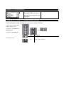
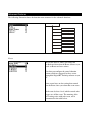
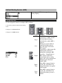
1
Link to Download Desktop Software:
HTTP://SUPPORT.NOMADIO.NET/REACT
User’s Guide
Link to Download Desktop Software:
SUPPORT.NOMADIO.NET/REACT
Copyright 2006 Nomadio
Published November, 2006
Table of Contents
Getting to Know Your React .................................................................................................................8
Power Switch...............................................................................................................................8
Display Screen .............................................................................................................................8
Navigation Buttons ......................................................................................................................8
Selection Buttons .........................................................................................................................9
Trim Buttons................................................................................................................................9
Grip Buttons ................................................................................................................................9
Charging and Installing Batteries ....................................................................................................10
Installing the Batteries ....................................................................................................................10
Charging the Batteries ....................................................................................................................11
Installing the Transceiver................................................................................................................12
Mounting the Transceiver ..........................................................................................................12
Connecting the Transceiver........................................................................................................12
Servo Connection..............................................................................................................13
FCC Compliance Reminder ..............................................................................................13
Installing the Optional Sensors............................................................................................................14
Receiver Battery Sensor .................................................................................................................14
Voltage Sensor ...............................................................................................................................14
Temperature Sensor........................................................................................................................15
Installation ......................................................................................................................................... 15
Connection .....................................................................................................................................15
Tachometer Sensor .........................................................................................................................16
Installation ..........................................................................................................................................16
Connection .....................................................................................................................................17
Connecting the Tach Sensor ................................................................................................................17
Binding the Transceiver..................................................................................................................18
How the Binding Process Works................................................................................................18
Binding your transceiver the first time.................................................................................................18
React Controls................................................................................................................................19
Top Menu Level ........................................................................................................................20
Steering Functions ..........................................................................................................................21
Steering Trim.............................................................................................................................21
Adjusting Steering Trim using the Function Menu .....................................................................22
Adjusting Steering Trim using the Steering Trim Buttons ..........................................................22
Steering Dual Rate .....................................................................................................................23
Adjusting Steering Dual Rate using the Function Menu .............................................................24
Adjusting Steering Dual Rate using the Trim Buttons ................................................................24
Dual Rate and End Point Adjustment .........................................................................................24
Steering Exponential ..................................................................................................................25
Adjusting Steering Exponential ......................................................................................................26
Steering Sub-Trim......................................................................................................................27
Adjusting Steering Sub-trim............................................................................................................... 27
Trim and EPA Interaction ..........................................................................................................27
Steering Left End Point ..............................................................................................................28
Use the navigation controls to adjust the left end point as follows: .............................................29
Trim and EPA Interaction ..........................................................................................................29
Steering Right End Point............................................................................................................30
Trim and EPA Interaction ..........................................................................................................31
Steering Servo Reverse ..............................................................................................................32
Changing the Steering Servo Reverse Setting.............................................................................32
Steering Servo Type...................................................................................................................32
Changing the Steering Servo Type .............................................................................................32
Steering Speed ...........................................................................................................................33
Changing the Steering Speed......................................................................................................33
Throttle Functions......................................................................................................................34
Throttle Trim .............................................................................................................................34
Adjusting Throttle Trim using the Function Menu......................................................................35
Adjusting Throttle Trim using the Trim Button ..........................................................................35
Trim and EPA Interaction ..........................................................................................................35
Throttle Dual Rate .....................................................................................................................36
Adjusting Throttle Dual Rate using the Function Menu..............................................................37
Adjusting Throttle Dual Rate using the Trim Button ..................................................................37
Dual Rate and End Point Adjustment .........................................................................................37
Adjusting Throttle Dual Rate Increment ............................................................................................. 37
Throttle Exponential ..................................................................................................................38
Adjusting Throttle Exponential ..................................................................................................38
Brake Exponential......................................................................................................................39
Adjusting Brake Exponential .....................................................................................................39
Throttle Sub-Trim ......................................................................................................................40
Adjusting Throttle Sub-trim .......................................................................................................40
Trim and EPA Interaction .................................................................................................40
Brake End Point .........................................................................................................................41
Adjusting the Brake End Point ...................................................................................................42
Trim and EPA Interaction ..........................................................................................................42
Throttle End Point......................................................................................................................43
Adjusting the Throttle End Point ................................................................................................44
Trim and EPA Interaction ..........................................................................................................44
Throttle Dual Rate Mode............................................................................................................45
Changing the Throttle Dual Rate Mode......................................................................................45
Throttle Servo Reverse...............................................................................................................46
Changing the Throttle Servo Reverse Setting .............................................................................46
Throttle Servo Type ...................................................................................................................47
Changing the Throttle Servo Type..............................................................................................47
Throttle Speed............................................................................................................................48
Changing the Throttle Speed ......................................................................................................49
Interaction with other Settings....................................................................................................49
Channel 3 and Channel 4 Servo Functions .................................................................................50
Channels 3 / 4 Servo Trim..........................................................................................................50
Adjusting Channel 3 / 4 Servo Trims .........................................................................................51
Trim and EPA Interaction .................................................................................................................. 51
Channel 3 / 4 Servo Dual Rate ..................................................................................................52
Adjusting Channel 3 /4 Servo Dual Rate ....................................................................................52
Dual Rate and End Point Adjustment..............................................................................................53
Low End Point ................................................................................................................................... 53
Adjusting the Low End Point .....................................................................................................54
High End Point ..........................................................................................................................55
Adjusting the High End Point .........................................................................................................56
Channel 3 / 4 Dual Rate Mode ...................................................................................................57
Changing the Channel 3 / 4 Dual Rate Mode..............................................................................57
Channel 3 /4 Servo Reverse .......................................................................................................58
Changing the Channel 3 / 4 Servo Reverse Setting .....................................................................58
Channel 3 / 4 Servo Type ...........................................................................................................59
Changing the Channel 3 / 4 Servo Type .....................................................................................59
Channel 3 / 4 Servo Mode ..............................................................................................................60
Changing the Channel 3 / 4 Servo Mode.........................................................................................60
Channel 3 / 4 Servo Speed .........................................................................................................61
Changing the Channel 3 / 4 Servo Speed...................................................................................62
Interaction with other Settings............................................................................................................ 62
Advanced Features.....................................................................................................................63
Event Summary ..............................................................................................................................64
Event ................................................................................................................................64
Idle Up............................................................................................................................................... 65
Configuring Idle Up ...................................................................................................................65
AutoStart........................................................................................................................................66
Configuring AutoStart................................................................................................................66
Antilock Braking System (ABS).....................................................................................................67
Configuring ABS .......................................................................................................................67
Failsafes .........................................................................................................................................68
Setting Failsafe Modes ...................................................................................................................68
Setting Failsafe Positions................................................................................................................69
Calculation method ............................................................................................................................ 70
Measurement method........................................................................................................71
Tach (RPM)....................................................................................................................................72
Tank Mode......................................................................................................................................... 73
Activating / Deactivating Tank Mode.........................................................................................73
Using The Timer Function .........................................................................................................73
Model Management ...................................................................................................................74
Active Model..................................................................................................................................74
Selecting the Active Model.............................................................................................................74
New Model.....................................................................................................................................75
Creating a New Model....................................................................................................................75
Delete Model..................................................................................................................................76
Deleting a Model .......................................................................................................................76
Copy Model ...............................................................................................................................77
Copying a Model .......................................................................................................................77
Rebinding .......................................................................................................................................78
Rebinding to a Model .....................................................................................................................78
Controller Setup.........................................................................................................................79
Vibrator .....................................................................................................................................79
Contrast ............................................................................................................................................. 79
Adjusting the Display Contrast Level.........................................................................................79
Units ..........................................................................................................................................80
Selecting Unit System................................................................................................................80
Calibrate ............................................................................................................................................ 81
Recalibrating the React ..............................................................................................................81
About.........................................................................................................................................82
Viewing the React About Screen................................................................................................82
React Digital RC Desktop ...................................................................................................................83
Minimum System Requirements.....................................................................................................83
Installing the RC Desktop...............................................................................................................84
Connecting the React to your Computer .........................................................................................87
2. Plug the smaller end of the included USB cable into the cable with the matching USB connector
inside the React’s battery compartment. ............................................................................................. 87
Using the React Digital RC Desktop...............................................................................................88
Registration ....................................................................................................................................89
Registering a Second Computer......................................................................................................90
Receiving Settings From the React .................................................................................................91
Editing Settings..........................................................................................................................91
Using Softkeys....................................................................................................................................92
Saving Settings...............................................................................................................................93
Sending Settings to the React .....................................................................................................93
Installing React Firmware ..........................................................................................................93
Specifications.............................................................................................................................94
React Controller .............................................................................................................................94
Transceiver ................................................................................................................................94
Support ......................................................................................................................................95
Statement of Compliance ....................................................................................................................97
FCC Compliance Statement............................................................................................................97
RF Exposure Statement ..................................................................................................................97
Modular Approval Statement..........................................................................................................98
Racing Association Approvals........................................................................................................98
Nomadio 1 Year Limited Warranty .....................................................................................................99
Warranty Coverage ....................................................................................................................99
Exclusions and Limitations ........................................................................................................99
Consumer Protection Laws ......................................................................................................101
Obtaining Warranty Service .....................................................................................................101
Getting to Know Your React
Power Switch
This switch turns the React on and off. It is
recessed to prevent accidental switching during
travel or use.
Display Screen
Driving Screen
This is the screen you’ll be seeing 95%
of the time while using the React. It
displays radio and battery status,
telemetry data that you select and your
servo information.
Menu Screen
This screen is the gateway to the
React’s menu system, which is
described in detail later. You can
always go back to the driving screen by
just pressing the menu key.
Navigation Buttons
Button
In the drive screen
In the function menu
Moves to next higher menu item
Moves to next lower menu item
Displays previous reading
Displays next reading
Decreases selected value
•
•
•
•
Increases selected value
Goes to next submenu
Goes to selected submenu
Saves the change to the selected
setting
Selection Buttons
Button
In the function menu
Sets the currently edited value to its maximum
value
Sets the currently edited value to its minimum
value
Cancels any changes made and resets value to
where it was before editing started
Resets the value to its factory default
Trim Buttons
T2
T1
Button
T3
In the drive screen
T1
Adjusts the steering trim
T2
Adjusts the steering dual rate setting
T3
Adjusts the throttle dual rate setting
T4
Adjusts the throttle trim
T4
Grip Buttons
Performs shifting action on channel 3
Charging and Installing Batteries
The React is powered by a 4 cell battery pack(included).
Also inside the battery compartment is the 4 wire Receiver Programming Cable. This cable can be
plugged into the receiver’s TACH pins in order to upgrade the software on the receiver. The RC
Desktop will instruct you when a software upgrade is available.
Installing the Batteries
1. Plug the battery connector into the receptacle in the battery compartment. Refer to
photo for battery installation.
Warning!!!! Plugging the battery in backwards will damage the React!!!!!!!!
2. Place the battery holder in the battery compartment. Make sure the wires do not
pinch.
3. Slide the battery compartment cover into place.
Charging the Batteries
Make sure the Nomadio React battery pack is properly installed and the React is switched
off. Batteries other than the Nomadio React battery pack cannot be charged by the
React, and attempting to do so will void the warranty. Batteries other than the Nomadio
React battery pack must be removed prior to connecting over USB for any reason, even
when just using RC Desktop.
Connect the USB cables and insert the USB cable into a PC or powered USB hub.
The React will sense a low battery, and will begin charging automatically. To manually
begin charging a battery, hit the “+” key.
The LCD status will display “Charging”, and the timer at the bottom of the screen will
begin. Charging a fully depleted battery should take between 4 and 6 hours.
When the React senses that a battery is fully charged, the LCD status will display “Charge
Done” and will stop charging.
It is safe to manually stop the charging process, by hitting the “-“ key.
If charging fails for any reason, the LCD status will display “Charge Fault”. If this occurs,
verify that:
You are using the Nomadio React battery pack.
The battery pack is properly installed.
The USB cables are connected properly.
Installing the Transceiver
Mounting the Transceiver
•
Install the transceiver so it is protected from vibration or shock.
•
Use double-sided tape or Velcro® to mount the transceiver.
•
Position the transceiver where it will not contact other solid components.
Mount the transceiver away from moving parts, sharp corners, and possible contaminants (fuel,
dirt, etc.).
•
•
When possible, waterproof and protect the transceiver by wrapping it in foam rubber and
placing it in a rubber balloon or plastic bag. If you accidentally get moisture or fuel inside the
transceiver, intermittent or erratic operation may result.
•
Position the transceiver so the sensors can be easily connected to it.
Antenna
•
The thinner portion at the end of the antenna wire must be outside the vehicle body
•
DO NOT CUT the antenna wire
Connecting the Transceiver
Servo Input Plugs
The transceiver is designed to use Futaba J-style input plugs
with wiring order as shown in the diagram.
Servo lead wires MUST be in this order. If the servo wires
are in a different order, you must re-order the wires in the
input plug. Check with your servo manufacturer about the
color and order of the servo lead wiring.
When you insert the servo input plug into the transceiver,
note that the input plug may have an alignment tab. Orient
the alignment tab properly before inserting the input plug.
To remove in input plug from the transceiver, pull the input
plug rather than the servo wires.
Servo Connection
Connect the servos to the appropriate positions in the transceiver:
Connect…
…into transceiver receptacle
Receiver battery / Channel 4 servo
“Power”
Steering servo
“Steering”
Throttle servo or ESC
“Throttle”
Shifting servo
“Shft/CH3”
FCC Compliance Reminder
If you install the React transceiver inside of a vehicle, and you are not the final end user, FCC
regulations require you to make the React Transceiver’s FCC ID easily visible to the end user. See the
FCC Compliance section for more information:
Installing the Optional Sensors
Your React radio system has several optional sensors that you can install in your vehicle and connect to
the transceiver. When properly installed and connected, these sensors will send information back to the
React so that you can monitor the readings while you drive.
Receiver Battery Sensor
The transceiver monitors the receiver battery voltage from the POWER receptacle. There is no
installation necessary for this sensor.
Voltage Sensor
The voltage sensor is used to monitor the voltage of a separate battery pack (for example, an electric
car’s main battery pack). In a Nitro car, this sensor is not needed.
Connecting the Voltage Sensor
1. Connect the RED wire of the voltage sensor to the positive
terminal and the BLACK wire of the voltage sense to the negative
terminal of the battery pack you want to monitor.
2. Carefully route, protect, and secure the sensor wires.
3. Plug the voltage sensor into the BATT receptacle. If your voltage
sensor only has two wires, connect the RED wire to the center pin
and the black wire to either outside pin.
Temperature Sensor
The temperature sensor is used to monitor the temperature of a vehicle
component such as a main battery pack, electric motor, or nitro engine.
Installation
The green circuit board of the sensor is the active measuring element. Install the sensor so that this
board is pressed against the item whose temperature you wish to measure.
The sensor has been designed to be thin enough to fit between the fins on a heat sink. The mounting
wires are strong enough to be used to hold the sensor in place by wrapping them around a cylinder head
or ESC heat sink. Alternately, a high-temperature epoxy may be used to secure the sensor.
When installing on a nitro motor, place the sensor as low as possible on the head, opposite the exhaust
port. The sensor may also be installed on an electric motor, battery pack, or ESC heat sink.
Connection
After you install the temperature sensor in the vehicle, plug it into the “Sensor 1” or “Sensor 2”
receptacle.
The four-pin connector on the sensor cable has only three wires populated. The unpopulated pin
should be the one furthest from the connector key in the receiver plastic.
The React transceiver will automatically detect which sensors are installed.
Tachometer Sensor
The tachometer (“tach”) sensor is used to monitor the rotation speed of a vehicle component such as a
drive shaft and this speed is converted into vehicle speed.
You will need to measure the distance your model rolls in order to provide the React with enough
information to give you an accurate speed. We recommend that you get a tape measure and measure
several rotations of the wheel to reduce the measurement error.
Installation
1. Choose the mounting location
In the drive train, after any clutch or transmission. We recommend that you do not try to mount the
magnets on your motor for magnetic reasons (electric motors) and balance reasons (nitro motors).
Smaller diameter mounting points are better.
The tach sensor must be able to be mounted within 1-2mm of the magnet surface, so you’ll need a solid
mounting point that can position the sensor in the right place.
The completed installation should be rigid enough that proximity is maintained without the magnets
impacting the sensor.
2. Install the magnets
Stick two magnets together, mark the exposed faces, then separate them.
Install the magnets with the marked sides out, exactly 180º apart to preserve rotational balance.
IMPORTANT: For correct operation, the sensor must see alternating north and south magnetic poles.
Ideally, countersink the magnets into the surface.
3. Install the tach sensor
The sensor side of the tach circuit board must be mounted closest to magnets. The sensor is on the
opposite side from the large chip that protrudes from the shrink tubing. The graphic above shows where
the sensor is so you can mount it correctly.
When moving, the magnets should pass directly over the center of the sensor.
We have used a variety of methods of mounting tach sensors, depending on the car and the chosen
location. Some ideas include cable ties, epoxy/hot glue, wire, making a wooden housing that holds the
sensor in a specific place, etc. The only “wrong” way to mount it is if the magnets hit the sensor or are
too far away, or if the sensor moves while the car is running.
Connection
Connect
optional Tach
sensor here.
Connecting the Tach Sensor
After you install the tach sensor in the vehicle, plug it into the “DIGITAL” receptacle.
Plug connector into transceiver – tachometer connector pin 1 (designated with a red wire and an arrow
on the connector body housing) corresponds with the keyed end of transceiver digital port connector
(labelled “digital”). The transceiver will automatically detect which sensors are installed.
Test your sensor’s installation. Power on React and transceiver and bind them
Verify communication between tachometer and transceiver by selecting RPM reading from drive
screen
Correct mechanical installation can be verified by noting RPM value changes on your controller screen
while you spin the wheels of your model.
If you don’t see changing RPM values, the magnets or sensor are out of position, or the sensor could be
plugged into the wrong sensor port on your transceiver. If your magnets are hitting the sensor or a part
of your car when the wheels are turning, you must re-mount them so they do not hit anything.
Binding the Transceiver
The binding process “locks” the React and a transceiver together so that they listen only to each other.
Since the React has forty model memories, it is possible that your React will be used to communicate
with as many as forty transceivers. You must therefore perform the binding process once for each
transceiver that will communicate with your React.
Note that the React cannot communicate with all of the transceivers at the same time, but rather the
React will communicate only with the transceiver associated with the React’s currently active model.
For more information, see “Managing Models” later in this instruction manual.
How the Binding Process Works
The binding process is set in motion by depressing the “bind” button on the transceiver when the React
is in “bind mode.” This clears the React ID saved on the transceiver, and allows it to connect to a
React.
When in “bind mode” the React will listen for messages from interested transceivers. When a message
is received the transceiver VIN (the number under the barcode on the FCC label) is displayed, and you
are given the option of connecting to that transceiver or looking for another.
Now, every time you turn on the React and set it to the appropriate model ID (see “Managing Models”
later in this manual), the React sends messages to the appropriate VIN. When you turn on the vehicle’s
transceiver, the transceiver looks for messages from the bound React only.
Binding your transceiver the first time
1. Install a transceiver into your vehicle. (For this example, install a transceiver into your electric
touring car, which will be known to the React as “Model 1.”)
2. In the React’s “Manage Models” function menu, go to “Active Model” and select the appropriate
model ID for the vehicle you are going to bind to. (For this example, select “Model 1.”)
3. After putting your model on a stand to prevent runaways, power up the vehicle and transceiver.
4. In the React’s “Manage Models” function menu, select “Rebind.”
5. Depress and hold the transceiver’s “bind” button until the onboard LED illuminates (you can use an
extended paperclip, ball point pen, small screwdriver, etc).
6: Confirm binding on your React by pressing the “OK” button as the transceiver VIN number is
displayed.
The binding process is now complete.
React Controls
The functions of the React are controlled through the function menu and/or trim controls.
To perform this action...
Press......
Toggles between the driving screen and the
function menu or returns to the previous level
from a sub-menu
Menu: Go to the selected sub-menu
Menu: Move to the next higher menu item.
Menu: Move to the next lower menu item.
Menu: Go to the selected sub-menu.
Drive: Display next statistic.
Menu: Decrease the selected value setting.
Drive: Display previous statistic.
Menu: Set currently edited value to maximum.
Menu: Set currently edited value to minimum.
Menu: Cancel changes made to the current
parameter.
Menu: Reset currently edited value to factory
default.
Top Menu Level
The following illustration shows the function menu structure for the top-level menu. All main submenus may be accessed from the top menu level. Channels 3 & 4 have identical setups, and are
documented together.
Manage Models
Active Model
New Model
Delete Model
Copy Model
Rebind
Steering Functions
Steering Trim
Steering trim adjusts the center
point of the steering servo by
adjusting the center point within
the steering servo’s total travel
range. Unlike steering sub-trim,
the steering left and right end
points are unaffected by steering
trim; by moving the center point
of the steering servo using trim,
the center position moves closer
to one end point or the other.
Steering trim should be used
only after you have initially
adjusted steering sub-trim.
Steering Trim
Steering (Ch1)
Throttle (Ch2)
Shift (Ch3)
Ch4
On the driving screen, steering
trim is represented by the
position of the pointer on the
upper bar.
As you change the steering trim, it is shown graphically on the driving screen trim indicator bars:
Steering trim is centered in range (value = 0)
Steering trim is offset to the RIGHT (+ve value
Steering trim is offset to the LEFT (-ve value)
If you find that you have to use a large amount of steering trim to get the vehicle to drive straight, you
should consider resetting the steering trim to 0 and re-adjusting the servo horn on the servo output
shaft.
Adjusting Steering Trim using the Function Menu
Use the navigation controls to adjust steering trim as follows:
1. Access the top function menu from
the driving screen.
2. Navigate to the Steering (Ch1) menu.
or
then
3. Navigate to Trim.
or
Value
0
4. Change the value.
or
-ve value
(-100 -1)
+ve value
(1 100)
Description
Steering trim is centered within the servo
range.
Steering trim is to the LEFT.
Steering trim is to the RIGHT.
Adjusting Steering Trim using the Steering Trim Buttons
Push the trim button forward to advance the trim, backward to reduce it.
A trim (or sub-trim) setting of 100 is equivalent to an End point setting of 50.
Steering Dual Rate
Steering dual rate adjusts the
range of servo movement when
the steering wheel is fully turned
in either the left or right
direction. This is used to increase
or decrease the steering
sensitivity across the entire servo
range. The steering dual rate
value is applied to both left and
right sides, and is expressed as a
percentage of servo range
(configured by end point
adjustments).
Dual Rate Range
Steering (Ch1)
Throttle (Ch2)
Shift (Ch3)
Ch4
On the driving screen, steering dual rate range is
represented by the solid length of the upper bar.
The total length of the bar (solid and dotted)
represents the servo range. The length of the solid
bar represents the range set by the dual rate value.
As you change the dual rate setting it is shown graphically on the driving screen trim indicator bars:
Full servo range is used.
Lower dual rate value reduces servo range.
Adjusting Steering Dual Rate using the Function Menu
Use the navigation controls to adjust steering dual rate as follows:
1. Access the top function menu from
the driving screen.
2. Navigate to the Steering (Ch1)
menu.
or
: then
3. Navigate to Dual Rate.
or
Value
0
4. Change the value.
or
1-99
100
Description
Steering servo range is set to minimum.
Steering servo range is set to a percentage of full
range.
For example, value “50” gives 50% of full servo
range.
Steering servo range is set to full (100%)
Adjusting Steering Dual Rate using the Trim Buttons
You can also use the T2 trim button to adjust the steering dual rate.
Dual Rate and End Point Adjustment
Full servo range is determined by the left and right end point adjustments. The dual rate value
determines the relative servo range between the left and right end points. The servo will never move
beyond the set end point adjustments, no matter what dual rate setting is applied.
Steering Exponential
Steering exponential adjusts how quickly or
slowly the steering servo responds with respect to
the amount that the steering wheel is turned. This
affects the sensitivity of the steering servo near its
neutral position (center).
Adjusting the steering exponential value affects
both left and right steering response at the same
rate.
Servo travel
RIGHT
-ve exponential
(milder response)
0% (linear)
Steering wheel
turned full LEFT
Neutral
-1 ~ -100%
(mild)
A negative (-ve) exponential value gives a milder
steering response near the steering neutral point,
making it LESS responsive to small steering
inputs, without affecting total travel like Dual
Rate would.
Steering w heel
tur ned full RIGHT
Servo travel
LEFT
Servo travel
RIGHT
1~100%
(quick)
+ve exponential
(quicker response)
0% ( linear)
Steering wheel
turned full LEFT
Neutral
Servo travel
LEFT
A positive (+ve) exponential value gives a quicker
steering response near the steering neutral point,
making it MORE responsive to small steering
inputs, without affecting total travel like Dual
Rate would.
Steering wheel
tur ned full RIGHT
Adjusting Steering Exponential
Use the navigation controls to adjust steering exponential as follows:
1. Access the top function menu from the
driving screen.
2. Navigate to the Steering (Ch1) menu.
or
then
3. Navigate to Expo.
or
Value
0
4. Change the value.
or
Description
Neutral steering response (linear).
-ve value
(-1 to -100)
Milder steering response near center.
+ve value
(1 to 100)
Quicker steering response near center.
Steering Sub-Trim
Steering sub-trim adjusts the
center point of the steering servo.
This differs from steering trim in
that steering sub-trim adjusts the
servo’s entire travel range; by
moving the center point of the
servo, the left and right end
points (left, right) stay the same
relative “distance” from the
servo center.
Steering sub-trim should be initially adjusted after you have assembled your vehicle’s steering system;
after you begin driving the vehicle, use steering trim to make fine adjustments to center the steering
within the total steering range. If you find that you have to use a large amount of steering sub-trim to
get the vehicle to drive straight, you should consider resetting the steering sub-trim to 0 and readjusting the servo horn on the servo output shaft.
Adjusting Steering Sub-trim
Use the navigation controls to adjust steering sub-trim as follows:
1. Access the top function menu from
the driving screen.
2. Navigate to the Steering (Ch1) menu.
or
then
3. Navigate to Sub Trim.
or
Value
0
4. Change the value.
or
-ve value
(-100 -1)
+ve value
(1 100)
Description
Steering sub-trim is centered within the servo
range.
Steering sub-trim is to the LEFT.
Steering sub-trim is to the RIGHT.
Trim and EPA Interaction
A trim (or sub-trim) setting of 100 is equivalent to an End point setting of 50.
Steering Left End Point
The steering left end point value
adjusts how far the steering
servo turns to the LEFT with
respect to its full range of motion
to the left. End point adjustment
should be adjusted prior to other
steering settings, as the left end
point value affects other steering
settings.
The left end point is set independently of the right end point (which adjusts how far the steering servo
turns to the RIGHT). The left end point setting should be used to do the following:
Limit steering throw to reduce mechanical binding or servo strain that may occur on full servo throw to
the left. For example, if the servo is trying to turn the steering system to the left farther than it is
mechanically able.
Adjust steering throw to change steering characteristics when turning to the left.
For example, if the current amount of steering throw to the left causes oversteer or understeer when
turning to the left.
Left End Point
Steering (Ch1)
Throttle (Ch2)
Shift (Ch3)
Ch4
On the driving screen, the left end point is
represented by the length of the bar to the left of
the pointer on the upper bar.
The greater the left length of the bar, the greater
the left end point value.
The position of the pointer on the bar is affected
by the end point settings (left and right) and trim
settings.
Changing the left end point value has the following visual effect on the driving screen bars.
Left end point value is approximately the same as
the right end point value.
Increased left end point value (more servo travel
to the left is possible).
Decreased left end point value (less servo travel to
the left is possible).
The position of the pointer on the bar is affected by the steering end point settings (left and right) and
trim setting; increasing the left end point value may visually appear to have the same effect as
decreasing the right end point value.
An end point setting of 100 (the default) is typical for most servos, and should always be used for
ESCs. Larger setting values will overdrive most servos.
Use the navigation controls to adjust the left end point as follows:
1. Access the top function menu from the
driving screen.
2. Navigate to the Steering (Ch1) menu.
or
then
3. Navigate to Left End Point.
or
Value
0
4. Change the value.
or
1-200
200
Description
Minimum left end point; allows NO turning motion
to the left.
Left end point value is set to a percentage of full
left-turning range.
Maximum left end point (will overdrive most
servos)
Trim and EPA Interaction
A trim (or sub-trim) setting of 100 is equivalent to an End point setting of 50.
Steering Right End Point
The steering right end point
value adjusts how far the
steering servo turns to the
RIGHT with respect to its full
range of motion to the right. End
point adjustment should be
adjusted prior to other steering
settings, as the right end point
value affects other steering
settings.
The right end point is set independently of the left end point (which adjusts how far the steering servo
turns to the LEFT). The right end point setting should be used to do the following:
Limit steering throw to reduce mechanical binding or servo strain that may occur on full servo throw to
the right. For example, if the servo is trying to turn the steering system to the right farther than it is
mechanically able.
Adjust steering throw to change steering characteristics when turning to the right.
For example, if your car is oversteering when turning to the right, then reduce the Right End Point
value to reduce the range of the steering servo on the right.
Right End Point
Steering (Ch1)
Throttle (Ch2)
Shift (Ch3)
Ch4
On the driving screen, the right end point is
represented by the length of the bar to the right of
the pointer on the upper bar.
The greater the right length of the bar, the greater
the right end point value.
The position of the pointer on the bar is affected
by the end point values (left and right) and trim
setting.
Changing the right end point value has the following visual effect on the driving screen bars.
Right end point value is approximately the same
as the left end point value.
Increased right end point value (more servo travel
to right is possible).
Decreased right end point value (less servo travel
to right is possible).
The position of the pointer on the bar is affected by the steering end point values (left and right) and
trim setting; increasing the right end point value may visually appear to have the same effect as
decreasing the left end point value.
An end point setting of 100 (the default) is typical for most servos, and should always be used for
ESCs. Larger setting values will overdrive most servos
Use the navigation controls to adjust the right end point as follows:
1. Access the top function menu from the
driving screen.
2. Navigate to the Steering (Ch1) menu.
or
then
3. Navigate to Right End Point.
or
Value
0
4. Change the value.
or
1-200
200
Description
Minimum right end point; allows NO turning motion
to the right.
Right end point setting is set to a percentage of full
right-turning range.
Maximum right end point (will overdrive most servos)
Trim and EPA Interaction
A trim (or sub-trim) setting of 100 is equivalent to an End point setting of 50
Steering Servo Reverse
Steering Servo Reverse
reverses the direction the
servo moves upon
receiving an input from
the steering wheel.
Changing the Steering Servo Reverse Setting
Use the navigation controls to change the steering servo reverse setting as follows:
1. Access the top function menu from the
driving screen.
2. Navigate to the Steering (Ch1) menu.
or
then
3. Navigate to Servo Reverse.
or
Value
4. Change the value.
Description
Off
Standard servo direction.
On
Reversed servo direction.
or
Steering Servo Type
Steering servo type lets you select the type of
steering servo (analog or digital) in the vehicle.
Analog servos are sent signals at 50 frames/sec,
while Digital servos are sent signals at 100
frames/sec. If you have high-end analog servos,
they may operate better with the digital setting, try
both settings and choose the best performance.
Changing the Steering Servo Type
Use the navigation controls to change the steering servo type as follows:
1. Access the top function menu from
the driving screen.
2. Navigate to the Steering (Ch1) menu.
or
then
3. Navigate to Servo Type.
or
4. Change the value.
Value
Description
Analog
Steering servo is analog.
Digital
Steering servo is digital.
or
Steering Speed
Steering speed allows you to limit the maximum
speed that the steering servo will be driven to
match your movements on the wheel. There are
three parameters that can be adjusted to precisely
set up your limiting.
Trigger sets the minimum amount of control input
before the speed limiter becomes active. At 0%,
limiting is always active (input is always >= 0%).
At 50%, limiting is only active if the wheel is
turned half way or more.
Input speed determines the limited speed that is
applied to motions away from center that are
above the trigger setting. 100 is the maximum
servo movement rate. 1 is the minimum rate.
Default is 100 (full speed)
Return speed determines the limited speed that is
applied to motions back toward center that are
above the trigger setting. 100 is the maximum
servo movement rate. 1 is the minimum rate.
Default is 100 (full speed)
Changing the Steering Speed
Interaction with other parameters
Servo Speed is applied after Expo. The trigger level for Servo Speed refers to the curved input value.
Use the navigation controls to change the steering servo type as follows:
1. Access the top function menu from
the driving screen.
2. Navigate to the Steering (Ch1) menu.
or
then
3. Navigate to Steering Speed.
or
Value
Input
Speed
4. Change the values.
or
Return
Speed
Trigger
Description
The percentage of full speed applied to servo
motion away from center once the trigger amount
has been exceeded.
The percentage of full speed applied to servo
motion toward center once the trigger amount has
been exceeded.
The threshold above which speed limiting will be
applied.
Throttle Functions
The following illustration shows the function menu structure for the throttle functions:
Throttle Trim
Throttle trim adjusts the resting
(centered) position of the throttle
servo horn (electric or nitro vehicle)
or the neutral point of an ESC
(electric vehicle).
When initially setting up the vehicle,
the throttle trim setting should be set
to 0. On a throttle servo, the servo
horn should be positioned as
appropriate on the servo.
Throttle Trim
On the driving screen, throttle
trim is represented by the
position of the pointer on the
middle bar.
Changing the throttle trim has the following visual effect on the driving screen bars:
Throttle trim is centered in range (value = 0)
Throttle trim is offset to throttle end (+ve value)
Throttle trim is offset to brake end (-ve value)
Adjusting Throttle Trim using the Function Menu
Use the navigation controls to adjust throttle trim as follows:
1. Access the top function menu from the
driving screen.
2. Navigate to the Throttle (Ch2) menu.
or
then
3. Navigate to Trim.
or
Value
0
4. Change the value.
or
-ve value
(-100 -1)
+ve value
(1 100)
Description
Throttle trim is centered within servo range.
Throttle trim is to the BRAKE end.
Throttle trim is to the THROTTLE end.
Adjusting Throttle Trim using the Trim Button
You can also use the T3 trim button to adjust throttle trim.
Trim and EPA Interaction
A trim (or sub-trim) setting of 100 is equivalent to an End point setting of 50.
Throttle Dual Rate
Throttle dual rate adjusts the
range of servo movement when
the throttle trigger is moved from
full brake to full throttle position.
This is used to increase or
decrease the throttle sensitivity
across the entire servo range.
The throttle dual rate value is
applied to both throttle and brake
end, and is expressed as a
percentage of servo range
(configured by end point
adjustments).
Throttle Dual Rate Range
On the driving screen, throttle
dual rate range is represented by
the solid length of the middle
bar.
The total length of the bar (solid
and dotted) represents the servo
range. The length of the solid bar
represents the servo range set by
the dual rate value.
Changing the dual rate setting has the following visual effect on the driving screen bars:
Full servo range is used.
Lower dual rate value reduces servo range.
Adjusting Throttle Dual Rate using the Function Menu
Use the navigation controls to adjust throttle dual rate as follows:
1. Access the top function menu from
the driving screen.
2. Navigate to the Throttle (Ch2)
menu.
or
then
3. Navigate to Dual Rate.
or
Value
1
4. Change the value.
or
Description
Throttle/brake range is set to minimum.
1-99
Throttle/brake range is set to a percentage of full range.
For example, value “50” gives 50% of full servo range.
100
Throttle/brake range is set to full (100%)
Adjusting Throttle Dual Rate using the Trim Button
You can also use the T1 trim button to adjust throttle dual rate.
Dual Rate and End Point Adjustment
Full servo range is determined by the throttle and brake end point adjustments. The dual rate value
determines the relative servo range between the throttle and brake end points. The servo will never
move beyond the set end point adjustments, no matter what dual rate setting is applied.
Adjusting Throttle Dual Rate Increment
Use the navigation controls to adjust throttle dual rate increment as follows:
1. Access the top function menu from
the driving screen.
2. Navigate to the Throttle (Ch2) menu
or
then
3. Navigate to DR Increment.
or
Value
4. Change the value.
or
1-20
Description
Throttle dual rate value changes by set
increment.
Use smaller values for finer dual rate control.
Use larger values for coarser dual rate
control.
Throttle Exponential
Throttle exponential adjusts how quickly or
slowly the throttle servo responds with respect to
the amount that the throttle trigger is moved to the
THROTTLE end. This affects the sensitivity of
the throttle servo near its neutral position.
Adjusting the throttle exponential does not affect
the brake exponential; these settings are set
individually.
Servo trave l
THROTTLE
A negative (-ve) exponential value gives a milder
throttle response near the throttle neutral point,
making it LESS responsive to small throttle
inputs, without changing overall throttle travel
like Dual Rate would.
0% (linear)
-1 ~ -100%
(mild)
Neutral
F ull throt tle
-ve exponential
(milder response)
Servo trave l
THROTTLE
A positive (+ve) exponential value gives a quicker
throttle response near the throttle neutral point,
making it MORE responsive to small throttle
inputs, without changing overall throttle travel
like Dual Rate would.
1~100%
( quick)
0% (linear)
Neutral
F ull throt tle
+ve exponential
(quicker response)
Adjusting Throttle Exponential
Use the navigation controls to adjust throttle exponential as follows:
1. Access the top function menu from the
driving screen.
2. Navigate to the Throttle (Ch2) menu.
or
then
3. Navigate to Throttle Expo.
or
Value
4. Change the value.
or
0
-ve value
(-1 to -100)
+ve value
(1 to 100)
Description
Neutral throttle response (linear).
Milder throttle response near neutral.
Quicker throttle response near neutral.
Brake Exponential
Brake exponential adjusts how quickly or slowly
the throttle servo responds with respect to the
amount that the throttle trigger is moved to the
BRAKE end. This affects the sensitivity of the
throttle servo near its neutral position.
Adjusting the brake exponential does not affect
the throttle exponential; these settings are set
individually.
Ser vo travel
THROTTLE
A negative (-ve) exponential value gives a milder
braking response near the throttle neutral point,
making it LESS responsive to small braking
inputs, without changing overall throttle travel
like Dual Rate would.
0% (linear)
-1 ~ -100%
(mild)
Neutral
F ull throt tle
-ve exponential
(milder response)
Neutral
Full brake
A positive (+ve) exponential value gives a quicker
braking response near the throttle neutral point,
making it MORE responsive to small braking
inputs, without changing overall throttle travel
like Dual Rate would.
0% (linear)
1~100%
(quick)
Servo travel
BRAKE
+ve exponential
(quicker response)
Adjusting Brake Exponential
Use the navigation controls to adjust brake exponential as follows:
1. Access the top function menu from the
driving screen.
2. Navigate to the Throttle (Ch2) menu.
or
then
3. Navigate to Brake Expo.
or
Value
4. Change the value.
or
0
-ve value
(-1 to -100)
+ve value
(1 to 100)
Description
Neutral braking response (linear).
Milder braking response near neutral.
Quicker braking response near neutral.
Throttle Sub-Trim
Throttle sub-trim adjusts the
center point of the throttle servo.
This differs from throttle trim in
that throttle sub-trim adjusts the
servo’s entire travel range; by
moving the center point of the
servo, the throttle and brake end
points (throttle, brake) stay the
same relative “distance” from the
servo center.
Throttle sub-trim should be
initially adjusted before using
throttle trim, which is used to
make fine adjustments to center
the throttle within the total
steering range.
If you find that you have to use a large amount of throttle sub-trim to adjust the throttle position, you
should consider resetting the steering sub-trim to 0 and re-adjusting the servo horn on the servo output
shaft.
Adjusting Throttle Sub-trim
Use the navigation controls to adjust throttle sub-trim as follows:
1. Access the top function menu from
the driving screen.
2. Navigate to the Throttle (Ch2) menu.
or
then
3. Navigate to Sub Trim.
or
Value
0
4. Change the value.
or
-ve value
(-100 -1)
+ve value
(1 100)
Description
Throttle sub-trim is centered within the servo
range.
Throttle sub-trim is to the BRAKE end.
Throttle sub-trim is to the THROTTLE end.
Trim and EPA Interaction
A trim (or sub-trim) setting of 100 is equivalent to an End point setting of 50.
Brake End Point
The brake end point value
adjusts how far the throttle goes
to the BRAKE end with respect
to its full range of motion to the
brake end. End point adjustment
should be adjusted prior to other
throttle settings, as the brake end
point value affects other throttle
settings.
The brake end point is set
independently of the throttle end
point (which adjusts how far the
throttle moves to the
THROTTLE end).
The brake end point setting should be used to do the following:
Limit throttle throw to reduce mechanical binding or servo strain that may occur on full servo throw to
the brake end. For example, if the servo is trying to pull a mechanical brake linkage farther than it is
mechanically able.
Adjust braking range to reduce the full braking force of the vehicle.
On the driving screen, the brake
end point is represented by the
length of the bar to the left of the
pointer on the middle bar. The
greater the left length of the bar,
the greater the brake end point
value.
The position of the pointer on
the bar is affected by end point
settings (throttle and brake) and
trim setting.
Brake End Point
Changing the brake end point value has the following visual effect on the driving screen bars.
Brake end point value is approximately the same
as the throttle end point value.
Increased brake end point value (more servo travel
for BRAKING is possible).
Decreased brake end point value (less servo travel
for BRAKING is possible).
The position of the pointer on the bar is affected by end point settings (throttle and brake) and trim
setting; increasing the brake end point value may visually appear to have the same effect as decreasing
the throttle end point value.
An end point setting of 100 (the default) is typical for most servos, and should always be used for
ESCs. Larger setting values will overdrive most servos
Adjusting the Brake End Point
The brake end point value is a relative value, and is expressed as the percentage of full travel to the
BRAKE end. For example, setting the brake end point value to “100” allows the throttle to go to only
50% of full brake.
Use the navigation controls to adjust the brake end point as follows:
1. Access the top function menu from the
driving screen.
2. Navigate to the Throttle (Ch2) menu.
or
then
3. Navigate to Brake End Point.
or
Value
0
4. Change the value.
or
1-200
200
Description
Minimum brake end point; allows NO brake
travel.
Brake end point value is set to a percentage of full
braking travel.
Maximum brake end point (will overdrive most
servos)
Trim and EPA Interaction
A trim (or sub-trim) setting of 100 is equivalent to an End point setting of 50.
Throttle End Point
The throttle end point value
adjusts how far the throttle goes
to the THROTTLE end with
respect to its full range of motion
to the throttle end. End point
adjustment should be adjusted
prior to other throttle settings, as
the throttle end point value
affects other throttle settings.
The throttle end point is set
independently of the brake end
point (which adjusts how far the
throttle servo turns to the
BRAKE end).
The throttle end point setting should be used to do the following:
Limit throttle throw to reduce mechanical binding or servo strain that may occur on full servo throw to
the throttle end. For example, if the servo is trying to pull a mechanical throttle linkage farther than it is
mechanically able.
Adjust throttle range to reduce the top speed of the vehicle.
On the driving screen,
the throttle end point
is represented by the
length of the bar to
the right of the
pointer on the middle
bar. The greater the
right length of the
bar, the greater the
throttle end point
value.
The position of the
pointer on the bar is
affected by end point
values (throttle and
brake) and trim
setting.
Throttle End Point
Steering (Ch1)
Throttle (Ch2)
Shift (Ch3)
Throttle End Point
Ch4
Steering (Ch1)
Throttle (Ch2)
Shift (Ch3)
Ch4
Changing the throttle end point value has the following visual effect on the driving screen bars.
Throttle end point value is approximately the
same as the brake end point value.
Increased throttle end point value (more servo
travel for THROTTLE is possible).
Decreased throttle end point value (less servo
travel for THROTTLE is possible).
The position of the pointer on the bar is affected by end point values (throttle and brake) and trim
setting; increasing the throttle end point value may visually appear to have the same effect as
decreasing the brake end point value.
An end point setting of 100 (the default) is typical for most servos, and should always be used for
ESCs. Larger setting values will overdrive most servos
Adjusting the Throttle End Point
The throttle end point value is a relative value, and is expressed as the percentage of full travel to the
THROTTLE end.
Use the navigation controls to adjust the throttle end point as follows:
1. Access the top function menu from the
driving screen.
2. Navigate to the Throttle (Ch2) menu.
or
then
3. Navigate to Throttle End Point.
or
Value
0
4. Change the value.
or
1-199
200
Description
Minimum throttle end point; allows NO throttle.
Throttle end point value is set to a percentage of full
throttle travel.
Maximum throttle end point (will overdrive most
servos)
Trim and EPA Interaction
A trim (or sub-trim) setting of 100 is equivalent to an End point setting of 50.
Throttle Dual Rate Mode
Dual Rate Mode controls the behavior of the Dual
Rate setting for the throttle servo.
Changing the Throttle Dual Rate Mode
Use the navigation controls to change the dual rate mode as follows:
1. Access the top function menu
from the driving screen.
2. Navigate to the Throttle (Ch2)
menu.
or
then
3. Navigate to DR Mode.
or
Value
Description
Both
Dual rate affects travel in both direction
Throttle
4. Change the value.
or
Brake
Dual rate affects throttle travel only. Useful to limit
throttle inputs early in a run with an electric model.
Dual rate affects brake travel only. Useful to adjust
brakes on a nitro vehicle without affecting throttle travel.
Throttle Servo Reverse
Throttle servo reversing reverses
the direction the throttle servo
moves upon receiving an input
from the throttle trigger.
Changing the Throttle Servo Reverse Setting
Use the navigation controls to change the throttle servo reverse setting as follows:
1. Access the top function menu from the
driving screen.
2. Navigate to the Throttle (Ch2) menu.
or
then
3. Navigate to Servo Reverse.
or
Value
4. Change the value.
Description
Off
Standard servo direction.
On
Reversed servo direction.
or
Throttle Servo Type
Throttle servo type lets you select the type of
throttle servo (analog or digital) in the vehicle.
Analog servos are sent signals at 50 frames/sec,
while Digital servos are sent signals at 100
frames/sec.
If you are running an electric car with an ESC, it
may perform better with the digital setting. Some
ESCs may not operate at all with the higher frame
rate. Try both settings and choose the best
performance.
Changing the Throttle Servo Type
Use the navigation controls to change the throttle servo type as follows:
1. Access the top function menu from
the driving screen.
2. Navigate to the Throttle (Ch2) menu.
or
then
3. Navigate to Servo Type.
or
4. Change the value.
Value
Description
Analog
Throttle servo is analog.
Digital
Throttle servo is digital.
or
Throttle Speed
Throttle speed allows you to limit the maximum
speed that the throttle servo will be driven to
match your movements on the trigger. There are
four parameters that can be adjusted to precisely
set up your limiting.
Throttle Speed determines the percentage of full
speed that is applied to the throttle movements
that are above the throttle trigger setting. 100 is
maximum servo movement rate. 1 is minimum
rate. Default is 100 (full speed).
Brake Speed determines the percentage of full
speed that is applied to braking movements that
are above the trigger setting. 100 is maximum
servo movement rate. 1 is minimum rate. Default
is 100 (full speed).
Throttle Trigger sets the minimum amount of
control input before the speed limiter becomes
active. At 0%, limiting is always active (input is
always >= 0%). At 50%, limiting is only active if
the throttle is on half way or more.
Brake Trigger sets the minimum amount of
control input before the speed limiter becomes
active. At 0%, limiting is always active (input is
always >= 0%). At 50%, limiting is only active if
the brake is on half way or more.
Changing the Throttle Speed
Use the navigation controls to change the steering servo type as follows:
1. Access the top function menu from
the driving screen.
2. Navigate to the Steering (Ch1) menu.
or
then
3. Navigate to Throttle Speed.
or
Value
4. Change the values.
or
Throttle
Speed
Brake
Speed
Throttle
Trigger
Brake
Trigger
Description
The amount of limiting applied to servo throttle
motion once the trigger amount has been exceeded.
The amount of limiting applied to servo brake
motion once the trigger amount has been exceeded.
The percentage of full throttle range that will be
limited.
The percentage of full braking range that will be
limited.
Interaction with other Settings
Servo Speed is applied after Expo. The trigger levels refer to the curved input value.
ABS is applied after Brake Speed, so Brake Speed can limit how quickly the brake input moves to the
ABS Active region, but once there ABS pulses happen at full speed.
Servo Speed is applied after AutoStart, so if the AutoStart Level is set higher than the Throttle Speed
Trigger, the servo movement will be slowed.
Idle Up only takes effect when the trigger is centered. Throttle Speed can slow down the return to
center, and therefore slow down Idle Up activation. Once Idle Up is started, the servo will jump to the
set position.
Channel 3 and Channel 4 Servo Functions
Each of these servos can be used as a number of auxiliary functions such as shifting or acting as a
second braking or steering servo. The following illustration shows the function menu structure for
Channel 3 (Shift) and Channel 4 (Power):
Channels 3 / 4 Servo Trim
Channel 3 and Channel 4 servo
trim adjusts the resting
(centered) positions of the
servos.
When initially setting up the
vehicle, the shift servo trim
setting should be set to 0. On the
servo, the servo horn should be
positioned as appropriate on the
servo.
On the driving screen, Channel 3
and Channel 4 servo trims are
represented by the position of the
pointers on the bottom bars.
Ch3 and Ch4 Trims
Changing the servo trim has the following visual effect on the driving screen bars:
Servo trim is centered in range (value = 0)
Servo trim is offset to high end (+ve value)
Servo trim is offset to low end (-ve value)
Adjusting Channel 3 / 4 Servo Trims
Use the navigation controls to adjust shift servo trim as follows:
1. Access the top function menu
from the driving screen.
2. Navigate to the Channel 3 or
Channel 4 menu.
or
then
3. Navigate to Trim.
or
Value
0
4. Change the value.
or
-ve value
(-100 -1)
+ve value
(1 100)
Description
Shift servo trim is centered within the
servo range.
Shift servo trim is to the LOW end.
Shift servo trim is to the HIGH end.
Trim and EPA Interaction
A trim (or sub-trim) setting of 100 is equivalent to an End point setting of 50.
Channel 3 / 4 Servo Dual Rate
Channel 3 and Channel 4 servo
dual rates adjust the range of
servo movement when the grip
buttons are activated. The servo
dual rate value is applied to both
low and high ends, and is
expressed as a percentage of
servo range (configured by end
point adjustments).
On the driving screen, servo dual
rate range is represented by the
solid length of the bottom bar.
The total length of the bar (solid
and dotted) represents the servo
range. The length of the solid bar
represents the servo range as set
by the dual rate value.
Ch3 / Ch4 Dual Rate Ranges
Changing the dual rate setting has the following visual effect on the driving screen bars:
Full servo range is used.
Lower dual rate value reduces servo range.
Adjusting Channel 3 /4 Servo Dual Rate
Use the navigation controls to adjust servo dual rate as follows:
1. Access the top function menu
from the driving screen.
2. Navigate to the Channel 3 or
Channel 4 menu.
or
then
3. Navigate to Dual Rate.
or
Value
0
4. Change the value.
or
Description
Servo range is set to minimum (0%).
1-99
Servo range is set to a percentage of full range.
For example, value “50” gives 50% of full servo range.
100
Servo range is set to full (100%)
Dual Rate and End Point Adjustment
Full servo range is determined by the shift servo low and high end point adjustments. The dual rate
value determines the relative servo range between the low and high end points. The servo will never
move beyond the set end point adjustments, no matter what dual rate setting is applied.
Low End Point
The servo low end point value
adjusts the shift servo’s starting
position at reset. This is intended
to be low gear and goes with the
downshift sound event (reverse
the servo if this is not the case on
your model). The end point
adjustments should be adjusted
prior to other settings.
The low end point is set
independently of the high end
point (which adjusts how far the
servo moves to the HIGH end).
Ch3 / Ch4 Low End Points
On the driving screen, the low
end point is represented by the
length of the bar to the left of the
pointer on the lower bar. The
greater the left length of the bar,
the greater the low end point
value.
The position of the pointer on the
bar is affected by end point
settings (low and high) and trim
setting.
Low end point value is approximately the same as
the high end point value.
Increased low end point value (more servo travel
on LOW end is possible).
Decreased low end point value (less servo travel
on LOW end is possible).
The position of the pointer on the bar is affected by end point settings (low and high) and trim setting;
increasing the low end point value may visually appear to have the same effect as decreasing the high
end point value.
An end point setting of 100 (the default) is typical for most servos, and should always be used for
ESCs. Larger setting values will overdrive most servos
Adjusting the Low End Point
The low end point value is a relative value, and is expressed as the percentage of full travel to the LOW
end.
Use the navigation controls to adjust the low end point as follows:
1. Access the top function menu from
the driving screen.
2. Navigate to the Channel 3 or
Channel 4 menu.
or
then
3. Navigate to Low End Point.
or
Value
0
4. Change the value.
or
1-199
200
Description
Minimum low end point; allows NO travel to low end.
Low end point value is set to a percentage of travel
range to low end.
Maximum low end point (will overdrive most servos)
Trim and EPA Interaction
A trim (or sub-trim) setting of 100 is equivalent to an End point setting of 50.
High End Point
The shift servo high end
point value adjusts the
servo’s ending position
after shifting upwards.
This is intended to be
high gear and goes with
the upshift sound event
(reverse the servo if this
is not the case on your
model). The end point
adjustments should be
adjusted prior to other
settings.
The high end point is set
independently of the low
end point (which adjusts
how far the servo moves
to the LOW turns end).
On the driving screen,
the high end point is
represented by the
length of the bar to the
right of the pointer on
the upper bar. The
greater the right length
of the bar, the greater the
high end point value.
The position of the
pointer on the bar is
affected by end point
settings (low and high)
and trim setting.
Ch3 / Ch4 High End Points
Steering (Ch1)
Throttle (Ch2)
Shift (Ch3)
Ch4
Changing the high end point value has the following visual effect on the driving screen bars.
High end point value is approximately the same as
the low end point value.
Increased high end point value (more servo travel
on HIGH end is possible).
Decreased high end point value (less servo travel
on HIGH end is possible).
The position of the pointer on the bar is affected by end point settings (low and high) and trim setting;
increasing the high end point value may visually appear to have the same effect as decreasing the low
end point value.
An end point setting of 100 (the default) is typical for most servos, and should always be used for
ESCs. Larger setting values will overdrive most servos
Adjusting the High End Point
The high end point value is a relative value, and is expressed as the percentage of full travel to the
HIGH end.
Use the navigation controls to adjust the high end point as follows:
1. Access the top function menu from
the driving screen.
2. Navigate to the Channel 3 or
Channel 4 menu.
or
then
3. Navigate to High End Point.
or
Value
0
4. Change the value.
or
1-199
200
Description
Minimum high end point; allows NO travel to high end.
High end point value is set to a percentage of travel
range to high end.
Maximum high end point (will overdrive most servos)
Trim and EPA Interaction
A trim (or sub-trim) setting of 100 is equivalent to an End point setting of 50.
Channel 3 / 4 Dual Rate Mode
Dual Rate Mode controls the behavior of the Dual
Rate setting for the channel 3 and channel 4
servos.
Changing the Channel 3 / 4 Dual Rate Mode
Use the navigation controls to change the dual rate mode as follows:
1. Access the top function menu
from the driving screen.
2. Navigate to the Channel 3 or
Channel 4 menu.
or
then
3. Navigate to DR Mode.
or
4. Change the value.
Value
Description
Both
Dual rate affects travel in both direction
Throttle
Dual rate affects throttle travel only. Useful to limit
throttle inputs early in a run with an electric model. Only
meaningful if the servo mode is Thr/Brake.
Brake
Dual rate affects brake travel only. Useful to adjust
brakes on a nitro vehicle without affecting throttle travel.
Only meaningful if the servo mode is Thr/Brake.
or
Channel 3 /4 Servo Reverse
Servo reversing reverses the
direction the shift servo moves
upon receiving an input from the
grip buttons.
Changing the Channel 3 / 4 Servo Reverse Setting
Use the navigation controls to change the servo reverse setting as follows:
1. Access the top function menu
from the driving screen.
2. Navigate to the Channel 3 or
Channel 4 menu.
or
then
3. Navigate to Servo Reverse.
or
Value
4. Change the value.
Description
Off
Standard servo direction.
On
Reversed servo direction.
or
Channel 3 / 4 Servo Type
Servo type lets you select the type of servo
(analog or digital) in the vehicle. Analog servos
are sent signals at 50 frames/sec, while Digital
servos are sent signals at 100 frames/sec.
If you are running an electric car with an ESC, it
may perform better with the digital setting. Some
ESCs may not operate at all with the higher frame
rate. Try both settings and choose the best
performance.
Changing the Channel 3 / 4 Servo Type
Use the navigation controls to change the shift servo type as follows:
1. Access the top function menu from
the driving screen.
2. Navigate to the Channel 3 or
Channel 4 menu.
or
then
3. Navigate to Servo Type.
4. Change the value.
or
Value
Description
Analog
Shift servo is analog.
Digital
Shift servo is digital.
or
Channel 3 / 4 Servo Mode
Shift servo mode controls the behavior of the
channel 3 and channel 4 servos.
Changing the Channel 3 / 4 Servo Mode
Use the navigation controls to change the servo mode as follows:
1. Access the top function menu
from the driving screen.
2. Navigate to the Channel 3 or
Channel 4 menu.
or
then
3. Navigate to Mode.
or
4. Change the value.
or
Value
Description
Steer
Steering mode. Shift servo output is controlled by the
steering wheel, just like the Steering servo
Toggle
Hold
4WS
Thr/Brake
Shift servo starts at Low. Pressing the grip button moves
the shift servo to High. Releasing and pressing the grip
button again moves the shift servo back to Low.
Servo starts at Low. Holding the grip button moves the
shift servo to High. Releasing the grip button moves the
servo back to Low.
4-wheel steering mode. Shift servo output is controlled by
the steering wheel, just like the steering servo.
Throttle/Brake mode. Shift servo output is controlled by
the trigger, just like the Throttle servo
Note: To turn off either Channel 3 or 4, set its Mode to Toggle, Hold, or Trim and its Steps setting to 1.
Note: In 4WS or Thr/Brake mode the settings on this screen (End Points, Dual Rate, Trim, Reverse,
Type, and Servo Speed) still take effect. However, the Expo setting from the master channel is also
used. For Thr/Brake mode, Auto Start, Idle Up, and ABS also apply.
Channel 3 / 4 Servo Speed
Input/Throttle Speed determines the percentage of
full speed that is applied to the throttle movements
that are above the throttle trigger setting. 100 is
maximum servo movement rate. 1 is minimum
rate. Default is 100 (full speed).
Return/Brake Speed determines the percentage of
full speed that is applied to braking movements
that are above the trigger setting. 100 is maximum
servo movement rate. 1 is minimum rate. Default
is 100 (full speed).
Trigger sets the minimum amount of control input
before the speed limiter becomes active. At 0%,
limiting is always active (input is always >= 0%).
At 50%, limiting is only active if the throttle is on
half way or more.
Brake Trigger sets the minimum amount of
control input before the speed limiter becomes
active. At 0%, limiting is always active (input is
always >= 0%). At 50%, limiting is only active if
the brake is on half way or more.
Shift Servo mode set for 4WS
Shift Servo mode set for Thr/Brake
Input/Throttle Speed acts as Input Speed
Return/Brake Speed acts as Return Speed
Input/Throttle Speed is Throttle Speed
Return/Brake Speed acts as Brake Speed
Trigger acts as Trigger
Trigger acts as Throttle Trigger
Brake Trigger is not used
Brake Trigger acts as Brake Trigger
Changing the Channel 3 / 4 Servo Speed
Use the navigation controls to change the steering servo type as follows:
1. Access the top function menu
from the driving screen.
2. Navigate to the Channel 3 or
Channel 4 menu.
or
then
3. Navigate to Throttle Speed.
or
Value
Return/Brake
Speed
The amount of limiting applied to servo throttle
motion once the trigger amount has been
exceeded.
The amount of limiting applied to servo brake
motion once the trigger amount has been
exceeded.
Trigger
The percentage of full throttle range that will be
limited.
Input/Throttle
Speed
4. Change the values.
Description
or
Brake Trigger
The percentage of full braking range that will be
limited.
Interaction with other Settings
Servo Speed is applied after Expo. The trigger levels refer to the curved input value.
ABS is applied after Brake Speed, so Brake Speed can limit how quickly the brake input moves to the
ABS Active region, but once there ABS pulses happen at full speed.
Servo Speed is applied after AutoStart, so if the AutoStart Level is set higher than the Throttle Speed
Trigger, the servo movement will be slowed.
Idle Up only takes effect when the trigger is centered. Throttle Speed can slow down the return to
center and therefore slow down Idle Up activation. Once Idle Up is started, the servo will jump to the
set position.
Advanced Features
The following illustration shows the function menu structure for the advanced functions:
Advanced
Events
Idle Up
Auto Start
Antilock Brakes
Failsafes
Tach
Stat Rotate
Tank Mode
Events
The Events menu is where you control the
feedback and alerts that the React delivers to you,
based on Reacts and user actions.
Note that you configure the actual vibration
patterns which are triggered by these events
through the Digital RC Desktop software on your
PC.
Some events have an alert setting that controls
how the React alerts you when that event occurs.
Each event also has a level, which controls what
trigger sets off the event. The meaning of the
level setting varies with each event, and is
documented in the table below.
Event Summary
For each Event, the “Affects” column shows which Vibration Patterns and Sounds in the RC Desktop
are tied to that event.
The units for Speed and Temperature are based on the Units setting in the Controller setup menu.
Event
Level
Default
Affects
Description
TX Battery
(0.0– 10.0 volts)
4.1 volts
Vibe: TxBat Vibe
Low Transmitter battery
voltage warning
Car Battery
Car (0.0 – 20.0 volts)
7.0 volts
Vibe: CarBat Vibe
RX Battery
RX (0.0 – 10.0 volts)
4.1 volts
Vibe: RXBat Vibe
Temperature
(0-450 degrees)
270 degrees
Vibe: Temp Vibe
Speed
(0-200)
55
Vibe: Temp Vibe
Low car battery voltage
warning
Low receiver battery
voltage warning
Over-temperature
warning. One level for
each temperature sensor
port (4 total)
Speed threshold
notification
Notification when
connecting to or
disconnecting from
transceiver
Notification when a
sensor returns to normal
operating range after an
alert
Action at power-up,
during splash screen
display
Notification when
navigating through menu
system, clicking keys
and saving settings
Notification when the
shift (grip) button is
pressed
Notification when user
adjusts the trim positions
Connection
N/A
Vibe: Connect Vibe,
Disconnect Vibe
Alert Over
N/A
Vibe: Alert Over Vibe
Startup
N/A
Vibe: Startup Vibe
Menu
N/A
Vibe: Click Vibe, Save
Vibe, Prompt Vibe
Shift
N/A
Vibe: Shift Vibe
Trim
N/A
Idle Up
Idle Up changes the throttle servo position when
the trigger is centered, it has no affect at other
trigger positions. When Idle Up -> Active is On
and the trigger is centered, the throttle moves to
Idle Up -> Level percent. This is typically used to
warm up a nitro engine by running it at high idle
(just shy of the clutch engaging).
Configuring Idle Up
Use the navigation controls to configure Idle Up as follows:
1. Access the top function menu from the driving
screen.
2. Navigate to the Advanced menu.
or
then
2. Navigate to the Idle Up submenu.
or
Value
Active
4. Change the values.
or
Level
then
Description
Controls whether the Idle Up feature is
being used
The position (-100 to +100) to which the
throttle should go when idling
AutoStart
Configuring AutoStart
Use the navigation controls to configure AutoStart as follows:
1. Access the top function menu from the driving
screen.
2. Navigate to the Advanced menu.
or
then
2. Navigate to the Idle Up submenu.
4. Change the values.
or
Value
Description
Armed
Enables or disables the AutoStart function
Level
The position (1 to +100) at which the
throttle is to be maintained during AutoStart
or
Trigger
then
The percentage of trigger pull (1-100%) at
which AutoStart engages
Antilock Braking System (ABS)
React supports ABS brakes to give better traction
during stopping.
Configuring ABS
Use the navigation controls to configure ABS as follows:
1. Access the top function menu from the driving
screen.
2. Navigate to the Advanced menu.
or
then
3. Navigate to the ABS submenu.
or
Value
then
Description
Active
Enables or disables ABS
Trigger
Delay
or
Depth
Brake
Time
Coast
Time
A percentage (1-100%, default
50) indicating the braking
threshold above which ABS is
triggered
The time in seconds (0.0-2.0,
default 0) the brake must be
above the trigger level before
ABS engages
A percentage (1-100, default 50)
indicating the reduction in
braking force during the ABS
coast phase. Setting Depth to
100% returns to full coast
between brake pulses; setting
Depth to 0% leaves braking force
unchanged (this effectively
disables ABS).
When ABS is engaged, time in
seconds (0.1-5.0, default 1.0)
during which brakes are applied
at full strength
When ABS is engaged, time in
seconds (0.1-5.0, default 1.0)
during which brake pressure is
reduced
Failsafes
You can set up the failsafe positions of the servos
so that in the event of loss of signal, the servos go
to their set failsafe positions. Default failsafe
positions are centered steering and trim.
You should always set your failsafe positions after
making changes to your model, and should test
your settings before driving.
Setting Failsafe Modes
Use the navigation controls to set the failsafe modes as follows:
1. Access the top function menu
from the driving screen.
2. Navigate to the Advanced
menu.
or
then
or
then
3. Navigate to the Failsafe menu.
4. Navigate to Steering.
or
5. Change the steering servo
failsafe setting.
or
Value
Hold
Set
Description
Steering servo holds last known
position.
Steering servo goes to set failsafe
position.
Value
Hold
Set
Description
Throttle servo holds last known
position.
Throttle servo goes to set failsafe
position.
Value
Hold
Set
Description
Shift servo holds last known position.
Shift servo goes to set failsafe position.
Value
Hold
Set
Description
Ch4 servo holds last known position.
Ch4 servo goes to set failsafe position.
6. Navigate to Throttle.
or
7. Change the throttle servo
failsafe setting.
or
8. Navigate to Channel 3.
or
9. Change the shift servo failsafe
setting.
or
10. Navigate to Ch4.
or
11. Change the Ch4 servo failsafe
setting.
or
Setting Failsafe Positions
Use the navigation controls to set the failsafe positions as follows:
1. Access the top function menu from the
driving screen.
2. Navigate to the Advanced menu.
or
then
or
then
3. Navigate to the Failsafe menu.
4. Navigate to Set Failsafes.
or
5. At the confirmation screen:
1. Select Yes to capture the servo
failsafe settings.
2. Select No to abandon the operation.
or
6. Confirm your selection.
7. A 3-second countdown begins on the display screen.
Before the countdown ends, use the React controls to set the servo failsafe positions. (For example, on a nitro car set steering
to centered and throttle to full brake.)
At the end of the countdown, a confirmation message indicates that the servo failsafe positions were stored.
8. To test the failsafe positions, turn off the React and observe the reactions of the connected servos. The servos should go to
the failsafe positions you just set.
You should always set your failsafe positions after making changes to your model, and should test your
settings before driving. An easy way to check the failsafe positions is to turn your model on before
turning on the React.
Speed
The Speed display uses the tach sensor and
several measurements you enter order to provide
you with accurate speed readout. This is where
you enter those measurements.
The React must be programmed with distance in
inches traveled per number of revolutions. The
sensor then “does the math” in real time to
provide you with a speedometer function that can
be used for alerts.
The two parameters that are used to make the
Speed calculations are rollout and revolutions.
Because the React cannot use fractions, it is necessary to find two whole numbers that represent shaft
turns and wheel turns. There are two ways to do this. One involves math and the other involves
physically measuring the car’s rollout.
Calculation method
The rollout can be calculated if you know the diameter of your tire and the gear
reduction ratios between tachometer installation point and the wheels. If you are not
sure of these ratios, you should probably use the Measurement method.
Multiply tire diameter by PI (3.14159) to get length of one tire revolution.
Multiply that by the gear reduction of your differential or transmission. The result is the
number of inches your model will travel for each tick of the tach sensor.
Convert that number to a fraction that can be input into the React. You can do this by
multiplying the number by 200 or more and then rounding to the nearest whole
number. So if your model travels 4.1242 inches per tach and you multiply by 500, the
“rollout” number will be 2062.1, which rounds down to 2062, and the “revolutions”
number will be 500.
An Example: Your Model has 3.2” diameter tires. Multiplying by pi results in 10.053”
circumference. Your Tach is mounted in front of a 13:5 gear reduction. So, the model
travels 10.053 x 5/13 = 3.8666 inches per tachometer. This is approximately equal to
116/30, so the rollout parameter should be set to 116, and the revolutions parameter
should be set to 30.
Measurement method
In this method, you simply measure the distance traveled by your model over a short
length and count the revolutions of your driveshaft. Due to the possibility of
measurement errors, this method works best if you measure at least ten shaft
revolutions. We recommend that you mark one of your magnets with a colored sharpie
or piece of tape to reduce the risk of incorrect counting. Make sure you are measuring
using the same units (inches or centimetres) that the React is currently set up to use.
Position your car against a wall with the wheels pointed straight ahead. The back end
of the car should be touching the wall.
Carefully watching the magnets on the shaft, roll the car forward until the shaft has
rotated ten or more (more is better) times. The number of rotations will be your
revolutions parameter.
Measure from the wall to the back end of the car. If it should work out to an even
number of inches or CM, that will be your rollout parameter. If your measurement is to
the closest 1/8th of an inch, then in order to eliminate the fraction, you must multiply
the revolutions by 8 and convert the length to 1/8th inches by multiplying the whole
number of inches by 8 and then adding the number of extra 1/8ths. If you are using
metric measurement, it is simple, just multiply CM length and rollout by ten.
Example: Your model was measured to travel 31 5/8” in 10 drive shaft revolutions.
This is equivalent to 31” x 8 + 5” = 253” in 80 revolutions. Thus, the rollout
parameter in should be set to 253, and the revolutions parameter should be set to 80
The higher the numbers you use, the lower your error will be and the more accurate
your speed will be. The maximum value that can be used is 10,000. It may be more
convenient to enter larger numbers using the Digital RC Desktop software.
Since the tach sensor measures only shaft rotation, it does not take into account other
issues like wheel spin, tire expansion at speed, cornering errors, etc.
Tach (RPM)
The RPM display uses the tach sensor and several
measurements you enter order to provide you with
accurate engine speed readout. This is where you
enter those measurements.
The React must be programmed with the gear
ratio between the motor and the tach sensor. The
React then “does the math” in real time to provide
you with a tachometer function to monitor your
engine speed.
The two parameters that are used to make the
Speed calculations are Motor Revs and Magnet
Revs.
Simply measure or calculate the gear ratio between the motor and your tach sensor. Enter the ratio in
whole numbers (1-1000) using these two settings.
Example #1: If 4 revolutions of your motor or clutch bell makes your magnets rotate once your
settings would be:
Motor revs: 4
Magnet revs: 1
Example #2: If 30 revolutions of your motor or clutch bell makes your magnets rotate 11 times your
settings would be:
Motor revs: 30
Magnet revs: 11
Example #3: If your magnet is mounted in your spur gear and driven directly from the motor, set
Motor Revs to the spur gear tooth count and Magnet Revs to the pinion gear tooth count.
14 tooth pinion and 72 tooth spur would be:
Motor revs: 72
Magnet revs:14
The motor must rotate 72 times for the Magnets to rotate 14 times.
Tank Mode
The Tank mode combines steering and throttle
inputs to left-side and right-side drive. Tank
mode Uses Ch1 as right drive servo and Ch2 as
left drive servo. Throttle inputs affect both
outputs equally. Steering input increases output on
one side and decreases output on the other side.
Mixing is applied after all other settings from both
Ch1 and Ch2 (ABS, Autostart, both expo settings,
etc). Servo travel is limited by Throttle/Brake
endpoints.
Activating / Deactivating Tank Mode
Use the navigation controls to select the active model as follows:
1. Access the top function menu from the driving screen.
2. Navigate to the Advanced menu.
or
then
3. Navigate to Tank Mode.
or
4. Select On or Off.
or
Using The Timer Function
Use the Timer menu to configure, view on the drive screen to the left of Tx Bat. Default keys are:
: Start/pause timers
: Reset timers
: Start a new lap
: Restart pit timer countdown
These keys only work on the drive screen, not in the menus. Other keys configurations
can be set up with RC Desktop using ”softkeys”.
Model Management
The following illustration shows the function menu structure for the model management functions:
Active Model
The React can store all settings for up to forty
vehicles. The Active Model function is used to
select the model to be used.
When you are connected to a transceiver, this list
will only show models that apply to that
transceiver. When unconnected, all of the models
stored on your transmitter will be shown in the
list.
When binding with a transceiver in a vehicle, you
must first select the active model to identify the
vehicle.
When preparing to operate a vehicle, select the
active model, then turn on the vehicle and React.
The React searches for the transceiver with the
VIN associated with the selected active model.
For more information, see “The Binding Process”
earlier in this manual.
Selecting the Active Model
Use the navigation controls to select the active model as follows:
1. Access the top function menu from the driving screen.
2. Navigate to the Manage Models menu.
or
3. Navigate to Active Model.
or
4. Select the active model.
or
then
New Model
You can create a new model settings profile if
there are any model memories remaining.
Creating a new model allows you to store the
settings for another model.
By default, the new model setting is given the
number of the next highest model number (For
example, if there are currently 4 model settings,
creating a new model will create “Model 5” and
make it the default model.)
You can change the model name from your PC
using the Digital RC Desktop.
Creating a New Model
Use the navigation controls to create a new model as follows:
1. Access the top function menu from the driving
screen.
2. Navigate to the Manage Models menu.
or
then
or
then
3. Navigate to and activate New Model.
4. At the confirmation screen:
3. Select Yes to create a new default model.
4. Select No to cancel the operation.
5. Confirm your selection.
6. The “connecting” screen appears.
You can press the “Menu” button to cancel.
or
Delete Model
You can delete a model settings profile. This
removes all stored settings for the model from
memory.
Deleting a Model
Use the navigation controls to delete a model as follows:
1. Access the top function menu from the driving
screen.
2. Navigate to the Manage Models menu.
or
then
3. Navigate to Active Model.
or
4. Navigate to the model you want to delete.
or
5. Navigate to and activate Delete Model.
or
6. At the confirmation screen:
5. Select Yes to delete the active model.
6. Select No to cancel the operation.
7. Confirm your selection.
or
then
Copy Model
You can copy settings from one model profile to
create a new duplicate model. If all model profiles
already exist, you cannot copy a model.
Copying a Model
Use the navigation controls to copy a model as follows:
1. Access the top function menu from the driving screen.
2. Navigate to the Manage Models menu.
or
then
3. Navigate to Active Model.
or
4. Navigate to the model for which you want to copy the
settings.
or
5. Navigate to and activate Copy Model.
or
6. At the confirmation screen:
7. Select Yes to create a new duplicate model.
8. Select No to cancel the operation.
7. Confirm your selection.
8. A new duplicate model is created and set as active model.
or
then
Rebinding
You can rebind to the transceiver in a specific
model (identified by a model profile). An example
of when you might use this function would be if
you replaced a transceiver on your car – you need
to tell the React and the new transceiver to look
for each other.
Rebinding to a Model
Use the controls to rebind to a model as follows:
1. Access the top function menu from the
driving screen.
2. Navigate to the Manage Models menu.
or
then
3. Navigate to Active Model.
or
4. Navigate to the model you want to
rebind with.
or
5. Navigate to and activate Rebind.
or
then
6. If the receiver was previously bound to a different React, turn on the model and perform the binding process again by
activating the Bind button until the LED illuminates. Otherwise, just turn on the model.
Controller Setup
The following illustration shows the function menu structure for the controller setup functions:
Vibrator
As you might guess, this option lets you turn the
vibration option on and off.
Use the navigation controls to turn the vibrator on/off as follows:
1. Access the top function menu from the
driving screen.
2. Navigate to the Controller Setup menu.
or
then
3. Navigate to Vibrator.
or
4. Turn the vibration option on/off.
or
Contrast
You can set the contrast of the display screen to
make it lighter or darker for better visibility at
your preferred viewing angle.
Adjusting the Display Contrast Level
Use the navigation controls to adjust the display contrast level as follows:
1. Access the top function menu from the
driving screen.
2. Navigate to the Controller Setup menu.
or
then
3. Navigate to Contrast.
or
Value
4. Adjust the display contrast level.
or
0 - 10
Description
0 is lowest contrast level (faintest).
10 is the highest contrast level (darkest).
Units
This option affects the display units for
temperature (F/C), speed (MPH/KPH), and tach
rollout (in/cm).
Note: Changing this setting does not convert
existing temperature and speed alerts, nor tach
rollout to the new units. You must go through and
reset those settings manually after a conversion.
Selecting Unit System
Use the navigation controls to adjust the display contrast level as follows:
1. Access the top function menu from the
driving screen.
2. Navigate to the Controller Setup menu.
or
then
3. Navigate to Units.
or
4. Select which units system to use.
Value
Description
Calibrate
This function allows you to recalibrate the React
steering and throttle controls. It does not change
any of the steering or throttle settings that are
stored in the model profiles.
Recalibrating the React
Use the navigation controls to recalibrate the React as follows:
1. Access the top function menu from the
driving screen.
2. Navigate to the Controller Setup menu.
or
then
or
then
3. Navigate to and activate Calibrate.
4. At the confirmation screen:
9. Select Yes to recalibrate
10. Select No to cancel the operation
or
5. Confirm your selection.
6. Perform the calibration routine by following the on-screen commands. Only move one control at a time, as directed by the
prompts, leave the other control centered in its hands-off position.
For best results, pull the trigger then gently release it before starting calibration. After calibrating the
brake travel, gently release the trigger. This will ensure that any mechanical dead zone in the trigger is
properly detected.
About
The About screen displays the version number and
ID number for your React.
If you are connected to a transceiver the version
number and VIN for the transceiver are also
shown.
This function also displays your startup screen and
user name. This is a great way to show off your
customized graphics to your friends!
Viewing the React About Screen
Use the navigation controls to view the about screen as follows:
1. Access the top function menu from the
driving screen.
2. Navigate to the Controller Setup menu.
or
then
or
then
3. Navigate to and activate About.
4. View the startup screen and user name, then
press OK.
5. View the versions and IDs, then press OK.
React Digital RC Desktop
The innovative React Digital RC Desktop can be used to program the functionality of your
React using your computer. The supplied adaptor cable is used to connect your React to
an available USB port on your computer, allowing your React and the RC Desktop to
communicate and exchange information. The RC Desktop interface has the same menu
structure as that contained within your React; and has been designed to be very easy to
use.
Information may be transferred between your React and the RC Desktop so that you can
download your current setting information to your computer, make changes, and then
upload the newer settings. Updating the React firmware is as easy as uploading a file, or
using your Internet connection to retrieve the latest firmware file directly from Nomadio
and upload it to your React in one easy step.
After you start using your React and install your RC Desktop, we strongly recommend that
you perform the registration process so that you can receive special incentives and
privileges, and be kept abreast of the latest Nomadio developments and news. The online
registration process is fast and easy, and requires an Internet connection.
Minimum System Requirements
Processor
Pentium 3
Ram
128MB
HDD space
100MB
Display
VGA or better
Ports
Available USB port (1.1 or 2.0 port
recommended)
OS
Windows 2000, XP
Installing the RC Desktop
.When the installation begins you will be presented with a Setup Wizard that begins with the Nomadio
License Agreement. Click I Agree to continue.
.Next choose the destination folder for the Digital RC Desktop by either typing in the path or clicking
the Browse button and picking the folder you wish to use. Click the Next button to continue
.At the next screen, select the Start Menu folder for the Digital RC Desktop’s shortcuts. Click the Do
not create shortcuts checkbox if you do not want shortcuts created. Click Install to continue the Setup
Wizard.
.Digital RC Desktop Setup is now almost done. Click Next to continue.
.Leave the Run Nomadio Digital RC Desktop now? checkbox selected for the Setup Wizard to launch
the program after exiting the Setup Wizard. Click Finish to exit the Nomadio Digital RC Desktop
Setup.
Connecting the React to your Computer
To connect your React to your computer, do the following:
1.
Open the battery compartment
2. Plug the smaller end of the included USB cable into the cable with the matching USB connector
inside the React’s battery compartment.
3.
Turn on your React. (note that if your battery is dead, it will power off the USB port when you
plug in. Do still put the switch in the On position. Your computer will recognize the React as being
connected and will likely make a beeping noise. Run RC Desktop to send and receive settings.
To use your React as a gaming controller, follow the same instruction except make sure
the React is turned off.
Using the React Digital RC Desktop
To start the RC Desktop
To make changes to the
settings
To open a saved settings file
To save the current settings
into a file
To create a new model
To copy a model
To delete a model
To receive the current
settings from the React
To send the RC Desktop’s
current settings to the React
To install the latest firmware
into the React
To update the RC Desktop to
the latest version
From the START menu, click (All) Programs, Nomadio Digital RC Desktop, then
Nomadio Digital RC Desktop.
Navigate through the functions of the RC Desktop, and make changes as appropriate to
global settings, or to settings for individual models.
From the File menu, click Open….
From the File menu, click Save.
From the File menu, click Create New Model, or right click on the file name at the top of
the tree on the left, and select Create New Model.
In the tree on the left, right click on the model that you wish to copy. On the popup menu,
select Copy Model. A new model will be created that is a copy of the selected model
(though the name is not copied)
In the tree on the left, right click on the model that you wish to copy. On the popup menu,
select Delete Model.
1. Connect the React to your computer.
2. Turn on the React.
3. From the Connection menu, click Receive Settings from React.
1. Connect the React to your computer.
2. Turn on the React.
3. From the Connection menu, click Send Settings to React.
1. Connect the React to your computer.
2. Turn on the React.
3. From the Connection menu, click Install Latest React Firmware.
From the Help menu, click Software Updates.
Registration
1.When you start the Digital RC Desktop the first time, you will be prompted to register. Click Yes to
continue. If you click No, you can register you will be prompted again the next time you start the
Digital RC Desktop. You can register immediately by choosing the Help menu and then choosing
Register new React
.
2.The Digital RC Desktop will now read your React’s ID. Connect your React and click OK.
3.Your web browser will then be opened to a web page that will ask you for registration information.
Your React ID will be automatically read from your React and filled in.
4.When you click the Register button, a confirmation e-mail will be sent to you. This will e-mail will
contain a link back to Nomadio’s registration site where you will be able to get your registration code.
5.Enter your registration code in the Digital RC Desktop and click the OK button. If you press Cancel,
you can enter your registration code by choosing the Help menu and choosing Enter Registration Code.
6.You are now registered.
Registering a Second Computer
If you wish to register a second computer (for example, a laptop you take to the track, your work
computer, etc) simply repeat the installation and registration process using the same email address.
If you encounter problems or no longer have access to the email address you used to register send an
email to [email protected].
Receiving Settings From the React
The Digital RC Desktop will attempt to receive settings from the React on startup. You can also
choose the Connection menu and then choose Receive Settings from React. Finally you can choose the
Receive Settings From React toolbar button.
1.The Digital RC Desktop will then connect to your React and download the settings from it.
Editing Settings
Simply use the settings menu on the left side of the screen to find the settings you wish to edit.
Individual settings appear in the right side of the screen. Changes can be saved to a file on your PC
and/or sent to the React.
Using Softkeys
Softkeys allows you to choose the function of the button and trims on the React. Click on the pull down
button and choose the function you would like that button or trim tab to
control.
Saving Settings
Settings can be saved by choosing the File menu and choosing either Save or Save As… . Choosing
Save saves the settings to the current file name. Choosing Save As… lets you pick a file name. You
can also save your current settings use the Save and Save As toolbar buttons. If you forget to save and
then try to exit the Digital RC Desktop, you will be prompted to save.
Sending Settings to the React
You can send your settings to the React by choosing the Connection menu and then choosing Send
Settings to React. You can also send your settings by choosing the Send Settings to React toolbar
button. If you forget to send your settings to the React after editing them, the Digital RC Desktop will
prompt you to send your settings on exit.
Installing React Firmware
To install new React Firmware, choose the Connection menu and then choose Install Latest React
Firmware. If you have been instructed to update your transceiver(s) also, you will need to connect the
transceiver to the React using the Receiver Programming Cable inside the battery compartment. That
cable should plug into the “TACH” port on your transceiver. Once you are connected, select Install
Latest Transceiver Firmware.
Specifications
Specifications subject to change without notice.
React Controller
Radio Type: digital spread spectrum 2.4Ghz
Radio Mode: direct sequence (DSSS) and frequency
hopping (FHSS) spread spectrum
Range: 1000ft. (approximate)
Frame Rate: 100 frames per second
Latency: 10 millisecond max, 5ms typical
Dimensions: 300mm x 139mm x 125mm (HWD)
Weight (w/Batteries): 674g
Servo Channels: 4
Rechargeable Batteries: NiMH (included)
Controller Battery Voltage Monitor: graphic and realtime
Car Battery Voltage Monitor: graphic and real-time
Timers: operation and lap timers
Trims: adjustable trims and sub-trims
Controls: dual rate, endpoints, exponential, mixing
and servo speed adjust on all channels
Transceiver
Dimensions: 47.7 x 30.2 x 19mm
Weight: 34g (including antenna)
Antenna length: 22.8cm
Antenna thickness: 1.8mm
Anti-Lock: brake anti-lock with cycle, delay, and depth
Idle Up: yes
Tactile Alarm: programmable vibrator
Resolution: 128 x 64 pixels
Auto Modes: auto display and display only
Presets: failsafe and autostart
Telemetry: 3 channels of real time telemetry
Telemetry Sensors: speed, temperature and battery
Servos Supported: any combination of analog and
digital
PC Connectivity: USB serial for customization,
analysis and updates
Antenna: Internal
Architecture: software upgradeable
Support
Nomadio is committed to providing the best support in the RC market for its products. If you have any
issues with your React, please visit our support website at
http://support.nomadio.net
There you will find a wealth of knowledge from other React users as well as Nomadio’s support staff.
Should you need to contact Nomadio directly web support staff will give you the information necessary
to get you running.
Statement of Compliance
FCC Compliance Statement
This equipment has been tested and found to comply with the limits for a Class B digital device,
pursuant to Part 15 of the FCC Rules. These limits are designed to provide reasonable protection
against harmful interference in a residential installation. This equipment generates, uses and can radiate
radio frequency energy and, if not installed and used in accordance with the instructions, may cause
harmful interference to radio communications. However, there is no guarantee that interference will not
occur in a particular installation.
If this equipment does cause harmful interference to radio or television reception, which can be
determined by turning the equipment off and on, the user is encouraged to try to correct the interference
by one or more of the following measures:
Reorient or relocate the receiving antenna.
Increase the separation between the equipment and receiver.
Connect the equipment into an outlet on a circuit different from that to which the receiver is
connected.
Consult the dealer or an experienced technician for help.
This device complies with Part 15 of the FCC Rules and with RSS-210 of Industry Canada. Operation
is subject to the following two conditions:
11. this device my not cause harmful interference, and
12. this device must accept any interference received, including interference that may
cause undesired operation.
Warning: Changes or modifications made to this equipment not expressly approved by Nomadio may
void the FCC authorization to operate this equipment.
RF Exposure Statement
This transmitter has been tested and meets the FCC RF exposure guidelines when used with the
Nomadio accessories supplied or designated for this product, and provided at least 20 cm separation
between the antenna and the user’s body is maintained. Use of other accessories may not ensure
compliance with FCC RF exposure guidelines.
Modular Approval Statement
If you install the React transceiver inside of a vehicle, and you are not the final end user, FCC
regulations require you to make the React transceiver’s FCC ID easily visible to the end user. In order
to do this, please, print the image below onto a permanent sticker, and place it in a visible location such
as on the bottom of the vehicle (a pre-printed sticker is provided in the package):
Racing Association Approvals
The React system has been approved for competitive use by the following racing organizations. In
many cases, the use of telemetry is prohibited or regulated, please consult your race director for details.
For an updated list, please consult the Nomadio support website, where a current list is always
maintained:
ROAR
EFRA
IFMAR
QSAC
React and its software are designed and manufactured in the United States of America.
Nomadio 1 Year Limited Warranty
Warranty Coverage
Nomadio’s warranty obligations are limited to the terms set forth below:
Nomadio, as defined below, warrants this Nomadio-branded hardware product against defects in
materials and workmanship under normal use for a period of ONE (1) YEAR from the date of retail
purchase by the original end-user purchaser (“Warranty Period”). If a hardware defect arises and a
valid claim is received within the Warranty Period, at its option, Nomadio will either (1) repair the
hardware defect at no charge, using new or refurbished replacement parts, or (2) exchange the product
with a product that is new or which has been manufactured from new or serviceable used parts and is at
least functionally equivalent to the original product, or (3) refund the purchase price of the product.
Nomadio may request that you replace defective parts with new or refurbished user-installable parts
that Nomadio provides in fulfillment of its warranty obligation. A replacement product or part,
including a user-installable part that has been installed in accordance with instructions provided by
Nomadio, assumes the remaining warranty of the original product or ninety (90) days from the date of
replacement or repair, whichever provides longer coverage for you. When a product or part is
exchanged, any replacement item becomes your property and the replaced item becomes Nomadio’s
property. Parts provided by Nomadio in fulfillment of its warranty obligation must be used in products
for which warranty service is claimed. When a refund is given, the product for which the refund is
provided must be returned to Nomadio and becomes Nomadio’s property.
Exclusions and Limitations
This Limited Warranty applies only to hardware products manufactured by or for Nomadio that can be
identified by the “Nomadio” trademark, trade name, or logo affixed to them. The Limited Warranty
does not apply to any non-Nomadio hardware products or any software, even if packaged or sold with
Nomadio hardware. Manufacturers, suppliers, or publishers, other than Nomadio, may provide their
own warranties to the end user purchaser, but Nomadio, in so far as permitted by law, provides their
products “as is”. Software distributed by Nomadio with or without the Nomadio brand name
(including, but not limited to system software) is not covered under this Limited Warranty. Refer to the
licensing agreement accompanying the software for details of your rights with respect to its use.
Nomadio does not warrant that the operation of the product will be uninterrupted or error-free.
Nomadio is not responsible for damage arising from failure to follow instructions relating to the
product’s use.
This warranty does not apply: (a) to damage caused by use with non-Nomadio products; (b) to damage
caused by accident, abuse, misuse, flood, fire, earthquake or other external causes; (c) to damage
caused by operating the product outside the permitted or intended uses described by Nomadio; (d) to
damage caused by service (including upgrades and expansions) performed by anyone who is not a
representative of Nomadio or an Nomadio Authorized Service Provider; (e) to a product or part that has
been modified to significantly alter functionality or capability without the written permission of
Nomadio; (f) to consumable parts, such as batteries, unless damage has occurred due to a defect in
materials or workmanship; or (g) if any Nomadio serial number has been removed or defaced.
TO THE EXTENT PERMITTED BY LAW, THIS WARRANTY AND REMEDIES SET FORTH
ABOVE ARE EXCLUSIVE AND IN LIEU OF ALL OTHER WARRANTIES, REMEDIES AND
CONDITIONS, WHETHER ORAL OR WRITTEN, STATUTORY, EXPRESS OR IMPLIED. AS
PERMITTED BY APPLICABLE LAW, NOMADIO SPECIFICALLY DISCLAIMS ANY AND ALL
STATUTORY OR IMPLIED WARRANTIES, INCLUDING, WITHOUT LIMITATION,
WARRANTIES OF MERCHANTABILITY, FITNESS FOR A PARTICULAR PURPOSE AND
WARRANTIES AGAINST HIDDEN OR LATENT DEFECTS. IF NOMADIO CANNOT
LAWFULLY DISCLAIM STATUTORY OR IMPLIED WARRANTIES THEN TO THE EXTENT
PERMITTED BY LAW, ALL SUCH WARRANTIES SHALL BE LIMITED IN DURATION TO
THE DURATION OF THIS EXPRESS WARRANTY AND TO REPAIR OR REPLACEMENT
SERVICE AS DETERMINED BY NOMADIO IN ITS SOLE DISCRETION.
No Nomadio reseller, agent, or employee is authorized to make any modification, extension, or
addition to this warranty.
EXCEPT AS PROVIDED IN THIS WARRANTY AND TO THE EXTENT PERMITTED BY LAW,
NOMADIO IS NOT RESPONSIBLE FOR DIRECT, SPECIAL, INCIDENTAL OR
CONSEQUENTIAL DAMAGES RESULTING FROM ANY BREACH OF WARRANTY OR
CONDITION, OR UNDER ANY OTHER LEGAL THEORY, INCLUDING BUT NOT LIMITED TO
LOSS OF USE; LOSS OF REVENUE; LOSS OF ACTUAL OR ANTICIPATED PROFITS
(INCLUDING LOSS OF PROFITS ON CONTRACTS); LOSS OF THE USE OF MONEY; LOSS OF
ANTICIPATED SAVINGS; LOSS OF BUSINESS; LOSS OF OPPORTUNITY; LOSS OF
GOODWILL; LOSS OF REPUTATION; LOSS OF, DAMAGE TO OR CORRUPTION OF DATA;
OR ANY INDIRECT OR CONSEQUENTIAL LOSS OR DAMAGE HOWSOEVER CAUSED
INCLUDING THE REPLACEMENT OF EQUIPMENT AND PROPERTY, ANY COSTS OF
RECOVERING, PROGRAMMING, OR REPRODUCING ANY PROGRAM OR DATA STORED
OR USED WITH NOMADIO PRODUCTS AND ANY FAILURE TO MAINTAIN THE
CONFIDENTIALITY OF DATA STORED ON THE PRODUCT. THE FOREGOING LIMITATION
SHALL NOT APPLY TO DEATH OR PERSONAL INJURY CLAIMS. NOMADIO DISCLAIMS
ANY REPRESENTATION THAT IT WILL BE ABLE TO REPAIR ANY PRODUCT UNDER THIS
WARRANTY OR MAKE A PRODUCT EXCHANGE WITHOUT RISK TO OR LOSS OF THE
PROGRAMS OR DATA.
Consumer Protection Laws
FOR CONSUMERS WHO ARE COVERED BY CONSUMER PROTECTION LAWS OR
REGULATIONS IN THEIR COUNTRY OF PURCHASE OR, IF DIFFERENT, THEIR COUNTRY
OF RESIDENCE, THE BENEFITS CONFERRED BY THIS WARRANTY ARE IN ADDITION TO
ALL RIGHTS AND REMEDIES CONVEYED BY SUCH CONSUMER PROTECTION LAWS
AND REGULATIONS. Some countries, states and provinces do not allow the exclusion or limitation
of incidental or consequential damages or exclusions or limitations on the duration of implied
warranties or conditions, so the above limitations or exclusions may not apply to you. This warranty
gives you specific legal rights, and you may also have other rights that vary by country, state or
province. This Limited Warranty is governed by and construed under the laws of the country in which
the product purchase took place. Nomadio, the warrantor under this Limited Warranty, is identified at
the end of this document according to the country or region in which the product purchase took place.
Obtaining Warranty Service
Please access and review the online help resources referred to in the documentation accompanying this
hardware product before requesting warranty service. If the product is still not functioning properly
after making use of these resources, please contact the Nomadio representatives or, if applicable, a
Nomadio Authorized Service Provider located using the information provided in the documentation.
An Nomadio representative or Nomadio Authorized Service Provider will help determine whether your
product requires service and, if it does, will inform you how Nomadio will provide it. Nomadio or its
Nomadio Authorized Service Providers will provide warranty service on products that are tendered or
presented for service during the Warranty Period, as permitted by law. If the purchaser is outside the
United States, service will be limited to the options available in the country where service is requested.
Warranty service may be restricted to the country where the product is purchased. Service options,
parts availability and response times will vary according to country. You may be responsible for
shipping and handling charges if the product cannot be serviced in the country it is in. In accordance
with applicable law, Nomadio may require that you furnish proof of purchase details and/or comply
with registration requirements before receiving warranty service. Please refer to the accompanying
documentation for more details on this and other matters on obtaining warranty service.
If your product is capable of storing data or software programs, you should make periodic backup
copies of the data and programs contained on the product’s storage media to protect your data and as a
precaution against possible operational failures. Before you deliver your product for warranty service it
is your responsibility to keep a separate backup copy of your user data, and disable any security
passwords. Repaired products will be returned to you in factory-fresh condition. You will be
responsible for reinstalling all such data and passwords. Nomadio and its Authorized Service Providers
are not liable for any damage to or loss of any data, or other information stored on any media, or any
non-Nomadio product or part not covered by this warranty. Recovery and reinstallation of user data are
not covered under this Limited Warranty.