1
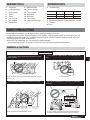
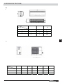
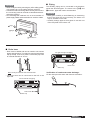
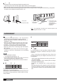
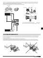
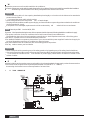
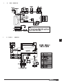
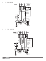
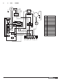
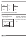
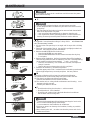
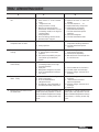
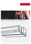
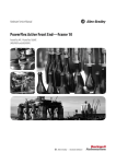
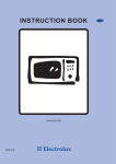
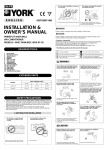
INSTALLATION MANUAL
Mini-Split Air Conditioner
TLCA/TLHA18-30OSAAA(D)R
Read this manual before installation and operation
Make sure that it is well kept for later reference
Read this manual before installation and operation
Make sure that it is well kept for later reference
CONTENTS
Safety precautions ......................................................................... 3
Part names ......................................................................................... 4
Manual operation ............................................................................ 5
How the air conditioner works .................................................. 5
Optimal operation ....................................................................... 6
Outdoor & Indoor Unit Dimension.......................................... 7
Installation procedure ................................................................. 8
Maintenance .................................................................................. 19
Operation tips .............................................................................. 20
P le a s e r e a d th is in s ta lla tio n
manual carefully before starting
the installation. It will tell you
necessary information.
Quality POLICY
We will continuously strive to sat is fy our c us tome rs with c ons is te nt
r e lia bility in produc t, s e rvic e a nd
support through superior qual ity, service culture and distinctive
technology.
2
ENGLISH
Troubleshooting guide ............................................................... 21
EXTENDED PARTS
REQUIRED TOOLS
1.
2.
3.
4.
5.
6.
7.
8.
crew driver
e agonal wrench
orque wrench
panner
eamer
ole core drill
ape measure
hermometer
9. Manifold guage
10. as lea detector
11. accum pump
12. Pipe clamp
13. Pipe cutter
14. lare tool set
15. lectrical circuit tester
1.
efrigerant Pipe
Models
18
24
30
iquid si e
1/4 inch
3/8 inch
3/8 inch
as si e
1/2 inch
5/8 inch
5/8 inch
2. Pipe Insulation Material Polyethylene foam mm thic
3. inyl tape
4. Putty
SAFETY PRECAUTIONS
Please read this installation manual carefully before starting installation of the unit.
his air conditioning system contains refrigerant under pressure, rotating parts and electrical connection which may
be dangerous and can cause in ury. Installation and maintenance of this air conditioning system should only be car
ried out by trained and quali ed personnel.
After unpac ing, please chec the unit carefully for possible damage.
efore underta ing any wor on the unit, ma e sure that the power supply has been disconnected.
-
WARNING & CAUTIONS
INSTALLATION
o not store or unpac the unit in a wet area or e pose
to rain or water.
It may cause the unit to short circuit and may result electric
shocks or re.
o not conduct installation in wet area or in the rain.
It is a high risk to cause the electrical shocks.
o not install in a place where ammable gas may
lea .
It may cause re.
his system is designed for domestic or residential
use only.
If used in certain environments, such as a manufacturing
workplace, the equipment may not function ef ciently.
ENGLISH
3
PART NA ES
INDOOR UNIT
3
INDOOR UNIT
2
Air inlet
1
2
3
4
5
6
7
1
ront panel frame
ront panel
Air lter
ori ontal air ow grille
ertical air ow louver
oom temperature sensor
isplay panel
A
C
lectrostatic
-
8 Infrared signal receiver
9
emote controller
10
rain hose, refrigerant
11
12
connecting pipe
onnective cable
top valve
iber ilter tandard
DISPLAY PANEL
4
5
Air outlet
6
1 AUTO
7 8
OUTDOOR UNIT
2
10
9
Air inlet
3
4
11
5
12
Air outlet
NOTE
DISPLAY PANEL
All the pictures in this manual are for e planation purpose
only. hey may be slightly di erent from the air conditioner
your purchased. he actual shape shall prevail.
NOTE
he display panel on the indoor unit would loo li e
one of following:
OPERATING TE PERATURE
Mode
emperature
oom temperature
1
2
3
4
5
utdoor
temperature
auto
ooling
operation
eating
operation
rying
operation
30
10
/1
18 -43
-15 -43 : or the
models with low
temperature
cooling system
21 -52
or special
tropical Models
/
Signal
receptor
his indicator illuminates when the air conditioner is in A
operation.
DEFROST
F C
&
his indicator illuminates when the air conditioner starts
defrosting automatically or when the warm air control feature
is activated in heating operation.
DIGITAL DISPLAY
isplays the current setting temperature when the air conditioner
is in operation.
OPERATION
his indicator ashes after power is on and illuminates when
the unit is in operation.
TI ER
his indicator illuminates when IM is set
/
.
11
-
24
43
21 52
or special
tropical
Models
CAUTIONS
1. If air conditioner is used outside of the above conditions,
certain safety protection features may come into operation
cause the unit to function abnormally.
2. oom relative humidity less than 80 . If the air conditioner
operates in e cess of this gure, the surface of the air conditioner
may attract condensation. Please set the vertical air ow
louver to its ma imum angle ertically to the oor , and set
I
fan mode.
3. ptimum performance will be achieved within these operating
temperature.
ENGLISH
MANUAL OPERATION
Manual operation can be used temporarily in case you can not nd the remote controller or its batteries are exhausted.
1
2
3
Manual control button
Open and lift the front panel up to an angle until it remains xed
with a clicking sound.
Push the button until the AUTO indicator is lit, the unit will work in
o
forced AUTO mode. (the default setting temperature is 24 C)
Close the panel rmly to its original position.
CAUTIONS
• Once you push the manual button, the operation mode is shifted in
an order as: AUTO, COOL, OFF.
• Push the manual button until the operation indicator ashes rapidly
( ve times per second), the unit now operating in forced COOL mode.
This is used for testing purposes only. On forced COOL mode, the
remote operation function is unavailable.
• When the OPERATION indicator goes o , the air conditioner is
OFF.
• To restore the remote controller operation, use the remote controller
directly.
Manual control button
HOW THE AIR CONDITIONER WORKS
AUTOMATIC OPERATION
operation starts
operation suppression zone
1
2
1 hours
Set temperature
2 hours
• When you set the air conditioner in AUTO mode, it will automatically
select cooling, heating (cooling/heating models only), or fan only
operation depending on what temperature you have selected and
the room temperature.
• The air conditioner will control room temperature automatically round
the temperature point set by you.
• If the AUTO mode is uncomfortable, you can select desired conditions
manually.
ECONOMIC OPERATION
ECONOMIC Operation
Cooling
Fan only
Cooling
Room
temperature
Fan only Cooling
Time
set temperature
DRYING operation
When you push SLEEP button during cooling, heating (cooling only
type without), or AUTO operation, the air conditioner will start following
operation. The fan speed will be automatically controlled. In the
operation suppression zone where capacity is kept to the minimum,
overcooling is prevented by raising the temperature setting by 1°C after
1 hour and by 2°C after 2 hours of operation. The room temperature
is thus regulated between the operation suppression zone and the set
temperature. (It depends on the outdoor temperature.)
DRYING OPERATION
• The dry mode will automatically select the drying operation based
on the di erence between the set temperature and the actual room
temperature.
• The temperature is regulated while dehumidifying by repeating turning
on and o of the cooling operation or fan only. The fan speed indicator
will display AUTO and low speed will be used.
ENGLISH
5
EN
OPTIMAL OPERATION
To achieve optimal performance, Please note the following:
• Ad ust the air ow direction correctly so that it is not directed on people.
• Ad ust the temperature to achieve the highest comfort level. o not ad ust the unit to excessive temperature levels.
• Close doors and windows on COOL or EAT modes, or performance may be reduced.
• Use TIMER ON button on the remote controller to select a time you want to start your air conditioner.
• o not put any ob ect near air inlet or air outlet, as the ef ciency of the air conditioner may be reduce and the air
conditioner may stop running.
• Clean the air lter periodically, otherwise cooling or heating performance may be reduced.
• o not operate unit with horizontal louver in closed position.
PREPARATION E ORE INSTALLATION
•
efore doing any work, check the interior power supply cord and the main breaker capacity are suf cient and the
installation area is suf cient and complies with the re uirements.
• Check that the power supply available agrees with name plate voltage.
• Electrical work, wiring and cables must be performed in compliance with national and local wiring codes and
standard.
• o not use the extension cables. In the case extended cables are needed, use the terminal block.
SELECTION O THE LOCATION
• Select a place which provides the space around the units as shown in the diagram below.
INDOOR
OUTDOOR
M
M
A
12 cm
12 cm
12 cm
230 cm
230 cm
230 cm
C
12 cm
12 cm
12 cm
D
15 cm
15 cm
15 cm
CAUTIONS
•
o not install in a place that cannot bear the weight of the unit.
ENGLISH
30 cm
30 cm
30 cm
200 cm
200 cm
200 cm
C
0 cm
0 cm
0 cm
D
30 cm
30 cm
30 cm
A
OUTDOOR UNIT PICTURES
D
I
Dimension
D
Mo el
1
2
2
1
1
1
221
1
1
221
EN
O
Dimension
Mo e
D
1
2
1
2
ENGLISH
PARTS INSTALLATION
Name of part
Installation plate
Mounting screw ST3.9x25 C
Clip anchor
Refrigerant Li uid side
pipe
as side
4
5
ty
1
8
8
o/ .35(18,000)
o/ 9.52(24000 30000)
o/ 12. (18,000)
o/19.05(24000 30000)
NOTE A
A
15cm or more
mo
rm
ore
1
2
Parts
you must
purchase
Remote controller
Remote controller holder
Seal
rain elbow
8
12c
12c
mo
1
1
1
1
Air
rm
ore
lter
Mounting screw
ST2.9x10 C
C
Remote controller
holder
The air conditioner can be connected only to a supply
with system impedance no more than 0.2 ohm. In case
necessary please consult your supply authority for system
impedance information.
Remote controller
Air blowing
direction
30 c
C
mo
0 c m or more
Part No.
1
2
3
r mo
e fore ins ta lla tion, ope ra te the re mote c ontrolle r to
determine its location in a reception range.
• eep the remote controller at least 1 m apart from the
nearest T set or stereo e uipment.
• o not install the remote controller in a place exposed to
direct sunlight or close to a heating source, such as a stove.
• Note that the positive and negative poles are right positions
when loading batteries.
re
re
r mo
mo
30 c
•
ore
200
cm
or m
0 cm
or m
ore
C
Loop the
connective
cable.
INSTALLATION PROCEDURE
INDOOR UNIT
• Place the installation guide pattern on the designated
installation place and mark the hole position.
• rill a hole and mount installation plate.
• Make mm 4 holes, in the wall at the four corners of mouting
plate (bracket) then insert appropriate mounting devices.
• Install the mounting plate using 4 pieces of mounting screw
securely at four corners and tighten the screw completely.
o not over tighten the screws and deform the back plate.
MODEL
150mm or mo re to c eiling
Installa tion plate
270
Indoor unit outline
Left re frigera nt
pipe hole 65
65
45
120mm or
more to wall
70
MODEL
/
16000Btu/h model)
150mm or more from the ceiling
1036
Hooked Part
Note: When installing
the refrigerant pipes from
others side. A hole must
be place to allow fall
towards the outdoor unit.
ENGLISH
Indoor
..
. .. .
.. .......
.
.. .. .. ..
.. ......... .
.
........ ..
.
..... .. .
.
.
.
. .. ..
.. ..
130
120mm or more
from the wall
130
65
65
50
50
. .. .. .
.. .. .. ..
.. .........
.
........ ..
.
..... ..
.
.. .. ..
. .
315
120mm or more
from the wall
138
380
22
380
After determining the pipe
hole position drill the hole
at a slight downward slant
towards the outdoor side.
Right r efrigerant
pipe hole 65
70
920
(
5 mm
120mm or
more to wall
Indoor Unit Outline
Outdoor
CAUTIONS
•
e careful when handling the sharp edge of the mounting
plate.
W
• This indoor unit is ready for connection to the outdoor unit.
■ Piping
CAUTIONS
• Never modify the unit by removing any of the safety guards
or by passing any of the safety interlock swithces.
• Connect the interconnecting cable correctly and connect
the connecting cable to terminal as identified with their
respective marking.
• Do not damage the conductor core or inner insulation of
power supply cables and do not deform or crush the cables.
The auxiliary piping can be connected in the diections
shown the above diagram. To connect in the ", # and
$ direction, pipes will need to be extended.
CAUTIONS
• Bend pipes carefully to avoid flattening or obstructing
them if the pipes are bent incorrectly, the indoor unit
may be unstable on the wall.
• Carefully arrange pipes so that pipes do not stick out
of the rear plate of the indoor unit.
Right
Right
Right
Left
Right
Rear Bottom
■ Drain hose
• Drain hose is flexible and can be routed to suit various
piping arrangements. The drain line must include elbow
trap (U bend). Connect a plastic condensate pipe with
an internal diameter of 12 mm.
For right and right rear piping
EN
Drain hose
Drain cap
.OTE$ONOTPUTTHEDRAINHOSEENDINTOWATER
• The drain hose can be connected to the left or the
right side.
Verification of condensate water drainage:
Fill the drain pan with water and observe evacuation.
For left and left rear piping
Drain hose
Drain cap
%.',)3(
9
I
•
•
•
•
U
Thread the indoor unit piping and cable through the hole.
ang the top of the unit onto the upper ridge of them in mounting plate.
Make sure that the unit is correctly hung in place by sliding it to the left, then to the right.
Press the bottom left and bottom right hand corners of the unit against the mounting plate until the xing prongs click
into place in the retainers provided to that e ect.
a
rainage line
Condensate
drainage line
Interconnection cable
Note:
a) Access plate for the
condensate drainage
pump detection
(condensate pump is
available as an
accessory).
inyl tape
he c onde ns a te e a c ua tion line s hould be ta pe d to the
refrigerant lines with in l tape.
OUTDOOR UNIT
R
P
• Piping must be performed by uali ed personnel
according to good refrigeration systems practices.
• Piping materials and insulation materials must be of
refrigerant uality.
• Select the pipe diameters according to the size of unit
and cut the pipe to design length by using pipe cutter.
• Install the are nuts and are the end of the pipes.
• Check that no foreign bodies are inside the piping.
• Align the central of the connecting pipes and tighten
the are nut.
• Fix piping with pipe clamps and check that any pipe
vibrations cannot be transmitted to the building
structure.
NOTE
• Connect the pipe correctly.
• o not apply the excessive tor ue.
• Use an appropriate bending tool to form curves and
avoid over tightening the refrigerant tubes.
• To prevent heat loss, the two lines must be insulated
separately.
M
P
L
U
15
20
20
The suction line must have a 2 gradient up to the
compressor on horizontal sections.
Where the di erence in elevation between the indoor unit
and outdoor unit is greater than 5 meter, install an oil trap
every 5 meters.
ENGLISH
MODEL
U
18
30
R
24
5
30
5
LARE
To avoid alteration of unit capacities, check that piping
lengths and changes in elevation are kept to a strict
minimum.
efore connecting the refrigerant lines, follow the
procedures below (if pre charged connection lines are
not supplied):
Select copper pipe diameters according to the size of
unit to be installed.
Install the refrigeration lines, checking that no foreign
bodies get inside the piping.
Install the are connectors and are the ends of the
pipes.
Evacuate the piping. This operation, which should last
at least 15 minutes if there are large piping lengths
and changes in elevation, should be followed by a leak
test.
To this e ect, when the piping has been evacuated, close the pressure gauge tap, note the value on the gauge, then
wait for 15 minutes. If the needle moves, there is a leak in the system. Make the necessary ad ustments or repairs
and repeat this procedure until the needle no longer moves.
Open the service valves and top up the refrigerant charge if necessary.
Insualation
Low pressure
igh pressure
Manifold
Minimum thickness
mm
eat pump
(discharge)
Li uid valve
Pressure tap
Outdoor Unit
eat pump
as Line
as valve
Indoor Unit
Li uid Line
Li uid
Cooling
Cooling
(suction)
R 22
eat pump
(discharge)
his unit is shipped complete with a charge of
refrigerant that
will be sucient for an interconnectiong piping length of meters.
eat pump
AS
Cooling
(suction)
Li uid
EN
Cooling
COLD AREA RECOMMENDATION
• Outdoor heat pump unit: install the unit at least 10 cm above ground level to facilitate drainage of defrost water and
prevent accumulation of ice. In e ect, defrost water can cause accumulation of ice under the unit during subfreezing
outdoor temperatures.
• In areas with heavy snowfall it is best to install the unit on wall supports.
• In some regions. It is necessary to heat the bottom of the condensate drainage pan and the condensate drainage pip
ing to avoid ice formation, and resulting ice build up in the fan compartment (heater strip must be at least 25 W/m).
OK
ENGLISH
W
Prepare the power source for exclusive with the air conditioner.
The supply voltage must comply with the rated voltage of the air conditioner: The plug socket shall be accessible after installation.
R
All the wiring must be based on the wiring nameplate which shown on the model.
CAUTIONS
• Perform the wiring with suf cient capacity. Installation places legally re uire a short circuit isolator to be attached to
prevent electrical shock.
• o not extend the power cable code by cutting.
• Power voltage should in the range of 90 110 of rated voltage.
• The plug of the air conditioner takes a grounding leg, so clients should use a grounding socket so that the air conditioner
can be grounded ef ciently.
ed technician or a serviceman.
• If the power cord is damaged, replacement should be conducted by uali
N
NOTE
Remark per EMC irective 89/33 /EEC
To prevent icker impressions during the start of the compressor (technical process), following installation conditions do apply.
1. The power connection for the air conditioner has to be done at the main power distribution.
The distribution has to be of an low impedance, normally the re uired impedance reaches at a 32 A fusing point.
2. No other e uipment has to be connected with this power line.
3. For detailed installation acceptance, please refer to your contract with the power supplier if restrictions do apply for
products like washing machines, air conditioner or electrical ovens.
4. For power details of the air conditioner, refer to the rating plate of the product.
5. For any uestion contact your local dealer.
C
CAUTIONS
• Never modify the unit by removing any of the safety guards or by bypassing any of the safety interlock swithces.
• Connect the connecting cable correctly and connect the connecting cable to terminal as identi ed with their respective marks.
• o not scratch the conductive core inner insulator of power supply cables and do not deform or smash on the
surface of cables.
E
C
All electrical wiring and connections must comply with local codes and standards. Power supply cord and interconnection
cord used must not be lighter than Polychloroprene sheeted cord (245 IEC 5 or 05RN F).
isconnecting device must have a contact separation of at least 3 mm.
I
U
TLCA
OSAAA D R
21
ENGLISH
I
U
TLHA
OSAAA D R
3
4
21
I
U
TLC H A
OSAA D R
EN
5
5
8
8
5
10
5
5
ENGLISH
O
U
TLCA
OSAA D R
TO INDOOR NIT
O TDOOR NIT
1 2N
RED
C
O ER O D
RE Y
This symbol
indicates
the element
is optional,
the actual
shape shall
prevail
C
C
C
E
R
COM RESSOR
YG
RED
FN
MOTOR
S
ITE
COM RESSOR
C CITOR
E
F N C CITOR
O
U
TLHA
OSAAA D R
TO INDOOR NIT
O TDOOR NIT
1 2N
E
RED
C
This symbol
indicates
the element
is optional,
the actual
shape shall
prevail
Y
E
O ER O D
RE Y
C
C
C
E
R
COM RESSOR
YG
S
ITE
COM RESSOR
C CITOR
RED
FN
MOTOR
E
F N C CITOR
ENGLISH
O
U
O
U
TLCA
TLCA
OSAADR
OSAAAR
3
3
3
4
ENGLISH
5
O
U
TLCA
OSAAAR
RED
M1
F N2
RED
RED
RED
E
ITE
C
ITE
C
TR NS1
1
C
O TDOOR NIT
S
COM
C
RED
CODE
NIT1
R
2
E
C
2
1 S1
RT
1
T2
2
C
1
C
C
C
COM RESSOR
C 1
COM RESSOR R N C
C 2
O TDOOR F N C
F N2
O TDOOR F N
T1
TERMIN
t2
MIDD E TERMIN
RT
M1
CN1
RED
RED
ITE
CT
CN
NIT1
CN
CN
U
TLHA
CN1 CN11
C SOC ETS
4
21
ENGLISH
C CONT CTOR
TR NSFORMER
OSAADR
3
I E TEM ER T RE SENSOR
TR NS1
RED
O
CONNECTORS
C RRENT IND CTOR
CN
CITOR
CITOR
CT
T1
C
RT N ME
O TDOOR CONTRO C
COM
1 S1
RED
CN11
IRING DI GR M
O
U
TLHA
OSAAAR
3
3
3
4
ENGLISH
E
W
M
P
12000 tu/h
I
S
R
A
S
50 z
10A /15A
220 230
0 z
1 A
220 240
50 z
220 240
or
/ 12000 tu/h
32A/25A
or
/ 21000 tu/h
220 230
0 z
NOTE
The supply voltage must be consistent with the rate voltage of the air conditioner.
D
A
1. Condition to start defrosting: Units will switch to defrosting
mode when either of the following conditions is met.
a. Unit has been running under T3 0
and T3 3 oC for 3 minutes.
o
C for 40 minutes
Starting efrosting Mode under condition a.
T3 (°C)
2
1
0
5
10
15 20
b. Unit has been running at high temperature protection
mode for 90 minutes. ( igh temperature protection
mode: when coil temperature of indoor unit reaches
55°C, outdoor unit will turn o external unit fan but
still keep compressor running).
25 30 35 40 45
0
50
2. Condition to stop defrosting: Units will switch back to
heating mode when either of the following conditions is
met.
a. Unit has been running at defrosting mode for 10
minutes.
b. T3 20 o C
Time
Elapsed
(min)
1
R
2
3
3 min
4
5
ENGLISH
40 min
eating mode
efrosting mode
T3 is coil temperature of outdoor units.
MAINTENANCE
WARNING
ousehol
Drain
Cleaner
No
It is necessary to stop the air conditioner and disconnect the power
supply before cleaning.
C
CAUTION
Thinner
• Use a dry cloth to wipe the indoor unit and remote controller.
• A cloth dampened with cold water may be used on the indoor unit if it
is very dirty.
• The front panel of the indoor unit can be removed and cleaned with
water. Then wipe it with a dry cloth.
• o not use a chemically treated cloth or duster to clean the unit.
• o not use benzine, thinner, polishing powder, or similar solvents for
cleaning. These may cause the plastic surface to crack or deform.
C
Filter Handle
ir reshening
ilter
1
A clogged air lter reduces the cooling ef ciency of this
unit. Please clean
the lter once every 2 weeks.
1. Lift the indoor unit panel up to an angle until it stops with a clicking
sound.
2. Take hold of the handle of the air lter and lift it up slightly to take it out
from the lter holder, then pull it downwards.
3. Remove the AIR FILTER from the indoor unit.
• Clean the AIR FILTER once two weeks.
• Clean the AIR FILTER with a vacuum cleaner or water, then dry it up
in cool place.
4. Remove the air freshening lter from its support frame (The installation
and removing method of the air freshening lter is di erent depending
on the models, see the pictures marked 1 and 2 on the left.)
• Clean the air freshening lter at least once a month, and replace it
every 4 5 months.
• Clean it with vacuum cleaner, then dry it in cool place.
5. Install the air freshening lter back into position.
. Insert the upper portion of air lter back into the unit taking care that the
left and right edges line up correctly and place lter into position.
M
ir reshening ilter
If you plan to idle the unit for a long time, perform the following:
(1) Operate the fan for about half a day to dry the inside of the unit.
(2) Stop the air conditioner and disconnect power.
Remove the batteries from the remote controller.
(3) The outdoor unit re uires periodic maintenance and cleaning. o not
attempt to do this yourself.
Contact your dealer or servicer.
C
2
• Check that the wiring is not broken o or disconnected.
• Check that the air lter is installed.
• Check if the air outlet or inlet is blocked after the air conditioner
has not been used for a long time.
CAUTION
•
o not touch the metal parts of the unit when removing the lter. In uries
can occur when handling sharp metal edges.
• o not use water to clean inside the air conditioner.
Exposure to water can destroy the insulation, leading to possible
electric shock.
• When cleaning the unit, rst make sure that the power and circuit
breaker are turned o .
ENGLISH
EN
OPERATION TIPS
The following events may occur during normal operation.
P
Compressor protection
• The compressor cannot restart for 3 minutes after it stops.
Anti cold air (Cooling and heating models only)
• The unit is designed not to blow cold air on EAT mode, when the indoor heat exchanger is in one of the following
three situations and the set temperature has not been reached.
A) When heating has ust starting.
) efrosting.
C) Low temperature heating.
• The indoor or outdoor fan stop running when defrosting (Cooling and heating models only).
efrosting (Cooling and heating models only)
• Frost may be generated on the outdoor unit during heat cycle when outdoor temperature is low and humidity is
high resulting in lower heating ef ciency of the air conditioner.
•
uring this condition air conditioner will stop heating operation and start defrosting automatically.
• The time to defrost may vary from 4 to 10 minutes according to the outdoor temperature and the amount of frost
buildup on the outdoor unit.
A
• A white mist may generate due to a large temperature di erence between air inlet and air outlet on COOL mode
in an indoor environment that has a high relative humidity.
• A white mist may generate due to moisture generated from defrosting process when the air conditioner restarts in
EAT mode operation after defrosting.
L
•
.
ou may hear a low hissing sound when the compressor is running or has ust stopped running.
This sound is the sound of the refrigerant owing or coming to a stop.
ou can also hear a low s ueak sound when the compressor is running or has ust stopped running. This is
•
caused by heat expansion and cold contraction of the plastic parts in the unit when the temperature is changing.
• A noise may be heard due to louver restoring to its original position when power is rst turned on.
D
This is a normal condition when the air conditioner has not been used for a long time or during
rst use of the unit.
A
This is caused by the indoor unit giving o smells permeated from building material, from furniture, or smoke.
T
AN
COOL HEAT
When indoor temperature reaches the temperature setting on air conditioner, the compressor will stop automatically,
and the air conditioner turns to FAN only mode. The compressor will start again when the indoor temperature rises
on COOL mode or falls on EAT mode (For cooling and heating models only) to the set point.
ripping water may generate on the surface of the indoor unit when cooling in a high relatively humidity (relative
humidity higher than 80 ). Ad ust the horizontal louver to the maximum air outlet position and select I fan speed.
H
The air conditioner draws in heat from the outdoor unit and releases it via the indoor unit during heating operation.
heat
When the outdoor temperature falls, heat drawn in by the air conditioner decreases accordingly. At the same time,
loading of the air conditioner increases due to larger di erence between indoor and outdoor temperature. If a comfortable
temperature cannot be achieved by the air conditioner, we suggest you use a supplementary heating device.
A
Power failure during operation will stop the unit completely.
For the unit without Auto restart feature, when the power restores, the OPERATION indicator on the indoor unit
starts ashing. To restart the operation, push the ON/OFF button on the remote controller. For the unit with Auto
restart feature, when the power restores, the unit restarts automatically with all the previous settings preserved by
the memory function.
L
isconnect the unit with power and then re connect the unit with power again. Push the ON/OFF button on the
remote controller to restart operation.
ENGLISH
TROU LESHOOTING GUIDE
P
P
R
A. The air conditioner does not
run.
1. Power failure.
2. Fuse blown or circuit breaker
open.
3. oltage is too low.
4. Faulty contactor or relay.
5. Electrical connections loose.
. Thermostat ad ustment too low
(in heating mode) or too high (in
cooling mode).
. Faulty capacitor.
8. Incorrect wiring, terminal loose.
9. Pressure switch tripped.
1. Wait for power resume.
2. Replace the fuse or reset the
breaker.
3. Find the cause and
x it.
4. Replace the faulty component.
5. Retighten the connection.
. Check thermostat setting.
. Find the cause then replace
capacitor.
8. Check and retighten.
9. Find the cause before reset.
. The outdoor fan runs but the
compressor will not start.
1. Motor winding cut or grounded.
1. Check the wiring and the
compressor winding resistance.
2. Find the cause then replace
capacitor.
2. Faulty capacitor.
1. There is a gas leak.
2. Li uid and gas line insulated
together.
3. The room was probably very hot
(cool) when you started the
system.
1. Remove charge, repair,
evacuate and recharge.
2. Insulate them separately.
3. Wait while unit has enough time
to cool the room.
1. Thermostat ad ustment too low
(in heating mode) or too high
(in cooling mode).
2. Faulty fan.
3. Refrigerant charge too low, leak.
4. Air or incondensables in refriger
ant circuit.
1. Check thermostat setting.
E. The compressor starts but shuts
down uickly.
1. Too much or too little refrigerant.
2. Faulty compressor.
3. Air or incondensables in
refrigerant circuit.
4. Changeover valve damaged or
blocked open (heat pump unit).
1. Remove charge, evacuate and
recharge.
2. etermine the cause and
replace compressor.
3. Remove charge, evacuate and
recharge.
4. Replace it.
F. Clicking sound is heard from the
air conditioner.
In heating or cooling operation any
plastic parts may expand or shrink
due to a sudden temperature change
in this event, a clicking sound may
occur.
In heating or cooling operation any
plastic parts may expand or shrink
due to a sudden temperature change
in this event, a clicking sound may
occur.
C. There is insuf
cooling.
cient heating or
. The compressor runs
continuously.
2. Check condenser air circulation.
3. Find leak, repair and recharge.
4. Remove charge, evacuate and
recharge.
ENGLISH
INSTALLATION REMO AL AND DISPOSAL
T
A
R
M
R
U
1. Isolate all sources of electrical supply to the unit including any control system supplies switched by the unit. Ensure that all points of electrical and
gas isolation are secured in the OFF position. The supply cables and gas pipework may then be disconnected and removed. For points of
connection refer to unit installation instructions.
2. Remove all refrigerant from each system of the unit into a suitable container using a refrigerant reclaim or recovery unit. This refrigerant may then
be reused, if appropriate, or returned to the manufacturer for disposal.
U
N
Where appropriate, drain the refrigerant oil from each system into a suitable container and dispose of according to local laws and regulations
governing disposal of oily wastes.
3. Packaged unit can generally be removed in one piece after disconnection as above. Any xing down bolts should be removed and then unit lifted
from position using the points provided and e uipment of ade uate lifting capacity. Reference MUST be made to the unit installation instructions
for unit weight and correct methods of lifting. Note that any residual or spilt refrigerant oil should be mopped up and disposed of as described above.
4. After removal from position the unit parts may be disposed of according to local laws and regulations.
2008 Johnson Controls, Inc.
www.johnsoncontrols.com
Form No.035M000349-003
Johnson Controls reserve the right to change product features without prior notice.