1
INSTALLATION MAN UAL
Split Duct Ceiling Air Conditioner
Thank you very much for purchasing our air conditioner,
Before using your air conditioner , please read this manual carefully and keep it for future reference.
2020001A1702
Please conduct in accordance with “Trial Run Tenor Nameplate”
on the electric control box.
When you start the air conditioner immediately after connecting
the power supply, or restarting the air conditioner after shutting it
down, the air conditioner is protected, and the compressor will be
started 3 minutes later.
CAUTION
1. Perform the trial run only after the outdoor unit has been
powered on for over 12 hours.
2. Check that all valves are opened before trial run.
3. Check the electric safety before trial run.
4. Do not perform compulsory operation in any way.(It is very
dangerous if the protection device is not active)
14.5 Refrigerant leak precautions
This air conditioner uses refrigerant R22. The R22 is safe refrigerant
which is harmless and non-flammable.
The room for placing the air conditioner should have a proper space.
Even if refrigerant leakage occurs, the density threshold will not be
crossed. Additional measures may also be taken.
threshold: Density of the Freon gas not harmful to
[ Density
]
human body. Density threshold of R22: 0.3 [kg/m ]
3
14.1. Perform trial run only after all installations are finished.
14.2. Confirm the following issues before trial operation, and
the box for the confirmed items.
Check whether the indoor unit and the outdoor are
installed properly.
Check whether the piping and wiring are correct.
Check whether the refrigerant pipeline system is
inspected for leakage.
Check the density threshold in the following sequence, and take the
corresponding measures.
1. Calculate the quantity of refrigerant to be replenished (A [kg])
Total refrigerant quantity = refrigerant replenishment quantity upon
shipment (12[kg]) + additional refrigerant replenishment
corresponding to the pipe length
2. Calculate out the indoor volume (B[ m3 ]) (according to the
minimum volume)
3. Calculate out the refrigerant density
A [kg]
Check whether the drain is smooth.
B [m3]
Check whether the heat insulation is perfect.
PAGE
CONTENTS
NOTE :
14. TRIAL RUN
2. INSTALLING SITE
1. PRECAUTIONS.......................................................................................1
2. INSTALLING SITE...................................................................................1
3. ACCESSORY(INDOOR UNIT)..................................................................1
4. INSTALLING THE INDOOR UNIT.............................................................2
5. INSTALLING THE OUTDOOR UNIT..........................................................3
6. INSTALL THE CONNECTIVE PIPE...........................................................6
7. AIRTIGHT TEST......................................................................................6
8. PIPING THERMAL INSULATION.............................................................6
9. EXPELLING AIR.....................................................................................7
10. INSTALL THE DRAIN PIPE...................................................................8
11. ELECTRIC CONNECTION......................................................................8
12. METHODS OF CONFIGURING AND SELECTING INSTALLATION..........10
13. CONSTRUCTION AND VENTILATION PIPELINE DESIGN SCHEME.......11
14. TRIAL RUN.........................................................................................12
1. PRECAUTIONS
3
≤ Density threshold: 0.3 [kg/m ]
Outdoor unit
Check whether the ground cables are connected
correctly.
Check whether the pipe length and the refrigerant
amount are recorded.
Read this user manual carefully before installing the equipment.
The air conditioner must be installed by professional technicians.
When installing the indoor unit and its accessory pipes, adhere to
this user’s manual as far as possible.
Inspect and make sure the piping and cabling are correct before
pair conditioner.
This information may change with the update of this machine, and
no further notice will be given for such change.
CAUTION
Check whether any obstacles exist at the air
inlet/outlet of the indoor or outdoor unit.
Room in which refrigerant is leaked
(All refrigerant is leaked)
Open the gas valve and the liquid valve.
Figure 35
Connect the power supply to preheat the air
conditioner.
14.4. Trial run
Use the remote controller or wire controller (matched) to let the air
conditioner run in the cooling mode. Inspect the following items
against the operation manual. (If any fault occurs, remove the fault
by reference to the Section headed “Faults of Air Conditioner and
Causes” in the Operation Manual.)
Measures against crossing of the refrigerant density threshold
1. In order to decrease the refrigerant density and keep it within the
density threshold, please install a mechanic ventilation device.
(keep ventilating)
2. In case frequent ventilation is impossible, please install the
leakage detection alarm device linked with the mechanical
ventilation device.
Outdoor unit
(1) Check whether any vibration or abnormal sound occurs during
the operation.
(2) Check whether the air, noise and condensate generated by the
unit affect the neighbors.
(3) Check whether any refrigerant is leaked.
Installation manual
12
After installing the air conditioner properly, the installer shall
demonstrate how to use and maintain the air conditioner correctly
to the user, and then prompt the user to read the operation manual
and installation manual properly.
OUTDOOR UNIT
Install the unit where {enough space of installation and
maintenance is available.
Install the unit where the air inlet and air outlet are free from
obstacles and strong wind.
Install the unit in a dry and well ventilated place.
Install the unit where the bearing surface is level and can bear
weight of the unit, and is suitable for installing the unit horizontally
without increasing noise or vibration.
Install the unit where the operation noise and the expelling of air
do not affect neighbours.
Install the unit where no flammable gas is leaked.
Install the unit where it is convenient for pipe connection and
electric connection.
CAUTION
A. The site contains mineral oils such as sulfide gas.
B. Factories where the supply voltage fluctuates seriously.
C. Inside a car or cabin.
D. Place like kitchen where oil permeates.
E. Place where strong electromagnetic waves exist.
F. Place where flammable gases or materials exist.
G. Place where acid or alkali gases evaporate.
H. Other special environments.
WARNING
Practice shows that most problems of using the duct air conditioner
are caused by improper installation. Improper installation cannot
ensure normal operation of the air conditioning unit, and it is costly
to correct Φsuch problems. Therefore, attach importance to
installation.
3. ACCESSORY(INDOOR UNIT)
Indoor unit
(1) Check whether the switch of the remote controller or wire
controller is normal.
(2) Check whether the functional keys of the remote controller or
wire controller are normal.
(3) Check whether the indoor temperature conditioning is normal.
(4) Check whether the indicators illuminate normally.
(5) Check whether the manual operation buttons are normal.
(6) Check whether the drain function is normal.
(7) Check whether the connective copper pipes and the drain pipes
generate condensate due to loose wrapping.
(8) Open the air inlet grille to check whether any penetration or leak
of water occurs, especially at the drain stopper.
(9) Check whether any vibration or abnormal sound occurs during
the operation.
(10) Test whether the unit works normally in the heating mode.
Install the unit where enough space of installation and
maintenance is available.
Install the unit where the ceiling is horizontal and enough for
bearing the weight of the indoor unit.
Install the unit where the air inlet and outlet are not baffled and are
the least affected by external air.
Install the unit where the supply air flow can be sent to all parts in
the room.
Install the unit where it is easy to lead out the connective pipe and
the drain pipe.
Install the unit where no heat is emitted from a heat source directly.
Installing the equipment in any of the following places may lead to
faults of the equipment (if that is inevitable, consult the supplier):
Check whether the supply voltage is equal to the
rated voltage of the air conditioner.
14.3. Install the remote controller holder as required by the user.
The holder must be installed in a location suitable for transmitting
the signals of the remote controller to the indoor unit.
INDOOR UNIT
Precautions before installation:
Decide the correct way of conveying the equipment.
Try to transport this equipment with the original package.
If the air conditioner needs to be installed on a metal part of the
building, electric insulation must be performed, and the installation
must meet the relevant technical standards of electric devices.
Note: If in the wire control mode, the accessories do not include display panel assembly remote controller or mounting bracket.
Accessory name
Indoor unit
OA
a. Ventilation orifice part
(The leakage detection alarm device should be installed at the place
vulnerable to retention of the refrigerant)
Quantity
Midea Commercial Air
Conditioner User Service Guide
1
OWNER’S MANUAL
1
Installation Manual
1
Throttling assembly
Shape
Purpose
(must be delivered to the customer)
This user manual
2
Connection system
Drip pipe
1
Connect to the drain pipe
Display panel subassembly
1
Receive remote controller signal
Sheath of refrigerant lead-in/lead-out pipes
4
Remote controller
1
7# battery
2
Figure 36
Installation manual
1
Precautions of operating the remote controller:
Do not throw or slam the remote controller.
Operate the remote controller within the receiving scope of the indoor unit, and direct the transmitting part of the remote controller to the
receiver of the indoor unit.
The remote controller should be over 1m away from the television or sound box.
Do not place the remote controller at a moist place, near the heat sources such as stove, or expose it directly in the sunlight.
Ensure correct positive and negative poles when loading the batteries.
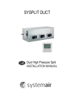
13. CONSTRUCTION AND VENTILATION PIPELINE DESIGN SCHEME
Examples of construction and ventilation pipeline design scheme
(Flowering hidden series)
4. INSTALLING THE INDOOR UNIT
4.1 Installation space
Over 500 mm
Ensure enough space required for installation and maintenance.
Maintenance space
Note: Ensure that the minimum
drain gradient is over 1/100.
600mmX600mm
Washroom
Inspection orifice
Inspection orifice
Figure 1
Document reference room
Computer room
Corridor
Over 600 mm
Warehouse
Figure 2
4.2 Install Φ10 pendant bolts or ground bolts
Meeting room
Office
739.5 mm
Office
1895mm
Construction and ventilation pipeline design scheme
Figure 3
1. Use Φ10 or bigger screws. The screw material is high-quality carbon steel (whose surface is zinc plated or undergoes other
rustproof treatment) or stainless steel.
2. The treatment of the ceiling varies between buildings. For detailed measures, consult with the fitting-out staff.
3. Fix the pendant bolts firmly and reliably in light of the specific situation.
4. Installation of the pendant bolt in different environments.
Kitchen
Wooden structure
New concrete roughcast
Put rectanglar sticks across the beams, and set pendant bolts.
Hall
Set it with embedded bushes or embedded bolts.
Wooden span
Lab
Retiring room
Meeting
room
Manager
office
Beam
Document room
Ceiling
Pendant bolt
Figure 4
Installation manual
2
( Blade plug-in unit)
( Slide plug-in unit)
Figure 5
Installation manual
11
Key points of duct connection
Old concrete roughcast
Use embedded bolts, embedded pulling plugs, and
embedded stick harness
Air outlet
Rectangular
Hose (for general purpose)
1. For purpose of air outlet.
2. Must adopt fire-resistant
materials. (Those materials other
than specified by Midea shall not
be applied)
3. The heat insulation material must
be glass wool.
3
10
Round
4
Air outlet noise pipe
5
Distributor
6
Rectangular Air outlet
7
Installation manual
10
11. Install the unit at the air inlet so
that the air flows smoothly and the
noise is lower.
2. The noise value varies with the
length.
3. The hose joint should be bent lest
detachment of the pipe.
1. Install the unit at the air outlet so
that the air flows smoothly and the
noise is lower.
2. The noise value varies with the
length.
3. The hose joint should be bent lest
detachment of the pipe.
1. Install the unit at a diffuser so
that the air flows smoothly and the
noise is lower.
2. Select 1BY2 or 1BY3 according
to the quantity of the diffusers.
3. The diffuser pipes should
preferably have the same length
after branching, and the minimum
length of the ventilation pipes is 5m.
1. Fixed model that diffuses air at
a 360 angle.
2. The outline size should increase
when the air volume is over
350CMH. (for above 303), i.e.,
when about 9 diffusers are
required, the outline size should
increase.
3. The diffuser pipes should
preferably have the same length
after branching, and the minimum
length of the ventilation pipes is 5m.
Linear diffuser
11
Air outlet wooden grille
12
Duct wrapping tape
Auxiliary materials
Air inlet noise pipe
1. Low noise compared with other
air outlets. Applicable to tall
buildings that require a long
distance of air conditioning.
2. Select the ventilation pipe
connection calibre according to the
distance and the air speed.
3. Applicable to storey height of over
5m (for design of tall storeys such
as temple, consult Midea).
1. The fan is the adjustable type
which can change direction of air
flow. It is used for deluxe decoration.
2. The outline size should increase
when the air volume is over
450CMH. (3 or 4SOLT) When about
6 diffusers are required, the outline
size should increase.
3. If the proper air speed is 2.5 5m/s
and actual air speed reaches over
5m/s, it is necessary to choose other
diffusers (with higher noise values).
Steel beam and girder structure
Set and use supportive angle steel.
360
330
300
Suspended bolt
Pendant bolt
Supportive
Figure 7
Air outlet duct connection screw hole location diagram
4.3 Suspending the indoor unit
Aluminium adhesive
tape
Figure 10
Use a hoisting device to hoist the indoor unit, align it with
the installation screw, adjust the horizontality and then tighten it.
1828
1655
Pendant bolt
Unit body
Figure 8
4.4 Design and connection of duct
1. It is used to prevent glass wool
leak and seal the gas at the time of
connecting the flanges and
pipelines of the ventilation pipes.
2. Entwine for over 3 circles.
3. Use ventilation pipe-specific
tapes (instead of ordinary adhesive
tapes).
In order to ensure the installation
quality and durability, it is necessary
to use auxiliary materials of standard
specifications provided by Midea
Electronics and the auxiliary
products of the specified
manufacturers.
540
540
angle steel
1. Low noise compared with other
air outlets. Applicable to tall
buildings that require a long distance
of air conditioning.
2. Select the ventilation pipe
connection calibre according to the
distance and the air speed.
3. Applicable to storey height of over
5m (for design of tall storeys such
as temple, consult Midea).
1. Flanges and pipelines connected
to the ventilation pipes.
2. When the noise pipe is connected
with the hose, the ventilation pipe
tape must be applied (otherwise,
with only adhesive tape, the
adhesion will be weakened due to
change of temperature).
1828
150
9
1 The lengthwise adjustable model
which diffuses air at a 360 angle.
2. With the change of the cooling/
heating air flow, the horizontal and
vertical distance of the fan can be
adjusted (applicable to department
store and exhibition hall where the
decorative effect is essential).
Prepare the assemblies other than air conditioner gas on the site.
136
2
Air outlet
NOTE :
Figure 6
563
1. For purpose of air inlet.
2. Must adopt fire-resistant
materials. (Those materials other
than specified by Midea shall not
be applied)
3. The heat insulation material must
be glass wool.
Figure 9
(Pipe pendant embedded bolt)
638
Filter
Hose (for absorbing noise)
Air inlet
Air filter
350
8
Embedded bolt
Air outlet
Noise
Inspection
suppression room
orifice
180
Air outlet
360 angle.
2. The outline size should increase
when the air volume is over
350CMH. (for above 303), i.e., When
about 9 diffusers are required, the
outline size should increase.
3. Proper air speed: For air speed of
over 2-3.5m/s, select other diffusers
(with greater noise).
4. Install the diffuser pipe if it is
necessary to install the model of
over 3.5m/s.
5. For purpose of cooling-only model
638
1
1. Install the filter at the main body grille
in case the storey height is low, and at
the main body of the indoor unit in case
the storey height is high.
2. It cleans conveniently at the time
of installing/uninstalling the filter.
3. The button structure is easy to
install and uninstall.
Steel bar
210
Air inlet wooden grille
Material name
144
Material name
Canvas adapter
Noise suppression room
Characteristics,
advantages and
other contents
1. Fixed model that diffuses air at a
Not less than 30
Characteristics,
advantages and
other contents
Canvas adapter
1. The duct design must comply with the national heating air
conditioner pipeline design specifications.
2. The accessories and materials must be produced by
professional manufacturers.
3. In order to prevent air flow shorting, do not keep the air inlet
pipe near the air outlet pipe.
4. Install a filter at an easy-to-maintain place such as intake pipe.
(Otherwise, the duct will gather on the air heat exchanger and
lead to
fault and water leak of the air conditioner.)
5. In order to suppress noise effectively, install noise suppression
and sound insulation devices, especially in the noise-sensitive
spaces
such as meeting rooms.
6. For connection of the flange plane, use non-flammable canvas
adapter to prevent transmission of vibration. For its size, see the
indoor
unit outline diagram. Use M6X20 screws (configured on site)
for connection.
7. All pipelines must be connected closely and soundly without
leak of air. The pipelines must be adiabatic and free from
condensation.
213
315
315
214
315
315
65
12. METHODS OF CONFIGURING AND SELECTING INSTALLATION
Return air duct rivet screw hole location diagram
Figure 11
5. INSTALLING THE OUTDOOR UNIT
5.1 Construction checkpoints
5.1.1. Installation
Check the model and name to avoid mistaken installation.
5.1.2. Refrigerant pipe
The refrigerant pipes must have the specified diameter.
Nitrogen of a certain pressure must be filled into the refrigerant pipe
before welding.
The refrigerant pipe must undergo heat insulation treatment.
After the refrigerant pipe is installed completely, the indoor unit
cannot be powered on before performing the airtight test and
creating a vacuum.
5.1.3. Airtight test
The refrigerant pipe must undergo the airtight test [with 2.94MPa
(30kgf/cm2G) nitrogen].
5.1.4. Creating a vacuum
Be sure to use the vacuum pump to create a vacuum of the
connective pipe at both air side and liquid side concurrently.
5.1.5. Refrigerant replenishment
If the pipe is longer than the reference pipe, the refrigerant
replenishment quantity for each outdoor unit should be calculated
through the formula obtained according to the actual length of the
pipe.
Installation manual
3
550mm
550mm
822mm
Indoor Unit
Snow protection facilities must be installed in the snowfall areas.
(See the figure) (in case the snow protection facilities are incomplete,
faults may occur). In order to prevent influence caused by snow, set
up raised pavilion, and install snow protection sheds at the air inlet
and11.0 air outlet.
>20 mm
<500mm
>20 mm
<500mm
Over 1000 mm
rear
ipe)
left p
5.3. Conveying outdoor unit
pipe
ip e
left p
B2
B1
A2
A3
A4
Power supply:
220V ~50Hz
5-cord cable
B
C
N
YCW-450/750 5*9mm
2
Power supply:
380-415V 3N~50Hz
NOTE :
Panel for
maintenance
right
RVV-300/500 3*2.5mm2
M6
M4
pipe
B3
B4
Bottom plane
for piping
and wiring
Bottom
plane
1. In case any obstacles exist above the outdoor unit, such
obstacles must be 2000mm above the outdoor unit.
2. If miscellaneous articles are piled around the outdoor unit,
such articles must be 400mm below the top of the outdoor unit.
2
A1
Figure 16
5.4.1. The refrigerant pipe adapter is located inside the outdoor unit.
So remove the left front board first.(four M6 screws; one M4 screw)
5.4.2. The pipe can be connected from the front left lower side or the
bottom notch of the outdoor unit.
5.4.3. When the pipe is connected from the front side, the pipe can
be led out through the pipe & wire panel.
5.4.4. In case the pipe is connected from the bottom notch, install it
leftward, rightward or backward after leading it out.
5.4.5. When the pipe is led from the front, use a cover plate to seal
the bottom notch in order to prevent intrusion of dust or trash.
Top view of the outdoor unit (multiple units installed)
NOTE :
RVVP-300/300 5X0.5mm
3-cord cable
Over 1000 mm
Figure 13
5-cord shielded cable
A
Over 1000 mm
4-cord cable
2
5.4. Refrigerant pipe
Over 1000 mm
Fixed-rate wire
controller (option)
RVV-300/500 4*1.0mm
Snow protection
shed at the air inlet
F i gu re 12
A B C DE
Snow protection
shed at the air outlet
Snow protection
shed at the air inlet
(Air inlet)
Installation & maintenance surface
Display board
Figure 15
1. When installing the unit, leave a space for maintenance shown
in the following figure. Install the power supply at the side of the
outdoor unit. For installation procedure, see the relevant
installation manual.
2. Ensure enough space for installation and maintenance.(see
the following figure)
(Air outlet)
(Air inlet)
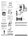
11.4 Electric wiring diagram
1288mm
Outdoor unit
5.2. Installation space
The distance of the foundation bolt is shown in the following figure.
792mm
Record the refrigerant replenishment quantity, actual length of
pipe and the height difference of the indoor & outdoor units onto
the operation confirmation table (on the electric control box) of
the outdoor unit in advance for future reference.
5.1.6. Electric wiring
Select the power supply capacity and wire size according to the
design manual. The power wire size of the air conditioner should
be greater than that of ordinary motors.
In order to prevent misoperation of the air conditioner, do not
interleave or entwine the power cable (380V 3N~ 50Hz) with the
connection wires (low-voltage wires) of the indoor/outdoor unit.
Power on the indoor unit after performing the airtight test and
making a vacuum.
5.1.7. Trial run
Perform the trial run only after the outdoor unit has been
powered on for over 12 hours.
right
pipe
1. Pay attention to the phase sequence of the power supply. If the phase sequence is reversed, the compressor will not start. Meanwhile, the
fault indicator of the outdoor electric control board will light up. For details, see Outdoor unit wring diagram on the cover plate of the
electric control box.
2. After shifting the phase sequence, power on the unit until the fault indicator goes out and the compressor starts up normally.
Figure 17
Cover plate
(prepared by the user)
5.3.1. Use 4 steel ropes of a Φ 6mm or bigger size to hoist the
outdoor unit and convey it into the room.
5.3.2. In order to prevent scratch and deformity the outdoor unit,
apply a guard board to the surface of contact between the steel
wire and the air conditioner.
5.3.3. Remove the cushion for use in the transport after finishing
the transport.
Steel wire
Bottom plane
Guard board
Figure 18
NOTE :
When welding the refrigerant pipe, in order to prevent internal
oxidation of the pipe, nitrogen must be filled in. Otherwise, the
oxidized chips may block refrigerating circulatory system.
Figure 14
The hole for fork truck
Installation manual
4
Base bracket
Installation manual
9
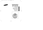
9.5 Procedure of using stop valve
Open the spool until it touches the stop block. Do not
attempt to open further.
Use a spanner or a similar tool to tighten the bonnet.
The bonnet tightening torque is shown in aboveTable
“Tightening torque”.
Upon completion of installation, open all valves before trial run.
Each unit has two valves of different sizes located at the
outdoor unit side. Of the two valves, one is gas valve and the
other is liquid valve. The procedure of opening/closing the
valve is shown in the right figure (Figure 29).
1) Procedure of opening the valve: Open the square-head
cover, use a spanner to capture the square head and open it
thoroughly. Then tighten the square-head cover.
2) Procedure of closing the valve: Same as the procedure of
opening the valve, but rotate the spanner clockwise
thoroughly.
9.6 Refrigerant charged volume
1. Refer to the nameplate of the unit for refrigerant volume,
provided that one way length of the pipe is no more than 5m.
2. Please refre to the following table for refrigerant volume,
provided that one way length of the pipe is longer than 5m.
NOTE :
5.4. Refrigerant pipe
Drain pipe trash gains easily at the drainage controller. Be sure to
install a stopper and a structure that cleans up trash easily.
10.2 Trial draining of the drain pipe
Open the side panel of the indoor unit, fill water inward, and check
whether the water can be drained smoothly. Check water leak at
the joint.
Liquid side piping diemeter
Φ16
0.19 kg/m×(L-5)
NOTE :
1. As per to the pipe circuit length for additional refrigerant,If the pipe
length is exceed to the sstandard length.
2. Please take note of the refrigerant charged volume perpare for
your future maintain and repair.
L---------Liquid side length (m)
10. INSTALL THE DRAIN PIPE
Inspection panel
Drain pipe
Inspection panel
over 100mm
10.1 Install the drain pipe of the indoor unit
In order to prevent drain overflow, install a drainage controller at
place 1 of the drain pipe. (The drainage controller is designed to
smoothen the drainage when the static pressure outside the unit is
high, especially at the air inlet, in addition to remove stink through
the drain pipe.)
The drain of water is natural. In the construction, the external pipe
of the outdoor unit slants downward at a gradient of 1/50~1/100.
The number of bends and folds of the drain pipe should not
exceed 2. Try to avoid bends in order to prevent trash accumulation.
In the construction, do not drop trash into the drip tray or drain
pipe of the indoor unit.
Upon completion of installing the drain pipe, remove the inspection
panel. Put water into the drip tray to check whether the water can
be drained levelly and steadily.
Indoor unit
capacity box
Noise mute box
(not encloused part, optional part)
10.3 Heat insulation of drain pipe
10.3.1. After making sure that the water drains smoothly and no
water is leaked, use adiabatic wool bushes to preserve heat of the
drain pipe. Otherwise, condensate will occur.
10.3.2. Ensure the thermal insulation material is coated on the
water drain pipe which part through inside of house.
10.3.3. Make sure the water drainage pipe be termal insulated.
11. ELECTRIC CONNECTION
11.1 Electric wiring
Air outlet duct
CAUTION
R22 additional refrigerant volume caculated method (Unit: kg):
Additional refrigerant volume is
equivalent to the length of piping
Air return duct
(not encloused part, optional part)
Water discharge vent
1. Use special power supply for the air conditioner. Design power
supplies specific to the indoor unit and outdoor unit. The supply
voltage must comply with the nominal voltage.
2. The external supply circuit of the air conditioner must have a
ground wire, and the power supply ground wire of the indoor unit
must be connected with the external ground wire firmly.
3. The wiring must be performed by professional technicians
according to the circuit diagram.
4. Distribute the wires according to the relevant electric technical
standards promulgated by the State, and set the Residual Current
-operated Circuit Breaker (RCCB) properly.
5. The power wire and the signal wire shall be laid out neatly and
properly, without mutual interference or contacting the connection
pipe or valve.
6. No power cable is attached to this equipment. The user can
select the power cable by reference to the stipulated power supply
specifications. No joint of wires is allowed.
7. Upon completion of wire connection, double check it and then
connect the power supply.
Main unit signal connective wire
between indoor unit and outdoor unit
Electric control box
Remote controller
(Refrigerant connective pipe)
Remote signal
receiving panel
Fix-rate wire controller
(not encloused part, optional part)
35 (Refrigerant connective pipe)
11.2 Specifications of power supply
INDOOR UNIT
Model
OUTDOOR UNIT
BSAH-150HR
Power
220-240V 50Hz
Switch capacity of the
main power supply/ fuse(A)
Indoor unit power cable
(mm2)
Includes grounded wire
Outdoor unit power cable
(mm2 )
Includes grounded wire
UCV-150HT
Outdoor unit
380-415V 3N~50Hz
40/20
60/50
RVV-300/500
2
3×2.5 mm
YCW-450/750
2
5×9 mm
RVV-300/500
2
4×1 mm
Connective wire between indoor
2
unit and outdoor unit (mm )
Wire controls
2
connective wire (mm )
RVVP-300/300
2
5×0.5 mm (Shielded wire)
Bush
(inspection and sweep orifice)
Main drain pipe
Figure 30
Control wire between
indoor unit and outdoor
unit
Outdoor unit
Bush
(inspection and sweep orifice)
over 50mm
11.3 Power wires
The power wires are as follows: (schematic diagram)
Electric control box of
outdoor unit
Indoor unit
RCCB Manual switch
Indoor unit power supply
220~240V ~50Hz
RCCB Manual switch
Outdoor unit power supply
Figure 19
380-415V 3N~50Hz
Figure 31
Installation manual
8
Installation manual
5
1. Measure the required length of the connective pipe, and make
the connective pipes in the following procedure.
1) Connect the indoor unit first, and then connect the outdoor unit.
The pipe bend should be handled carefully, without
damaging the pipe.
NOTE :
Before screwing up the flared nut, apply refrigerant oil at the
outer surface of the pipeline flare and the taper surface of the
connection nut. Screw up the nut for 3~4 circles beforehand
(see Figure 20).
When connecting or disconnecting the pipeline, be sure to use
two spanners concurrently.
Do not rest the weight of the connective pipe on the adapter of
the indoor unit. Too heavy load on the adapter of the indoor unit
may deform the pipe and thus affect the cooling/heating effect.
2) The valve of the outdoor unit should be closed completely (as in
the factory status). Every time when connecting the pipe, screw off
the nut at the valve, and connect the flared pipe (within 5 minutes).
If the nut is put away for a long time after being screwed off the
valve, dust and other foreign substance may intrude into the
pipeline system and lead to fault. Before connecting the pipe, use
the refrigerant (R-407C) to expel air out of the pipe.
3) After the refrigerant pipe is connected to the indoor and outdoor
units, expel air as instructed in the “Expel air” section. After
expelling the air, screw up the nut at the maintenance orifice.
A. Precautions for the flexible part of the pipeline
The bend angle shall not exceed 90°.
The bend shall be preferably in the middle of the pipe length,
and higher bend radiuses are preferred.
Do not bend the flexible pipe for over 3 times.
B. Bend the thin-wall connective pipe
When bending the pipe, cut out a notch of the desired size at
the bend of the adiabatic pipe, and then expose the pipe (wrap
the pipe with the wrapping tape after bending it).
The radio of the elbow pipe should be as large as possible to
prevent flattening or crush.
Use the pipe bender to make close elbow pipe.
7. AIRTIGHT TEST
Charge pressure nitrogen or R22 gaseous refrigerant for airtight
test after finish the connection procedure between indoor unit
and outdoor unit
NOTE :
1. Airtight test empoly aerocrete pressure[2.9MPa(30kg/cm 2G)].
2. Screw up the spools of high valve and low valve before
gas pressurization.
3. Pressure the gas from the ventilated orifice of low pressure
valve.
4. During the gas pressurization, please keep the high pressure
valve and low pressure valve in closed status.
5. Application of Oxygen, flammable gas or toxic gas for airtight
test are forbidden.
6. Please employ soapy water or leakagemeter for air leakage
detection of all junctions.
Installation manual
6
90
Slant
Coarse
Burr
Outdoor unit
NOTE :
1. Applicate normal thermal insolution materials, as well as additional
thermal insulation cotton, which thickness at least 10 mm
2
(16~20 kg/m ), for refrigerant piping and water drain tube thermal
insulation, provided that the ceiling temperature condition would be
in high (temperature)
and high humidity (Dew point temperature not
。
less than 23 C), (e.g, Inside the ceiliing which constructed by
moorstone, or the outdoor temperature is the same as the one
inside of the ceiling)
2. Please use heat resistant material for themal insulate material on
gas side piping.
3. Coat thermal insulation materials on liquid side and gas side
separately, more over, the gas side piping inside of the indoor unit
must be kept thermal insulation soundly, do not drip water outside
of the unit casing.
4. Please seal piping by ethylene resin band for prevent water
leakage after add axiliary thermal insualtion material into piping.
Air side
Apply refrigerant oil
D
Stop Valve
Liquid side
Figure 23
b.Pull the pipe into the rear flare of the connective nut.
Figure 24
Figure 27
8.4 Tighten the nut
Align with the connective pipe
Screw up the connection pipe nut manually, and use a spanner
to tighten it as shown in Figure 25.
Figure 25
Use a thumb to bend the pipe
NOTE :
Figure 21
Method of unleashing the spooled pipe.
Straighten the pipe end
Figure 23
8.2 Deploy the pipelines
8.2.1.1.Drill a porthole on the wall, and put the hole sheath and hole
cover through the wall.
8.2.1.2. Place the connective pipe together with the indoor & outdoor
connection wires. Use wrapping tape to tie them tight. Do not let air
penetrate into it lest condensation and drips of moist.
8.2.1.3. Pull the connective wrapped connective pipe from outdoor
through the sheath which gets through the wall, and lead it into the
room.Lay out the pipelines carefully lest damage to the pipes.
8.2.2. Make a vacuum of connective pipeline.
8.2.3. After the above steps are completed, the spool of the valve of
the outdoor unit should be completely open, and the refrigerant
pipeline of the indoor unit and the outdoor unit should be smooth.
8.2.4. Use a leak detector or soap water detect leak carefully to
prevent leakage.
8.2.5. Put on an adiabatic envelope (accessory) at connective pipe
adapter of the indoor unit, and wrap it tight with the wrapping tape
lest condensate and leakage.
Pipe adapter
Figure 26
Figure 20
Min. radius 100mm
C
B
8.1 Use purchased copper pipe
When the cooper pipe is purchased from the market, be sure to use
the heat insulation materials of the same type (with a thickness of
over 9mm).
Indoor unit
A
According to the installation conditions, too large torque will damage
the flaring, and too small torque will lead to looseness and leakage.
Determine the tightening torque by reference to the following table.
To external dime. Tighten torque N.m Additional tighten torque
N.m
24.5(2.5 kgf.m)
29.4(3.0 kgf.m)
Φ9.53
Φ12.7
49.0(5.0 kgf.m)
53.9(5.5 kgf.m)
Φ15.9
78.4(8.0 kgf.m)
98.0(10.0 kgf.m)
Φ19.0
98.0(10.0 kgf.m)
117.7(12.0 kgf.m)
9. EXPELLING AIR
9.1.From the following table, select a method of expelling air.
Length of connective pipe
(single pass)
Procedure of expelling air
9.3 Use refrigerant tank to expel air (see Figure 26 and Figure 27)
1. Screw up the pipe nuts at A, B, C and D completely.
2. Loosen and remove the square-head cover and the
maintenance orifice nut of valves A and B.
3. Connect the filler hose of the refrigerant tank with the
maintenance orifice of valve A.
4. Lon the valve of the refrigerant tank, continue filling
refrigerant for 6 seconds to expel the air, and tighten the nut of
valve B quickly.
5. Loosen the valve of the refrigerant tank again, and fill the
refrigerant for 6 seconds. Detect leak for all adapters at A, B, C
and D. After making sure that no leak exists, screw off the filler
hose. After all the filled refrigerant is expelled, screw up the
maintenance orifice nut of valve A quickly.
6. Open the square-head spools of valves A and B completely.
7. Tighten the square-head cover of valves A and B.
9.4 Use a vacuum pump to expel the air (Figure 28):
(For method of using the manifold valve, see the operation
manual of manifold valve)
1. Loosen and remove the maintenance orifice nut of valve A, and
connect the filler hose of the manifold valve to the maintenance
orifice of valve A (tighte n both valve A and valve B).
2. Connect the filler hose adapter to the vacuum pump.
3. Open the low pressure (Lo) handle of the manifold valve
completely.
4. Start the vacuum pump to extract air. At the beginning of
extracting air, slightly loosen the maintenance orifice nut of valve
B, check whether any air enters it (the vacuum pump noise
changes, and the multimeter indicates from negative to 0). Then
tighten this maintenance orifice nut.
5. Upon completion of vacuuming, tighten the low pressure (Lo)
handle of the manifold valve completely and stop the vacuum
pump. Keep extracting air for over 15 minutes. Check whether the
multimeter points at -1.0X10^5Pa(-76cmHg).
6. Loosen and remove the square-head cover of valves A and B.
After opening valves A and B completely, tighten the square-head
cover of valves A and B.
7. Remove the filler hose off the maintenance orifice of valve A,
and then tighten the nut.
Manifold valve
Less than 5m
5~15m
Use refrigerant in the outdoor unit
Use vacuum pump or refrigerant
tank.
9.2. Use the refrigerant in the outdoor unit to expel air (see Figure
26 and Figure 27)
1. Screw up the pipe nuts at A, B, C and D completely.
2. Loosen and remove the square-head cover of valves A and B,
rotate the square-head spool of valve B counterclockwise for 45
degrees and stay for about 10 seconds, and then close the spool
of valve B tightly.
Multimeter
manometer
-76cmHg
Lo-handle
Filler hose
Hi-handle
Filler hose
Lo pressure valve
Vacuum pump
Procedure of connecting pipes
a. Use a pipe cutter to cut off the pipe.
45+_2
In the process of installing the connective pipe, do not let the air,
dust or foreign substance intrude into the pipeline system.
Install the connective pipe only after fixing the indoor and outdoor
units.
Keep dry when installing the connective pipe. Do not let moist
intrude into the pipeline system.
Prevent malfunctions from condensation by refrigerant piping and
water drain tubes, please be sufficiently perform the condensate
prevention of thermal insulation operation.
A
Check the height difference between the indoor unit and the
outdoor unit, and check the length and number of bends of the
refrigerant pipeline, which must meet the following requirements:
Max. height difference............................................................20m
(If the height difference is greater than 5m, it is best to put the
outdoor unit above the indoor unit)
Max. pipeline length...............................................................50m
Max. number of bends...........................................................15
3. Detect leak for all adapters at A, B, C and D. After making sure
that no leak exists, open the maintenance orifice nut of valve A.
After all air is expelled, tighten the maintenance orifice nut of valve A.
4. Open the spools of valves A and B completely.
5. Tighten the square-head cover of valves A and B completely.
8.3 Flare
90+_4
6. INSTALL THE CONNECTIVE PIPE
8. PIPING THERMAL INSULATION
Figure 28
Installation manual
7