1
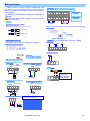
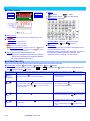
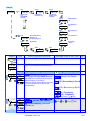
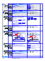
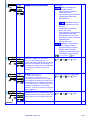
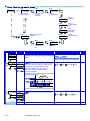
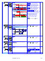
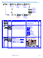
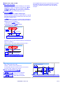
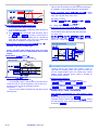
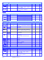
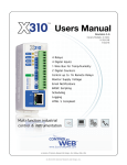
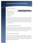
Programmable Meter CM1 User Manual ■ DESCRIPTIONS CM1 series Indicator has been designed in simple function and 4 digital 20.0mm LED displays with economic cost. They are can be programmed by tack switches that are hidden in backside of front bezel. They are also available 1 option of 2 Relay outputs, 1 Analogue output or 1 RS485(Modbus RTU Mode) interface with versatile functions such as control, alarm, re-transmission or communication for a wide range of industrial applications. ■ FEATURE Common Function ● Optional output available for one of 2 relay, analogue or RS485 ● Operation key built (in the front panel), can be set to display range;terminal straight into the design, no poor contact questions;installation depth of only 72mm ● CE CE Approved (EMC/EMI/LVD) & RoHS 【CM1-VA ECNOMIC VOLT/CURRENT Meter】 ● Measuring AC / DC Voltage 0~50.00mV/~600.0V / Current 0~1.999mA/~10.00A 【CM1-PR 4 Digital DC Process Meter】 ● Measuring DC voltage 0(1)~5V/~10V OR DC current 0(4)~20 mA/0~10 mA ● Purchasing power to stimulateadditional DC24V, 30mA 【CM1-RL 5 Digital RPM/Line speed Meter】 ● Measuring Frequency input 0.01Hz~6KHz,Do not need to specify the frequency range;Input Model(NPN、PNP、….) and Pulse level can be switch by DIP ● Optional excitation power DC12V, 30mA ■ APPLICATIONS ● CM1-VA High and low voltage power disk / motor control panel - Overload /mechanical voltage and ● ● current display / test equipment voltage / current display, alarm protection and computer connections CM1-PR Process in a variety of sensors (pressure transmitters, temperature and humidity transmitter ...) to do live shows,and computer alert to protect the connection CM1-RL Mechanical speed of the motor / speed limit on-sitedisplay, alarm protection and computer connections ■ ORDERING INFORMATION: Please confirm specifications prior to installation CM1−VA− DC/AC Input Signal − Optional Output − Aux. Powered OPTION CODE D A V1 V2 V3 V4 V5 V6 VA VB VC VO VOLT INPUT DC Input AC Input 0 ~ 199.9 mV 0 ~ 1.999 V 0 ~ 19.99 V 0 ~ 199.9 V 0 ~ 300.0 V 0 ~ 600.0 V 0~50 mV 0~60 mV 0~100 mV Specify V input CODE D A A2 A3 A4 A5 A6 A7 A8 AO CURRENT INPUT DC Input AC Input 0 ~ 1.999 mA 0 ~ 19.99 mA 0 ~ 199.9 mA 0 ~ 1.999 A 0 ~ 1.000 A 0 ~ 5.000 A 0 ~ 10.00 A Specify A input CM1-SERIES CODE OPTION OUTPUT None N R2 2 Relay I V 8 CODE AXU. POWER A AC 115/230V A2 AC 230V A/O: (0)4~20mA 0~10mA A/O: 0~10V (0)1~5V RS485(Modbus RTU) Relay, Analogue Output or RS485 Port can be selected one only 2012-11-08 1 / 27 Input CM1−PR− − − Output − Excit. Power AXU. POWER OPTION CODE A2 A3 A4 V4 V5 V6 Input signal range CODE OPTION OUTPUT None N R2 2 Relay 0 ~ 10mA 0 ~ 20mA 4 ~ 20mA 0 ~ 5V 0 ~ 10V 1 ~ 5V I A/O: (0)4~20mA 0~10mA V A/O: 0~10V (0)1~5V 8 RS 485 CODE EXCIT.Power N None E24 DC 24V EO Specify CODE A A2 AXU.Power AC 115/230V AC 230V Relay, Analogue Output or RS485 Port can be selected one only Input Model CM1−RL− Input Pulse − Output − Excit. Power − AXU. Power OPTION 1 CODE C 00 N P V 05 12 24 O xx Input Model Contact NPN PNP Voltage Pulse 5V Pulse 12V Pulse 24V Pulse Specify CODE N R1 I V 8 OPTION Output None 1 Relay A/O: (0)4~20mA / 0~10mA A/O: 0~10V / (0)1~5V RS485 Relay, Analogue Output or RS485 Port can be selected one only CODE EXCIT.Power E12 DC 12 V The excitation supply has to match the input mode. The standard is DC12V for 12Vp input mode only. AXU.Power CODE AC 115/230 V A AC 230V A2 ■ INSTALLATION Please check the specification, wire diagrams and functions on the label of the meter before installation.. DIMENSIONS & Panel Cut Out Front View ■ INSTALLATION 48.0 Kg/cn 60.0 96.0 8.0 12.0 PANEL CUT-OUT: 93+0.2(W) x 45+0.2(H) mm Panel Cut out 45.0+0.2 Dimension: 96mm x 48mm x 72mm Panel Cut out: 93mm x 45mm Unit: mm 93.0+0.2 2 / 27 CM1-SERIES 2012-11-08 FIX HOLDER: 63 mm(L) / W M3 1.0~8.0mm Wiring Diagram Please check the voltage of power supplied first, and then connect to the specified terminals. It is recommended that power supplied to the meter be protected by a fuse or circuit breaker.。 Remark,PT can not short in secondary;CT can not open in secondary Wiring may be changed, follow the wiring diagram on theinstrument wiring Terminals Terminals: 2 20A/600Vac, M3.5, 1.2~3.5mm (22~12AWG) 9 10 11 12 13 14 15 16 1 2 3 4 5 6 8 Power&Input Terminals AC115V AC230V AXU.Power Input Signal 20A/300Vac, M3.5, 12~22AWG; Max torque: 13Kg-cm 7 Option output terminal If power supply noise interference, install an isolation transformer.。 (If the use of electric driver, please adjust the torque electric driver) 7.0mm max 7.0mm max Input Signal Connection Output (one output available of Relay, Analogue or RS485) Connect the input signal, use twisted-pair isolation。 Relay output RELAY 1 b c a RELAY 2 b c a 9 10 11 12 13 14 15 16 Analogue Output CM1-PR Input Connection 2-wire sensor transmitter connection 4(0)~20mA Input Connection 24Vdc 4~20mA Input EXCIT.Power 1 2 3 9 10 11 12 24Vdc 4~20mA Input EXCIT.Power 4 5 1 2 3 RS485 port 4 5 A 9 10 11 12 4~20mA 3-wire sensor transmitter connection 1 2 3 Max. Distance: 1200M Terminate Resistor (at latest unit): 120~300ohm/0.25W (typical: 150ohm) 0~10V Input Connection EXCIT.Power 0~10V Input 4 5 1 2 24Vdc 0~10V Input B Vo 0V +V 24Vdc EXCIT.Power 3 4 5 0~10V Sensor Input Connrction DIP switch to switch the input mode and pulse level but must beconsistent with the input signal 3 0V +V +IN 1 2 +Vdc Out 0V DIP D-S NPN PNP CONTACT 1 2 3 ON ON ON Voltage pulse 5VP Voltage pulse 12VP Voltage pulse 24VP 4 5 ON ON ON DIP switch position cut to the bottom, behalf the DIP switch is ON CM1-SERIES 2012-11-08 3 / 27 ■ OPERATING ■ FRONT PANEL Relay status indication ● Stickers: Communication status indication COM RL1 R L2 L o Lo Action Lo. H Lo Action &Hold ● ● Unit stickers: 106 kinds H i Hi Action Hi. H Hi Action &Hold Engineer Unit Display screen ~A Number screen: ● : red high-brightness LED for 5 digital present value. Output LED: ● Relay Energized: 2 square red LED Operating Key: 4 keys for Enter(Function) / Shift(Escape) / Up key / Down key Pass Code: 4-digit password to set; To enter the parameter screen, you must enter the correct password, please remember the password. If youforget the password, please contact the company. This password can be in steps [Pcode] to change RL1 display when Relay 1 energized RL2 display when Relay 2 energized;; COM RS485 Communication: 1 square orange LED; COM will flash when the meter is receive or send data, and COM flash quickly means the data transient quicker.。 Stickers: Each instrument will be attached to the relay function areengineeringunits stickers and stickers ; Please choose according to site usage label affixed to the front panel functions and units。 ■ OPERATING KEY: *Please access to the Programming Level to check and set the parameters when users start to run the meter Operating Key: 4 keys for Enter(Function) / Shift(Escape) / The meter has designed operation similar as PC's and key means "escape( press Esc Up key / Enter Down key . In any page, press key means "enter" or "confirm setting", and )" or "shift". In Programming Level, the screen will return to Measuring Page after do not press any key over 2 minutes, or press Function Index (= ) Enter/Fun key (= ) Shift key (1) In any page, press to access the level or function index (2) From the function index to access setting status (1) In measuring page, press (2) In function index, press for 1 second to access user level. for 1 second to go back upper level. (3) In function group index, press for 1 second to go back for 1 second. Setting Status (3) Setting Confirmed, save to EEProm and go to next function index (4) In setting status, press to Shift the setting position. (5) In setting status, press for 1 second to abort setting and go back this function index. measuring page (= (1) In function index, press ) (1) In Function Index Page, press Up key (= Down key to select function to go back to previous function index (2) In setting status for function, press (3) During number Setting, press can roll the digit up ) will go to the next Function Index Page. (2) In setting status for function, press function (3) During number Setting, press down. 4 / 27 CM1-SERIES 2012-11-08 to select can roll the digit OPERATING DIAGRAM (The detail description of operation, please refer to operating manual.) Power ON . User Level 88888 0-01 Self-diagnosis 9999 cm!va Show the model number ver!0 Show the firmware version 9999 cm!va: Voltage and current cm!pr: 0~10V/4~20mA cm!rl: Speed / line speed Minimum value of PV saving Reset the saved value of Maximum & Minimum 0-07 1Sec 0-06 cm!va model of the meter firmware version Checking only 0-05 rYrst ry@sp Reset for energized Latch of Relay Relay 2 Set-point A-02 A-03 Programming Level 【CM1-VA/CM1-PR】 A-01 Pass Code Default:1000 pVdp input Decimal Point of PV Into A [Input group], the related parameter lOsc Low scale of PV hIsc High scale of PV A-04 lOcut group 1Sec A-05 relay group avg Into B [relay functional groups], the related parameter A-08 1Sec 1Sec ao group lnto D [analog output gr oup], the related parameter group A-07 Low Cut the PV Average update for PV A-06 Pcode Dfilt Mavg Pass Code setting for access to Programming Level Digital filter Moving Average update for PV A-01 A-02-1 A-02-2 【CM1-RL】 pVtyp input Select Display type line speed / rpm 1Sec rs485 Relay1 Set-point A. INPUT GROUP NO input Mrst max Maximum value of PV saving ry!sp 1Sec Escape User Leve enter 0-03 0-04 MEASURING PAGE Enter the password to access programming Level min 1Sec MEASURING PAGE 1Sec Access User Leve Pcode 0-02 ppr Input pulse ratio setting; Eunit Line Speed display units select Into E [RS485 functional groups], the related parameter A-02-3 diamt A-03 dp 1Sec A-10 1Sec Pcode A-04 Pass Code setting for access to Programming Level A-05 A-08 avg Display decimal point positio n select Ratio Factor factr A-09 Dfilt Shaft Diameter set lOcut Digital filter A-06 Average update for PV itOmd Display low cut Display set to zero A-07 ito CM1-SERIES 2012-11-08 Display zero time setting 5 / 27 B. RELAY GROUP B-01 relay rYsb Start band for Relay energized B-02 rYsd Start delay time for Relay energized B-03 ry!md Relay 1 energized mode B-04 ry!hy B-05 ry!rd B-06 ry!fd B-10 1Sec ry@fd A-09 ry@rd D.ANALOGUE OUTPUT GROUP D-01 ao aOtyp Analogue Output type selection B-07 Relay 2 de-energized delay time ry@md D-02 D-03 high point is relative to the highest of Analogue output aOzro 1Sec aOlmt Analogue Output High Limit (CM1-RL No this Fun.) D-06 D-05 ZSclr aOspn clear fine Zero / Span Adjustment for Analogue output Fine Span Adjustment for Analogue High Output E-02 E-03 E. RS485 GROUP E-01 rs485 adres Device number of the meter 1Sec 6 / 27 CM1-SERIES 2012-11-08 baud Baud rate Relay 2 energized mode aOhs D-04 D-07 Relay 1 de-energized delay time ry@hy Relay 2 Hysteresis low point is relative to the lowest of Analogue output Relay 1 energized delay time A-08 Relay 2 energized delay time aOls Relay 1 Hysteresis prity Parity Fine Zero Adjustment for Analogue Low Output OPERATING DIAGRAM (Into the User Level) 0-01 9999 0-03 min max Minimum value of PV saving Maximum value of PV saving 1Sec MEASURING PAGE 0-02 Mrst Reset the saved value of Maximum & Minimum 0-04 Relay1 Set-point ry!sp 0-07 1Sec 0-06 cm!va rYrst model of the meter firmware version Reset for 0-05 ry@sp Relay 2 Set-point energized Latch of Relay INDEX Step FUNCTION DESCRIPTION PARAMETERS & SETTING SET Please check the specification POWER ON ***** Self-diagnosis cm!va Model ver!0 Firmware version cm!va: Voltage / Current cm!pr: DC 0~10V/0~20mA cm!rl: RPM / Line speed 9999 Measuring Page Press 0−01 and wiring diagrams firstly. (LED All bright) for 1 second return to Measuring Page min (PV Minimum storage): the Minimum value of min Checking only PV saving When the meter power is turned on, both began to record shows )0 that the minimum value had occurred;Except by [Mrst] (step 0-03) to perform cleanupfunctions or instrument off; otherwise been recordedand stored automatically 0−02 update the new value. max max (PV Maximum storage): the Maximum value of 99(9 When the meter power is turned on, both began torecord shows Checking only PV saving that the maximum value has occurred;Except through [Mrst] (step 0-03) to perform cleanupfunctions or instrument off; otherwise will always be recorded and stored the new value is automatically 0−03 updated Mrst no no yes Mrst (Maximum & Minimum reset): Reset the Setting Range: saved value of Maximum & Minimum yes / yes(Yes): Clear the no Be stored maximum / minimum values, this functioncan stored maximum /mini be removed. This meter will be removedimmediately after mum value the relatively new storage maximum/ minimum values。 no(No): Does not clear the storedmaximum / minimu m values & Cycle selection Determine NEXT CM1-SERIES 2012-11-08 7 / 27 0−04 ry!sp ry!sp (Set-point of relay 1): Relay 1 10)0 Set-point Setting Range: -1999~9999 (CM1-RL:-19999~99999) Shift 10)0 Up Down Enter 10)9 0−05 99(9 ry@sp ry@sp (Set-point of relay 2): Relay 2 10)0 Set-point Setting Range: -1999~9999 (CM1-RL:-19999~99999) Shift 10)0 Up Down Enter 10)9 0−06 99(9 rYrst rYrst (Reset relay hold): Reset for no energized Latch of Relay Setting Range: NO/YES Shift Up Down Enter no 0−07 yes cm!va: model of the meter firmware version cm!va(CM1-VA): Voltage / Current cm!pr(CM1-PR): DC 0~10V/0~20mA cm!rl(CM1-RL): RPM / line speed ver!0(Ver 1.0): firmware version Cyclic to first page cm!va 0−01 ver!0 min Under the screen in any of the above )0 Checking only;The model number and softwareversion will differaccording to different models Press for 1 sec. back to Measuring Into the Programming Level INDEX Step FUNCTION DESCRIPTION 99(9 Measuring display enter Pass code screen 0000 PARAMETERS & SETTING To change the password set to Step A-8, and do not forget the password Pcode Default:1000 0000 1000 Pass Code Pass code input YES Press Into Programming Level 8 / 27 Press CM1-SERIES 1 Sec Can back to Measuring display 2012-11-08 SET Input parameter group CM1-VA/CM1-PR A-01 A-02 pVdp input Decimal Point of PV A-03 lOsc Low scale of PV hIsc High scale of PV A-04 Low Cut the PV lOcut A-05 Average update for PV avg A-08 1Sec A-07 Pcode Pass Code setting for access to Programming Level INDEX Step A-06 Dfilt Digital filter Mavg Moving Average update for PV FUNCTION DESCRIPTION PARAMETERS & SETTING SET Pass code input Pass Code YES input group Input function group promptscreen A−1 Any of the following screen Press pVdp pVdp(Decimal Point of PV): Decimal 0 1sec,back Input group Setting Range: 0/ Point of PV 0 & )0 / )00 / )000 Cycle selection Enter A−2 00)0 lOsc lOsc(Low scale): Low scale of PV 00)0 )0 Setting Range: -1999~9999 (CM1-RL:-19999~99999) Shift Up • • • • 00)0 [ lOsc] )00 )00 % A−3 Enter [ hIsc] 5)00 [ lOsc] 2%00 00)0 hIsc Down SCALE Default: [ lOsc]: )00, [ hIsc]: 5)00 [ hIsc] Changed: [ lOsc]: 2%00, [ hIsc]: 9(99 9(99 Negative Slope hIsc(High scale): High scale of PV 99(9 99(9 INPUT 5)00 % 10)00 % Setting Range: -1999~9999 (CM1-RL:-19999~99999) Shift Up Down Enter 99(0 • • • • 90)0 20)0 NEXT CM1-SERIES 2012-11-08 9 / 27 A−4 lOcut lOcut (Low Cut): Low Cut the PV 00)0 Low Cut set to be +0.50 00)0 [ lOcut] )50 Present Value )0 Shift PV according to input signal X1 0.50 -0.50 [ lOcut] -)10 Low cut function A−5 Low Cut is set for 0.50, if the PV is from -0.50~+0.50, that display will be 0. avg avg (Average): Average update for PV 5 5 09 09 -1999~9999 counts Up Down Enter Low Cut set to be -0.10 X1 00!0 Setting Range: The meter’s sampling is 15cycle/sec If the [ avg](Average) set to be 3 to express the display update with 5 times/sec. The meter will calculate the sampling 1-3 and update the display value. At meantime, the sampling 4-6 will be processed to calculate. Present Value PV according to input signal -0.10 X2 Low cut function Low Cut is set for -0.10, if the PV is under (< = -0.10), that display will be -0.10. Setting Range: Shift 1(NONE)~99 times Up Down Enter A−6 99 Mavg Mavg (Moving Average): Moving Average 8 8 09 09 update for PV Setting Range: Shift 1(NONE)~99 times Up Down Enter In the first updated display value will be same as average function. In the next updated display value, the function will get the new fourth sample (sample 4) then throw away the first sample (sample 1) that the newest 3 samples(sample 2,3,4) will be calculated for the updated display value. A−7 99 Dfilt Dfilt (Digital filter): Digital filter 08 8 09 09 A−8 99 Pcode The digital filter can reduce the influence of spark noise by magnetic of coil. If the values of samples are over digital filter band(fixed in firmware and about 5% of stable reading) 3 times (Digital Filter set to be 3) continuously, the meter will admit the samples and update the new reading. Otherwise, it will be as treat as a noise and skip the samples. Shift 1(NONE)~99 times Up Down Enter Pcode (Pass Code): Pass Code setting Setting Range: 0000~9999 1000 0000 for access to programming level Please remind and write down the new pass code so that access to programming level. 1009 • • • • 1999 9999 10 / 27 Setting Range: CM1-SERIES 2012-11-08 Shift Up Down Enter CM1-RL A-01 A-02-1 pVtyp input A-02-2 ppr Input Pulse precedes set; DisplayType Line speed/RPM Selection Eunit Line Speed Display units selection A-02-3 Shaft diameter set diamt A-03 Decimal Point set dp A-04 Ratio Factor of PV factr 1 秒 A-10 Pcode A-09 Pass Code setting foraccess to programming level A-05 Digital filter A-06 lOcut A-08 A-07 avg Average update for PV Step Zero mode setting itOmd Dfilt INDEX Low Cut the PV ito Zero tine setting FUNCTION DESCRIPTION PARAMETERS & SETTING SET Pass code input Pass Code YES input group Input function group promptscreen A−1 Any of the following screen Press pVtyp lNspd lNspd rpm 1sec,back Input group pVtyp (PV type selection): Setting Range: DisplayType Line speed/RPM Selection The meter has a measurement line speed, RPM and frequency functions. Users can simply set the display purposes, the meter will start the function of the corresponding。 lNspdLinearly Line Speed:; rpmRPM: Revolution(s) Per M inute rps(RPS): Revolution(s) Per S econds hz(Hz): Frequency khz(kHz): Frequency A−2−1 & ppr 1 pVtyp selected ( rpm / rps) / 1 (lNspd),the fun. will display ppr(Pulse/rotation): Input Pulse 99999 Cycle selection Setting Range: Shift Enter r 1~99999 Up Down Enter precedes set NEXT CM1-SERIES 2012-11-08 11 / 27 A−2−2 pVtyp selected (lNspd),the fun. Setting Range: m/mn: (M/min) m/mn will display m/mn Eunit(Engineer cm/mn: (CM/min) yd/mn Unit): Line speed display unit yd/mn: (Yd/min) selection ft/mn: (Ft/min) Eunit A−3 A−轉速 2−3 & Cycle selection Enter pVtyp selected (lNspd) ,the fun. Setting Range: 0.0001~9.9999M(公尺) )1000 will display )1000 diamt(Diemeter): Shaft diameter s Shift Up Down (9999 et diamt pVdp:Decimal Point of PV; 0 There are two definitions for 0 thissetting: )0000 1.If fun. setting is auto,the pVdp set pVdp Enter Setting Range: 0/ )0 / )00 / )000 / 0.0000 & Cycle selection Enter point for the relay output of decimal places set; 2.If fun. setting is semior manul,the A−4 pVdp set point for the relay output & PV of decimal places set; factr !000 factr(Factor): Display scale factor; !000 Setting Range: Display value = calculated value x scale factor Shift lOcut (Low Cut): Low Cut the PV Setting Range: 0.001~9.999 Up Down Enter A−5 (999 lOcut 0 00000 Low Cut setting +0.50 PV 值 00100 [ lOcut] )50 -19999~+29999 counts PV linear Shift Up Down Enter Low Cut setting -0.10 0.50 -0.50 PV值 Low Cut Function [lOcut]is setting 0.50,when PV between -0.50~+0.50,Display is “0”。 PV linear [ lOcut] -)10 -0.10 Low cut function A−6 [lOcut]is setting -0.10,PVLess than equal to (< = -0.10),Display is “-0.10”。 itOmd auto itOmd:Input Time Out Mode auto manul When the frequency is too low, this table shows the calculation based on this function to set the time zero value。 Setting Range: auto (Auto): Automatic calculation zero display timo。 manul (Manual): Manually calculation zero display timo。 A−7 & ito )0 itOmd selected manul,the Fun. )0 desplay ito(Input Time Out): Zero time %0 。 When the frequency is too low to setting display zero value(TIME OUT) time setting NEXT 12 / 27 CM1-SERIES 2012-11-08 Cycle selection Setting Range: Shift Enter 0.0 sec~999.9sec Up Down Enter A−8 range auto range:Display Range Mode auto Setting Range: auto(Auto): Automatically adjust the decimal point position;according to the size of the input frequency,automaticall y switching the decimal point position。 manul semi(Semi-Auto): Semi-a utomatic adjustment of the decimal pointposition; according to the size of the input frequency,automaticall y switching the decimal point position;but no more than set the value of decimal placesdecimal point position set。 manul(Manual): Fixed display range; display decimal point according to the set position when the input frequency exceedsfull scale, it will display ovfl overflow。 A−9 & avg 5 05 A−10 99 Dfilt 0 0000 A−11 The meter’s sampling is 15cycle/sec If the [ avg](Average) set to be 3 to express the display update with 5 times/sec. The meter will calculate the sampling 1-3 and update the display value. At meantime, the sampling 4-6 will be processed to calculate. Dfilt :Digital filter The digital filter 00 99 Pcode Cycle selection Enter avg (Average): Average update for PV Setting Range: 1(None)~99 times 1000 9999 Shift Up Down Enter Setting Range:0(None)/1~99 times can reduce the influence Shift Up Down Enter of spark noise by magnetic of coil. If the values of samples are over digital filter band(fixed in firmware and about 5% of stable reading) 3 times (Digital Filter set to be 3) continuously, the meter will admit the samples and update the new reading. Otherwise, it will be as treat as a noise and skip the samples. Pcode (Pass Code): Pass Code Setting Range: 0000~9999 setting for access to programming level Shift Up Down Enter Please remind and write down the new pass code so that access to programming level. CM1-SERIES 2012-11-08 13 / 27 Relay function parameter group B-01 (If you do not specify this function, this group will notappear related functions) B-02 rYsd rYsb relay B-03 Start band for Relay energized ry!md Start delay time for Relay energized Relay 1 energized mode B-04 ry!hy B-05 ry!rd B-06 ry!fd B-10 1秒 ry@fd B-07 Relay 2 de-energized delay time ry@md B-09 INDEX Step B−1 relay group rYsb )0 Relay 1 Hysteresis Relay 1 energized delay time Relay 1 de-energized delay time Relay 2 energized mode B-08 ry@rd ry@hy Relay 2 energized delay time ry@hy: Relay 2 Hysteresis FUNCTION DESCRIPTION PARAMETERS & SETTING Relay function group promptscr Any of the following screen Press 1 sec, een Back to Relay function group rYsb: Start band of Relay Output 00)0 99(9 When the value exceeds the action does not startwith, then the start-up delay time (Start delay time), the relay will start the PV value compared with theoutput setvalue S t a rt D e la y Setting Range: Shift 0~9999 counts Up Down Enter Inhibit Inhibit [ry_.sp] Hi Setting [ rYsb] Start Band Relay Energized Start delay time ON B−2 [ rYsd] rYsd )0)0 rYsd :Relay Output start delay )0)0 time Shift (5(9 NEXT 14 / 27 CM1-SERIES Setting Range: 2012-11-08 0:00.0~9m:59.9s Up Down Enter SET B−3 ry!md hi ry!md :Relay 1 energized mode hi hIhld Hi / Lo R e la y E n e rg i ze d [ry1.sp] [ry1.sp] [ry1.md] hi lo Hi lo(Low Level Energized): Low Level Energized;Relay will energize when PV <Set-Point. Low hi (High Level Energized): ON High Level Energized;Relay will energize when PV >Set-Point. ON ENERGIZED R e la y E n e rg i z e d L a t ch & Reset [ry1.md] hIhld B−4 [ dNkey] rYrst ry!hy )0 HI Hi. HLd(Hi Latch) relay energized Reset relay Latch by ECI or Front Key ON Level Trigger 50)0 Shift 0~5000 counts Up Down Enter [ry!hy] De-energized delay Energized delay Relay Energized B−5 Level energize andlatch; As the PV Higher (or lower) than set-point, the relay will be energized to latch except manual reset by from key in [User Level], front key function or terminals of E.C.I. closed & Cycle selection Enter [ry!sp] [ry!rd] )0)0 hIhld / lOhld (High / Low Level energized hold):High / Low Setting Range: Energized / De-energized Delay & Hysteresis Hi Setting ry!rd ON ry!hy:Relay 1 Hysteresis 00)0 off(Turn off the Relay):Turn off the Relay andindication LED. ENERGIZED [ry1.sp] Programmable: Hysteresis [ry!fd] ON ry!rd :Relay 1 energized delay )0)0 time Setting Range: Shift 0:00.0~9(m):59.9(s) Up Down Enter B−6 (5(9 ry!fd )0)0 ry!fd :Relay 1 de-e6nergized )0)0 delay time Setting Range: Shift 0:00.0~9(m):59.9(s) Up Down Enter B−7 (5(9 ry@md hi ry@md :Relay 2 energized mode hi Setting Range: the same as ry!md Off lo hi hIhld lOhld hIhld & Cycle selection Enter NEXT CM1-SERIES 2012-11-08 15 / 27 B−8 ry@hy )0 ry@hy:Relay 2 Hysteresis 00)0 B−9 )0)0 ry@rd :Relay 2 energized delay )0)0 time B−10 )0)0 Down Enter 0:00.0~9 分:59.9 秒 the same as ry@rd Up Down Enter ry@fd :Relay 2 de-energized delay Setting Range: 0:00.0~9 分:59.9 秒 )0)0 time the same as ry@fd Shift (5(9 16 / 27 Up Setting Range: Shift (5(9 ry@fd 0~5000 counts the same as ry@hy Shift 50)0 ry@rd Setting Range: CM1-SERIES 2012-11-08 Up Down Enter Analogue Output Group (The group will not be displayed except the AO function is to be specified ) D-01 D-02 aOls aOtyp ao D-03 aOhs Analogue Output type and the Low point is relative to the High point is relative to range selection; Analogue Output low; Analogue Output high; D-04 Fine Zero Adjustment forAnalog Low Output; Fine Span Adjustment forAnalog high Output; aOzro D-05 aOspn D-07 Analog Output High Limit (CM1-RLhasnot the Fun.) Step ao group ZSclr aOlmt 1Sec INDEX D-06 Clear the Fine Zero / Span Adjustment for Analog Output FUNCTION DESCRIPTION AO GRIOP INDEX PAGE PARAMETERS & SETTING In following pages, press SET for 1 second to return the AO D−1 GROUP INDEX PAGE. aOtyp A4-20 A4-20 V0-10 aOtyp :Analogue Output type Programmable: Analogue output type had been fixed in mA or V as customer ordering requested. Therefore, the type selection is only for the ranges in same type(Voltage or Current).。 Voltage Output: V0-10(0~10V) / V0-5(0~5V) / V1-5(1~5V) Current Output: A0-10(0~10mA) / A0-20(0~20mA) / A4-20(4~20mA) D−2 & aOls :Analogue Output relative 000)0 Low Scale Ex. Output range set to be A4-20 )0 50)0 (4~20mA) is relative to display 0~199.99;User can set the [aOls] (Ao.LS) to be 5)00,At aOls meantime, the output signal will be 4mA Cycle selection Setting Range: Enter -19999~29999 (CM1-RL:-19999~99999) Shift Up Down Enter Default: [ lOsc]: 0.00, [ hIsc]: 19(99; SCALE Changed: [ aOls]: 50.00(Relative Low), [ hIsc] [ aOhs]: 150.00 (Relative High) 19(99 [ aOhs] 15)00 10)00 [ aOls] 5)00 [ lOsc] )00 0.00% OUTPUT 50.00% 100.00% NEXT CM1-SERIES 2012-11-08 17 / 27 D−3 D−4 aOhs :Analogue Output relative Setting Range: -19999~29999 High Scale (CM1-RL:-19999~99999) 199(9 Ex. Output range set to be A4-20 199(9 Shift Up Down Enter (4~20mA) is relative to display 150)0 0~199.99;User can set the [aOhs] (Ao.HS) to be 15)00 ,At meantime, the output signal will be 20mA。 aOhs aOzro 0 aOzro :Fine Zero Adjustment for 00000 Analog Output; D−5 `999 aOspn 0 D−6 ZSclr none Shift D−7 11)00 both aOlmt :Analog Output High Limit 10)00 Display High: [ lOsc]: )00, [ hIsc]: 19(99; SCALE output: [ aOls]: 5)00 (Relative low), [ aOhs]: 15)00 (Relative High); [ hIsc] [ aOlmt]: 8)00%( Output limit setting) 19(99 [ aOhs] 15)00 Ao.LMt: 80.00% 10)00 [ aOls] 5)00 [ lOsc] )00 0.00% 18 / 27 Down Enter Shift -1999~9999 Up Down Enter Users can get Fine span Adjustment for analogue output by front key of the meter as like as [aOzro] (Ao.Zro). ZSclr :Clear Fine Zero / Span none Adjustment for Analog Output 11)00 Up Setting Range: Programmable: none(None): Do not clear aOzro(Ao.Zro): Clear low adjust aOspn(Ao.SPn): Clear high adjust both(both): Clear low & high adjust & aOlmt -1999~9999 Users can get Fine zero Adjustment for analogue output by front key. Please connect standard meter to the terminal of analogue output for measuring the output value. To press the front key(up or down key) to adjust and check the output of meter.。 aOspn :Fine Span Adjustment for 00000 Analog Output; 9999 Setting Range: CM1-SERIES OUTPUT 50.00% 2012-11-08 80.00% 100.00% [ aOlmt] Cycle selection Enter Setting Range: 0.00~110.00% of FS (CM1-RL has no the Fun.) Shift Up Down Enter RS485 Group (The group will be hidden, if the relay function is not to be specify ) E-01 E-02 baud adres rs485 E-03 Device number of the meter. Baud rate prity Parity 1Sec INDEX Step rs485 group FUNCTION DESCRIPTION RS485 GROUP INDEX PAGE PARAMETERS & SETTING In following pages, press SET for 1 second to return the RS485 E−1 GROUP INDEX PAGE. adres :Device number of the 001 meter adres 1 Setting Range: Shift 1~255 Up Down Enter E−2 255 baud 9600 baud :Baud rate Settable range: 9600 1200 / 2400 / 4800 / 9600 / 19200 / 38400 E−3 38400 prity NstB2 & prity :Parity NstB2 NstB1(n.Stb.1): None, 1 stop bit NstB2(n.Stb.2): None, 2 stop bit odd(odd): odd even(EvEn): Even & ■ FUNCTION DEFINE ■ Character Symbol A b C d E F G H i J K L M a b c d e f g h i j k l m q r S Enter Programmable: even n o P Cycle selection t U v W X y Z n o p q r s t u v w x y z 1 2 3 4 5 6 7 8 9 0 / . 1 2 3 4 5 6 7 8 9 0 / . ■ Input & Scaling Scaling Function Setting Range: -1999~+9999 counts; Users can set the parameters in the class is free to set the input signal display low [lOsc] (Low CM1-SERIES 2012-11-08 Cycle selection Enter Reading stable functions Average Display update (Average): Settable range:1~99 times; Jittery Display caused by the noise or unstable signal. User can set the times to average the readings, and to get smoothly display. The meter’s sampling is 15cycle/sec;[ avg] set to be 3 to express the display update with 5 times/sec A v e ra g e s e t to be 3 Sample 1 Sample 2 Sample 3 Sample 4 Sample 5 Sample 6 ……. Display Update Value = (Sample 1 + Sample 2 + Sample 3)/3 ……. Display Update Value = (Sample 4 + Sample 5 + Sample 6)/3 19 / 27 scale corresponding to the input lower limit) and show high values [hIsc] (High scalelimit on the corresponding input); can be set to negative slope. Please refer to the following description Moving Average update [mVavg]: Settable range:1~99 times; Jittery Display caused by the reasons as like as noise or unstable signal. User can set the times to average the readings, and get smoothly display.。 The meter’s sampling is 15cycle/sec;[ Mavg] set to be 3 expressed。 the display update with 15 times/sec, In the first updated display value will be same as average function. In the next updated display value, the function will get the new fourth sample (sample 4) then throw away the first sample (sample 1) that the newest 3 samples(sample 2,3,4) will be calculated for the updated display value. Moving Average set to be 3 Sample 1 Sample 2 Sample 3 Sample 4 Sample 5 Sample 6 ……. ……. In first 3 samples, Display Update Value = (Sample 1 + Sample 2 + Sample 3)/3 Display Update Value = (Sample 2 + Sample 3 + Sample 4)/3 Display Update Value = (Sample 3 + Sample 4 + Sample 5)/3 Display Update Value = (Sample 4 + Sample 5 + Sample 6)/3 Digital filter [Dfilt] Settable range:1~99 times; The digital filter can reduce the influence of spark noise by magnetic of coil. If the values of samples are over digital filter band(fixed in firmware and about 5% of stable reading) 3 20 / 27 CM1-SERIES 2012-11-08 DISPLAY FUNCTIONS Max / Mini recording In order to review & trace the drifting PV, the meters will keep the values of maximum and minimum in [ user level] during power on. User can reset the values by [ Mrst] in [ user level]. And it'll record new maximum and minimum value immediately after reset.。 Low Cut [lOcut] Settable range from -19999~+29999 digits Usually caused by interference, system factors or natural phenomena when there are small values near zero point, this feature displays zero。 times (Digital Filter set to be 3) continuously, the meter will admit the samples and update the new reading. Otherwise, it will be as treat as a noise and skip the samples.。 If[lOcut] Setting is positive, it means that the displayed value in [lOcut] settingsare within the absolute value is displayed as [lOsc] settings; I displayed I ≤ [lOcut] settings, and displayed all are [ lOsc] settings。 Low Cut set to be +0.50 Present Value [ lOcut] )50 PV according to input signal 0.50 X1 X1 Low cut function -0.50 Low Cut is set for 0.50, if the PV is from -0.50~+0.50, that display will be 0. If [lOcut] setting show that the value is negative in [lOcut] The following settings are displayed as [lOcut] setting; Display value ≤ Set value display are all set value。 Low Cut set to be -0.10 [ lOcut] -)10 X2 Low cut function Present Value PV according to input signal -0.10 Low Cut is set for -0.10, if the PV is under (< = -0.10), that display will be -0.10. ■ Relay Functions Energized / De-energized Delay & Hysteresis CM1 series offer the 2 relay outputs,Different control functions can [ry_.sp] Relay energized mode [ ry_.md] [ry_.rd] selection:Hi / Lo Hi ( hi) (Fig.1-): Relay will be energized, when PV > Set Point Lo ( lo) (Fig.1-): Relay will be energized, 2012-11-08 Relay Energized De-energized delay time Hi Setting Energized delay time be individually planned its related functions can be set at the button panel . Details are as follows; CM1-SERIES Fig.3 [ry_.hy] Hysteresis [ry_.fd] ON Relay energized delay and Relay de-energized delay 21 / 27 Settable range: 0.0(s)~9(m)59.9(s); when PV < Set Point Hi / Lo Relay Energized ● Relay energized delay [ ry_,rd] (Fig.4-): When Hi Setting the value is reached when the conditions relay, the relaywill delay action until; of the Lo Setting [ry_.md] hi Hi Relay Energized lo Lo Relay Energized EX: Relay 1 setting [ry!md]: hi;[ry!rd]: )0%0;[ry!sp]: 10)0 ON ON Start delay band and Start delay time The functions have Been designed for 1. To avoid starting current of inductive motor (6 times of rated current) with alarm.。 2. If the ry_.md relay energized mode had been set to be lo(Lo) or lOhld(Lo & latch). As the meter is power on and no input to display the "0" caused the relay will be energized. User can set a band and delay time to inhibit the energized of relay。 ● Start of band of Relay energized [ rYsb] (Fig.2-) When (PV) over 10)1 (PV>[ry!sp])and keep over 5 sec,Relay output will be Action (ON)。 ● Relay de-energized delay [ ry_,fd] (Fig.4-): If the display value to leave therelay of the conditions and set lasting more than this,the relay will reset EX: Relay 1set [ry!md]: hi;[ry!fd]: )0@0;[ry!sp]: 10)0 When (PV) less than 9(9 (PV<[ry!sp]) and keep over 2 sec,Relay reset(OFF)。 Settable range from 0~9999 Digits; [ry_.sp] When displaying the value exceeds started after no action, and then after startup delay time, the relay will start the PV value is compared with the set value output。 Hi Setting [ry_.rd] ● Start band [ rYsd] (Fig.2-) Relay Energized Settable range: 0.0 Sec~9(m)59.9(s)。 Start Delay Fig.2 Fig.3 Energized / De-energized Delay & Hysteresis De-energized delay time [ry_.sp] This function is primarily to avoid instrument disruption or instability of input signals and relay misoperation。 Energized delay time [ry_.sp] Fig.1 [ry_.hy] Hysteresis [ry_.fd] ON Inhibit Inhibit [ry_.sp] Hi Setting [ rYsb] Start Band Relay Energized ■ Analogue Output Functions Start Delay Time Please specify the output type either 0~10V or 4(0)~20mA in ordering code. The output low and high can be programmable which it's related with various display values. Reverse slope output is decided by reversing point positions ON [ rYsd] Hysteresis [ ry_,hy] (Fig.3) Settable range: 0~5000 Counts; As the display value is swing near by the set point to cause the relay on and off frequently. The function is to avoid the relay on and off frequently such as compressor…….etc., User can set a band to prevent from the relay on and off frequently。 ● Output range selection Voltage output specified, Programming : : V0-10(0~10V) / V0-5(0~5V) / V1-5(1~5V) Currnet output specified Programming : : A4-20(4~20mA) / A0-20(0~20mA) /A0-10(0~10mA) Output signal corresponds to display value Settable range: -19999~+29999/99999; Low Output corresponds to Low display value [ aOls]: Setting the Low Display value versus Low output range (as like as 4mA in A4-20)。 Analogue Output relative High Scale) [ aOls]: Setting the High Display value versus High output range (as like as 20mA in A4-20) 22 / 27 CM1-SERIES 2012-11-08 Default: [ aOls]: )00, [ aOhs]: 10)00 Change to [ aOls]: 5)00, [ aOhs]: 19(99 SCALE 19(99 [ aOhs] [ aOhs] 10)00 ■ RS 485 Communication CM1 series offers a Modbus RTU mode protocol.Communication speed up to 38400 bps; users can useRS485 set parameters, read the display.。 ● Protocol: Modbus RTU Mode ● Baud Rate) [ baud]: Programmable:1200/2400/4800/ 5)00 [ AOls] )00 OUTPUT 0% 50% 100% *The interval between [ aOhs] and [ aOls] should be with minimum over 50% of span; otherwise, it will reflect the less resolution of analogue output.。 Fine Zero & Span Adjustment for Analog Output Setting Range: -38011~27524; Users can get Fine Adjustment of analogue output by front key on the meter. Please connect standard meter to the terminals of analogue output for measuring the output value. To press the front key(up or down key) of meter for adjusting and checking the output. 9600/19200/38400 ● Data Bits: 8 bits ● Stop Bits: Programmable 1 bit or 2 bits ● Parity [prity]: Programmable Even / Odd / None ● Device Number [adres]: 1~255 ● Fine Zero Adjustment for Analog Output) [aOzro]: ; When the analog output and display the correspondingminimum value (low) when there is error, this parametercan be operated directly to increase / decrease on theshift key or up / down keys to make fine-tuning ● Fine Span Adjustment for Analog Output) [ aOspn]: ; When the analog output and display the correspondingmaximum value (high value) when there is error, thisparameter can be operated directly to increase /decrease on the shift key or up / down keys to make fine-tuning. High Limited for Analog Output) [aOlmt] Setting Range: 0.00~110.00%; User can set the output in high limit to avoid destroying the receiver or protection system。 Set Scaling: [ lOsc]: 0.00, [ hIsc]: 199.99; Output: [ aOls]: 50.00(Display Value Low), [ aOhs]: 150.00(Display Value High) SCALE [aOlmt]: 80.00%( of Output Range) 199.99 [ aOhs] aOlmt: 80.00% 150.00 100.00 [ aOls ] 50.00 0.00 0.00% OUTPUT 50.00% 80.00% 100.00% [aOlmt] CM1-SERIES 2012-11-08 23 / 27 ■ ERROR MASSAGE SELF-DIAGNOSIS AND ERROR CODE: DISPLAY ovfl -ovfl Displayed value not correspond DESCRIPTION REMARK 1.input specification type (V / A / mA ..) are correct and match the signal range field? 3. Input signal exceeds the range (upper limit of +110% input specifications? 4. Shows the corresponding input signal value is Less than lOsc? Replace the correct match signal meter, or by mail to the company to modify the specifications A. Make sure the correct input signal B. Replace the correct match signal meter, or by mail to the company to modify the specifications If the input signal Less than the corresponding display low(lOsc set value), the display will appear-ovfl A. Replace the correct match signal meter, or by mail to the company to modify the specifications 4.Wiring access terminal and A. Please confirm the wiring diagram on the instrumentwiring correct? And confirm whether a signal line (two accessthe right solid? lines) is not connected to the terminals 。 B. Choose the appropriate crimp terminals to reduce thebad or the wiring is not strong。 Replace the correct match signal meter, or by mail to the company to 1.Input signal range and modify the specifications field size is correct? 2. Shows the high value Re-confirm show high values [hIsc] (A-03) and show low[lOsc] and low display settings are (A-02) setting correct? Display unstable 1.Input signal isunstable (If A. For the rapid up and down continuously, try to set a larger[avg] there will be harmonics or (A-05) or [Mavg] (A-06) shows the average value。 noise components? 3. Inputsignal stable, stable display Slow to respond to the displayed value 24 / 27 CM1-SERIES B. For the moment the beat from time to time (the loadmovement caused by the coil), try setting a larger [Dfilt](A-07)。 C. Connect signal wires should be away from the powerload, and use shielded twisted pair of metal mesh andmetal mesh shield termination of a metal chassis(g round)。 A. For the rapid up and down continuously, try to set a larger[avg] (A-05) or [Mavg] (A-06) shows the average value。 B. For the moment the beat from time to time (the loadmovement caused by the coil), try setting a larger [Dfilt] (A-07)。 C. Connect the power supply wire should be away from the power load, and use the isolating transformer D. If the electromagnetic field interference, please contact us。 Set too much [avg] (A-05) or [Mavg] (A-06) 2012-11-08 ■ RS485(Modbus RTU Mode) ■ Modbus RTU Mode Communications protocol 一、 Read instructions by Function 03H (Read Holding Registers) Request Data Frame ex: Read the display data (0000H start aWord) SLAVE FUNCTION Starting Starting No. of Word No. of Word Address Address Hi Address Lo Hi Lo 01H 03H 00H 00H 00H 01H Response Data Frame ex: reading”0” SLAVE FUNCTION Byte Address count 01H 03H 02H Data Hi 00H Data Lo 00H CRC Lo B8H Byte count 14H Data(1) Hi 00H CRC Hi 0AH CRC Hi 44H Request Data Frame ex: Read 10 consecutive data points SLAVE FUNCTION Starting Starting No. of Word No. of Word Address Address Hi Address Lo Hi Lo 01H 03H 00H 00H 00H 0AH Response Data Frame SLAVE FUNCTION Address 01H 03H CRC Lo 84H CRC Lo C5H CRC Hi CDH … … Data(10) Data(10) Hi Lo … … 01H 00H Data(1) Lo 00H CRC Lo -- 二、 Writed by Function 06H (Preset Single Register) Request Data Frame SLAVE FUNCTION Starting Starting Preset Address Code Address Hi Address Lo DATA Hi 01H 06H 00H 05H 00H Preset DATA Lo 01H CRC Lo 58H CRC Hi 0BH Response Data Frame SLAVE FUNCTION Starting Starting Address Code Address Hi Address Lo 01H 06H 00H 05H Preset DATA Lo 01H CRC Lo 58H CRC Hi 0BH Preset DATA Hi 00H CRC Hi -- ADDRESS TABLE **Address number are Hexadecimal CM1-VA/CM1-PR User Level Name PV min max Address 0000h 0001h Range -1999~9999 -1999~9999 Explain Initial Present Value The Minimum of PV 0 0002h -1999~9999 The Maximum of PV 0 Write/Read Note R R R Engineer Level 【Input Group】 Name pVdp lOsc hIsc lOcut avg Mavg Dfilt Pcode Address 0003h Range 0~3 Explain PV Decimal Point 0: 0000 1: 000.0 3: 0.000 Initial 0 Write/Read Note R/W 2: 000.0 0004h -1999~9999 Low Scale 0 R/W 0005h -1999~9999 High Scale 9999 R/W 0006h -1999~9999 Low Cut 0 R/W 0007h 1~99 Average 5 R/W 0008h 1~99 Moving Average 8 R/W 0009h 1~99 Digital Filter 8 R/W 000Ah 0000~9999 Pass Code 1000 R/W CM1-SERIES 2012-11-08 25 / 27 【RS485 Group】 Name adres baud Address 000Bh Range 1~255 000Ch 0~5 000Dh 0~3 Address 0000h 0001h 0002h 0003h 0004h 0005h Range 0~99999 prity Explain RS485 address RS485 baud rate 0:1200 1:2400 2:4800 3:9600 4:19200 5:38400 RS485 parity 0: n-8-1 1: n-8-2, 2: odd-8-1, 3: even-8-1, Initial 1 Write/Read Note R/W 4 R/W 1 R/W CM1-RL User Level Name PV min max 0~99999 0~99999 Explain Present Value (*High word) Present Value (*Low word) The Minimum of PV (*High word) The Minimum of PV (*Low word) The Maximum of PV (*High word) The Maximum of PV (*Low word) Initial Explain Choose display type: wire-speed / speed / frequency 0: Linear Speed 1: RPM 2:RPS3: HZ 4:KHZ Initial 0 Write/Read Note R 0 R 0 R Engineer Level 【Input Group】 Name Address Range pv.typ 0006H 0~4 ppr 0007h 0008h 0009h 1~99999 e.unit diamt 000Ah Input Pulse 0~3 Straight line speed display unitselection 0: M/min 1: CM/min 2:Yard/min 3: Feet/min 0.1000~9.9999(M) 1 Write/Read Note R/W R/W R/W 0 1000 R/W 0 R/W 1000 R/W 0 R/W 0 R/W 10 R/W 1 R/W 5 R/W Pass Code 1000 R/W Explain RS485 Station Address No. Initial 1 Shaft diameter 000Bh dp Decimal point 000Ch 0~4 0:00000 1:0000.0 2:000.00 3:00.000 4:0.0000 factr lOcut itOmd ito avg Dfilt Pcode 000Dh 000Eh 00Fh 0010h 0011h 0.0001~9.999 Display factor -19999~19999 Low Cut 0~1 Input signal time out model 0: Auto 1: Manual 1~9999(x0.1Sec) time out setting 1~99 Average 0012h 1~99 0013h 0000~9999 Digital filtering 【RS485 Group)】 Name Address adres baud 0014h prity 26 / 27 Range 1~255 0015h 0~5 0016h 0~3 CM1-SERIES RS485 Communication rate 0:1200 1:2400 2:4800 3:9600 4:19200 5:38400 RS485 Parity 0:n-8-1 1:n-8-2 2:odd-8-1 3:even-8-1 2012-11-08 Write/Read Note R/W 3 R/W 1 R/W ■ DISCLAIMS The information in this manual has been carefully checked and is believed to be accurate. ADtek Instruments Co., Ltd. assumes no responsibility for any infringements of patents or other rights of third parties, which may result from its use. ADtek assumes no responsibility for any inaccuracies that may be contained in this document, and make no commitment to update or to keep current the information contained in this manual. ADtek reserves the right to make improvements to this document and/or product at any time without notice. No part of this publication may be reproduced, stored in a retrieval system, or transmitted in any form of or by any means, electronic, mechanical, photocopying, recording, or otherwise, without the prior written permission of ADtek Instruments Co., Ltd. ■ TRADEMARK The names used for identification only maybe registered trademark of their respective companies. Copyright © 2008 ADtek Instruments Co., Ltd. All rights reserved. Printed in Taiwan. Welcome to visit our online www.adtek.com.tw www.csec.com.tw CM1-SERIES 2012-11-08 27 / 27