1
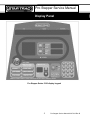
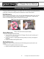
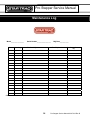
Pro Stepper
Service Manual
Table of Contents
Table of Contents.......................................................................................................................................................... 0
Display Panel ................................................................................................................................................................ 1
Preventive Maintenance ............................................................................................................................................... 2
Preventive Maintenance – Cont’d................................................................................................................................. 3
Settings - Maintenance Mode ...................................................................................................................................... 4
Settings - Maintenance Mode (cont.)........................................................................................................................... 5
Diagnostics - Display Codes........................................................................................................................................ 6
Diagnostics - LED Test ................................................................................................................................................ 7
Diagnostics - Keypad Test........................................................................................................................................... 8
Diagnostics - Heart Rate Test, Measurements............................................................................................................ 9
Trouble Shooting - How do I use the Stepper? ......................................................................................................... 10
Trouble Shooting - FAQ ............................................................................................................................................. 11
Trouble Shooting - Incorrect Model Setting ............................................................................................................... 12
Trouble Shooting - Noise ............................................................................................................................................ 13
Trouble Shooting – Noise- Clutch Pillow Blocks......................................................................................................... 15
Trouble Shooting – Noise - Springs............................................................................................................................ 16
Trouble Shooting – Noise - Pedals ............................................................................................................................. 17
Part Installation Procedure - Shrouds........................................................................................................................ 18
Parts Replacement – Shroud’s ................................................................................................................................... 18
Part Installation Procedure - Shrouds........................................................................................................................ 19
Part Adjsutment – Adjsuting Belt Tension .................................................................................................................. 20
Part Installation Procedure - Load Control board Wiring ........................................................................................... 21
Part Installation Procedure - Alternator Wiring .......................................................................................................... 22
Part Assemblies - Hardware Kit................................................................................................................................. 23
Part Assemblies - Clutch Assembly........................................................................................................................... 24
Part Assemblies - Display Assembly ......................................................................................................................... 25
Part Assemblies - Left Pedal Assembly..................................................................................................................... 26
Part Assemblies - Right Pedal Assembly .................................................................................................................. 27
Part Assemblies - Chain Link Assembly .................................................................................................................... 28
Part Assemblies - Electrical Components.................................................................................................................. 29
Part Assemblies - Frame Assembly Right ................................................................................................................. 30
Part Assemblies - Frame Assembly Left.................................................................................................................... 31
Part Assemblies - Frame Assembly Parts list............................................................................................................ 32
Part Assemblies - Frame Assembly........................................................................................................................... 33
See page 35 for parts list ........................................................................................................................................ 33
Part Assemblies - Frame Assembly........................................................................................................................... 34
See page 35 for parts list ........................................................................................................................................ 34
Maintenance Log ........................................................................................................................................................ 36
Pro Stepper Service Manual
Display Panel
Pro Stepper Series 5100 display keypad
1
Pro Stepper Service Manual 620-7619 Rev B
Pro Stepper Service Manual
Preventive Maintenance
To keep your Star Trac Pro Stepper in top condition, Star Trac strongly recommends performing
regular daily, weekly and monthly preventive maintenance routines outlined below.
Daily Maintenance
Remove excessive accumulations of dust, dirt and other substances by using a clean, soft cloth
and a non-abrasive liquid cleaner, such as Formula 409™ or FANTASTIK™. Wipe down the
exterior of the display panel, pedals, shrouds and heart rate grips.
Note: Do not spray directly on the display or heart rate grips.
Spray on the cloth first then wipe the display.
Weekly Maintenance
Perform the following services each week:
• Vacuum the floor under and around the Pro Stepper. Move the unit to another spot, if
necessary, to vacuum thoroughly.
• Inspect the screws (i.e. display panel mounting screws) for security, and retighten if
necessary.
• Inspect the display panel keypads for wear.
Monthly Maintenance
Perform all the steps in weekly maintenance plus the following services each month, or as
needed:
• Check that the pedals and shrouds are secure.
• Check for smooth and quiet operation of all moving parts.
2
Pro Stepper Service Manual 620-7619 Rev B
Pro Stepper Service Manual
Preventive Maintenance – Cont’d
Quarterly Maintenance
Perform all the steps in weekly and monthly maintenance plus the following services each month,
or as needed:
Remove the return springs form the chains:
• Raise and lower the pedal arms and inspect for smoothness. Binding or excessive
looseness might indicate a worn bushing.
• Rotate the clutch sprocket and inspect for smoothness. As you rotate the clutch towards
the pedals it will turn the drive belt but as you turn the clutch towards the drive belt it will
spin freely and will not turn the drive belt.
• Inspect the chain pulleys by spinning them.
a. If they spin freely they are ok
b. If they bind check for areas that bind and adjust or replace as needed.
• Inspect the chains and springs for wear.
a. Frozen links will require a chain replacement.
• Lubricate the chain with white lithium grease.
• Rotate the clutch sprockets 180 degrees from the original position and reassemble the
springs and chain back onto the sprockets.
3
Pro Stepper Service Manual 620-7619 Rev B
Pro Stepper Service Manual
Settings - Maintenance Mode
The Maintenance Mode allows you to query and modify the basic settings of the Star Trac Pro
Stepper.
Engaging Maintenance Mode
,
and
keys together.
Press and hold the
A beep will sound and the “MAINTENANCE MODE” will display momentarily in the information
window.
Release all keys. “SERIAL NO XXXXX” will display in the information window.
Modifying the Maintenance Mode
The following keys are used to modify Maintenance Settings:
Upper and Lower Data Information Window SCROLL keys: Display the next
previous settings.
and
Increase and Decrease Level Keys: Adjust the value of the displayed
setting up and down respectively, in increments of 1 unit.
OK Key: Updates (saves) the value of the display setting in the Flash memory, and exits
Maintenance Mode.
Maintenance Mode Settings
The items that you may display and change:
Default values set in ()
Pro Stepper serial number (0)
Manufactures date for the Pro Stepper (01/05)
Display software version (N/A)
Display software version (N/A)
LCB software version (N/A)
English = units of pounds, miles, feet inches; (English)
Metric = units of kilograms, kilometers, centimeters
Time Maximum time in minutes allowed for program, excluding warm-up and cooldown (20)
Weight Default (to user), typical weight in lb (UNITS=English) or kg (UNITS = Metric)
(350 lbs, 159 KG)
Serial Number
Date
Display Vers 1
Display Vers 2
LCB Vers
Units
4
Pro Stepper Service Manual 620-7619 Rev B
Pro Stepper Service Manual
Settings - Maintenance Mode (cont.)
Language Language is English, Dutch, French, German, Spanish, Swedish,
Italian or Katakana (English)
Model PB-UB = Pro Bike Upright, PB-RB = Pro Bike Recumbent, Pro CT =
Pro CrossTrainer, Elite CT = Elite CrossTrainer, Stepper = Pro
Stepper
LCB Type LCB hardware version Ver3
CSAFE Turns on/off CSAFE functionality (Off)
Auto Status Turns on/off the unsolicited status of the CSAFE feature (Off)
Wall Power Turns the wall power setting on/off (Off)
IRDA Turns on/off infrared port functionality (Off)
OPER Hours Total operating hours (0)
Quick Start Number of times the Quick Start program was run since last reset (0)
Manual Number of times the Manual program was run since last reset (0)
Fat Burner Number of times the Fat Burner program was run since the last reset
(0)
IHR Pro Number of times the Interval Heart Rate Control program was run
since the last reset (0)
CHR Pro Number of times the Constant Heart Rate Control program was run
since last reset (0)
Fit Test Number of times the Fitness Test program was run since last reset (0)
GLT Sculpt Number of times the Glute Sculptor program was run since last reset
(0)
Thigh TNR Number of times the Thigh Toner program was run since last reset (0)
Famous Step Number of times the Famous Step program was run since last reset
(0)
Comm Lost Number of times a Comm Lost condition has occurred. See Display
Codes
Key Down Number of times a Key Down condition has occurred. See Display
Codes
LED Test Access to integral LED test function
Keypad Test Access to integral keypad test function
Heart Rate Test Access to integral heart rate system test function
Measurements Access to integral measurements function
5
Pro Stepper Service Manual 620-7619 Rev B
Pro Stepper Service Manual
Diagnostics - Display Codes
Display Codes
Star Trac Pro Steppers perform a self-test at the beginning of every workout. If a problem is
detected, a message displays before or after the workout, depending on the nature of the
problem.
Key Down – One or more keys on the display panel are stuck in the “on” position for at least 10
seconds. This can occur if a user presses keys before the system is turned on.
Comm Lost – Communication between the Load Control Board (LCB) and the display are lost.
This can occur if the display cable is not connected securely at install.
6
Pro Stepper Service Manual 620-7619 Rev B
Pro Stepper Service Manual
Diagnostics - LED Test
LED Test
The LED Test can be used to verify that all LED (lights) are functioning on the display assembly.
To engage the LED Test
Enter the Maintenance Mode (see Settings – Maintenance Mode).
Press
until LED Test is displayed in the information window.
Press
to enter the LED Test. All lights on the display should be on.
Check for any burned out lights.
To exit the LED Test, press
.
If any of the LED’s do not illuminate, they may not be functioning and the display electronics
should be replaced.
7
Pro Stepper Service Manual 620-7619 Rev B
Pro Stepper Service Manual
Diagnostics - Keypad Test
Keypad Test
The Keypad Test can be used to verify that all keys are functioning on the display assembly.
To engage the Keypad Test
Enter the Maintenance Mode (see Settings – Maintenance Mode).
Press
until Keypad Test is displayed in the information window.
Press
to enter the Keypad Test.
Press each key on the display. Each time you press a key, the information window will display
which key has been pressed.
To exit the keypad test, press
.
If any of the keys do not respond, they may not be functioning and the display keypad must be
replaced.
8
Pro Stepper Service Manual 620-7619 Rev B
Pro Stepper Service Manual
Diagnostics - Heart Rate Test, Measurements
Heart Rate Test
Heart Rate can be checked using the Heart Rate Test.
To verify heart rate operation:
Enter the Maintenance Mode (see Settings – Maintenance Mode).
Press
until Heart Rate Test is displayed in the information window.
Press
to enter Heart Rate Test.
The display will read TELEMETRY.
If checking contact heart rate it will read “CONTACT” and the heart rate number.
If checking Polar, the display will read “TELEMETRY” and the heart rate number.
.
5. To exit the heart rate test, press
Measurements Mode
Measurements can be done to verify the voltage of the battery.
To verify the battery voltage:
Enter the Maintenance Mode (see Settings – Maintenance Mode).
Press
until Measurements is displayed in the information window.
Press
to enter Measurements.
The display will read “BATT VLT = “and the voltage of the battery.
To exit the measurements, press
.
9
Pro Stepper Service Manual 620-7619 Rev B
Pro Stepper Service Manual
Trouble Shooting - How do I use the Stepper?
Q. Why does the stepper not have any resistance when I increase the level?
A. When pressing the upS or down T key you are actually changing the workout level of the
user.
Press the increase (UP) S level key the pedals will fall faster and there is less resistance so you
have to work harder to keep up with it.
Press the down level (DOWN) Tit makes the pedals move slower so it is easier to keep up with it.
Do not let the pedals touch the floor. Step fast enough to keep the pedals in their middle
range, with step heights from 2 to 16 inches. If the pedals sink to the floor, step faster or decrease
your work level by pressing the level down keyT.
10
Pro Stepper Service Manual 620-7619 Rev B
Pro Stepper Service Manual
Trouble Shooting - FAQ
Symptom
Possible Problem
Solution
Page #
Squeaking noise
Loose bearing
Check all bearings
14
Clicking Noise
Possible spacer missing
Examine clutch
assembly
23
Popping noise
Frozen link on chain
Examine chain links
27
Pedals Slip
Possible clutch failure
Loose Pedals
Bushing wear
No Power
Low battery
No resistance
(Pedals fall) at level1
to 5
Too much resistance
(Pedals won’t move) at
level 10 to 15
Possible low battery or
RPM sensor out of
alignment
Possible model error or
LCB failure
Perform clutch and belt
test
Inspect bushings on
pedal arms and pedals
Check battery and
connections
Check battery voltage
and rpm senor alignment
Check model in
Maintenance mode.
Swap LCB
Check RPM sensor LED
on LCB (Load control
board)
Change Model to Pro
Stepper
Change Model to Pro
Stepper
19
16
29
28
12
Turns on but does not
give speed
RPM sensor
Start Pedaling
Wrong Model Selected
Start Striding
Wrong Model Selected
I forgot where the
wires go on the
alternator
Wires may be in the wrong
position
Refer to the wiring photo
21
I’m replacing the LCB
but am not sure where
the connectors plug in.
The connectors are all
different shapes so it is not
possible to plug them in the
wrong place
Refer to the LCB wiring
diagram
20
11
18
12
12
Pro Stepper Service Manual 620-7619 Rev B
Pro Stepper Service Manual
Trouble Shooting - Incorrect Model Setting
The display electronics on the Pro Stepper can be configured to operate with many different
models of Star Trac products. For them to operate properly, the correct model must be set in the
Maintenance mode.
If the correct model is not set, the following may happen:
When the unit is powered up, the display will read “Pro Bike” (or Pro CrossTrainer or Elite
CrossTrainer) in the level profile window.
The display will read “Start Pedaling” or “Start Striding” instead of “Start Stepping”.
Also, some programs will not work when the keys are pressed. i.e. When pressing the Hr Training
Program Key, the Total Body program or Warm Up program will start.
If you experience any of these symptoms, engage the Maintenance mode to correct the Model
setting.
Engaging Maintenance Mode
Press and hold the
,
and
keys together.
A beep will sound and the “MAINTENANCE MODE” will display momentarily in the information
window.
Release all keys. “SERIAL NO XXXXX” will display in the information window.
Press the
until the display reads “Model”.
until the correct setting shows.
Press the
Stepper = Pro Stepper
Press
to save the setting and exit the maintenance mode.
Test for functionality.
12
Pro Stepper Service Manual 620-7619 Rev B
Pro Stepper Service Manual
Trouble Shooting - Noise
Noise is one of the hardest things to diagnose because it may only make the noise under certain
conditions. To find the part that is making the noise will require some patience and trial and error.
It may also require the help of another person to slowly and safely move the part while another
person listens.
NOTE: Always use safe work practices and do not allow clothing, hair or fingers to get caught in
moving parts.
Try these methods when trying to locate the noise:
• Move the product to a quiet location to help in diagnosing the noise when possible.
• Loosen or tighten screws to make the noise louder or eliminate the noise. Often a noise
•
•
•
•
•
will change its pitch when you do this and that may point you towards the correct part.
Gently and carefully when possible spray a little lube on the bearing or shaft to see if the
noise will get quieter. This is very successful when a shaft is spinning within a bearing and
making a squealing noise.
Remove part of the moving assembly to help isolate the noise.
Try swapping parts, such as with the pedal springs, one spring may make a noise and not
the other. Swap the springs to determine if the spring is at fault or the pulley, etc.
Check for worn or damaged parts such as a worn spot on a plastic pulley.
Look for metal shavings which might indicate a worn bearing or a set screw that is not tight.
The following pages discuss some areas that have moving parts and could be the source of
noise.
Proper cleaning and lubrication as suggested in maintenance can prevent noises.
13
Pro Stepper Service Manual 620-7619 Rev B
Pro Stepper Service Manual
Return Spring Pulley Replacement– Pro Stepper
Parts replacement
1. Insert the shaft a quarter into the frame.
2. Slide one of the two pulleys onto the shaft.
3. Slide the shaft halfway into the frame.
4. Slide the other pulley onto the shaft.
5. Slide the shaft into the other side of the frame.
6. Make sure there is a gap between the pulleys and the frame.
7. Slide the collar on the shaft ends outside the frame as shown by the arrows.
8. Align the shaft so it is even on both sides.
9. Tighten the set screws on the collars using the 1/8” Allen wrench.
Adjustments and testing
10. Align the pulleys centered with the pedal arm.
11. Check to make sure the pulleys rotate freely and do not make noise ad you step on
the pedals and use the stepper.
12. Examine the pulleys again and make sure they are not touching the frame.
14
Pro Stepper Service Manual 620-7619 Rev B
Pro Stepper Service Manual
Trouble Shooting – Noise- Clutch Pillow Blocks
The noise that you might hear as a result of the pillow block bearings being loose is a
slight click or ticking sound.
•
•
•
Use two 9/16 wrenches (or socket
and wrench) to verify that all 4 bolts
and nuts on the upper and lower
pillow block assemblies are tight.
Loosen the nuts and then ride it a
little to let it settle, then tighten the
nuts to determine if the noise is from
the alignment of the shaft to the
bearing.
Loosen the set screws and rotate the
shaft so the set screw is in the detent
in the shaft. Tighten the set screw in
the detent first then the other set
screw and repeat the procedure on
the other side.
.
15
Pro Stepper Service Manual 620-7619 Rev B
Pro Stepper Service Manual
Trouble Shooting – Noise - Springs
Noise from the springs may make a pinging or a rubbing sound. Check the spring to make sure it
is not twisted and the pulley is turning as the spring rolls over it.
16
Pro Stepper Service Manual 620-7619 Rev B
Pro Stepper Service Manual
Trouble Shooting – Noise - Pedals
• Check all hardware under the pedals for looseness.
• Check clips and springs to make sure they are aligned properly so they do not come off.
17
Pro Stepper Service Manual 620-7619 Rev B
Pro Stepper Service Manual
PartParts
Installation
Procedure
- Shrouds
Replacement
– Shroud’s
Parts Needed:
Shroud Left (711-3165-01)
Shroud Right (711-3165-02)
Tools Needed:
Phillips Head Screwdriver
Procedure:
Shroud removal
1. Remove the 4 screws on the inside front of the shroud and
lift the shroud off the frame.
2. Remove the Shroud by unscrewing the 6 screws on each
side of the shrouds.
3. Be careful not to pull on any of the cables as you remove the
shroud.
Shroud replacement
1. Place the side shrouds on first. Install the 6 screws per side.
2. Install the front shroud and 4 small screws.
18
Pro Stepper Service Manual 620-7619 Rev B
Pro Stepper Service Manual
Part Installation Procedure - Shrouds
Open the left side for
testing the alternator and
the cables.
The RPM sensor and alternator
adjustments are accessible from the right
side.
The gap on the RPM sensor should be
approx. 1 credit card.
19
Pro Stepper Service Manual 620-7619 Rev B
Pro Stepper Service Manual
Part Adjsutment – Adjsuting Belt Tension
To adjust the tension of the main drive belt perform the following check.
• If the drive belt is slipping on the
adjustable bracket assembly or the main
pulley in-between the clutch sprockets, the
belt will have to be tightened.
• Using a 9/16” inch open end wrench,
loosen the large nuts holding the
adjustable bracket on the frame of the
stepper.
• Using a 7/16” open end wrench or socket
wrench, turn the bolt in the front of the
frame.
• To tighten the belt, turn the bolt clockwise
this will pull the adjustable bracket
forward. This will tighten the belt.
• To loosen the belt, turn the bolt counter
clockwise. This will push the adjustable
bracket closer to the pedals. This will
loosen the belt.
20
Pro Stepper Service Manual 620-7619 Rev B
Pro Stepper Service Manual
Part Installation Procedure - Load Control board Wiring
LCB Wiring
• The LCB is protected from sweat and moisture by a clear plastic cover, remove
•
•
•
•
this cover while accessing the LCB.
All the connectors are keyed and will only fit properly in one direction.
Make sure the connector is fully seated and locked.
Run wires away from moving parts and tie wrap as needed.
Not the RPM led, this will be lit when the rpm sensor is detecting the rotation of
the alt flywheel.
21
Pro Stepper Service Manual 620-7619 Rev B
Pro Stepper Service Manual
Part Installation Procedure - Alternator Wiring
Alternator Wiring
The alternator is wired as shown in the above photo. Make sure
contacts are clean and secure.
22
Pro Stepper Service Manual 620-7619 Rev B
Pro Stepper Service Manual
Part Assemblies - Hardware Kit
23
Pro Stepper Service Manual 620-7619 Rev B
Pro Stepper Service Manual
Part Assemblies - Clutch Assembly
Kit Part Number 800-3114
Drive Shaft Assembly
24
Pro Stepper Service Manual 620-7619 Rev B
Pro Stepper Service Manual
Part Assemblies - Display Assembly
Drawing # 711-3151
25
Pro Stepper Service Manual 620-7619 Rev B
Pro Stepper Service Manual
Part Assemblies - Left Pedal Assembly
26
Pro Stepper Service Manual 620-7619 Rev B
Pro Stepper Service Manual
Part Assemblies - Right Pedal Assembly
27
Pro Stepper Service Manual 620-7619 Rev B
Pro Stepper Service Manual
Part Assemblies - Chain Link Assembly
28
Pro Stepper Service Manual 620-7619 Rev B
Pro Stepper Service Manual
Part Assemblies - Electrical Components
29
Pro Stepper Service Manual 620-7619 Rev B
Pro Stepper Service Manual
Part Assemblies - Frame Assembly Right
See page 32 for parts list
30
Pro Stepper Service Manual 620-7619 Rev B
Pro Stepper Service Manual
Part Assemblies - Frame Assembly Left
See page 32 for parts list
31
Pro Stepper Service Manual 620-7619 Rev B
Pro Stepper Service Manual
Part Assemblies - Frame Assembly Parts list
32
Pro Stepper Service Manual 620-7619 Rev B
Pro Stepper Service Manual
Part Assemblies - Frame Assembly
See page 35 for parts list
33
Pro Stepper Service Manual 620-7619 Rev B
Pro Stepper Service Manual
Part Assemblies - Frame Assembly
See page 35 for parts list
34
Pro Stepper Service Manual 620-7619 Rev B
Pro Stepper Service Manual
35
Pro Stepper Service Manual 620-7619 Rev B
Pro Stepper Service Manual
Maintenance Log
Model________________
Date
Cleaning
Serial Number_________________
Problem/Adjustment
Mfg Date___________
Part Replaced
Service performed
by
Comments:
36
Pro Stepper Service Manual 620-7619 Rev B
800-503-1221
http://support.startrac.com/