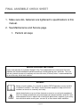
1
IP-L8505
OWNERS MANUAL and
INSTALLATION INSTRUCTIONS
Copyright 2010. Star Trac by CORE INDUSTRIES. All rights reserved, including those to reproduce this
book or parts thereof in any form without first obtaining written permission from Star Trac.
Every effort has been made to keep this information current; however, periodically, changes are made to the
information herein, and these changes will be incorporated into new editions of this publication. All product
names and logos are trademarks of their respective owners. Printed in the USA.
Page 2
TABLE OF CONTENTS
•
SAFETY INSTRUCTIONS / WARNINGS
4
•
WARNING LABLES WITH PART NUMBERS
6
•
EXERCISE GUIDELINES
7
•
MAINTENANCE AND SERVICE
8
•
WARRANTY COVERAGE
9
•
INSTALLATION INSTRUCTIONS
11
•
21
HARDWARE
Page 3
Safety Instructions
Max Rack Safety Information and General Exercise Guidelines
Safety Information
Read the Max Rack Owner's Manual carefully before assembling, servicing or using the Max Rack.
! WARNING: Serious injury or death could occur if these
safety precautions are not observed:
1.
Do not use the Max Rack in any way other than designed or intended by the
manufacturer. It is imperative that the Max Rack as well as any other STAR TRAC
STRENGTH equipment is used properly to avoid injury.
2.
Keep hands, feet, head, limbs, fingers and hair clear at all times from moving parts to
avoid injury. Use appropriate positioning, speed and controlled movements.
3.
DO NOT use any equipment that is damaged and or has worn or broken parts. Use only
replacement parts supplied by STAR TRAC.
4.
DO NOT wear loose or dangling clothing while using the STAR TRAC equipment. Keep
away from all moving parts.
5.
Obtain a medical exam prior to beginning an exercise program.
6.
If at any time during exercise you feel faint, dizzy or experience pain, stop and consult
your physician.
7.
Children must not be allowed near these machines. Teenagers must be supervised.
8.
DO NOT attempt to fix a broken or jammed machine. Contact appropriate staff of Star
Trac Service.
9.
Use the machine only for the intended use. Obtain instruction and DO NOT modify the
machines.
10.
Load plates evenly and carefully to avoid tipping equipment and possible crushing
injuries. DO NOT exceed maximum load of 500 lbs (227.3 kgs) DO NOT exceed 230 lbs
(104.5 kgs) per side of loaded weight.
11.
ALWAYS USE safety stops as directed DO NOT use if guards are missing or damaged.
12.
ALWAYS position safety stops as outlined on the user placard descriptions for each
movement.
13.
USE A SPOTTER for all activities.
14.
MAINTAIN LABELS AND NAMEPLATES: Do not remove labels for any reason. They
contain important information. If unreadable or missing, contact STAR TRAC for a
replacement.
Page 4
15.
16.
17.
18.
19.
20.
21.
22.
23.
24.
25.
26.
27.
SECURING EQUIPMENT: All STAR TRAC equipment MUST be secured to the floor to
stabilize and eliminate rocking or tipping over. This must be performed by a licensed
contractor. DO NOT use the Weight equipment if it is not set up and located on a solid
level surface.
Make sure that each machine is set up and operated on a solid level surface. DO NOT
install equipment on an uneven surface.
MAINTAIN ALL EQUIPMENT: Preventative maintenance is the key to smooth operating
equipment as well as keeping your liability to a minimum. Inspect the STAR TRAC
equipment prior to use. DO NOT use if damaged or inoperable.
Ensure that any person (s) making adjustments or performing maintenance or repair of
any kind is qualified to do so.
Routinely inspect all fasteners that join attachments and framework tighten as needed to
maintain the integrity of the unit.
It is the purchaser's sole responsibility to properly instruct its end users and supervising
personnel as to the proper operating procedures of all STAR TRAC equipment. It is
recommended that the end users physical condition be evaluated prior to beginning any
exercise program.
Perform regular maintenance checks on the STAR TRAC equipment. Also, pay close
attention to all areas most susceptible to wear.
Keep a repair log of all maintenance activities.
Immediately replace worn or damaged components. If unable to immediately replace
worn or damaged components then remove the STAR TRAC piece of equipment from
service until the repair is made.
Make sure that all users are properly trained on how to use the STAR TRAC equipment.
Make sure there is enough room for safe access and operation of the STAR TRAC
equipment.
Use only STAR TRAC supplied components to maintain/repair the STAR TRAC
equipment.
UNDERSTANDING EACH AND EVERY WARNING TO THE FULLEST IS IMPORTANT.
IF ANY OF THESE WARNINGS ARE UNCLEAR, ASK FOR CLARIFICATION FROM
STAR TRAC PERSONNEL.
NOTE: It is the sole responsibility of the user/owner or facility
operator to ensure that regular maintenance is performed.
Page 5
Page 6
Exercise Guidelines
•
Like most exercise, strength training involves an element of risk. Utilize this information to
assist you and/or your members in making the experience on STAR TRAC both productive and
safe.
•
Prior to engaging in any strength-training program, individuals with known health conditions
and/or individuals whom are unfamiliar with the risk (s) involved with weight training, should first
consult with a physician.
•
All training sessions should be supervised by trained personnel.
•
Be certain that the warning stickers affixed on STAR TRAC, remain on the product and
unaltered. Also, be certain that all the stickers (safety, instructional and/or other) are read and
understood by each user.
•
All users should be instructed on the proper use of STAR TRAC as well as those actions that
should be avoided.
•
The STAR TRAC Max Rack has safety catches specifically designed to enhance the use of the
product and protect the user – ALWAYS use the safety catches as outlined on the user
placards.
In an attempt to minimize user and/or bystander injury:
•
Do not lean against framework, plate holders or any component whether it is dynamic or static.
•
Stay clear of any components while in a dynamic state of motion. Keep hands and feet away
from all moving parts. The convergence of these components can cause serious injury.
•
Exercising on free weight and selectorized products should be performed with the assistance of
a spotter.
•
Always insure proper positioning of the safety stops during each exercise set.
Page 7
MAINTENANCE AND SERVICE
The Max Rack requires very little upkeep to keep your Max Rack performing at its best, the
following guidelines are suggested.
GENERAL CLEANING
Wipe the Max Rack with a light all-purpose cleaner, such as diluted Simple Green at a
30:1 solution.
Dry the Max Rack with a soft cloth to prevent rust.
To prevent rust build up it is advised to wipe the Max Rack with a soft cloth and some
LPS-1 rust preventative.
Do not clean the guide rods or bearings as this will cause failure of the bearings.
LUBRICATION OF GUIDE RODES
Place light oil (i.e. Three-In-One) onto a clean rag and wipe it along the vertical and
horizontal steel rods monthly.
The bearings inside the barbell housings are sealed and require no maintenance.
Do not use grease or heavy lubricating oil.
Page 8
Warranty Coverage
Star Trac commercial exercise equipment (.Product.) is warranted to be free of all defects in material and
workmanship.
Star Trac warrants all structural frameworks for a period of 10 years. This limited warranty on structural frame
does not include coatings. The following moving parts are warranted for 5 years; rotary bearings and
structural moving parts. All unlisted parts handles and accessories are warranted for 1 year. Upholstery is
warranted for 6 months.
Who is covered
The original purchaser or any person receiving the Product as a gift from the original purchaser.
Who pays for transportation and insurance for service
If the Product or any covered part must be returned to a service facility for repairs, We, Star Trac, will pay all
transportation and insurance charges for the first year. You are responsible for transportation and insurance
charges during the second and third years (if applicable).
What Star Trac will do to correct covered defects
We will ship to you any new or rebuilt replacement part or component, or, at our option, replace the Product.
Such replacement parts are warranted for the remaining portion of the original warranty period.
What is not covered
Any failures or damage caused by unauthorized service, misuse, accident, negligence, improper assembly or
installation, debris resulting from any construction activities in the Product’s environment, rust or corrosion as
a result of the Product’s location, alterations or modifications without our written authorization or by failure on
your part to use, operate and maintain the Product as set out in your Operation Manual (.Manual.).
All terms of this warranty are void if this product is moved beyond the continental borders of the United States
of America (excluding Alaska, Hawaii and Canada) and are then subject to the terms provided by that
country’s local authorized Star Trac representative.
Operation Manual
It is very important that you read and review this manual before operating the Product. Remember to perform
the periodic maintenance requirements specified in the Manual to assure proper operation and your continued
satisfaction.
How to get parts and service
Contact Star Trac Customer Support Services Monday through Friday from 8:00 a.m. to 6:00 p.m. Pacific
Standard Time, and tell them your name, address and the serial number of your Product. They will tell you
how to get a replacement part, or, if necessary, arrange for service where your Product is located or advise
you on how and where to ship the Product for service.
Visit us on line at http://www.startrac.com/us-en/Support
Customer Services Hot Line: 1 800 503 1221
Fax: 1 714 669 0739
[email protected]
International Customer Services: +1 714 508 3796
Fax: +1 714 669 0739
[email protected] or [email protected]
Page 9
Exclusive warranties
THIS LIMITED WARRANTY IS IN LIEU OF ALL OTHER WARRANTIES OF ANY KIND EITHER
EXPRESSED OR IMPLIED, INCLUDING BUT NOT LIMITED TO THE IMPLIED WARRANTIES OF
MERCHANTABILITY AND FITNESS FOR A PARTICULAR PURPOSE, AND ALL OTHER OBLIGATIONS
OR LIABILITIES ON OUR PART.
We neither assume nor authorize any person to assure for us any other obligation or liability concerning the
sale of this Product. Under no circumstances shall we be liable under this warranty, or otherwise, of any
damage to any person or property, including any lost profits or lost savings, for any special, indirect,
secondary, incidental or consequential damages of any nature arising out of the use of or inability to use this
Product. Some states do not allow the exclusion or limitation of implied warranties or of liability for incidental
or consequential damages, so the above limitations or exclusions may not apply to you.
Changes in warranty that are not authorized
No one is authorized to change, modify or extend the terms of this limited warranty.
Effects of state laws
This warranty gives you specific legal rights and you may have other rights, which vary, from state to state.
Our commitment to you
Our Products are designed and manufactured to the highest standards.
We want you completely satisfied with our Products and will do everything possible under the terms of this
warranty to meet and exceed your expectations.
Page 10
INSTALLATION INSTRUCTIONS
REQUIRED TOOLS:
• 13mm Box / Open-End Wrenches
•• • • • • •• • • • • • • • • • • •
2
• 17mm Box / Open-End Wrenches • • • • • • • • • • •• • • • • • • • •
GENERAL NOTES:
•
Unless otherwise noted Loctite 242/243 or equivalent thread locker must be used on all threaded fasteners. (Do not use
thread locker when a Nyloc nut is used.)
•
All Star Trac Strength equipment MUST be secured to the floor using either 10mm or 3/8in. (grade 5 minimum) bolts.
To accommodate this there are four mounting points inside the weight stack and one in either of the small feet.
•
This Installation Instructions Manual must be used in conjunction with the equipment’s Owner’s Manual. The Owner’s
manual describes equipment setup and instructs members on how to use it correctly and safely.
•
The Max Rack requires at least two people to perform the installation.
THREAD LOCKER APPLICATION: Clean all threads and holes, apply no more than 3-4 drops per bolt.
Thru Holes
Blind Holes
Metric Steel Bolts Torque Specifications
Bolt Size
Thread Pitch
Torque, N-m (lbs-ft)
6mm
1.25
10 to13.5 (8 to10)
8mm
1.25
25.5 to 28.5 (19 to 21)
10mm
1.75
55.5 to 58 (41 to 43)
12mm
1.25
61 to 65 (45 to 48)
• Torque all hardware to values as specified above, unless noted otherwise.
• See Page 11 of this manual for fastener sizing information; for reference only.
• Note: All torque values are in N-m unless otherwise stated.
Should any component not be present or if you have any operational questions, please refer to your owner’s manual or on the
web @ www.startrac.com . Specifically refer to your Inspiration serial number and model number labeled on your equipment.
PACKAGING REMOVAL:
Carefully remove all packaging materials that wrap the equipment. DO NOT USE A KNIFE OR BOX
CUTTER AS YOU MAY DAMAGE THE EQUIPMENT. At this time remove any sub-components from
the pallet and set aside for later assembly.
Page 11
2
UNPACK THE MAX RACK and ASSEMBLE UPPER WELDMENTS:
NOTE: TAKE CARE WHILE OPENING THE BOXES. KEEP TRACK OF ALL ITEMS YOU REMOVE FROM
THE BOXES. TAKE CARE NOT TO LAY ITEMS ON SURFACES THAT MAY SCRATCH THE
PRODUCT.
1.
Take the front and back upper weldments and place them on a soft surface. (A moving blanket will
help reduce damage from hard surfaces)
2.
Take (2) of the cross weldment and lay them between the upper weldments.
3.
Take (4) bracket and lay (2) at each end as shown below.
4.
You will need (8) m10 x 140mm Hex Head bolts (PN:731-2398), (8) m10 Nyloc nuts (PN:731-2420),
and (16) m10 washers (PN:731-2419). NOTE: Make sure you use the right length of bolt.
5.
Using (2) 17MM box wrenches assemble the components as seen below. Snug the fasteners at this
time.
Page 12
ASSEMBLE UPRIGHTS:
1.
Take the (4) uprights and slide the onto the correct post sleeve. See images below. Note: the (2)
fixed feet go onto the sleeved weldment with the handle grips. The adjustable feet go in the back. All
mounting holes are to the outside of the user area.
2.
Take (20) m10 washers (PN:731-2419) and (20) m10 x 25 Hex Head bolts (PN:731-2333). NOTE:
Remember to use thread locker.
3.
Using a 17mm box wrench install and tighten all (20) fasteners as shown below.
Fixed
Fixed
Adjustable
Adjustable
Page 13
UPRIGHT MAIN ASSEMBLY:
NOTE: due to the weight of the assembly, you should always have at least 2 people when moving these
assemblies.
1.
Lay assembly on its side. Support legs as you rotate assembly. Note: take special care not to drop
the assembly.
2.
Lift top of assembly to upright the Main frame.
MOVE MAIN ASSEMBLY:
1.
Move assembly to the position where it will be used, remember to leave room behind for the rest of
the assembly. NOTE: Make sure you leave enough space to allow a safe and clear workout area.
2.
Install (4) boots (PN:731-0021) under the feet.
Page 14
INSTALL WEIGHT HOLDERS:
1.
Take the (2) weight holder weldments (PN:731-2355-XX) from the packaging.
2.
Using (2) mounting plate (PN:731-23), (4) m10 x 140 Hex Head Bolts (PN:731-2398), (8) m10
Washers (PN:731-2419), and (4) m10 Nyloc Nuts (PN:731-2420), install the weldment to the back of
the Main Assembly. Before tightening Fasteners place (2) boots (PN:731-0021) under the feet of the
weldments. Use (2) 17mm box wrenches to lightly tighten these fasteners at this time. NOTE: Make
sure you use the right length of bolt.
INSTALL LOWER BRACES:
1.
Take the (2) cross brace weldments (PN:731-2317-XX) from the packaging.
2.
Using (2) brackets (PN:731-2315-XX), (8) m10 x 140 Hex Head Bolts (PN:731-2398), (16) m10
Washers (PN:731-2419), and (8) m10 Nyloc Nuts (PN:731-2420) install the weldments between the
legs of the Main Assembly. Adjust all six feet to firm to the ground. Use (2) 17mm box wrenches
tighten all fasteners at this time even upper cross members. NOTE: Make sure you use the right
length of bolt.
Page 15
INSTALL BACK BRACE:
1.
Take the Back Cross Brace (PN:731-2379-XX) from the packaging.
2.
Using (2) mounting plate (PN:731-2379-XX), (8) m10 x 80 Hex Head Bolts (PN:731-2400), (16) m10
Washers (PN:731-2419), and (8) m10 Nyloc Nuts (PN:731-2420), install the weldment between the
two weight holders. Use (2) 17mm box wrenches to tighten these fasteners at this time.
INSTALL BAR HOLDERS:
1.
Take the (4) Bar Holders (PN:731-2331) from the packaging.
2.
Using (12) m10 x 135 Hex Head Bolts (PN:731-2334), (12) m10 Washers (PN:731-2419), (12) M10
Large Washers (PN:731-2346), and (12) m10 Nyloc Nuts (PN:731-2420), install the weldments to the
upright legs. Take note of the Workout Placards, make use they are facing the inside of the unit. Look
at the bottom of each placard for the number and use the image below for placement on the unit. Use
(2) 17mm box wrenches to tighten these fasteners at this time. NOTE: Make sure you use the
right length of bolt.
Page 16
INSTALL UPPER GUIDE RODS:
1.
Take (2) Ø25mm Guide Rods (PN:731-2392) and the Upper Bearing Weldment (PN:731-2349-XX)
from the packaging.
2.
You will use (4) Spacer rings (PN:731-2395), (4) m10 x 25 Hex Head Bolts (PN:731-2333), and (4)
m10 Large Washers (PN:731-2396), to install the Guide Rods into the upper mounts. Use a 17mm
box wrench to install one bolt washer and space into one end of each rod. Slide the rods through the
front mounts taking care not to scratch rods. With the rods through the first mounts now slide the
Bearing Weldment (PN:731-2349-XX) over the rods (the larger hole at the ends of the weldment
should be facing down), NOTE: DO NOT force the bearing onto the rods this may damage the
bearings. Once the Bearing Weldment is on both rods, slide the rods through the back mounts.
3.
Take 2 spacers, washers, and bolts, install them on the other end of the Guide rods. Using (2) 17mm
box wrenches tighten the fasteners.
INSTALL BEARING MOUNTS TO BAR:
1.
Take the (2) Bearing Mounts (PN:731-2385-XX) from the packaging.
2.
Using (4) m10 x 35 Hex Head Bolts (PN:731-2399), (8) m10 Washers (PN:731-2419), and (4) m10
Nyloc Nuts (PN:731-2420), install the weldments to the bar. NOTE: the weldments install to the
outside of the bar flange
Page 17
INSTALL SAFETY STOPS:
1.
Take the (2) Safety Stops (PN:731-2337) from the packaging.
2.
Install the Safety Stops onto the machine at this time, make sure they are both at the same level.
3.
Take the Bar with the Bearing guides and place it on the safety stop as in the image.
INSTALL BEARING MOUNTS TO BAR:
1.
Take the (2) Ø30mm Guide rods with threaded hole in one end (PN:731-2393) from the packaging.
2.
Using (2) m10 x 25 Hex Head Bolts (PN:731-2333), and (2) m10 Large Washers (PN:731-2396),
install the rods through the bar bearing guides with the threaded holes up and the bearing tube to the
back of the machine, then push the rod up into the upper bearing weldment. NOTE: DO NOT force
the rod into the bearing this may damage the bearings.
3.
Use a 17mm box wrench to tighten the bolts.
Page 18
INSTALL THE LOWER GUIDE RODS:
1.
Take the (2) Ø30mm Guide Rods with threaded holes at both ends (PN:731-2391), (2) Round Rubber
Bumpers (PN:731-2394), and (2) “T” shaped Bearing Tubes (PN:731-2390) from the packaging.
2.
You will use (4) Spacer rings (PN:731-2397), (4) m10 x 25 Hex Head Bolts (PN:731-2333), and (4)
m10 Large Washers (PN:731-2396), to install the Guide Rods into the lower mounts. Use a 17mm
box wrench to install one bolt, washer and spacer onto one end of each rod. Slide the rods through
the front mounts taking care not to scratch rods.
3.
Take one of the “T” shaped Bearing Weldments, and one of the Rubber Bumpers and slide them over
the end of one of the vertical rods (See Below). Now slide the horizontal Guide Rod through the
bearings of the “T” shaped Bearing Tube. NOTE: DO NOT force the bearing onto the rods this may
damage the bearings. Once the Bearing Weldment is on the rods, slide the rod through the back
mount.
4.
Take 2 spacers, washers, and bolts, install them on the other end of the Guide rods. Using (2) 16mm
box wrenches tighten the fasteners.
Page 19
INSTALL WEIGHT HORNS:
1.
Take the (4) Long Weight Horn weldments (PN:731-1454), (4) Short Weight Horn weldments
(PN:731-2297), (12) Weight Horn Covers (PN:731-1376), (12) Base Covers (PN:731-1373), and (12)
End Caps (PN:731-1374) from the packaging.
2.
Using (16) M8 x 75mm Hex Head Bolts (PN:731-2356), (32) M8 Washers (PN:731-2421), and (16)
M8 Nyloc Nuts (PN:731-2422) install the weight horns. See image below for placement and order.
Use (2) 13mm box wrenches to tighten fasteners.
3.
Once all the weight horns are installed, slide on each side the Base Covers then the Horn Sleeve,
and last the Horn Cap.
4.
Once all the caps are installed take the number sticker and apply them to the appropriate cap (see
below). NOTE: the sticker page has both LBS and KG, decide which units you want and then apply
the appropriate stickers.
2.5lbs
or
1.25kg
10lbs
or
5kg
5lbs or
2.5kg
25lbs
or
10kg
35lbs
or
15kg
45lbs
or
20kg
Page 20
Page 21
FINAL ASSEMBLE CHECK SHEET
1. Make sure ALL fasteners are tightened to specifications is this
manual.
2. See Maintenance and Service page.
1. Perform all steps
MACHINE CLEARANCE AND SPACING
For the safe operation of Inspiration Strength™ Star Trac recommends that a clearance of 24 inches
(60.96cm) be maintained between and behind machines including moving arms and levers. To insure
safe entry and exit to each unit a walkway of at least 36 inches (91.44cm) inches is recommended front
of, or on the entry side of each machine.
WARNING!
Before using this product, it is essential to read the ENTIRE operations manual and ALL
installation Instructions. The Owner’s manual describes equipment setup and instructs
members on how to use it correctly and safely.
Health related injuries may result from incorrect or excessive use of exercise equipment.
Star Trac strongly recommends you to encourage you and your members to discuss their
health program or fitness regimen with a health care professional, especially if you or they
have not exercised for several years, are over 35, or have known health conditions.
Page 22
Page 23
STAR TRAC
14410 Myford Road
Irvine, California 92606
Telephone: (800) 228-6635, (714) 669-1660
Fax: (714) 508-3303
www.startrac.com
Part No. 620-8048, Rev A., OCT 2010