1
Users Guide
Ve rsion 2.0
CONTENTS
Danger
During normal operation of this device, hazardous voltages are present which can
cause severe injury or death. These voltages are present on the terminal strips of the
device and throughout the connected potential transformer (PT), current transformer
(CT), status input, relay, and control power circuits. Installation and servicing should
be performed only by qualified, properly trained personnel. See the 7700 ION
Installation & Basic Setup Instructions for further details.
Warning
For further information or technical assistance, please
contact your local Power Measurement representative,
or Customer Service at one of the following locations:
This equipment generates, uses, and can radiate radio frequency energy and if not
installed and used in accordance with the instructions manual, may cause interference
to radio communications. It has been tested and found to comply with the limits for a
Class A computing device pursuant to Part 15 of FCC Rules, which are designed to
provide reasonable protection against such interference when operated in a commercial environment. Operation of this equipment in a residential area may cause
interference in which case the operator will be required to take whatever measures
may be required to correct the interference.
Limitation of Liability
Toll Free
1-877-METER-IT
(1-877-638-3748)
World-Wide Web www.pml.com
Worldwide Headquarters
POWER MEASUREMENT LT D.
2195 Keating Cross Road,
Saanichton, BC,
Canada V8M 2A5
Tel: 1-250-652-7100
Fax: 1-250-652-0411
Europe & Middle East
PO W E R M E A S U R E M E N T E U R O P E
Zaventem Business Park,
Ikaroslaan 5, B-1930 Zaventem
(Brussels), Belgium
Tel: 32-2-720-19-19
Fax: 32-2-720-95-86
Asia & Pacific
POWER MEASUREMENT AUSTRALIA
7/16 Ledgar Road,
Balcatta, Perth
Western Australia 6021
Tel: 61-9-345-3866
Fax: 61-9-345-3899
Revision Date: September 21, 1998
© 1998 Power Measurement Ltd.
All rights reserved
Printed in Canada
70000-0114
Power Measurement Limited reserves the right to make changes in the
devices or the device specifications identified in this Retrofit Installation Instructions
without notice. Power Measurement Limited advises customers to obtain the latest
version of device specifications before placing orders to verify that the information
being relied upon by the customer is current.
In the absence of written agreement to the contrary Power Measurement Limited
assumes no liability for Power Measurement Limited applications assistance,
customer’s system design, or infringement of patents or copyrights of third parties by
or arising from the use of devices described herein. Nor does Power Measurement
Limited warrant or represent that any license, either expressed or implied, is granted
under any patent right, copyright, or other intellectual property right of Power
Measurement Limited covering or relating to any combination, machine, or
process in which such device might be used.
EXCEPT TO THE EXTENT PROHIBITED BY APPLICABLE LAW, UNDER NO
CIRCUMSTANCES SHALL POWER MEASUREMENT LIMITED BE LIABLE FOR
CONSEQUENTIAL DAMAGES SUSTAINED IN CONNECTION WITH SAID
PRODUCT AND POWER MEASUREMENT LIMITED NEITHER ASSUMES NOR
AUTHORIZES ANY REPRESENTATIVE OR OTHER PERSON TO ASSUME FOR IT ANY
OBLIGATION OR LIABILITY OTHER THAN SUCH AS IS EXPRESSLY SET FORTH
HEREIN.
ION and PEGASYS are registered trademarks of Power Measurement Limited.
7700 ION, Vista, and ION Designer are trademarks of Power Measurement Limited.
Modbus is a registered trademark of Modicon Corporation. Windows, Windows 95,
Windows NT, are registered trademarks of Microsoft Corp.
© 1998 Power Measurement Ltd.
The information contained in this document is believed to be
accurate at the time of publication, however, Power Measurement
Ltd. assumes no responsibility for any errors which may appear
here and reserves the right to make changes without notice.
ISO 9002-94
Registration
Cert # 002188
Basic communications settings (baud rate, protocol) and metering settings
(volts mode, CT/PT ratios) must be configured before you can use the 7700
ION. If these settings have not been configured, follow the steps in the 7700
ION Installation & Basic Setup Instructions before consulting this User’s Guide.
You may only need to read certain sections of this User’s Guide, depending on
how you will use the 7700 ION.
'LETXIV
♦
9RHIVWXERHMRKXLI&EWMGWSJXLI-32
Chapter 1 introduces the 7700 ION, and shows how it fits into power monitoring
systems. The display and analysis software tools that compliment the 7700 ION
are discussed, and some of the device’s capabilities are presented.
'LETXIV
♦
%GGIWWMRK(EXEERH-RXIVTVIXMRK(MWTPE]W
Chapter 2 shows you how to access the data that the factory-configured 7700 ION
provides. Go directly to this chapter if you want to start viewing real-time and
logged data without performing any additional configuration. Chapter 2
describes what data you can access using PEGASYS Vista software, PowerView
software, and the MGT front panel display.
'LETXIV
♦
1EOMRK1MRSV'SRJMKYVEXMSR'LERKIW
Chapter 3 describes how to use PEGASYS ION Designer to make minor changes
to the meter’s operation. Configuration functions provided by PowerView and
the MGT are also described.
'LETXIV
♦
'YWXSQM^MRKXLI-329WMRK%HZERGIH*YRGXMSRW
Chapter 4 provides more details about the 7700 ION’s operating software so that
the advanced user can create custom functionality. Chapter 4 also describes
advanced communications, time synchronization, and I/O available with the
XPRESS CARD. Creating custom MGT displays is also discussed.
'LETXIV
♦
8IGLRMGEP7TIGMJMGEXMSRW
The Technical Reference in Chapter 5 provides technical specifications, accuracy
data, ordering options, and warranty/registration information.
%TTIRHM\%
♦
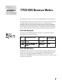
6IZIRYI1IXIVMRK
Details specific to the revenue-class 7700 ION -RMANSI and –RMICAN are
provided in the Appendix.
'SRXIRXW
4S[IV7XEVX M
-RXVSHYGXMSR The 7700 ION is Factory-Configured and Ready to Operate ..................................... 1-2
What’s New in Firmware Version 7700V200................................................................. 1-2
The 7700 ION in a Power Monitoring System.............................................................. 1-3
Data Display and Analysis Tools ...................................................................................... 1-4
Communications Options .................................................................................................. 1-4
Input/Output................................................................................................................... .... 1-5
Using this Guide ............................................................................................................... . 1-5
Before You can Use this Guide .......................................................................................... 1-6
Getting More Information................................................................................................ 1-6
(MWTPE]MRK(EXE Displaying Data with PEGASYS Vista 2.0 .................................................................... 2-2
Summary of Data Provided................................................................................................ 2-2
Displaying Data if PEGASYS is not Fully Configured ................................................... 2-3
Real-Time Measurements ................................................................................................... 2-4
Power Quality Data............................................................................................................. 2-5
Energy & Demand............................................................................................................... 2-7
Setpoints ............................................................................................................................... 2-8
Digital Inputs ....................................................................................................................... 2-9
Displaying Additional Data in Vista............................................................................... 2-10
Displaying Data with PowerView ................................................................................ 2-11
Summary of Data Provided.............................................................................................. 2-11
PowerView’s Data Screens Mode.................................................................................... 2-12
Selecting Different Display Screens ................................................................................ 2-12
Displaying Data with the MGT..................................................................................... 2-13
Data Display Screens......................................................................................................... 2-13
Interpreting Numbers in Numeric Displays.................................................................. 2-14
Bar Graph Displays ........................................................................................................... 2-15
Trend Displays................................................................................................................... 2-16
Harmonics Displays .......................................................................................................... 2-16
Display Screens Available under SETUP ....................................................................... 2-17
Complete List of Factory-Configured Measurements and Functions .................... 2-19
Energy & Demand Framework........................................................................................ 2-19
Min/Max Framework....................................................................................................... 2-20
Historic Data Logging Framework ................................................................................. 2-23
Harmonics Logging Framework ..................................................................................... 2-25
Power Quality Monitoring Framework.......................................................................... 2-26
Setpoint Framework.......................................................................................................... 2-28
Digital Inputs Framework ................................................................................................ 2-29
Real Time Measurements (Core Modules)..................................................................... 2-30
LLL
1EOMRK'SRJMKYVEXMSR'LERKIW r
Configuration Tools ..........................................................................................................3–2
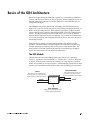
Basics of the ION Architecture ........................................................................................3–3
The ION Module..................................................................................................................3–3
ION Registers.......................................................................................................................3–4
Making ION Configuration Changes ............................................................................3–4
Configuring the 7700 ION with ION Designer ............................................................3–5
The Main 7700 ION Configuration Screen....................................................................3–5
Using ION Designer to Change Setup Registers .............................................................3–5
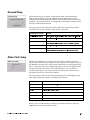
Basic Configuration ...........................................................................................................3–7
Communications Setup.....................................................................................................3–8
Communications Protocols ................................................................................................3–8
Demand Setup ....................................................................................................................3–9
Meter Clock Setup .............................................................................................................3–9
Power Quality Setup .......................................................................................................3–10
Data Logging Setup .........................................................................................................3–11
Changing the Parameters that are Logged.....................................................................3–11
Setpoint Setup ..................................................................................................................3–12
Advanced Setup ...............................................................................................................3–12
Third-Party Protocols ......................................................................................................3–13
Configuring a Communications Protocol.......................................................................3–13
Configuring the 7700 ION with PowerView...............................................................3–15
Using the PowerView Interface.....................................................................................3–15
PowerView’s Setup Screens Mode ..................................................................................3–15
PowerView’s Basic and Advanced ION Setup Modes .................................................3–16
Determining Which Modules to Configure ...................................................................3–17
Configuring the 7700 ION with the MGT ...................................................................3–18
The MGT’s Setup Menus ...............................................................................................3–18
Using the MGT’s Buttons .................................................................................................3–19
Quick Setup.......................................................................................................................3–21
Parameter Reset ................................................................................................................3–23
Configure ION..................................................................................................................3–24
9WMRK%HZERGIH*IEXYVIW r
Customizing the 7700 ION’s Operation.........................................................................4–2
ION Details .........................................................................................................................4–3
Module Linking Restrictions..............................................................................................4–3
The Not Available Value ....................................................................................................4–4
Core Modules and Fixed Module Links ...........................................................................4–4
ION Register Details ...........................................................................................................4–4
Timing Considerations in the 7700 ION........................................................................4–6
Time-Sensitive Modules .....................................................................................................4–7
Sequence of Module Execution..........................................................................................4–7
LY
ION Event Priority Groups ..............................................................................................4–8
External ION events ............................................................................................................4–9
Dismantling the Factory Configuration.........................................................................4–9
Checking the Processor Power Level................................................................................4–9
Deleting Factory-Configured Functions.........................................................................4–10
Adding and Linking Modules in ION Designer........................................................4–11
Creating New Modules.....................................................................................................4–12
Deleting Modules ..............................................................................................................4–12
Linking Modules ...............................................................................................................4–13
Editing Existing Frameworks ..........................................................................................4–14
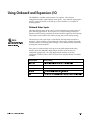
Using Onboard and Expansion I/O ..............................................................................4–15
Onboard Status Inputs ......................................................................................................4–15
Auxiliary Analog Inputs...................................................................................................4–16
I\O Expansion Boards ......................................................................................................4–16
Specifying a Port in an ION Module...............................................................................4–19
Using the Modbus RTU Protocol ..................................................................................4–20
The 7700 ION’s Factory Modbus Configuration ...........................................................4–20
Modbus Slave Module Settings .......................................................................................4–21
Modbus Slave Module Parameter Mapping ..................................................................4–22
Importing Data using Modbus RTU ...............................................................................4–24
Using the DNP 3.0 Protocol............................................................................................4–25
The 7700 ION’s Factory DNP 3.0 Configuration ...........................................................4–25
DNP Slave Export Module Settings ................................................................................4–26
DNP Options Module Settings ........................................................................................4–27
Importing Data using DNP 3.0 ........................................................................................4–27
Using Power Measurement’s EtherGate Protocol ......................................................4–28
Communicating Through the 7700 ION ..........................................................................4–28
Communicating To the 7700 ION ....................................................................................4–29
Specifying the Protocol and the IP Port Number ..........................................................4–30
Using the 7700 ION in LonWorks Networks .............................................................. 4–31
PEGASYS Configuration Updates are Not Required ...................................................4–31
Configuring the LonWorks Port......................................................................................4–31
Using Time Synchronization .........................................................................................4–32
Time Synchronization Accuracy......................................................................................4–32
Communications Ports and Protocols Used ..................................................................4–33
Time Synchronization using PEGASYS..........................................................................4–34
Time Synchronization using a GPS Receiver .................................................................4–35
Supported GPS Receivers .................................................................................................4–35
Creating Custom MGT Displays................................................................................... 4–37
Overview of MGT Button Configuration....................................................................4–37
Using the MGT Display Formats ..................................................................................4–38
Y
8IGLRMGEP6IJIVIRGI r
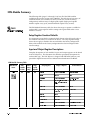
ION Module Summary .....................................................................................................5–2
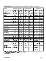
Measurements...................................................................................................................5–13
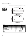
kW Measurement Accuracy............................................................................................5–14
High-Speed Measurements During Fault ...................................................................5–14
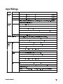
Input Ratings ....................................................................................................................5–15
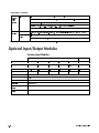
Optional Input/Output Modules ..................................................................................5–16
Analog Input Modules......................................................................................................5–16
Analog Output Modules...................................................................................................5–17
Digital Input Modules.......................................................................................................5–17
Digital Input Dry Contact Modules ................................................................................5–18
Thermocouple Input Modules .........................................................................................5–18
RTD Input Modules ..........................................................................................................5–18
Digital Output Modules ...................................................................................................5–19
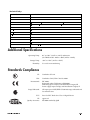
Additional Specifications ...............................................................................................5–21
Standards Compliance ....................................................................................................5–21
Ordering Information......................................................................................................5–22
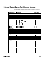
External Output Device Part Number Summary........................................................5–25
Warranty and Registration .............................................................................................5–26
Product Return Procedure ..............................................................................................5–26
Registration .......................................................................................................................5–27
%44)2(-<%-326IZIRYI1IXIVW%
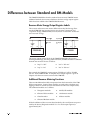
Differences between Standard and RM Models ......................................................... A-2
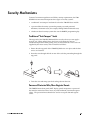
Security Mechanisms ....................................................................................................... A-3
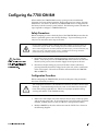
Configuring the 7700 ION-RM ....................................................................................... A-5
Safety Precautions .............................................................................................................. A-5
Configuration Procedure................................................................................................... A-5
CT & PT Selection............................................................................................................... A-6
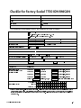
Checklist for Factory-Sealed 7700 ION-RMICAN ...................................................... A-7
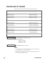
Data Recorder #1 (Sealed)................................................................................................ A-8
-RHI\ -
YL
-RXVSHYGXMSR
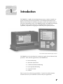
The 7700 ION is a highly advanced digital power meter, suited to virtually any
power monitoring and control application. This Intelligent Electronic Device
(IED) can take the place of numerous transducers, meters and control circuits in
your power monitoring system. The 7700 ION provides true RMS measurements
of voltage, current, power and energy, complemented by extensive I/O
capabilities, comprehensive logging, and advanced power quality functions.
The 7700 ION with the Modular Graphics Terminal
The 7700 ION can be used effectively in numerous supply side and demand side
operations. Some common applications of the 7700 ION are:
♦
Revenue Metering
♦
Substation Automation
♦
Commercial/Industrial Metering
♦
Power Quality Monitoring
♦
Capacitor Control
♦
SCADA
These are just a few of the many possibilities. Contact Power Measurement
Customer Service if you would like assistance with your application.
8LI-32MW*EGXSV]'SRJMKYVIHERH6IEH]XS3TIVEXI
Although the 7700 ION is fully customizable, it is shipped from the factory with
many functions pre-configured. Once installation and basic setup are preformed,
all of the basic measurements, energy calculations and recording functions are
ready to operate, right out of the box. Many users will find that the factory
configuration will serve their purposes without performing any additional
configuration.
;LEX
W2I[MR*MVQ[EVI:IVWMSR:
Firmware version 7700V200 offers many new and enhanced features, including
new power quality functions, new communications and I/O options, and more
ION module types for advanced applications. PEGASYS version 2.0 includes
several enhancements that make the 7700 ION easier to set up and use.
(EXE(MWTPE]ERH(IZMGI'SRJMKYVEXMSR-QTVSZIQIRXW
The most significant change to the 7700 ION in the V200 release is found when
you display data or perform configuration functions with PEGASYS Vista, ION
Designer and the MGT.
The data measured by the 7700 ION is now easier to access and interpret in
PEGASYS Vista. A new set of user diagrams, included on the PEGASYS 2.0
release CD, group most of the factory-configured functions onto five main
screens for real-time measurements, power quality monitoring, energy and
demand calculations, setpoints and digital input status.
Both ION Designer software and the MGT have been updated to provide easier
access to setup functions.
4S[IV5YEPMX]*IEXYVIW
7700V200 firmware provides enhanced power quality monitoring functions. The
device now uses a nominal system voltage level to quantify power quality events
such as sags, swells and transients. Both the Sag/Swell module and the Transient
module have been improved, and the display of real-time and logged power
quality events is incorporated into the standard PEGASYS Vista user diagrams.
2I['SQQYRMGEXMSRWERH-33TXMSRW
New or improved communications and I/O features include:
♦
The XPRESS CARD supports the DNP 3.0 protocol on either RS-485 port (only
one port can be configured to use DNP 3.0 at any one time).
♦
New protocols and functions provide high-accuracy time synchronization
using GPS receivers. PEGASYS time synchronization is also improved.
♦
The XPRESS CARD supports two independent EtherGate gateways.
♦
Support is added for various types of thermocouple inputs.
♦
The new Alert module provides automatic dial-out to PEGASYS and paging
systems in response to user-specified conditions.
-3297)6
7+9-()
2I[-321SHYPIW
New ION modules are included that provide more options to the advanced user:
♦
DNP Import, Export and Options modules for DNP 3.0 communications.
♦
Relative Setpoint modules for monitoring a variable source input.
♦
Convert modules for converting different types of data.
♦
Feedback modules for creating circular linkages in ION frameworks.
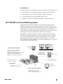
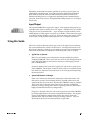
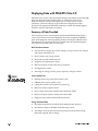
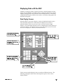
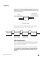
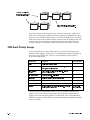
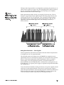
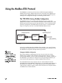
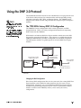
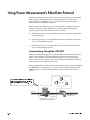
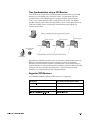
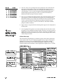
8LI-32MRE4S[IV1SRMXSVMRK7]WXIQ
Applications that include the 7700 ION, or any other IED, typically require
additional equipment. Display and analysis software tools are almost always
used to manage, interpret and distribute the data measured or logged by an IED.
Usually there are a variety of tools used, and often these tools are connected
using different communications standards and protocols. In many cases, an IED
must also provide control capabilities and device-level data sharing.
The 7700 ION can adapt to almost any situation. Advanced communications
allow data to be shared simultaneously across multiple networks, expandable
I/O provides additional monitoring and control capabilities, and a variety of
display and analysis tools can be used to monitor your power system. This
User’s Guide discusses the 7700 ION as it is most commonly used — as a part of
a complete power monitoring system.
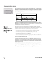
Communications Options
up to five concurrent connections
RS-232 and high-speed RS-485
10Base-T and 10Base-FL (fiberoptic) Ethernet
LonWorks FTT10 LonTalk support
ION, Modbus RTU and DNP3.0 protocols
EtherGate RS-485/Ethernet gateway
distributed
PEGASYS
software
components
PowerView
software
corporate network
Display and
Analysis Tools
MGT
field display unit
Modbus, DNP3.0 and
Lonworks software tools
pulses, breaker status,
analog transducer signals
Input/Ouput
MV-90
analog signals,
energy pulses, control signals
UTS MV-90TM
revenue metering
software
Power System Connections
phase voltage, phase current
and neutral current from Wye,
Delta or single-phase power systems
-2863(9'8-32
(EXE(MWTPE]ERH%REP]WMW8SSPW
The 7700 ION integrates seamlessly with the display and analysis software
available from Power Measurement. The data acquired by the 7700 ION can be
used in a variety of systems; however, Power Measurement software is designed
to make use of the advanced capabilities the unit provides.
4S[IV1IEWYVIQIRX
W4)+%7=77SJX[EVI
You will get the most out of the 7700 ION using Power Measurement’s PEGASYS
software suite. When PEGASYS is used, the 7700 ION becomes part of a fully
networked information system, together with other Power Measurement IEDs
and local and wide-area computer networks. PEGASYS provides tools for
managing your power monitoring network, analyzing real-time and logged data,
generating power system reports, and creating custom functionality at the IED
level. PEGASYS is recommended for all power monitoring systems where
advanced analysis and control capabilities are required.
4S[IV1IEWYVIQIRX
W4S[IV:MI[7SJX[EVI
The 7700 ION can be installed in power monitoring systems that use Power
Measurement’s PowerView software. PowerView provides real-time and
available logged data display and analysis features, and complete device
configuration capabilities. PowerView provides a low-cost solution for smaller
power system where the advanced features of PEGASYS are not required.
8LI-32
W1SHYPEV+VETLMGW8IVQMREP
Local monitoring and standalone applications are facilitated by the 7700
ION’s front-panel interface, the Modular Graphics Terminal (the MGT).
The MGT combines real-time display features with limited device
configuration functions.
The MGT is often used in combination with a PEGASYS or PowerView
system, providing an interface for field personnel.
8LMVH4EVX]8SSPW
The 7700 ION can be integrated into various industry-standard networks. Data
that is measured by the unit can be made available to other devices using
Modbus RTU, DNP 3.0 and LonWorks protocols. Data from devices on these
networks can also be imported into the 7700 ION. With these advanced
communications functions, the power of the 7700 ION can be utilized in most
existing power monitoring systems. Any data display and analysis software that
works with Modbus RTU, DNP 3.0 or LonWorks devices will also work with the
7700 ION (specific communications options are required for LonWorks).
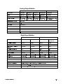
'SQQYRMGEXMSRW3TXMSRW
The standard 7700 ION has a single RS-232/RS-485 communications port capable
of data rates up to 19,200 bps. The optional XPRESS CARD provides two
additional high-speed RS-485 ports (data rates up to 115,200 bps) and a 10Base-T
Ethernet port. A 10Base-FL fiberoptic Ethernet port and an FTT10 LonWorks
port are available as options on the XPRESS CARD.
-3297)6
7+9-()
Depending on the hardware options purchased, up to five separate ports can
communicate simultaneously. Power Measurement’s ION Protocol, Modbus
RTU, DNP 3.0, LonTalk and Power Measurement’s EtherGate Protocol (an
Ethernet/RS-485 gateway) are supported, depending on the communications
port used. Refer to the section “Using Onboard and Expansion I/O” in Chapter
4 for details.
-RTYX3YXTYX
The standard 7700 ION has eight status inputs. Four optional analog inputs are
available on the meter to monitor AC or DC signals. Additional I/O is available
using one or two expansion boards — up to 15 input or output modules can be
added (digital or analog inputs or outputs are available). Some restrictions apply
to number of analog modules you can use, due to the power they require. Refer
to the section “Using On-Board and Expansion I/O” in Chapter 4 for details.
9WMRKXLMW+YMHI
This User’s Guide is directed at three types of user: the typical user or operator,
the system administrator, and the advanced user. You might not fit into any of
these groups directly, or perhaps you are both an operator and an administrator.
These user classifications are intended to make this guide easier to navigate.
♦
8]TMGEP9WIVSV3TIVEXSV
Most users will simply want to display the data provided by the factoryconfigured 7700 ION. These users want fast access to data through the front
panel, PEGASYS software, PowerView software or a third-party protocol
such as Modbus RTU.
Chapter 2 addresses the needs of the typical user who wants to get data out
of the 7700 ION. This chapter assumes that the reader is not concerned with
how the device functions; instead the focus is on accessing and interpreting
the data provided.
♦
7]WXIQ%HQMRMWXVEXSVSV1EREKIV
Some users will need to make minor adjustments so that their meters “fit”
their power systems: data recording intervals, demand sub-intervals and
other parameters may need to be set before the 7700 ION’s setup is complete.
These users will use the front panel, PowerView software or PEGASYS
software to change settings in the device’s operating software. (PEGASYS is
highly recommended for device configuration.)
Chapter 3 is directed at the user who wants to get more out of the 7700 ION
by making adjustments to its factory-configured functionality. This chapter
focuses on the different configuration changes that can be made with
minimal effort, and what effects each type of setting will have. Very few
details about the device’s internal operation are provided.
-2863(9'8-32
♦
%HZERGIH9WIVSV7]WXIQW-RXIKVEXSV
Advanced users may want to make use of the flexibility and power provided
by the device’s operating software. These users will need to become familiar
with the device’s operating software, the ION Architecture, and the
PEGASYS tools used to customize the device’s operation.
Chapter 4 is useful for the advanced user who wants to become familiar with
the device’s internal operation and its more sophisticated capabilities. This
chapter is designed to facilitate different applications by providing
background information and detailed functional descriptions — specific
applications are only discussed to illustrate a particular function.
Configuration instructions for particular applications can be found in Power
Measurement Application Notes, available from Power Measurement
Customer Service.
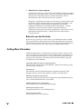
&IJSVI=SYGER9WIXLMW+YMHI
By the time you are ready to use this Guide, your 7700 ION should be installed,
basic setup should have been performed, and communications/basic operation
should have been verified. If the unit is not yet installed and operational, refer to
the 7700 ION Installation & Basic Setup Instructions shipped with the meter.
+IXXMRK1SVI-RJSVQEXMSR
Additional information is available from Power Measurement. Check our web
site at www.pml.com, contact your local Power Measurement representative, or
contact Power Measurement directly. (Contact information is provided on the
first page of this document.) Documents related to the installation, operation
and application of the 7700 ION:
7700 ION Installation & Basic Setup Instructions
This brief guide is shipped with each 7700 ION. It details the mounting, wiring
and basic setup of the device.
ION Reference
This reference contains detailed descriptions of the ION architecture, ION
Designer software, and all of the modules available in each ION device.
PEGASYS 2.0 Administrator’s Guide
This guide explains the installation and configuration of the PEGASYS software
suite. Advanced PEGASYS tools are described.
PEGASYS ION Designer On-line Help
This describes how to use PEGASYS ION Designer.
PEGASYS Vista User’s Guide
This guide describes how to use PEGASYS Vista.
PowerView On-line Help
This describes how to use PowerView.
-3297)6
7+9-()
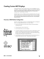
(MWTPE]MRK(EXE
The 7700 ION is shipped from the factory with a comprehensive configuration.
Most users will find that the factory configuration suits their needs entirely.
This chapter describes how to view the data that is measured and logged by the
factory-configured 7700 ION using PEGASYS Vista software, PowerView
software and the MGT front-panel interface.
The 7700 ION’s factory configuration also includes some data that does not
appear by default in PEGASYS Vista, PowerView or on the MGT. Further, the
factory configuration makes several power, energy and demand parameters
available through the Modbus RTU protocol. A list of available data that does
not appear in PEGASYS Vista, PowerView or on the MGT is presented near the
end of this chapter, and how to view it is briefly discussed.
-RXLMW'LETXIV
♦
Displaying Data with PEGASYS Vista 2.0......................................................... 2-2
Summary of Data Provided ............................................................................. 2-2
Common Diagram Elements ........................................................................... 2-3
Displaying Data if PEGASYS is not Fully Configured................................. 2-3
Real-Time Measurements................................................................................. 2-4
Power Quality Data........................................................................................... 2-5
The Energy & Demand Calculations .............................................................. 2-7
Setpoints ............................................................................................................. 2-8
Digital Inputs ..................................................................................................... 2-9
Displaying Additional Data in Vista ............................................................ 2-10
♦
Displaying Data with PowerView.................................................................... 2-11
Summary of Data Provided ........................................................................... 2-11
PowerView’s Data Screens Mode ................................................................. 2-12
Selecting Different Display Screens .............................................................. 2-12
The PowerView Data Filter............................................................................ 2-12
♦
Displaying Data with the MGT......................................................................... 2-13
Data Display Screens ...................................................................................... 2-13
Interpreting Numbers in Numeric Displays ............................................... 2-14
Bar Graph Displays ......................................................................................... 2-15
Trend Displays................................................................................................. 2-16
Harmonics Displays........................................................................................ 2-16
Display Screens Available under SETUP..................................................... 2-17
♦
Complete List of Factory-Configured Measurements and Functions ......... 2-19
(MWTPE]MRK(EXE[MXL4)+%7=7:MWXE
PEGASYS Vista version 2.0 is the premiere display and analysis tool for the 7700
ION and other Power Measurement IEDs. A standard set of Vista User
Diagrams displays real-time and logged data for various power system
parameters. Interactive objects are provided on the diagrams that allow
operators with appropriate PEGASYS authority to enable and disable logging
functions and reset cumulative parameters.
7YQQEV]SJ(EXE4VSZMHIH
The standard set of five Vista diagrams included with PEGASYS 2.0 display a
variety of the data measured and logged by the factory-configured 7700 ION.
Some of the diagrams include grouping windows that display additional data.
The following list summarizes the data available from the standard diagrams;
more detail is provided in the next few pages.
6IEP8MQI1IEWYVIQIRXW
238)
0DQ\ RI WKH 9LVWD GLDJUDPV
DOVRSURYLGHLQWHUDFWLYH FRQWURO
DQGSDUDPHWHUUHVHWIXQFWLRQV
♦
Line-to-neutral voltages, line-to-line voltages, average L-N and L-L voltages
and voltage unbalance level
♦
Phase currents and average current
♦
Phase kW, total kW, kVAR and kVA
♦
Frequency and signed power factor
♦
Min/max display of each of the above parameters
♦
All logged meter events
♦
Trend logs of voltage, current, power, frequency and power factor
4S[IV5YEPMX](EXE
♦
Running total of sag/swell and transient events
♦
CBEMA plot of power quality events
♦
Captured waveforms and sequence-of-events log
♦
Manual waveform capture control
♦
Phase voltage and current total harmonic distortion (THD)
♦
Min/max display of phase voltage and current THD
♦
Logged average and maximum THD and K factor
)RIVK](IQERH(EXE
♦
Real-time and peak kW, kVAR and kVA sliding window demand
♦
Real-time net kWh, net kVARh and kVAh energy values
♦
Trend log of all of the above parameters, plus power factor lead and lag,
imported, exported and net energy
-3297)6
7+9-()
7IXTSMRXW
♦
Interactive monitoring of kW demand, phase current, and voltage
unbalance conditions, with annunciation when user-specified upper limit is
exceeded
♦
Real-time display of kW demand, phase current, and voltage unbalance
(MKMXEP-RTYXW
♦
Monitoring of the 7700 ION’s eight on-board status inputs
♦
Status change counter for each input
'SQQSR(MEKVEQ)PIQIRXW
238)
! c#
H¦c?H LI \RX QHHG KHOS
5HIHU WR WKH
XVLQJ9LVWD
Each diagram shows the name of the meter, the time on the meter’s clock, and
the type of meter. The five main diagrams also provide buttons that let you
jump to other diagrams. Double-click any of the buttons near the top righthand corner to jump to the associated diagram (this is illustrated in the RealTime Measurements section below).
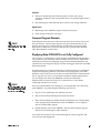
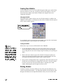
(MWTPE]MRK(EXEMJ4)+%7=7MWRSX*YPP]'SRJMKYVIH
The PEGASYS 2.0 Administrator’s Guide, shipped with PEGASYS 2.0, provides a
set of guidelines that should be followed during commissioning. If PEGASYS
2.0 has been installed and configured using the recommended guidelines, the
standard Vista user diagrams display real-time and logged data from your 7700
ION automatically.
238)
,I \RX FDQ·W GLVSOD\ GDWD LQ
3(*$6<6 9LVWD DQG \RX GRQ·W
If commissioning has not been completed (or if commissioning was performed
without following the guidelines) some effort may be required to view 7700
ION data in Vista 2.0. If you are not able to run the PEGASYS Communications
Server, Log Server or Vista, you will need to complete commissioning before
you can display data from your 7700 ION. Contact your PEGASYS
Administrator or refer to the PEGASYS 2.0 Administrator’s Guide before
continuing with this User’s Guide.
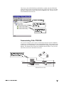
If you can run PEGASYS Vista and log on, you can probably access data from
your 7700 ION. Try performing the following steps in Vista:
KDYH /HYHO DXWKRULW\ FRQWDFW
\RXU3(*$6<6DGPLQLVWUDWRU
1.
Log on to Vista with Supervisor authority (Level 5).
2.
Select Generate Network Diagram from the File menu.
3.
In the Network Diagram, double-click the Workstation icon corresponding
to the computer that communicates with the 7700 ION. A new diagram
with all available IEDs appears.
4.
Double-click the icon for the 7700 ION. The Real-Time diagram appears,
and live data should appear within moments.
You should now be able to move around through the various diagrams and
view real-time and logged data.
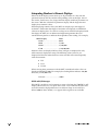
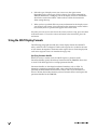
(-740%=-2+(%8%
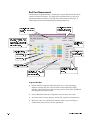
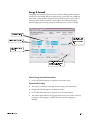
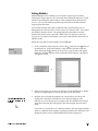
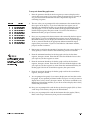
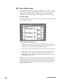
6IEP8MQI1IEWYVIQIRXW
The Real-Time diagram includes a simple power system illustration that shows
various real-time parameters. The diagram also includes links to a min/max
parameter display, the meter’s event log and various historical data logs. A
control object is provided for disabling/enabling historic data.
'RXEOHFOLFN DQ\ RI WKHVH
'RXEOHFOLFN WKLV EXWWRQ
EXWWRQV WR MXPS WR WKH
WR UHWXUQ WR WKH 1HWZRUN
FRUUHVSRQGLQJGLDJUDPV
'LDJUDP
7KLV
DUHD
UHSUHVHQWV
\RXU
SRZHUV\VWHP$%DQG&DUH
WKH SKDVHV DQG 1 LV QHXWUDO
'RXEOHFOLFN WR
9ROWDJH XQEDODQFH LV VKRZQ
VHH WKH PHWHU·V
EHORZWKHOLQHGLDJUDP
(YHQWORJ
/LQHWROLQHYROWDJHV
'RXEOHFOLFN DQ\
RI WKHVH EXWWRQV
WRVHHGDWDORJV
3KDVHFXUUHQW
3KDVHSRZHU
/LQHWRQHXWUDOYROWDJHV
'RXEOHFOLFN WKLV REMHFW
HQDEOH
'RXEOHFOLFN
WR
VHH
WKH
RU
GLVDEOH
WR
GDWD
ORJJLQJ
PLQPD[ VFUHHQ 0LQPD[
UHVHWLVDYDLODEOHKHUH
0SRKXIVQ1MR1E\
♦
Double-click the Long-term Min/Max object to see a Vista grouping
window showing min/max values for line-to-line and line-to-neutral
voltages, voltage unbalance, phase currents, power values (kVA, kVAR and
kW), frequency and power factor.
♦
Level 3 PEGASYS authority is required to reset the min/max values.
♦
To return to the real-time diagram, use the File, Up One Level menu item.
♦
Min/max values are valid from the time the meter was powered up, or
valid from the time the last reset was performed.
-3297)6
7+9-()
,MWXSVMG(EXE0SKKMRK)REFPI
♦
The Log Server must be running to view historical data.
♦
Historic data logging is enabled by default.
♦
Level 3 PEGASYS authority is required to use the control object.
♦
The control object indicates the logging enable status: the switch is in the up
position (1) when logging is enabled, and down (0) when logging is
disabled.
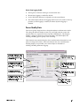
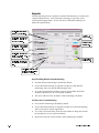
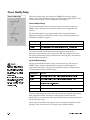
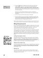
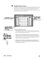
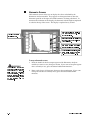
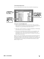
4S[IV5YEPMX](EXE
The Power Quality diagram shows voltage disturbance and harmonics details.
The voltage disturbance display counts sag/swell and transient events, and
provides links to a sequence-of-events log and a CBEMA plot. The diagram
includes a trigger for manual waveform recording, and control objects for
enabling/disabling power quality event recording.
The harmonics measurement display shows total harmonic distortion for each
phase of voltage and current. Links to harmonics min/max and harmonics
trending displays are provided, and a control object is included for
enabling/disabling harmonics logging.
&KHFN KHUH WR VHH KRZ PDQ\
VDJVZHOO DQG WUDQVLHQW HYHQWV
7KLVDUHD VKRZV SHU SKDVH
KDYH RFFXUUHG VLQFH SRZHUXS
YROWDJHDQGFXUUHQW7+'
RUWKHODVWUHVHW
'RXEOHFOLFN WKHVH REMHFWV WR
'RXEOHFOLFN WKLV REMHFW WR
VHH GLVWXUEDQFH GHWDLOV LQ D
YLHZ KDUPRQLFV PLQPD[
&%(0$ SORW RU VHTXHQFHRI
GDWD 0LQPD[ UHVHW LV
HYHQWVORJ
DYDLODEOHKHUH
'RXEOHFOLFNWKLVREMHFWWR
'RXEOHFOLFN WKLV REMHFW
PDQXDOO\UHFRUGDZDYHIRUP
WR YLHZ WKH KDUPRQLFV
GDWDORJ
'RXEOHFOLFN WKHVH REMHFWV WR
HQDEOH
RU
GLVDEOH
SRZHU
TXDOLW\ HYHQW GHWHFWLRQ DQG
ZDYHIRUPUHFRUGLQJ
'RXEOHFOLFN WKLV REMHFW
WR
HQDEOH
RU
GLVDEOH
KDUPRQLFVORJJLQJ
(-740%=-2+(%8%
:SPXEKI(MWXYVFERGI'SYRXIV6IWIX
♦
Level 3 PEGASYS authority is required to reset the power quality event
counter, the manual waveform trigger, and the control objects.
(MWXYVFERGI(IXEMPW
♦
The Log Server must be running to view the CBEMA plot or sequence-ofevents data.
,EVQSRMGW1IEWYVIQIRXW
♦
Total Harmonics Distortion (THD) is displayed as a percentage of phase
measurements.
0SRKXIVQ1MR1E\
♦
Double-click the Long-term Min/Max object to see a Vista grouping
window showing min/max values for phase voltage and current THD.
♦
Level 3 PEGASYS authority is required to reset the min/max values.
,EVQSRMGW8VIRHMRK
♦
The Log Server must be running to view the logged harmonics data.
♦
Harmonics data logging is enabled by default.
♦
Level 3 PEGASYS authority is required to use the control object.
♦
The control object indicates the logging enable status: the switch is in the up
position (1) when logging is enabled, and down (0) when logging is
disabled.
-3297)6
7+9-()
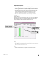
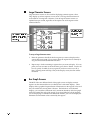
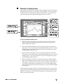
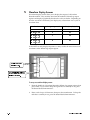
)RIVK](IQERH
The Energy & Demand diagram shows the real-time sliding window demand
for kW, kVA, and kVAR, and the real-time energy values kWh net, kVARh net
and kVAh. Peak demand is displayed for kW, kVAR and kVA, and a link to a
demand profile trend is provided. Control objects for enabling/disabling
demand logging and resetting energy and demand values are also included.
1HWHQHUJ\YDOXHV
'RXEOHFOLFN
WKLV
REMHFW WR VHH WKH
6OLGLQJZLQGRZGHPDQG
HQHUJ\ GHPDQG
ORJ
3HDN VOLGLQJ ZLQGRZ
GHPDQG
'RXEOHFOLFNWKLVREMHFWWR
HQDEOH RU GLVDEOH HQHUJ\
DQGGHPDQGORJJLQJ
(IQERH)RIVK]ERH4IEO(IQERH6IWIX
♦
Level 3 PEGASYS authority is required to reset these values.
(IQERH4VSJMPI8VIRHMRK
(-740%=-2+(%8%
♦
The Log Server must be running to view the energy and demand log.
♦
Energy and demand logging is enabled by default.
♦
Level 3 PEGASYS authority is required to use the control object.
♦
The control object indicates the logging enable status: the switch is in the up
position (1) when logging is enabled, and down (0) when logging is
disabled.
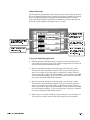
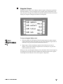
7IXTSMRXW
The Setpoints diagram uses setpoints to monitor kW demand, over current and
voltage unbalance levels. Vista annunciates warnings if any of the values
exceed specified upper limits. (Users with Level 3 PEGASYS authority can
define the setpoint limits.)
'RXEOHFOLFNWKLVREMHFWWR
VHWWKHN:GHPDQGOLPLW
0RQLWRU
HQDEOH
RU
GLVDEOH
N:
GHPDQGKHUH
'RXEOHFOLFN WKLV REMHFW WR
N:
GHPDQGPRQLWRULQJ
0RQLWRU SKDVH
FXUUHQWVKHUH
'RXEOHFOLFN WKHVH REMHFWV
WR
VHW
WKH
RYHUFXUUHQW
OLPLWVIRUHDFKSKDVH
'RXEOHFOLFN WKLV REMHFW WR
HQDEOH RU GLVDEOH RYHU
FXUUHQWPRQLWRULQJ
0RQLWRUYROWDJH
XQEDODQFHKHUH
'RXEOHFOLFN WKLV REMHFW WR
VHW WKH YROWDJH XQEDODQFH
OLPLW
'RXEOHFOLFN WKLV REMHFW WR
HQDEOH RU GLVDEOH YROWDJH
XQEDODQFHPRQLWRULQJ
3ZIVO;7PMHMRK;MRHS[(IQERH1SRMXSVMRK
♦
Over kW demand monitoring is disabled by default.
♦
Level 3 PEGASYS authority is required to enable over kW demand
monitoring, and to set the kW demand upper limit.
♦
To set the upper kW demand limit, enter the total number of kW that
should be considered as an over demand condition.
♦
The status will read “Not Available” when monitoring is disabled.
4IV4LEWI3ZIV'YVVIRX1SRMXSVMRK
♦
Over current monitoring is disabled by default.
♦
Level 3 PEGASYS authority is required to enable over current monitoring,
and to set the phase current upper limit.
♦
To set the over current limits, enter the total number of Amps that should
be considered as an over current condition.
♦
Each status will read “Not Available” when monitoring is disabled.
-3297)6
7+9-()
:SPXEKI9RFEPERGI1SRMXSVMRK
♦
Over voltage unbalance monitoring is disabled by default.
♦
Level 3 PEGASYS authority is required to enable over voltage unbalance
monitoring, and to set the voltage unbalance upper limit.
♦
To set the upper limit for voltage unbalance, enter the percentage of the
average voltage measurement that will be considered as a voltage
unbalance condition if it is exceeded by the voltage on any phase.
♦
The status will read “Not Available” when monitoring is disabled.
(MKMXEP-RTYXW
The Digital Inputs diagram monitors the eight status inputs on the 7700 ION.
The status of each input (ON or OFF), and the number of times the status has
changed is displayed. The status change counter can be reset.
7KHVWDWXVRIHDFKLQSXW
'RXEOHFOLFN WKLV REMHFW WR
UHVHW WKH VWDWXV FKDQJH
FRXQWHU
7KHQXPEHURIWLPHVHDFK
LQSXWKDVFKDQJHGVWDWXV
7XEXYW
♦
The 7700 ION’s status inputs are de-energized when the meter is poweredup, so each status will initially be OFF.
6IWIX
♦
(-740%=-2+(%8%
Level 3 PEGASYS authority is required to reset the status counter.
(MWTPE]MRK%HHMXMSREP(EXEMR:MWXE
The factory-configured 7700 ION measures and calculates additional data that is
not presented in the standard Vista diagrams. This data can be added to the
standard diagrams, or new diagrams can be created. Any data that the 7700
ION measures or logs can be displayed on a Vista diagram.
PEGASYS Supervisor authority (Level 5) is required to create and configure
new diagrams. Refer to the PEGASYS Vista User’s Guide for details on creating
Vista User Diagrams. If you don’t have Level 5 authority, contact your
PEGASYS administrator for assistance.
Refer to the section “Complete List of Factory-Configured Measurements and
Functions” near the end of this chapter. This list indicates what data is not
displayed on the standard Vista diagrams, but is available from the factoryconfigured 7700 ION.
-3297)6
7+9-()
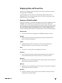
(MWTPE]MRK(EXE[MXL4S[IV:MI[
PowerView for Windows 95/NT displays many of the parameters measured
and logged by the 7700 ION.
The data displays in PowerView are considerably different than those in
PEGASYS Vista. This section describes how to view data in PowerView, and
which data screens are available.
7YQQEV]SJ(EXE4VSZMHIH
PowerView includes a set of tables that display data from the 7700 ION version
7700V200. The available data is grouped into 27 data screens: 20 for data
recorders and seven for other logs and measurements. Many of the data screens
have multiple tabs that display additional data. The following list summarizes
the data available from the standard data screens; see the “Complete List of
Factory Configured Measurements and Functions” near the end of this chapter.
(EXE6IGSVHIVW
♦
Any recorded data that is logged by the 7700 ION’s 20 data recorders
(IQERH
♦
Sliding window demand, predicted demand and thermal demand for
power and current parameters
)REFPIW
♦
Logging enable switches for min/max values, energy, historic data,
demand, harmonics, sag/swell, transients, and waveforms.
)ZIRX
♦
The meter’s event log (all events logged by the meter)
,EVQSRMGW
♦
Phase voltage and current total harmonic distortion; phase voltage and
st
th
current harmonic distortion values from the 1 to the 15 ; K-factor
1E\MQYQ
♦
Maximum values and timestamps for all voltage, current, power, frequency
and harmonic distortion parameters
1MRMQYQ
♦
Minimum values and timestamps for all voltage, current, power, frequency
and harmonic distortion parameters
6IEP8MQI
♦
(-740%=-2+(%8%
Per-phase and total voltage, current, power, frequency and power factor;
total, import and export energy
7XEXYW
♦
Monitoring of over kW, over phase currents, and over voltage unbalance;
status of Digital Inputs.
;EZIJSVQ
♦
All waveform records in tabular form, waveform plotting functions
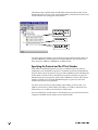
4S[IV:MI[
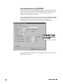
W(EXE7GVIIRW1SHI
238)
7KH 3RZHU9LHZ QHWZRUN PXVW
EH SURSHUO\ FRQILJXUHG EHIRUH
\RXFDQGLVSOD\GDWD5HIHUWR
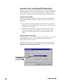
In order to view data in PowerView, you must first set the view mode to Data
Screens. This is done by selecting Data Screens from the View menu, or clicking
the Data Screens button on the toolbar (see the graphic below).
WKH3RZHU9LHZ8VHU·V*XLGHRU
Once in Data Screens mode, select a meter in the left pane, and the right pane
displays the data display groups that are available for viewing.
RQOLQHKHOSIRUDVVLVWDQFH
&OLFN
WKLV
EXWWRQ
WR
VHW
3RZHU9LHZ WR 'DWD 6FUHHQV
PRGH
'RXEOHFOLFNIROGHUVWRVHH
DGGLWLRQDOGDWDVFUHHQV
([SDQG WKH QHWZRUN WUHH WR
GLVSOD\ PHWHUV WKHQ FOLFN RQ
WKH,21
'RXEOHFOLFN D GDWD VFUHHQ
LFRQ WR YLHZ WKH DVVRFLDWHG
GDWD
7IPIGXMRK(MJJIVIRX(MWTPE]7GVIIRW
PowerView can display different data screens for different versions of the 7700
ION. New data display screens, called tables, can be downloaded from Power
Measurement’s website at www.pml.com. Save these tables in PowerView’s
\Tables\Pml7700\Default folder. Contact Power Measurement Customer
Service if you need assistance.
To change to a different set of display screens, expand the workstation tree and
right-click the meter’s icon. Select Properties from the pop-up menu. Under the
Display tab of the Device Properties dialog box, select from the list of tables
shown. Although all tables shown will allow you to display data, the Version
2.0 tables match the 7700 ION’s factory-configuration, allowing PowerView to
display a more comprehensive set of parameters.
8LI4S[IV:MI[(EXE*MPXIV
Each time you double-click a PowerView display screen icon that contains
logged data, the data filter appears. Use the data filter to select the range of
data you want to view, and press OK.
-3297)6
7+9-()
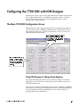
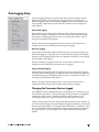
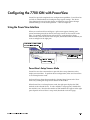
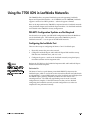
(MWTPE]MRK(EXE[MXLXLI1+8
The MGT, or Modular Graphics Terminal, provides a detailed graphics and text
display for the 7700 ION. The MGT has been configured at the factory with 24
displays showing most of the parameters measured by the meter. The factoryconfigured MGT displays numeric data screens, waveforms, trend graphs and
harmonics histograms.
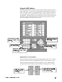
(EXE(MWTPE]7GVIIRW
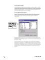
When the MGT is activated, it displays a menu of eight data display screens.
Press the button adjacent to a menu item in the display area to access a
particular display screen, or press NEXT move to the next menu of eight
displays. The SETUP button provides access to configuration screens (discussed
in the next chapter). Pressing the ESC key at any time returns you to the screen
that was last displayed. The first screen looks like this:
6HWXS VFUHHQV DUH GLVFXVVHG
LQVXEVHTXHQWFKDSWHUV
3UHVV WKH
1(;7
EXWWRQ WR
YLHZ WKH QH[W JURXS RI
HLJKWGLVSOD\VFUHHQV
3UHVV WKH EXWWRQ QH[W WR D
PHQX LWHP WR HQWHU WKH GDWD
GLVSOD\VFUHHQ
7KHNH\SDGDQGRWKHUEXWWRQV
RQ WKH 0*7 DUH QRW XVHG WR
8VH WKH
GLVSOD\ GDWD IURP WKH IDFWRU\
(6&
EXWWRQ WR H[LW
WKH VFUHHQ \RX DUH LQ DQG
FRQILJXUHGGLVSOD\V
UHWXUQ WR WKH ODVW VFUHHQ
\RXYLHZHG
7KH
67$786
OLJKW LV RQ ZKHQ
WKH0*7LVRSHUDWLRQDO
The 24 screens provided display data in a number of different formats. The
following paragraphs detail some of the important aspects of the various
display formats.
(-740%=-2+(%8%
-RXIVTVIXMRK2YQFIVWMR2YQIVMG(MWTPE]W
Eleven of the 24 display screens show up to 15 parameters in a list, with the
parameter name on the left, and the corresponding value on the right. One of
the screens, Total Power, uses a large character display with four parameters on
the screen. Both the ‘standard’ 15-parameter display and the large character
display show numeric values.
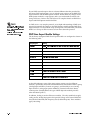
When displaying numeric values, the MGT can display up to four digits of
resolution. If more than four digits of resolution are required, use PEGASYS
software to display data. If a value is too large or too small to be displayed with
four digits, the MGT uses an abbreviated engineering notation that uses
standard metric prefixes to indicate the magnitude of the reading. For example,
MGT Display
Value
12m40....................................... 0.0124
12K40 ....................................... 12, 400
12M40 ...................................... 12, 400, 000
1G240 ....................................... 1, 240, 000, 000
Numeric values are displayed in base units; voltages are displayed in volts,
while current is displayed in amps. The following values, however, are
displayed in kilo units rather than base units since kilo is the most frequently
used measurement:
♦
kW
♦
kVA
♦
kVAR
When viewing these parameters with the MGT, remember that the values are
already multiplied by 1000. For example, the reading below indicates 120, 000
kilowatts, not 120, 000 watts.
kW total ..................................120K0
-2:0(ERH2%1IWWEKIW
If the MGT is unable to read a numeric or status value from the 7700 ION, it will
display either INVLD or N/A in place of the value. INVLD indicates that the value
received cannot be displayed because it is either too large or too small (it is
below 1m000 or above 9G999). N/A appears if the register is not available.
-3297)6
7+9-()
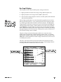
&EV+VETL(MWTPE]W
Three display screens are provided for phase voltage and current:
238)
(DFK
RI
WKH
0*7
GLVSOD\
VFUHHQV FDQ EH DGMXVWHG WR
PDWFK
5HIHU
\RXU
WR
SRZHU
V\VWHP
´&UHDWLQJ
&XVWRP
0*7'LVSOD\VµLQ&KDSWHU
♦
High-speed line-to-neutral and average voltage (100 ms update rate)
♦
High-speed phase and average current (100 ms update rate)
♦
Line-to-neutral voltage and phase current (1 second update) with minimum
and maximum indicators.
The two high-speed displays use a four-channel bar graph that shows the low
limit, the parameter name (i.e. Vln a, meaning line-to-neutral voltage on phase
A), and the upper limit above the bar for each measurement. The high-speed
voltage display, called VOLTAGE HS BAR GRAPH, has fixed limits of 0 to 400 volts.
The high-speed current display, called CURRENT HS BAR GRAPH, has fixed limits
of 0 to 6000 Amps. If your voltage or current values are above the fixed upper
limits, the MGT will display OFF SCALE in place of the bar. Similarly, the voltage
bar graph displays OFF SCALE if you have a Delta power system, as there are no
line-to-neutral voltage values available.
The phase voltage and current bar graph, called VOLTS/AMPS BAR GRAPH,
displays line-to-neutral phase voltage and phase current values. As with the
high-speed bar graphs, voltage limits of 0 to 400 Volts and current limits of 0 to
6000 Amps are fixed, and line-to-neutral voltages will read OFF SCALE if viewed
in a Delta power system.
The VOLTS/AMPS BAR GRAPH also shows the minimum and maximum values
measured (since power-up or the last min/max reset). Small triangles located
on each parameter’s bar indicate the min/max values:
7KH PD[LPXP YDOXH LV
7KH PLQLPXP YDOXH LV
LQGLFDWHGE\WKLVWULDQJOH
LQGLFDWHGE\WKLVWULDQJOH
(-740%=-2+(%8%
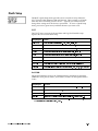
8VIRH(MWTPE]W
Trend display screens are provided for total kW and total kVAR. Both screens
show the values for each parameter over the last 150 seconds.
The limits set for total kW and total kVAR are 0 to 2400. If the total kW or total
kVAR in your system are above this range, no trend graph will be displayed.
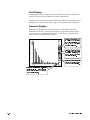
,EVQSRMGW(MWTPE]W
Harmonics are displayed for each current phase. All harmonics from the
rd
fundamental to the 63 can be displayed at once, or harmonics can be shown
across two screens. The Harmonics display screens can be adjusted to show
even harmonics, odd harmonics, or both.
3UHVVWKHEXWWRQQH[WWR 2''
WR GLVSOD\ RGG KDUPRQLFV
2'' ZLOO EH KLJKOLJKWHG DV
VKRZQ LI RGG KDUPRQLFV
DUHEHLQJGLVSOD\HG
3UHVV WKH EXWWRQ QH[W WR (9(
WR GLVSOD\ HYHQ KDUPRQLFV
(9( ZLOO EH KLJKOLJKWHG DV
VKRZQ LI HYHQ KDUPRQLFV
DUHEHLQJGLVSOD\HG
3UHVV WKH EXWWRQ QH[W WR WKLV
JUDSKLF WR WRJJOH EHWZHHQ
RQHRUWZRVFUHHQGLVSOD\V
7KLV DUURZ DSSHDUV LI WKH WZRVFUHHQ
GLVSOD\ LV VHOHFWHG 3UHVV WKH EXWWRQ
QH[W WR WKLV DUURZ WR PRYH EHWZHHQ
WKHWZRGLVSOD\VFUHHQV
-3297)6
7+9-()
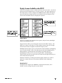
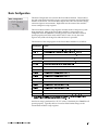
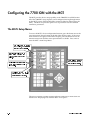
(MWTPE]7GVIIRW%ZEMPEFPIYRHIV7)894
There are five display screens available under the SETUP menu item. You do not
require password authorization to view these screens. The other eight items in
the setup menu are used to configure the 7700 ION and the MGT, and require
password authority (setup functions are described in the next chapter). Press
SETUP on the main MGT screen to display these options:
7KH
WKUHH
1$0(3/$7(
,1)2
VFUHHQV GLVSOD\ LQIRUPDWLRQ
DERXW WKH ,21 DQG LWV
VHWWLQJV
(QWHU
',63/$<
237,216
WR
&KRRVH
'$7(7,0(
',63/$<
WR
DGMXVWWKH0*7·V FRQWUDVW
KDYH WKH 0*7 GLVSOD\ GDWH
QXPEHU
WLPHDQGWLPH]RQH
GLVSOD\
IRUPDW
DQGEDFNOLJKWWLPHRXW
(MWTPE]3TXMSRW
The DISPLAY OPTIONS menu includes three options: Adjust Contrast, Backlight
Timeout and Numbers X.XXX.
Adjust Contrast allows you to change the contrast of the MGT’s display. The
MGT has a contrast scale of 0 to 15. Select Adjust Contrast, then use the right
and left arrow buttons to lighten or darken the display screen.
Backlight Timeout allows you to set the amount of time the MGT’s backlighting
stays on when the MGT is idle. The bulb that provides the backlighting has a
limited lifespan; to prolong the life of the bulb, you should only have
backlighting on when you are actively using the MGT. Select Backlight
Timeout, then enter the amount of time in seconds that the light should stay on
after a button has been pressed.
Numbers X.XXX lets you change the numeric display format to use either a
period or a comma character as the decimal delimiter when displaying
numbers.
2EQITPEXI-RJS
Nameplate Info 1 displays the 7700 ION’s manufactured location, serial
number, accuracy rating, and power system details.
(-740%=-2+(%8%
2EQITPEXI-RJS
238)
$GGLWLRQDO LQIRUPDWLRQ ZLOO EH
GLVSOD\HG LQ WKH 1DPHSODWH
,QIRVFUHHQVLIWKH0*7LVXVHG
ZLWK UHYHQXHFODVV ,21
PHWHUV
Nameplate Info 2 displays the MGT’s acceptable operating temperature, the
amount of battery life left in the 7700 ION, and the configured demand settings.
2EQITPEXI-RJS
Nameplate Info 3 displays the three lines of text that are written into the 7700
ION’s Factory module. You can customize the text displayed by configuring
the Factory module’s Owner, Tag1 and Tag2 setup registers in ION Designer.
Nameplate Info 3 also shows the firmware revisions of the 7700 ION, the MGT
and the XPRESS CARD (if one exists), as well as the optional auxiliary I/O board’s
voltage level and the total amount of memory in the 7700 ION.
(EXI8MQI(MWTPE]
The MGT can be set to display the date, time and timezone. To display the data
and time, press SETUP, then press DATE/TIME DISPLAY. You can exit the
date/time screen at any time by holding the ESC button down for two seconds.
-3297)6
7+9-()
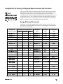
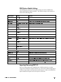
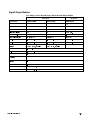
'SQTPIXI0MWXSJ*EGXSV]'SRJMKYVIH1IEWYVIQIRXWERH*YRGXMSRW
The standard PEGASYS Vista diagrams, the PowerView Data Screens and the
MGT display screens show much of the data that the factory-configured 7700
ION measures and calculates. There is additional data, however, that is
available from the factory-configured meter but not presented by default in any
of these display tools. This section lists all of the data provided by the factoryconfigured meter, and shows which parameters are displayed or accessible by
default in each of the tools provided by Power Measurement.
238)
7KH ,21 PRGXOHV DQG RXWSXW
UHJLVWHUV XVHG IRU HDFK IXQFWLRQ
DUHOLVWHGLQWKLVVHFWLRQWR DVVLVW
PRUH DGYDQFHG XVHUV 7\SLFDO
XVHUVFDQLJQRUHWKHWKUHHULJKW
KDQG FROXPQV LQ WKH WDEOHV
EHORZ
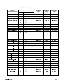
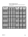
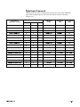
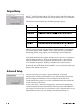
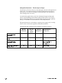
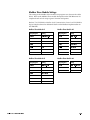
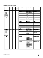
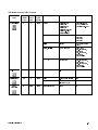
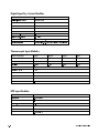
)RIVK](IQERH*VEQI[SVO
The energy and demand configuration calculates and logs energy values and
both Thermal and Sliding Window demand. External triggers are included for
operator reset of all values.
(IWGVMTXMSRSJ
4EVEQIXIVSV*YRGXMSR
(MWTPE]IH%GGIWWMFPIF](IJEYPX
-321SHYPI
2EQI
-321SHYPI
0EFIP
3YXTYX6IKMWXIV
0EFIP
:MWXE
4S[IV:MI[
1+8
,PSRUWHGN:K
l
l
l
,QWHJUDWRU
N:KLPS
N:KLPS
([SRUWHGN:K
l
l
l
,QWHJUDWRU
N:KH[S
N:KH[S
l
l
,QWHJUDWRU
N:KWRW
N:KWRW
l
,QWHJUDWRU
N:KQHW
N:KQHW
7RWDON:K
1HWN:K
l
,PSRUWHGN9$5K
l
l
l
,QWHJUDWRU
N9$5KLPS
N9$5KLPS
([SRUWHGN9$5K
l
l
l
,QWHJUDWRU
N9$5KH[S
N9$5KH[S
l
l
,QWHJUDWRU
N9$5KWRW
N9$5KWRW
l
,QWHJUDWRU
N9$5KQHW
N9$5KQHW
l
l
,QWHJUDWRU
N9$K
N9$K
N:WKHUPDOGHPDQG7'
l
l
7KHUPDO'HPDQG
N:WG
N:WG
N9$57'
l
l
7KHUPDO'HPDQG
N9$5WG
N9$5WG
N9$7'
l
l
7KHUPDO'HPDQG
N9$WG
N9$WG
$YHUDJHFXUUHQW7'
l
l
7KHUPDO'HPDQG
,DYJWG
,DYJWG
3HULRGLF7LPHU
(J\'PG/RJ7UJ
(J\'PG/RJ7UJ
l
([WHUQDO%RROHDQ
(J\'PG/RJ(QEO
(J\'PG/RJ(QEO
l
([WHUQDO%RROHDQ
(QHUJ\(QEOH
(QHUJ\(QEOH
7RWDON9$5K
1HWN9$5K
l
N9$K
l
(QHUJ\'HPDQG
/RJJLQJWULJJHU
(QHUJ\'HPDQG
l
5HFRUGHU(QDEOH
(QHUJ\&DOF(QDEOH
N:6:'HPDQG
l
N:3UHGLFWHG'HPDQG
N9$56:'HPDQG
l
N9$53UHGLFWHG'HPDQG
N9$6:'HPDQG
6:'HPDQG
(-740%=-2+(%8%
l
l
l
6:'HPDQG
N:VZG
N:VZG
l
l
6:'HPDQG
N:VZG
N:SUHGVZG
l
l
6:'HPDQG
N9$5VZG
N9$5VZG
l
l
6:'HPDQG
N9$5VZG
N9$5SUHGVZG
l
l
6:'HPDQG
N9$VZG
N9$VZG
6OLGLQJ:LQGRZ'HPDQG
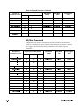
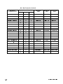
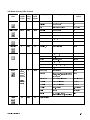
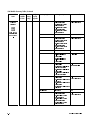
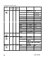
)RIVK]ERH(IQERH*VEQI[SVO'SRXMRYIH
(IWGVMTXMSRSJ
4EVEQIXIVSV*YRGXMSR
(MWTPE]IH%GGIWWMFPIF](IJEYPX
:MWXE
-321SHYPI
2EQI
-321SHYPI
0EFIP
3YXTYX6IKMWXIV
0EFIP
4S[IV:MI[
1+8
N9$3UHGLFWHG'HPDQG
l
l
6:'HPDQG
N9$VZG
N9$SUHGVZG
$YJ&XUUHQW6:'HPDQG
l
l
6:'HPDQG
,DYJVZG
,DYJVZG
$YJ&XUUHQW6:'HPDQG
l
l
6:'HPDQG
,DYJVZG
,DYJSUHGVZG
(QHUJ\UHVHWWULJJHU
l
l
([WHUQDO3XOVH
(QHUJ\5VHW
(QHUJ\5VHW
6:'UHVHWWULJJHU
l
l
([WHUQDO3XOVH
6:'HPDQG5VHW
6:'HPDQG5VHW
7'UHVHWWULJJHU
l
([WHUQDO3XOVH
7GHPDQG5VHW
7GHPDQG5VHW
(QHUJ\'HPDQG
l
'DWD5HFRUGHU
(J\'PG/RJ
(J\'PG/RJ
5HFRUGHU
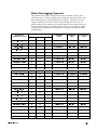
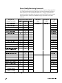
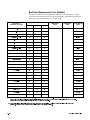
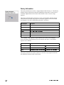
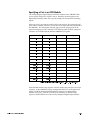
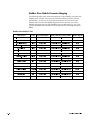
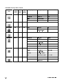
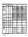
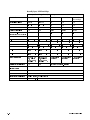
1MR1E\*VEQI[SVO
This portion of the meter’s configuration measures minimum and maximum
values for various power, energy, demand and harmonics parameters. Separate
reset triggers are provided for demand, harmonics and ‘standard’ power
parameters.
(IWGVMTXMSRSJ
4EVEQIXIVSV*YRGXMSR
(MWTPE]IH%GGIWWMFPIF](IJEYPX
-321SHYPI
0EFIP
3YXTYX6IKMWXIV
0EFIP
:MWXE
4S[IV:MI[
1+8
0D[3KDVH$/19ROWV
l
l
l
0D[LPXP
9OQDP[
9OQDP[
0D[3KDVH%/19ROWV
l
l
l
0D[LPXP
9OQEP[
9OQEP[
0D[3KDVH&/19ROWV
l
l
l
0D[LPXP
9OQFP[
9OQFP[
l
l
0D[LPXP
9OQDYJP[
9OQDYJP[
0D[$YHUDJH/19ROWV
0D[//9ROWV$%
l
l
l
0D[LPXP
9OODEP[
9OODEP[
0D[//9ROWV%&
l
l
l
0D[LPXP
9OOEFP[
9OOEFP[
0D[//9ROWV&$
l
l
l
0D[LPXP
9OOFDP[
9OOFDP[
l
l
0D[LPXP
9OODYJP[
9OODYJP[
0D[$YHUDJH//9ROWV
0D[9ROWDJH8QEDODQFH
l
l
l
0D[LPXP
9XQEDOP[
9XQEDOP[
0D[3KDVH$&XUUHQW
l
l
l
0D[LPXP
,DP[
,DP[
0D[3KDVH%&XUUHQW
l
l
l
0D[LPXP
,EP[
,EP[
0D[3KDVH&&XUUHQW
l
l
l
0D[LPXP
,FP[
,FP[
l
l
0D[LPXP
,DYJP[
,DYJP[
0D[$YHUDJH&XUUHQW
-321SHYPI
2EQI
0D[N:WRWDO
l
l
l
0D[LPXP
N:WRWP[
N:WRWP[
0D[N9$5WRWDO
l
l
l
0D[LPXP
N9$5WRWP[
N9$5WRWP[
-3297)6
7+9-()
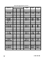
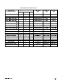
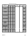
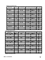
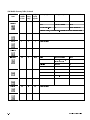
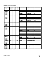
1MR1E\*VEQI[SVO'SRXMRYIH
(IWGVMTXMSRSJ
4EVEQIXIVSV*YRGXMSR
(MWTPE]IH%GGIWWMFPIF](IJEYPX
-321SHYPI
0EFIP
3YXTYX6IKMWXIV
0EFIP
0D[LPXP
N9$WRWP[
N9$WRWP[
:MWXE
4S[IV:MI[
0D[N9$WRWDO
l
l
0D[3KDVH$&XUUHQW7+'
l
l
l
0D[LPXP
,7+'P[
,7+'P[
0D[3KDVH%&XUUHQW7+'
l
l
l
0D[LPXP
,7+'P[
,7+'P[
0D[3KDVH&&XUUHQW7+'
l
l
l
0D[LPXP
,7+'P[
,7+'P[
0D[)UHTXHQF\
l
l
0D[LPXP
)UHTP[
)UHTP[
l
0D[LPXP
3)OHDGP[
3)OHDGP[
0D[LPXP
3)ODJP[
3)ODJP[
0D[3RZHU)DFWRU/HDG
1+8
-321SHYPI
2EQI
0D[3RZHU)DFWRU/DJ
l
l
0D[3KDVH$9ROWDJH7+'
l
l
l
0D[LPXP
97+'P[
97+'P[
0D[3KDVH%9ROWDJH7+'
l
l
l
0D[LPXP
97+'P[
97+'P[
0D[3KDVH&9ROWDJH7+'
l
l
l
0D[LPXP
97+'P[
97+'P[
0D[N:6:'HPDQG
l
l
l
0D[LPXP
N:VZGP[
N:VZGP[
0D[N9$56:'HPDQG
l
l
l
0D[LPXP
N9$5VZGP[
N9$5VZGP[
0D[N9$6:'HPDQG
l
l
l
0D[LPXP
N9$VZGP[
N9$VZGP[
0D[N:7KHUPDO'HPDQG
l
l
0D[LPXP
N:WGP[
N:WGP[
0D[N9$57KHUP'HPDQG
l
l
0D[LPXP
N9$5WGP[
N9$5WGP[
0D[N9$7KHUPDO'HPDQG
l
l
0D[LPXP
N9$WGP[
N9$WGP[
0LQ3KDVH$/19ROWV
l
l
l
0LQLPXP
9OQDPQ
9OQDPQ
0LQ3KDVH%/19ROWV
l
l
l
0LQLPXP
9OQEPQ
9OQEPQ
0LQ3KDVH&/19ROWV
l
l
l
0LQLPXP
9OQFPQ
9OQFPQ
l
l
0LQLPXP
9OQDYJPQ
9OQDYJPQ
0LQ$YHUDJH/19ROWV
0LQ//9ROWV$%
l
l
l
0LQLPXP
9OODEPQ
9OODEPQ
0LQ//9ROWV%&
l
l
l
0LQLPXP
9OOEFPQ
9OOEFPQ
0LQ//9ROWV&$
l
l
l
0LQLPXP
9OOFDPQ
9OOFDPQ
l
l
0LQLPXP
9OODYJPQ
9OODYJPQ
0LQ$YHUDJH//9ROWV
0LQ9ROWDJH8QEDODQFH
l
l
l
0LQLPXP
9XQEDOPQ
9XQEDOPQ
0LQ3KDVH$&XUUHQW
l
l
l
0LQLPXP
,DPQ
,DPQ
0LQ3KDVH%&XUUHQW
l
l
l
0LQLPXP
,EPQ
,EPQ
0LQ3KDVH&&XUUHQW
l
l
l
0LQLPXP
,FPQ
,FPQ
l
l
0LQLPXP
,DYJPQ
,DYJPQ
0LQ$YHUDJH&XUUHQW
0LQN:WRWDO
l
l
l
0LQLPXP
N:WRWPQ
N:WRWPQ
0LQN9$5WRWDO
l
l
l
0LQLPXP
N9$5WRWPQ
N9$5WRWPQ
(-740%=-2+(%8%
1MR1E\*VEQI[SVO'SRXMRYIH
(IWGVMTXMSRSJ
4EVEQIXIVSV*YRGXMSR
(MWTPE]IH%GGIWWMFPIF](IJEYPX
-321SHYPI
0EFIP
3YXTYX6IKMWXIV
0EFIP
0LQLPXP
N9$WRWPQ
N9$WRWPQ
:MWXE
4S[IV:MI[
0LQN9$WRWDO
l
l
0LQ3KDVH$&XUUHQW7+'
l
l
l
0LQLPXP
,7+'PQ
,7+'PQ
0LQ3KDVH%&XUUHQW7+'
l
l
l
0LQLPXP
,7+'PQ
,7+'PQ
0LQ3KDVH&&XUUHQW7+'
l
l
l
0LQLPXP
,7+'PQ
,7+'PQ
0LQ)UHTXHQF\
l
l
0LQLPXP
)UHTPQ
)UHTPQ
l
0LQLPXP
3)OHDGPQ
3)OHDGPQ
0LQLPXP
3)ODJPQ
3)ODJPQ
0LQ3RZHU)DFWRU/HDG
1+8
-321SHYPI
2EQI
0LQ3RZHU)DFWRU/DJ
l
l
0LQ3KDVH$9ROWDJH7+'
l
l
l
0LQLPXP
97+'PQ
97+'PQ
0LQ3KDVH%9ROWDJH7+'
l
l
l
0LQLPXP
97+'PQ
97+'PQ
0LQ3KDVH&9ROWDJH7+'
l
l
l
0LQLPXP
97+'PQ
97+'PQ
0LQN:6:'HPDQG
l
l
0LQLPXP
N:VZGPQ
N:VZGPQ
0LQN9$56:'HPDQG
l
l
0LQLPXP
N9$5VZGPQ
N9$5VZGPQ
0LQ3KDVH&&XUUHQW7+'
l
l
0LQLPXP
N9$WGPQ
N9$WGPQ
0LQN:7KHUPDO'HPDQG
l
l
0LQLPXP
N:WGPQ
N:WGPQ
0LQN9$57KHUP'HPDQG
l
l
0LQLPXP
N9$5WGPQ
N9$5WGPQ
0LQN9$7KHUPDO'HPDQG
l
l
0LQLPXP
N9$WGPQ
N9$WGPQ
0LQ0D[(QDEOH
l
([WHUQDO%RROHDQ
0Q0[(QEOH
0Q0[(QEOH
9$3RZHU0LQ0D[5HVHW
l
l
([WHUQDO3XOVH
0Q0[5VHW
0Q0[5VHW
'HPDQG0LQ0D[5HVHW
l
l
([WHUQDO3XOVH
3HDN'PG5VHW
3HDN'PG5VHW
+DUPRQLFVPLQPD[5HVHW
l
l
([WHUQDO3XOVH
+DUP0Q0[5VHW
+DUP0Q0[5VHW
-3297)6
7+9-()
,MWXSVMG(EXE0SKKMRK*VEQI[SVO
This portion of the meter’s configuration records ‘standard’ power system
parameters such as voltage, current, power, frequency and power factor. Low,
mean and high values are recorded for all parameters. Note that ‘low’ and
‘high’ are different from ‘min’ and ‘max’: low and high are reset every 15
minutes, whereas min and max are typically long-term measurements that are
only reset by the operator. Similarly, ‘mean’ is reset every 15 minutes, unlike
‘average’ which is typically an instantaneous averaging of multiple real-time
measurements.
(IWGVMTXMSRSJ
4EVEQIXIVSV*YRGXMSR
(MWTPE]IH%GGIWWMFPIF](IJEYPX
-321SHYPI
0EFIP
3YXTYX6IKMWXIV
0EFIP
:MWXE
4S[IV:MI[
0HDQ//9ROWV$%
l
l
6:'HPDQG
9OODEPHDQ
9OODEPHDQ
0HDQ//9ROWV%&
l
l
6:'HPDQG
9OOEFPHDQ
9OOEFPHDQ
0HDQ//9ROWV&$
l
l
6:'HPDQG
9OOFDPHDQ
9OOFDPHDQ
0HDQ//9ROWVDYHUDJH
l
l
6:'HPDQG
9OODYJPHDQ
9OODYJPHDQ
0HDQ9ROWDJH8QEDODQFH
l
l
6:'HPDQG
9XQEDOPHDQ
9XQEDOPHDQ
0HDQ3KDVH$&XUUHQW
l
l
6:'HPDQG
,DPHDQ
,DPHDQ
0HDQ3KDVH%&XUUHQW
l
l
6:'HPDQG
,EPHDQ
,EPHDQ
0HDQ3KDVH&&XUUHQW
l
l
6:'HPDQG
,FPHDQ
,FPHDQ
0HDQ$YHUDJH&XUUHQW
l
l
6:'HPDQG
,DYJPHDQ
,DYJPHDQ
0HDQ1HXWUDO&XUUHQW
l
l
6:'HPDQG
,PHDQ
,PHDQ
0HDQN:WRWDO
l
l
6:'HPDQG
N:WRWPHDQ
N:WRWPHDQ
0HDQN9$5WRWDO
l
l
6:'HPDQG
N9$5WRWPHDQ
N9$5WRWPHDQ
0HDQN9$WRWDO
l
l
6:'HPDQG
N9$WRWPHDQ
N9$WRWPHDQ
0HDQ3RZHU)DFWRUODJ
l
l
6:'HPDQG
3)ODJPHDQ
3)ODJPHDQ
0HDQ3RZHU)DFWRUOHDG
l
l
6:'HPDQG
3)OHDGPHDQ
3)OHDGPHDQ
0HDQ)UHTXHQF\
l
l
6:'HPDQG
)UHTPHDQ
)UHTPHDQ
+LJK//9ROWV$%
l
l
0D[LPXP
9OODEKLJK
9OODEKLJK
+LJK//9ROWV%&
l
l
0D[LPXP
9OOEFKLJK
9OOEFKLJK
+LJK//9ROWV&$
l
l
0D[LPXP
9OOFDKLJK
9OOFDKLJK
+LJK//9ROWVDYHUDJH
l
l
0D[LPXP
9OODYJKLJK
9OODYJKLJK
+LJK9ROWDJH8QEDODQFH
l
l
0D[LPXP
9XQEDOKLJK
9XQEDOKLJK
+LJK3KDVH$&XUUHQW
l
l
0D[LPXP
,DKLJK
,DKLJK
+LJK3KDVH%&XUUHQW
l
l
0D[LPXP
,EKLJK
,EKLJK
+LJK3KDVH&&XUUHQW
l
l
0D[LPXP
,FKLJK
,FKLJK
+LJK$YHUDJH&XUUHQW
l
l
0D[LPXP
,DYJKLJK
,DYJKLJK
+LJK1HXWUDO&XUUHQW
l
l
0D[LPXP
,KLJK
,KLJK
(-740%=-2+(%8%
1+8
-321SHYPI
2EQI
,MWXSVMG(EXE0SKKMRK*VEQI[SVO'SRXMRYIH
(IWGVMTXMSRSJ
4EVEQIXIVSV*YRGXMSR
(MWTPE]IH%GGIWWMFPIF](IJEYPX
3YXTYX6IKMWXIV
0EFIP
4S[IV:MI[
+LJKN:WRWDO
l
l
0D[LPXP
N:WRWKLJK
N:WRWKLJK
+LJKN9$5WRWDO
l
l
0D[LPXP
N9$5WRWKLJK
N9$5WRWKLJK
+LJKN9$WRWDO
l
l
0D[LPXP
N9$WRWKLJK
N9$WRWKLJK
+LJK3RZHU)DFWRUODJ
l
l
0D[LPXP
3)ODJKLJK
3)ODJKLJK
+LJK3RZHU)DFWRUOHDG
l
l
0D[LPXP
3)OHDGKLJK
3)OHDGKLJK
+LJK)UHTXHQF\
l
l
0D[LPXP
)UHTKLJK
)UHTKLJK
/RZ//9ROWV$%
l
l
0LQLPXP
9OODEORZ
9OODEORZ
/RZ//9ROWV%&
l
l
0LQLPXP
9OOEFORZ
9OOEFORZ
/RZ//9ROWV&$
l
l
0LQLPXP
9OOFDORZ
9OOFDORZ
/RZ//9ROWVDYHUDJH
l
l
0LQLPXP
9OODYJORZ
9OODYJORZ
/RZ9ROWDJH8QEDODQFH
l
l
0LQLPXP
9XQEDOORZ
9XQEDOORZ
/RZ3KDVH$&XUUHQW
l
l
0LQLPXP
,DORZ
,DORZ
/RZ3KDVH%&XUUHQW
l
l
0LQLPXP
,EORZ
,EORZ
/RZ3KDVH&&XUUHQW
l
l
0LQLPXP
,FORZ
,FORZ
/RZ$YHUDJH&XUUHQW
l
l
0LQLPXP
,DYJORZ
,DYJORZ
/RZ1HXWUDO&XUUHQW
l
l
0LQLPXP
,ORZ
,ORZ
/RZN:WRWDO
l
l
0LQLPXP
N:WRWORZ
N:WRWORZ
/RZN9$5WRWDO
l
l
0LQLPXP
N9$5WRWORZ
N9$5WRWORZ
/RZN9$WRWDO
l
l
0LQLPXP
N9$WRWORZ
N9$WRWORZ
/RZ3RZHU)DFWRUODJ
l
l
0LQLPXP
3)ODJORZ
3)ODJORZ
/RZ3RZHU)DFWRUOHDG
l
l
0LQLPXP
3)OHDGORZ
3)OHDGORZ
/RZ)UHTXHQF\
l
l
0LQLPXP
)UHTORZ
)UHTORZ
l
3HULRGLF7LPHU
+LVW/RJ7UJ
+LVW/RJ7UJ
l
([WHUQDO%RROHDQ
+LVW/RJ(QEOH
+LVW/RJ(QEOH
+LJKYDOXH5HVHW
l
)HHGEDFN
5HVHW+LVWKLJK
5HVHW+LVWKLJK
/RZYDOXH5HVHW
l
)HHGEDFN
5HVHW+LVWORZ
5HVHW+LVWORZ
0HDQYDOXHUHFRUGHU
l
'DWD5HFRUGHU
+LVWPHDQ/RJ
+LVWPHDQ/RJ
+LJKYDOXHUHFRUGHU
l
'DWD5HFRUGHU
+LVWKLJK/RJ
+LVWKLJK/RJ
/RZYDOXHUHFRUGHU
l
'DWD5HFRUGHU
+LVWORZ/RJ
+LVWORZ/RJ
+LVWRULF/RJJLQJ(QDEOH
-321SHYPI
0EFIP
:MWXE
+LVWRULF/RJJLQJ7ULJJHU
l
1+8
-321SHYPI
2EQI
-3297)6
7+9-()
,EVQSRMGW0SKKMRK*VEQI[SVO
This portion of the factory configuration records voltage and current harmonics
measurements. Mean and average values are calculated, recorded and then
reset every 60 minutes.
(IWGVMTXMSRSJ
4EVEQIXIVSV*YRGXMSR
(MWTPE]IH%GGIWWMFPIF](IJEYPX
-321SHYPI
0EFIP
3YXTYX6IKMWXIV
0EFIP
:MWXE
4S[IV:MI[
0HDQ3KDVH$9ROWDJH7+'
l
l
6:'HPDQG
97+'PHDQ
97+'PHDQ
0HDQ3KDVH%9ROWDJH7+'
l
l
6:'HPDQG
97+'PHDQ
97+'PHDQ
0HDQ3KDVH&9ROWDJH7+'
l
l
6:'HPDQG
97+'PHDQ
97+'PHDQ
0HDQ3KDVH$&XUUHQW7+'
l
l
6:'HPDQG
,7+'PHDQ
,7+'PHDQ
0HDQ3KDVH%&XUUHQW7+'
l
l
6:'HPDQG
,7+'PHDQ
,7+'PHDQ
0HDQ3KDVH&&XUUHQW7+'
l
l
6:'HPDQG
,7+'PHDQ
,7+'PHDQ
0HDQ3KDVH$&XUUHQW.)DFWRU
l
l
6:'HPDQG
,.)DFPHDQ
,.)DFPHDQ
0HDQ3KDVH%&XUUHQW.)DFWRU
l
l
6:'HPDQG
,.)DFPHDQ
,.)DFPHDQ
0HDQ3KDVH&&XUUHQW.)DFWRU
l
l
6:'HPDQG
,.)DFPHDQ
,.)DFPHDQ
+LJK3KDVH$9ROWDJH7+'
l
l
0D[LPXP
97+'KLJK
97+'KLJK
+LJK3KDVH%9ROWDJH7+'
l
l
0D[LPXP
97+'KLJK
97+'KLJK
+LJK3KDVH&9ROWDJH7+'
l
l
0D[LPXP
97+'KLJK
97+'KLJK
+LJK3KDVH$&XUUHQW7+'
l
l
0D[LPXP
,7+'KLJK
,7+'KLJK
+LJK3KDVH%&XUUHQW7+'
l
l
0D[LPXP
,7+'KLJK
,7+'KLJK
+LJK3KDVH&&XUUHQW7+'
l
l
0D[LPXP
,7+'KLJK
,7+'KLJK
+LJK3KDVH$&XUUHQW.)DFWRU
l
l
l
0D[LPXP
,.)DFKLJK
,.)DFKLJK
+LJK3KDVH%&XUUHQW.)DFWRU
l
l
l
0D[LPXP
,.)DFKLJK
,.)DFKLJK
+LJK3KDVH&&XUUHQW.)DFWRU
l
l
l
0D[LPXP
,.)DFKLJK
,.)DFKLJK
l
3HULRGLF7LPHU
+DUP/RJ7UJ
+DUP/RJ7UJ
l
([WHUQDO%RROHDQ
+DUP/RJ(QEOH
+DUP/RJ(QEOH
+LJK+DUPRQLFVUHVHW
l
)HHGEDFN
5VHW+DUPKLJK
5VHW+DUPKLJK
0HDQ+DUPRQLFV5HFRUGHU
l
'DWD5HFRUGHU
+DUPPHDQ/RJ
+DUPPHDQ/RJ
+LJK+DUPRQLFV5HFRUGHU
l
'DWD5HFRUGHU
+DUPKLJK/RJ
+DUPKLJK/RJ
+DUPRQLFV/RJJLQJWULJJHU
+DUPRQLFV/RJJLQJHQDEOH
7+'
l
1+8
-321SHYPI
2EQI
7RWDO+DUPRQLF'LVWRUWLRQ
(-740%=-2+(%8%
4S[IV5YEPMX]1SRMXSVMRK*VEQI[SVO
This portion of the factory configuration monitors the phase voltage signals for
sag/swell and transient events, and triggers waveform recordings when they
occur (statistics are also recorded for each event). A trigger is provided for
manual waveform recording, and counters are included to display the number
of events that have occurred (an additional trigger provided to reset these
counters).
(IWGVMTXMSRSJ
4EVEQIXIVSV*YRGXMSR
(MWTPE]IH%GGIWWMFPIF](IJEYPX
1+8
-321SHYPI
2EQI
-321SHYPI
0EFIP
3YXTYX6IKMWXIV
0EFIP
6DJ6ZHOO
6DJ6ZHOO
66'LVW'XU
:MWXE
4S[IV:MI[
6DJRU6ZHOO'XUDWLRQ
l
l
3KDVH$PLQ9ROWDJH
l
l
66'LVW90LQ
3KDVH$PD[9ROWDJH
l
l
66'LVW90D[
3KDVH$DYHUDJH9ROWDJH
l
66'LVW9$YJ
3KDVH$(QHUJ\YDULDQFH
l
66'LVW9(QJ\
3KDVH%PLQ9ROWDJH
l
l
66'LVW90LQ
3KDVH%PD[9ROWDJH
l
l
66'LVW90D[
3KDVH%DYHUDJH9ROWDJH
l
66'LVW9$YJ
3KDVH%(QHUJ\YDULDQFH
l
66'LVW9(QJ\
3KDVH&PLQ9ROWDJH
l
l
66'LVW90LQ
3KDVH&PD[9ROWDJH
l
l
66'LVW90D[
3KDVH&DYHUDJH9ROWDJH
l
66'LVW9$YJ
3KDVH&(QHUJ\YDULDQFH
l
66'LVW9(QJ\
1RPLQDO9ROWDJHDWWKHEHJLQQLQJ
l
66'LVW1RPLQDO
9ROWDJHOHYHOFRQVLGHUHGD6ZHOO
l
666ZHOO/LP
9ROWDJHOHYHOFRQVLGHUHGD6DJ
l
666DJ/LP
RI6DJRU6ZHOOGLVWXUEDQFH
3KDVH$7UDQVLHQWGXUDWLRQ
l
l
3KDVH$0D[3HDN7UDQVLHQW
l
l
757UDQ90D[
3KDVH%7UDQVLHQWGXUDWLRQ
l
l
757UDQ9'XU
3KDVH%0D[3HDN7UDQVLHQW
l
l
757UDQ90D[
3KDVH&7UDQVLHQWGXUDWLRQ
l
l
757UDQ9'XU
3KDVH&0D[3HDN7UDQVLHQW
l
l
757UDQ90D[
l
757UDQ1RPLQDO
l
757KUHVKROG
1RPLQDO9ROWDJHDWWKHEHJLQQLQJ
7UDQVLHQW
7UDQVLHQW
757UDQ9'XU
RI7UDQVLHQWGLVWXUEDQFH
9ROWDJHIOXFWXDWLRQDPRXQW
FRQVLGHUHGD7UDQVLHQW
7KHVHDUHVHWXSUHJLVWHUVQRWRXWSXWUHJLVWHUV
-3297)6
7+9-()
4S[IV5YEPMX]*VEQI[SVO'SRXMRYIH
(IWGVMTXMSRSJ
4EVEQIXIVSV*YRGXMSR
(MWTPE]IH%GGIWWMFPIF](IJEYPX
:MWXE
4S[IV:MI[
1+8
-321SHYPI
2EQI
-321SHYPI
0EFIP
3YXTYX6IKMWXIV
0EFIP
6DJ6ZHOO'DWD5HFRUGHU
l
'DWD5HFRUGHU
6DJ6ZHOO/RJ
6DJ6ZHOO/RJ
7UDQVLHQW'DWD5HFRUGHU
l
'DWD5HFRUGHU
7UDQVLHQW/RJ
7UDQVLHQW/RJ
3KDVH$9ROWDJH:DYHIRUP5HF
l
:DYHIRUP5HFRUGHU
:IP5HF9
:IP5HF9
3KDVH%9ROWDJH:DYHIRUP5HF
l
:DYHIRUP5HFRUGHU
:IP5HF9
:IP5HF9
3KDVH&9ROWDJH:DYHIRUP5HF
l
:DYHIRUP5HFRUGHU
:IP5HF9
:IP5HF9
3KDVH$&XUUHQW:DYHIRUP5HF
l
l
:DYHIRUP5HFRUGHU
:IP5HF,
:IP5HF,
3KDVH%&XUUHQW:DYHIRUP5HF
l
l
:DYHIRUP5HFRUGHU
:IP5HF,
:IP5HF,
3KDVH&&XUUHQW:DYHIRUP5HF
l
l
:DYHIRUP5HFRUGHU
:IP5HF,
:IP5HF,
6DJ6ZHOOPRQLWRULQJ(QDEOH
l
l
([WHUQDO%RROHDQ
6DJ6ZHOO(QEOH
6DJ6ZHOO(QEOH
7UDQVLHQWPRQLWRULQJ(QDEOH
l
l
([WHUQDO%RROHDQ
7UDQVLHQW(QEOH
7UDQVLHQW(QEOH
:DYHIRUP5HFRUGLQJ(QDEOH
l
l
([WHUQDO%RROHDQ
:IP5HF(QEOH
:IP5HF(QEOH
'LVWXUEDQFH&RXQWHUUHVHW
l
l
([WHUQDO3XOVH
'LVW&RXQW5VHW
'LVW&RXQW5VHW
0DQXDO:DYHIRUP5HFWULJJHU
l
l
([WHUQDO3XOVH
0DQ:IP7UJ
0DQ:IP7UJ
6DJ6ZHOO&RXQWHU
l
l
&RXQWHU
6DJ6ZHOO&RXQW
6DJ6ZHOO&RXQW
7UDQVLHQW&RXQWHU
l
l
&RXQWHU
7UDQVLHQW&RXQW
7UDQVLHQW&RXQW
'LVWXUEDQFHWLPHVWDPSUHVHW
l
&RXQWHU
5VHWWLPHVWDPS
5VHWWLPHVWDPS
:DYHIRUPWULJJHUPHUJH
l
3XOVH0HUJH
:IP7UJ0HUJH
:IP7UJ0HUJH
(-740%=-2+(%8%
7IXTSMRX*VEQI[SVO
This portion of the configuration provided setpoints to monitor phase current,
voltage unbalance and kW sliding window demand. Using PEGASYS Vista,
upper limits are input for each parameter. If the measured value goes above the
specified limit for at least 30 seconds, Vista annunciates an alarm.
(IWGVMTXMSRSJ
4EVEQIXIVSV*YRGXMSR
(MWTPE]IH%GGIWWMFPIF](IJEYPX
1+8
-321SHYPI
2EQI
-321SHYPI
0EFIP
3YXTYX6IKMWXIV
0EFIP
:MWXE
4S[IV:MI[
2YHUN:6:'HPDQG
l
l
5HODWLYH6HWSRLQW
2YHUN:VZG
2YHUN:VZG
2YHU3KDVH$&XUUHQW
l
l
5HODWLYH6HWSRLQW
2YHU,D
2YHU,D
2YHU3KDVH%&XUUHQW
l
l
5HODWLYH6HWSRLQW
2YHU,E
2YHU,E
2YHU3KDVH&&XUUHQW
l
l
5HODWLYH6HWSRLQW
2YHU,F
2YHU,F
2YHU9ROWDJH8QEDODQFH
l
l
5HODWLYH6HWSRLQW
2YHU9XQEDO
2YHU9XQEDO
1RPLQDON:6:'HPDQG
l
l
([WHUQDO1XPHULF
N:VZGQRPLQDO
N:VZGQRPLQDO
1RPLQDO3KDVH$&XUUHQW
l
l
([WHUQDO1XPHULF
,DQRPLQDO
,DQRPLQDO
1RPLQDO3KDVH%&XUUHQW
l
l
([WHUQDO1XPHULF
,EQRPLQDO
,EQRPLQDO
1RPLQDO3KDVH&&XUUHQW
l
l
([WHUQDO1XPHULF
,FQRPLQDO
,FQRPLQDO
1RPLQDO9ROWDJHXQEDODQFH
l
l
([WHUQDO1XPHULF
9XQEDOQRPLQDO
9XQEDOQRPLQDO
2YHUGHPDQGPRQLWRULQJHQDEOH
l
l
([WHUQDO%RROHDQ
2YHUN:(QEOH
2YHUN:(QEOH
2YHUFXUUHQWPRQLWRULQJHQDEOH
l
l
([WHUQDO%RROHDQ
2YHU$PS(QEOH
2YHU$PS(QEOH
2YHUYROWDJHXQEDODQFH
l
l
([WHUQDO%RROHDQ
2YHU9XQE(QEOH
2YHU9XQE(QEOH
PRQLWRULQJHQDEOH
-3297)6
7+9-()
(MKMXEP-RTYXW*VEQI[SVO
This portion of the meter’s configuration monitors the status of the 7700 ION’s
eight on-board digital inputs, and counts the number of times each input
changes state.
(IWGVMTXMSRSJ
4EVEQIXIVSV*YRGXMSR
(MWTPE]IH%GGIWWMFPIF](IJEYPX
-321SHYPI
2EQI
-321SHYPI
0EFIP
3YXTYX6IKMWXIV
0EFIP
:MWXE
4S[IV:MI[
1+8
6WDWXVRI'LJLWDO,QSXW
l
l
l
'LJLWDO,QSXW
'LJLWDO,Q
6
6WDWXVRI'LJLWDO,QSXW
l
l
l
'LJLWDO,QSXW
'LJLWDO,Q
6
6WDWXVRI'LJLWDO,QSXW
l
l
l
'LJLWDO,QSXW
'LJLWDO,Q
6
6WDWXVRI'LJLWDO,QSXW
l
l
l
'LJLWDO,QSXW
'LJLWDO,Q
6
6WDWXVRI'LJLWDO,QSXW
l
l
l
'LJLWDO,QSXW
'LJLWDO,Q
6
6WDWXVRI'LJLWDO,QSXW
l
l
l
'LJLWDO,QSXW
'LJLWDO,Q
6
6WDWXVRI'LJLWDO,QSXW
l
l
l
'LJLWDO,QSXW
'LJLWDO,Q
6
6WDWXVRI'LJLWDO,QSXW
l
l
l
'LJLWDO,QSXW
'LJLWDO,Q
6
'LJLWDO,QSXWVWDWXVFKDQJHV
l
l
&RXQWHU
6&RXQWHU
6&RXQWHU
'LJLWDO,QSXWVWDWXVFKDQJHV
l
l
&RXQWHU
6&RXQWHU
6&RXQWHU
'LJLWDO,QSXWVWDWXVFKDQJHV
l
l
&RXQWHU
6&RXQWHU
6&RXQWHU
'LJLWDO,QSXWVWDWXVFKDQJHV
l
l
&RXQWHU
6&RXQWHU
6&RXQWHU
'LJLWDO,QSXWVWDWXVFKDQJHV
l
l
&RXQWHU
6&RXQWHU
6&RXQWHU
'LJLWDO,QSXWVWDWXVFKDQJHV
l
l
&RXQWHU
6&RXQWHU
6&RXQWHU
'LJLWDO,QSXWVWDWXVFKDQJHV
l
l
&RXQWHU
6&RXQWHU
6&RXQWHU
'LJLWDO,QSXWVWDWXVFKDQJHV
l
l
&RXQWHU
6&RXQWHU
6&RXQWHU
6WDWXVFKDQJHFRXQWHUUHVHW
l
l
([WHUQDO3XOVH
6&RXQW5VHW
6&RXQW5VHW
(-740%=-2+(%8%
6IEP8MQI1IEWYVIQIRXW'SVI1SHYPIW
This portion of the factory configuration contains the real-time phase voltage
and current measurements, harmonics measurements, symmetrical components
data, and output from the device’s real-time clock.
(IWGVMTXMSRSJ
4EVEQIXIVSV*YRGXMSR
(MWTPE]IH%GGIWWMFPIF](IJEYPX
:MWXE
4S[IV:MI[
1+8
-321SHYPI
2EQI
-321SHYPI
0EFIP
3YXTYX6IKMWXIV
0EFIP
3RZHU0HWHU0RGXOH
3RZHU0HWHU
9OQD
3KDVH$/19ROWV
l
l
l
3KDVH%/19ROWV
l
l
l
9OQE
3KDVH&/19ROWV
l
l
l
9OQF
$YHUDJH/19ROWV
l
l
l
9OQDYJ
//9ROWV$%
l
l
l
9OODE
//9ROWV%&
l
l
l
9OOEF
//9ROWV&$
l
l
l
9OOFD
$YHUDJH//9ROWV
l
l
l
9OODYJ
3KDVH$&XUUHQW
l
l
l
,D
3KDVH%&XUUHQW
l
l
l
,E
3KDVH&&XUUHQW
l
l
l
,F
$YHUDJH&XUUHQW
l
l
l
,DYJ
3KDVH$N:
l
l
l
N:D
3KDVH%N:
l
l
l
N:E
3KDVH&N:
l
l
l
N:F
N:WRWDO
l
l
l
N:WRW
3KDVH$N9$5
l
l
N9$5D
3KDVH%N9$5
l
l
N9$5E
3KDVH&N9$5
l
l
N9$5F
l
l
N9$5WRW
3KDVH$N9$
l
l
N9$D
3KDVH%N9$
l
l
N9$E
3KDVH&N9$
l
l
N9$F
l
l
N9$WRW
N9$5WRWDO
N9$WRWDO
l
l
3)LQ4XDGUDQW
4XDGUDQW
,QDGGLWLRQWRWKHVWDQGDUG3RZHU0HWHUPRGXOHWKH,21LQFOXGHVD+6KLJKVSHHG3RZHU0HWHUDQGD08PHWHUXQLWV
3RZHU0HWHUPRGXOHV0RGXOHDQGRXWSXWUHJLVWHUODEHOVIURPWKH+6DQG083RZHU0HWHUPRGXOHVLQFOXGHDQ+6RU08SUHIL[
5HIHUWRWKH3RZHU0HWHUPRGXOHGHVFULSWLRQLQWKH
JLYHQWLPH5HIHUWRWKH
HQHHo6HIRUGHWDLOV
4XDGUDQW%RROHDQYDOXHVLQGLFDWHWKHTXDGUDQWZKHUHWKH3RZHU)DFWRUOLHV2QO\RQH4XDGUDQW%RROHDQZLOOEHRQDWDQ\
HQHHo6HIRUGHWDLOVRQWKH3RZHU)DFWRU·VTXDGUDQW
-3297)6
7+9-()
6IEP8MQI1IEWYVIQIRXW'SRXMRYIH
(IWGVMTXMSRSJ
4EVEQIXIVSV*YRGXMSR
(MWTPE]IH%GGIWWMFPIF](IJEYPX
:MWXE
4S[IV:MI[
1+8
3)LQ4XDGUDQW
-321SHYPI
2EQI
-321SHYPI
0EFIP
3YXTYX6IKMWXIV
0EFIP
3RZHU0HWHU0RGXOH
3RZHU0HWHU
4XDGUDQW
3)LQ4XDGUDQW
4XDGUDQW
3)LQ4XDGUDQW
4XDGUDQW
3RZHU)DFWRU3KDVH$
l
l
3)VLJQD
3RZHU)DFWRU3KDVH%
l
l
3)VLJQE
3RZHU)DFWRU3KDVH&
l
l
3)VLJQF
l
l
3)VLJQWRW
3RZHU)DFWRUWRWDO
l
/HDGLQJ3RZHU)DFWRU3KDVH$
3)OHDGD
/HDGLQJ3RZHU)DFWRU3KDVH%
3)OHDGE
/HDGLQJ3RZHU)DFWRU3KDVH&
3)OHDGF
/HDGLQJ3RZHU)DFWRUWRWDO
3)OHDGWRW
/DJJLQJ3RZHU)DFWRU3KDVH$
3)ODJD
/DJJLQJ3RZHU)DFWRU3KDVH%
3)ODJE
/DJJLQJ3RZHU)DFWRU3KDVH&
3)ODJF
/DJJLQJ3RZHU)DFWRUWRWDO
3)ODJWRW
l
9XQEDO
&XUUHQW8QEDODQFH
l
,XQEDO
&XUUHQW/LQH
l
,
9ROWDJH8QEDODQFH
l
3KDVH5HYROXWLRQ
)UHTXHQF\3KDVH$
3KDVH5HY
l
l
)UHT
0HWHU(YHQW
(YHQW
9ROWV]HURVHTXHQFHPDJQLWXGH
l
9=HUR6HT0DJ
9ROWV]HURVHTSKDVHDQJOH
l
9=HUR6HT3KV
9ROWVSRVLWLYHVHTPDJQLWXGH
l
93RV6HT0DJ
9ROWVSRVLWLYHVHTSKDVHDQJOH
l
93RV6HT3KV
9ROWVQHJDWLYHVHT0DJQLWXGH
l
91HJ6HT0DJ
9ROWVQHJDWLYHVHTSKDVHDQJOH
l
91HJ6HT3KV
&XUUHQW]HURVHTPDJQLWXGH
l
,=HUR6HT0DJ
&XUUHQW]HURVHTSKDVHDQJOH
l
,=HUR6HT3KV
&XUUHQWSRVLWLYHVHTPDJQLWXGH
l
,3RV6HT0DJ
(-740%=-2+(%8%
6IEP8MQI1IEWYVIQIRXW'SRXMRYIH
(IWGVMTXMSRSJ
4EVEQIXIVSV*YRGXMSR
(MWTPE]IH%GGIWWMFPIF](IJEYPX
:MWXE
4S[IV:MI[
1+8
-321SHYPI
2EQI
-321SHYPI
0EFIP
3YXTYX6IKMWXIV
0EFIP
3RZHU0HWHU0RGXOH
3RZHU0HWHU
,3RV6HT3KV
&XUUHQWSRVLWLYHVHTSKDVHDQJOH
l
&XUUHQWQHJDWLYHVHT0DJQLWXGH
l
,1HJ6HT0DJ
&XUUHQWQHJDWLYHVHTSKDVHDQJOH
l
,1HJ6HT3KV
l
9ROWV3KDVH$+'V
+DUPRQLFV$QDO\]HU
9+DUPRQLFV
nd
th
(2 to 15 )
9ROWV3KDVH$WRWDO+'V
l
l
9+'
`¦
0RGXOH
9+'
l
97RWDO+'
9ROWV3KDVH$WRWDOHYHQ+'V
l
97RW(YHQ+'
9ROWV3KDVH$WRWDORGG+'V
l
97RW2GG+'
9ROWV3KDVH%+'V
l
+DUPRQLFV$QDO\]HU
9+DUPRQLFV
nd
th
(2 to 15 )
9ROWV3KDVH%WRWDO+'V
l
l
9+'
`¦
0RGXOH
9+'
l
97RWDO+'
9ROWV3KDVH%WRWDOHYHQ+'V
l
97RW(YHQ+'
9ROWV3KDVH%WRWDORGG+'V
l
97RW2GG+'
9ROWV3KDVH&+'V
l
+DUPRQLFV$QDO\]HU
9+DUPRQLFV
nd
th
(2 to 15 )
9ROWV3KDVH&WRWDO+'V
l
l
9+'
`¦
0RGXOH
9+'
l
97RWDO+'
9ROWV3KDVH&WRWDOHYHQ+'V
l
97RW(YHQ+'
9ROWV3KDVH&WRWDORGG+'V
l
97RW2GG+'
&XUUHQW3KDVH$+'V
l
l
+DUPRQLFV$QDO\]HU
,+DUPRQLFV
nd
th
(2 to 15 )
&XUUHQW3KDVH$WRWDO+'V
l
l
,+'
`¦
0RGXOH
,+'
l
,7RWDO+'
&XUUHQW3KDVH$WRWDOHYHQ+'V
l
,7RW(YHQ+'
&XUUHQW3KDVH$WRWDORGG+'V
l
,7RW2GG+'
&XUUHQW3KDVH$.)DFWRU
l
l
&XUUHQW3KDVH%+'V
l
l
,.)DFWRU
+DUPRQLFV$QDO\]HU
0RGXOH
nd
th
(2 to 15 )
&XUUHQW3KDVH%WRWDO+'V
l
l
,+DUPRQLFV
,+'
`¦
,+'
l
,7RWDO+'
&XUUHQW3KDVH%WRWDOHYHQ+'V
l
,7RW(YHQ+'
&XUUHQW3KDVH%WRWDORGG+'V
l
,7RW2GG+'
&XUUHQW3KDVH%.)DFWRU
l
l
,.)DFWRU
-3297)6
7+9-()
6IEP8MQI1IEWYVIQIRXW'SRXMRYIH
(IWGVMTXMSRSJ
4EVEQIXIVSV*YRGXMSR
(MWTPE]IH%GGIWWMFPIF](IJEYPX
:MWXE
4S[IV:MI[
1+8
l
l
&XUUHQW3KDVH&+'V
-321SHYPI
2EQI
-321SHYPI
0EFIP
3YXTYX6IKMWXIV
0EFIP
+DUPRQLFV$QDO\]HU
,+DUPRQLFV
,+'
`¦
0RGXOH
nd
th
(2 to 15 )
&XUUHQW3KDVH&WRWDO+'V
l
,+'
l
l
,7RWDO+'
&XUUHQW3KDVH&WRWDOHYHQ+'V
l
,7RW(YHQ+'
&XUUHQW3KDVH&WRWDORGG+'V
l
,7RW2GG+'
&XUUHQW3KDVH&.)DFWRU
l
l
&XUUHQW+'V
l
l
,.)DFWRU
+DUPRQLFV$QDO\]HU
,+DUPRQLFV
nd
,+'
`¦
0RGXOH
th
(2 to 15 )
,+'
l
&XUUHQWWRWDO+'V
l
&XUUHQWWRWDOHYHQ+'V
l
,7RW(YHQ+'
&XUUHQWWRWDORGG+'V
l
,7RW2GG+'
&XUUHQW.)DFWRU
l
'D\OLJKW6DYLQJV7LPH212))
(-740%=-2+(%8%
l
,.)DFWRU
&ORFN0RGXOH
8QLYHUVDO7LPH87&
/RFDO7LPH
,7RWDO+'
l
&ORFN
8QLY7LPH
/RFDO7LPH
'67)ODJ
1EOMRK'SRJMKYVEXMSR'LERKIW
Once basic setup is performed, most users will find that the 7700 ION’s factory
configuration provides all of the monitoring, logging and control functionality
they require. Depending on your application, you may need to make minor
changes to the factory configuration to make the device “fit” your power system.
This chapter explains how to make small changes to the factory configuration
using PEGASYS software, PowerView software and the MGT.
The 7700 ION can be customized to perform virtually any power monitoring and
control functions. Creating custom functionality involves dismantling the factory
configuration and replacing it with your own module links and settings. If you
want to make significant changes to the operation of the 7700 ION, refer to
Chapter 4.
-RXLMW'LETXIV
♦
Making Configuration Changes..........................................................................3–1
♦
Configuration Tools..............................................................................................3–2
♦
Basics of the ION Architecture............................................................................3–3
The ION Module ...............................................................................................3–3
ION Registers.....................................................................................................3–4
Making ION Configuration Changes .............................................................3–4
♦
Configuring the 7700 ION with ION Designer .................................................3–5
Using ION Designer to Change Setup Registers...........................................3–5
Basic Configuration...........................................................................................3–7
Communications Setup ....................................................................................3–8
Demand Setup ...................................................................................................3–9
Meter Clock Setup .............................................................................................3–9
Power Quality Setup .......................................................................................3–10
Data Logging Setup.........................................................................................3–11
Setpoint Setup..................................................................................................3–12
Advanced Setup ..............................................................................................3–12
Third-Party Protocols......................................................................................3–13
Factory Information ........................................................................................3–14
♦
Configuring the 7700 ION with PowerView ...................................................3–15
PowerView’s Setup Screens Mode................................................................3–15
PowerView’s Basic and Advanced ION Setup Modes...............................3–16
♦
Configuring the 7700 ION with the MGT........................................................3–18
Quick Setup......................................................................................................3–21
Parameter Reset ...............................................................................................3–23
Configure ION .................................................................................................3–24
r
'SRJMKYVEXMSR8SSPW
Different types of configuration changes can be made using the different tools
provided by Power Measurement. Each of the tools available has been designed
to make basic configuration changes easy. The configuration tools available and
the types of configuration changes you can make with them are as follows:
♦
238)
&UHDWLQJ FXVWRP IXQFWLRQDOLW\
LQ WKH ,21 LV GLVFXVVHG
PEGASYS ION Designer software lets you change the settings for any
function performed by the meter. Everything from basic setup to creating
custom functionality can be performed using ION Designer. The different
types of device functions are grouped together on the ION Designer screen,
so you can quickly access the types of settings you want to change.
Refer to the PEGASYS ION Designer on-line help for assistance using the
software.
LQWKHQH[WFKDSWHU
♦
PowerView software (PowerView for Windows and PowerView Plus)
provides basic and advanced setup modes, allowing you to change the
settings for any meter function. Advanced users can create custom
functionality with PowerView.
Refer to the PowerView on-line help for assistance using the software.
♦
The MGT also provides access to the settings of every meter function. Special
screens are provided for quick access to basic setup functions. The MGT
cannot be used to create custom functionality.
Any of the tools mentioned above are suitable for making minor changes to the
device’s configuration. If you plan to do more extensive changes later on, use
PEGASYS ION Designer for device configuration — this software provides the
most comprehensive view of the 7700 ION’s internal operation. Once you have
become comfortable with the ION Designer interface you will be better prepared
to make major changes later.
r
-3297)6
7+9-()
&EWMGWSJXLI-32%VGLMXIGXYVI
Before you begin altering the 7700 ION’s operation, it is advisable to familiarize
yourself with the basics of how the device operates. Understanding the basics of
the ION architecture will help you understand how to make different types of
configuration changes.
The 7700 ION and all other ION devices (including some PEGASYS software
nodes, such as the VIP and the Log Server) use the Integrated Object Network, or
ION, as their operating software. ION applies the principles of object-oriented
software design to the creation of functionality inside your Power Measurement
devices. The object-oriented structure of ION allows you to connect different
discrete objects (called ION modules) in different ways to define how information
is accessed, transferred, and manipulated inside the device and across the power
monitoring network.
Each ION device contains a number of ION modules that perform specific
functions. The ION modules are linked together to create frameworks, defining
multiple operations and logical pathways for power system information. The
basic structure of an ION module is the same for each module type, making it
easy to use new features once the basics are understood.
8LI-321SHYPI
The ION module is the basic building block of the ION device’s operating
software. A module can be considered as a “function box”: it receives data from
its inputs, makes decisions based on the settings in its setup registers, and then
makes data available at its output registers. All functionality provided by an ION
device can be considered in terms of its modules and the linkages between them.
OUTPUT REGISTERS
INPUTS
Data flows into the module through
the inputs (inputs are connected to the
output registers on other ION modules)
The module holds the results of its
calculations in its output registers —
this data is available to other modules
ION Module
Input 1
Output 1
Output 2
Input 2
SETUP REGISTERS
Settings in the setup registers control
how the module processes data
1%/-2+'32*-+96%8-32',%2+)7
r
There are approximately 50 types of modules in the ION architecture; the 7700
ION has 32 different module types. Most ION devices can support several
instances of a certain module type (for example, the 7700 ION supports 16
Thermal Demand modules, 20 Periodic Timer modules and one Clock module).
238)
0RUH GHWDLO RQ ,21 PRGXOHV
DQG UHJLVWHUV LV SURYLGHG LQ
&KDSWHU
-326IKMWXIVW
Each module has one or more output registers, and most modules have Setup
registers. (A module’s inputs can be thought of as a link to the output registers
on other modules.)
There are different types of registers, classified by the type of data they accept.
When you want to change a module’s configuration, you must supply the type of
data that is appropriate for the register you are configuring. All of the
configuration tools discussed in this chapter prevent you from entering the
wrong type of data into a register, but they do not prevent you from entering the
wrong value. As any changes to a register’s value alters the operation of the
device, exercise caution when making configuration changes.
1EOMRK-32'SRJMKYVEXMSR'LERKIW
Regardless of the interface you use, when you make configuration changes to an
ION device you are either changing a value in a module’s setup register or you
are changing the linkage between two or more modules. The types of
configuration changes discussed in this chapter are changes to the settings held in
ION module Setup registers.
7KH,21LVIDFWRU\FRQILJXUHGIRURSWLPDORSHUDWLRQ$VLGHIURPEDVLF
VHWXS\RXGRQRWQHHGWRPDNHDQ\PRGLILFDWLRQVWRWKHGHYLFH·VFRQILJXUDWLRQ
IRUQRUPDOXVH
&KDQJLQJWKHVHWWLQJVLQDQ,21PRGXOH·VVHWXSUHJLVWHUVFKDQJHVWKHZD\WKH
GHYLFHRSHUDWHV&DUHIXOO\FRQVLGHUDQ\FKDQJH\RXLQWHQGWRPDNHEHIRUH
SURFHHGLQJ5HIHUWRWKHHQHHo6HIRUGHWDLOVRQHDFK,21PRGXOH
Adding or deleting links between ION modules significantly alters the operation
of the device, and should only be performed by experienced personnel. Refer to
“Creating Custom Functionality” in Chapter 4 for instructions on changing
module links.
r
-3297)6
7+9-()
'SRJMKYVMRKXLI-32[MXL-32(IWMKRIV
ION Designer software (part of Power Measurement’s PEGASYS suite) provides
the most powerful interface to the 7700 ION’s operating software. All of the
device’s ION modules can be accessed and configured using a standard
technique and a unified interface.
8LI1EMR-32'SRJMKYVEXMSR7GVIIR
If PEGASYS 2.0 has been properly configured, the screen below will appear in
each time that you open a 7700 ION in ION Designer. If PEGASYS has not yet
been configured, refer to the PEGASYS Administrator’s Guide, or contact your
PEGASYS network administrator.
,21 'HVLJQHU GLVSOD\V D IROGHU
LFRQ WR LQGLFDWH DGGLWLRQDO PRGXOHV
DUH DYDLODEOH 'RXEOHFOLFN IROGHUV
WR RSHQ WKHP DQG GLVSOD\ WKH
DGGLWLRQDOPRGXOHV
,21 PRGXOHV DSSHDU RQ
WKH ,21 'HVLJQHU VFUHHQ
JURXSHG E\ WKH IXQFWLRQV
WKH\ SHUIRUP 5LJKWFOLFN D
PRGXOH WR DFFHVV LWV 6HWXS
UHJLVWHUV
9WMRK-32(IWMKRIVXS'LERKI7IXYT6IKMWXIVW
You require PEGASYS password level 5 to modify the settings in a module’s
Setup register. If you do not have sufficient password authority, contact your
PEGASYS administrator.
Once you have logged on to ION Designer and you have opened the 7700 ION’s
node diagram, you can begin configuring ION modules. ION Designer displays
two types of objects on the main configuration screen: ION modules and
grouping objects (also called folders).
1%/-2+'32*-+96%8-32',%2+)7
r
+VSYTMRK;MRHS[W*SPHIVW
The main 7700 ION configuration screen displays a number of folders. A folder
in ION Designer indicates that additional modules are available. Double-click on
a folder to access the modules that are contained inside it. In some cases a folder
will contain additional folders — continue double-clicking on the folders until
you reach the ION module you want to configure.
%GGIWWMRK-321SHYPI7IXYT6IKMWXIVW
Once you have penetrated the folders to display the ION module you want to
configure, right-click near the center of the module’s icon. The ION Module
Setup dialog box appears, showing a list of setup registers available for
configuration:
7KH OLVW RI DYDLODEOH 6HWXS
UHJLVWHUV
DSSHDUV
KHUH
6HOHFWD6HWXSUHJLVWHUWKHQ
FOLFN WKH 0RGLI\ EXWWRQ RU
GRXEOHFOLFN
WKH
6HWXS
UHJLVWHUQDPH
Highlight the Setup register you want to configure, and click the Modify button.
The Modify Register dialog box appears — this is where you make the change to
the register’s setting.
As there are different types of data held in setup registers, there are different
Modify Register dialog boxes. The Modify Register dialog box may require that
you choose an option from a list or enter a numeric value. The details you need
to perform basic configuration changes are provided in the following paragraphs.
Complete details of each ION module Setup register are provided in the ION
Reference.
r
-3297)6
7+9-()
&EWMG'SRJMKYVEXMSR
The Basic Configuration area contains the Power Meter module. This module is
the main connection between the power system measurements and all other ION
modules in the device. The Power Meter reports the values for all of the voltage,
current and power measurements. Right-click near the center of the module’s
icon to configure its setup registers.
The Power Meter module’s setup registers describe details of the power system
being monitored. Many of the Power Meter module’s setup registers are
configured when the 7700 ION is initially put into service (the device will not
operate properly until Volts mode and PT and CT ratios are set), but some
registers may need to be changed to refine the device’s operation.
The functions of the setup registers in the Power Meter module are as follows:
7IXYT6IKMWXIV
*YRGXMSR
9ROWV0RGH
7KHSRZHUV\VWHP·VFRQILJXUDWLRQ²:<('(/7$6LQJOHHWF
373ULP
7KH3RWHQWLDO7UDQVIRUPHU·VSULPDU\ZLQGLQJUDWLQJIRU99DQG9
376HF
7KH3RWHQWLDO7UDQVIRUPHU·VVHFRQGDU\ZLQGLQJUDWLQJIRU99DQG9
&73ULP
7KH&XUUHQW7UDQVIRUPHU·VSULPDU\ZLQGLQJUDWLQJIRU,,DQG,
&76HF
7KH&XUUHQW7UDQVIRUPHU·VVHFRQGDU\ZLQGLQJUDWLQJIRU,,DQG,
,&73ULP
7KH&XUUHQW7UDQVIRUPHU·VSULPDU\ZLQGLQJUDWLQJIRU,
,&76HF
7KH&XUUHQW7UDQVIRUPHU·VVHFRQGDU\ZLQGLQJUDWLQJIRU,
93RODULW\
7KHSRODULW\RIWKH3RWHQWLDO7UDQVIRUPHURQ9
93RODULW\
7KHSRODULW\RIWKH3RWHQWLDO7UDQVIRUPHURQ9
93RODULW\
7KHSRODULW\RIWKH3RWHQWLDO7UDQVIRUPHURQ9
,3RODULW\
7KHSRODULW\RIWKH&XUUHQW7UDQVIRUPHURQ,
,3RODULW\
7KHSRODULW\RIWKH&XUUHQW7UDQVIRUPHURQ,
,3RODULW\
7KHSRODULW\RIWKH&XUUHQW7UDQVIRUPHURQ,
,3RODULW\
7KHSRODULW\RIWKH&XUUHQW7UDQVIRUPHURQ,
3KDVH2UGHU
7KHH[SHFWHGURWDWLRQRIWKHYROWDJHSKDVHV$%&RU$&%
3KDVH/EOV
7KHSKDVHODEHOIRUPDWDVVLJQHGWRWKHRXWSXWV$%&567;<=5<%5:%RU
7KHUHJLVWHUVDUHW\SLFDOO\VHWZKHQWKHGHYLFHLVFRPPLVVLRQHG&KDQJLQJWKHYDOXHVRIWKHVH
UHJLVWHUVZKLOHWKHGHYLFHLVLQVHUYLFHLVQRWUHFRPPHQGHG
Once basic setup is performed (i.e. PT/CT values, Volts Mode), the 7700 ION will
operate properly. Typically there is no need to make further changes to the
Power Meter module’s setup registers.
1%/-2+'32*-+96%8-32',%2+)7
r
'SQQYRMGEXMSRW7IXYT
The Communication Setup area contains a single folder called “Communications
Parameters.” Double-click this folder to view the four Communications modules.
The Communications modules control the links between the 7700 ION and the
networks or workstations it communicates with. The Communications modules
have the following functions:
1SHYPI2EQI
7IXXMRKW
&RPP
&RPP5656SRUW
&RPP
;35(66&$5'·VKLJKVSHHG&RPP56SRUW
&RPP
;35(66&$5'·VKLJKVSHHG&RPP56SRUW
(WKHUQHW
;35(66&$5'·V%DVH7DQG%DVH)/(WKHUQHWSRUW
Communication settings are typically configured when the device is initially put
into service. A communications channel must be configured before you can use
PEGASYS; if you alter the settings for the channel that is in use you will lose your
communications connection with the device.
238)
7KH ;35(66 &$5' LV DQ RSWLRQDO
FRPSRQHQW
7KHVWDQGDUG,21KDVD
VLQJOH
5656
&RPP
SRUW
The setup registers in the Communications and Ethernet modules define the
parameters used for each communications port. The following parameters can be
configured (different parameters are presented on different modules):
♦
communications standard (i.e. RS-485 or RS-232) and related settings
♦
communications protocol (i.e. ION, Modbus RTU, or DNP 3.0)
♦
communications link speed (i.e. 19, 200 bps)
♦
device unit ID (RS-485) or IP Address, gateway and subnet mask (Ethernet)
'SQQYRMGEXMSRW4VSXSGSPW
By default each communications port on the 7700 ION is configured to use the
ION protocol. If you want to make use of the factory Modbus RTU or DNP 3.0
configurations, you need to configure the Communications module that controls
the port you want to use.
Use the table above to determine which module controls the port you intend to
use, and choose the appropriate protocol from the module’s Protocol setup
register. Note that DNP 3.0 is only available on the Comm 2 and Comm 3 XPRESS
CARD ports, and only one port can communicate using DNP 3.0 at a time.
r
-3297)6
7+9-()
(IQERH7IXYT
The Demand Setup area contains a single folder called “Demand Modules.”
Double-click this folder to view the eight demand modules that have been
configured (four Thermal Demand modules and four Sliding Window Demand
modules). The demand modules are configured to calculate the average current,
and kW, kVAR and kVA demand.
The setup registers in the demand modules define time intervals for demand
calculations and set the sensitivity of the module’s operation.
7IXYT6IKMWXIVQSHYPI
*YRGXMSR
6XE,QWYO6OLGLQJ:LQGRZ
7KHWLPHLQVHFRQGVLQWKHVOLGLQJZLQGRZGHPDQGVXELQWHUYDO
6XE,QWYOV6OLGLQJ:LQGRZ
7KHQXPEHURIVXELQWHUYDOVLQWKHVOLGLQJZLQGRZ
3UHG5HVS6OLGLQJ:LQGRZ
7KHVSHHGRI3UHGLFWHG'HPDQGFDOFXODWLRQVXVHKLJKHUYDOXHVIRU
IDVWHUSUHGLFWLRQYDOXHVEHWZHHQDQGDUHUHFRPPHQGHG
,QWHUYDO7KHUPDO
7KHWLPHLQVHFRQGVLQWKHWKHUPDOGHPDQGLQWHUYDO
7LPH&RQVW7KHUPDO
7KHVHQVLWLYLW\WRFKDQJHVLQWKHVRXUFHVLJQDOKLJKHUYDOXHV
SURYLGHIDVWHUUHVSRQVHWLPHFRPPRQYDOXHVDUHDQG
1IXIV'PSGO7IXYT
The Meter Clock Setup area contains the Clock module. Right-click near the
center of the module’s icon to configure its setup registers. This module controls
the 7700 ION’s internal clock, which provides timestamps for data logged by the
device. The clock needs to be configured properly to ensure that logged data has
accurate timestamp information. The Clock module also receives the time
synchronization signals sent to it by PEGASYS workstations or GPS receivers,
and updates the device’s clock when required.
The setup registers in the Clock module specify timezone and Daylight Savings
Time (DST) parameters and time synchronization functions.
7IXYT6IKMWXIV
*YRGXMSR
7=2IIVHW
7KHWLPH]RQHWKHGHYLFHLVLQUHODWLYHWR*UHHQZLFK0HDQ7LPH
'676WDUW
'DWHDQGWLPHZKHQ'67EHJLQV
'67(QG
'DWHDQGWLPHZKHQ'67HQGV
'672IIVHW
7KHDPRXQWRIWLPHWKHFORFNLVFKDQJHGZKHQ'67EHJLQVRUHQGV
7LPH6\QF6RXUFH
7KHFRPPXQLFDWLRQVSRUWWKDWLVUHVSRQVLEOHIRUUHFHLYLQJWLPHV\QFVLJQDOV
7LPH6\QF7\SH
7KHW\SHRIWLPHV\QFVLJQDO/RFDORU8QLYHUVDOWLPH
Refer to “Time Synchronization” in Chapter 4 for further details on using the
7700 ION’s time synchronization functions.
1%/-2+'32*-+96%8-32',%2+)7
r
4S[IV5YEPMX]7IXYT
The Power Quality Setup area contains the 7700 ION’s two power quality
modules: the Transient module and the Sag/Swell module. Right-click near the
center of either module’s icon to configure its setup registers.
8VERWMIRX1SHYPI7IXXMRKW
The Transient module monitors voltage waveforms for transient activity (i.e.
CBEMA Type 1 disturbances) and reports each transient’s magnitude and
duration.
The Transient module’s setup registers define what voltage disturbance
magnitude should be considered as transient activity, and what priority these
disturbances should be assigned.
7IXYT6IKMWXIV
*YRGXMSR
7KUHVKROG
7KHPDJQLWXGHDWZKLFKDYROWDJHGHYLDWLRQLVFRQVLGHUHGDWUDQVLHQW
(Y3ULRULW\
7KHSULRULW\DVVLJQHGWRDGHWHFWHGWUDQVLHQWWRLVKLJKHVW
The number entered into the Threshold setup register is interpreted as a
percentage of the nominal system voltage, plus 100. For example, if you want
transients recorded when voltage deviates from nominal by 20%, enter 120 in to
the Threshold setup register.
7EK7[IPP1SHYPI7IXXMRKW
238)
,IWKH6DJ6ZHOOPRGXOH·V1RP
9ROWV VHWXS UHJLVWHU LV VHW WR
]HUR DOO 7UDQVLHQW PRGXOH DQG
The Sag/Swell module monitors voltage waveforms for sags and swells (i.e.
CBEMA Type 2 and Type 3 disturbances) and reports each disturbance’s
magnitude and duration. The Sag/Swell module also breaks each disturbance
into sub-disturbances for detailed analysis.
WKH6DJ6ZHOOPRGXOHIXQFWLRQV
DUH GLVDEOHG 1RP 9ROWV LV
W\SLFDOO\ VHW ZKHQ WKH PHWHU LV
7IXYT6IKMWXIV
*YRGXMSR
6ZHOO/LP
7KHPDJQLWXGHDERYHZKLFKDYROWDJHGHYLDWLRQLVFRQVLGHUHGDVZHOO
6DJ/LP
7KHPDJQLWXGHEHORZZKLFKDYROWDJHGHYLDWLRQLVFRQVLGHUHGDVDJ
&KDQJH&ULW
7KHDPRXQWDYROWDJHVLJQDOPXVWFKDQJHGXULQJDGLVWXUEDQFHWREH
SXWLQWRVHUYLFH
,I 1RP 9ROWV KDV QRW EHHQ VHW
HQWHU D YDOXH IRU \RXU V\VWHP·V
QRPLQDOYROWDJHLH
RU 7KH YDOXH \RX HQWHU
ZLOO
DOVR
EH
XVHG
7UDQVLHQWPRGXOH
E\
FRQVLGHUHGDQHZVXEGLVWXUEDQFH
WKH
1RP9ROWV
7KHQRPLQDOSRZHUV\VWHPYROWDJHXVHGIRUDOO3RZHU4XDOLW\IXQFWLRQV
(Y3ULRULW\
7KHSULRULW\DVVLJQHGWR6DJ6ZHOOPRGXOHHYHQWVWRLVKLJKHVW
The only setup registers you may need to change are the Swell Lim and Sag Lim.
Most applications will be served by the default values entered into these
registers, but if you want to fine-tune Sag/Swell detection, try adjusting the Swell
Lim and Sag Lim Values.
The Change Crit and EvPriority registers do not need to be changed for normal
operation. Nom Volts must be set to enable Power Quality functions.
r
-3297)6
7+9-()
(EXE0SKKMRK7IXYT
The Data Logging Setup area contains three Periodic Timer modules: one for
Historic Data logging, one for Harmonics logging and one for Energy and
Demand logging. These modules trigger logging on intervals specified in their
setup registers. Right-click near the center of a module’s icon to configure its
setup registers.
,MWXSVMG(EXE0SKKMRK
The Periodic Timer module labeled “Hist Log Trig” controls the frequency of
Historic Data logging. Change the value in the Period setup register to change
the frequency of the logging (Period values are specified in seconds). Do not
change the Sync Mode setup register.
Refer to “Historic Data Logging Framework” near the end of Chapter 2 for a
complete list of the Historic Data parameters that are logged.
,EVQSRMGW0SKKMRK
The Periodic Timer module labeled “Harm Log Trig” controls the frequency of
Harmonics logging. Change the value in the Period setup register to change the
frequency of the logging (Period values are specified in seconds). Do not change
the Sync Mode setup register.
Refer to “Harmonics Logging Framework” near the end of Chapter 2 for a
complete list of the Harmonics parameters that are logged.
)RIVK](IQERH0SKKMRK
The Periodic Timer module labeled “EgyDmd Log Trig” controls the frequency
of Energy and Demand logging. Change the value in the Period setup register to
change the frequency of the logging (Period values are specified in seconds). Do
not change the Sync Mode setup register.
Refer to “Energy & Demand Framework” near the end of Chapter 2 for a
complete list of the Energy and Demand parameters that are logged.
'LERKMRKXLI4EVEQIXIVWXLEXEVI0SKKIH
The 7700 ION’s factory configuration logs a comprehensive set of energy, power
and harmonics parameters. You cannot change which parameters are logged by
configuring a setup register. Adding or deleting a log’s parameters is an
advanced procedure, as it requires changes to the links between modules.
Chapter 4 of this guide discusses adding and deleting links between modules. If
you want to make changes to the preconfigured logging, familiarize yourself with
the procedures described in “Creating Custom Functionality” in Chapter 4. Once
you are comfortable editing module links, change logged parameters by linking
the output registers you want logged to the inputs of an ION Data Recorder
module.
1%/-2+'32*-+96%8-32',%2+)7
r
7IXTSMRX7IXYT
The Setpoint Setup area contains a single folder called “Over Setpoint Time
Delays”. Double-click this folder to view the five Relative Setpoint modules that
monitor phase current, kW demand and voltage unbalance for “over” conditions.
The Relative Setpoint modules have the following setup registers:
7IXYT6IKMWXIV
*YRGXMSR
(YDO0RGH
'HWHUPLQHVKRZWKH3LFNXSDQG'URSRIIVHWXSUHJLVWHUDUHLQWHUSUHWHG
2YHU3LFNXS
7KHOLPLWWKDWDVRXUFHLQSXWPXVWH[FHHGIRUDQRYHUFRQGLWLRQWRVWDUW
2YHU'URSRII
7KHOLPLWWKDWDVRXUFHLQSXWPXVWIDOOEHORZIRUDQRYHUFRQGLWLRQWRHQG
8QGHU3LFNXS
7KHOLPLWWKDWDVRXUFHLQSXWPXVWIDOOEHORZIRUDQXQGHUFRQGLWLRQWRVWDUW
8QGHU'URSRII
7KHOLPLWWKDWDVRXUFHLQSXWPXVWH[FHHGIRUDQXQGHUFRQGLWLRQWRHQG
6XV8QWO21
$PRXQWRIWLPHDQLQSXWPXVWEHRXWRIUDQJHIRUDQRYHUFRQGLWLRQWRVWDUW
6XV8QWO2))
$PRXQWRIWLPHDQLQSXWPXVWEHEDFNLQUDQJHIRUDQRYHUFRQGLWLRQWRHQG
(Y3ULRULW\
7KHSULRULW\DVVLJQHGWRD5HODWLYH6HWSRLQWHYHQWWRLVKLJKHVW
There is no need to change any of the Relative Setpoint module’s setup registers
for normal operation of the 7700 ION. If you want to fine-tune over condition
monitoring, the only setup registers you should change are SusUntlON and
SusUntlOFF.
SusUntlON determines how long the modules will wait after an over condition is
detected before reporting it. This gives the monitored value a short period to
correct itself before the event is registered with the module, so that very brief
over conditions are ignored. Similarly, SusUntlOFF is the amount of time a
normal value must be present before the module considers normal operation to
be restored. Both SusUntlON and SusUntlOFF values are entered in seconds (the
default value for both is 30 seconds).
%HZERGIH7IXYT
The Advanced Setup area contains a single folder called “Advanced
Configuration.” Double-click this folder to view additional folders that contain
device configuration information. The nine folders inside the Advanced
Configuration folder provide access to the module frameworks that perform the
various functions on the device.
As the name implies, “Advanced Configuration” should only be performed by
experienced personnel who understand the internal operation of the 7700 ION —
any changes you make in this area will affect the device’s operation. There are no
adjustments required to any of the modules in the Advanced Setup area.
r
-3297)6
7+9-()
8LMVH4EVX]4VSXSGSPW
The Third-Part Protocols area contains two folders: “Modbus Configuration” and
“DNP Configuration”. Double-click either of these folders to view the factoryconfigured Modbus and DNP 3.0 modules.
1SHMGSR1SHFYW6894VSXSGSP
The 7700 ION supports the Modicon Modbus RTU protocol, making a
comprehensive set of power, energy, demand and harmonics parameters
available to Modbus Master devices. Refer to the section “Using the Modbus
RTU Protocol” in Chapter 4 for a list of the parameters available through
Modbus.
Advanced configuration can be performed on the 7700 ION to make any
measured or calculated parameter available to connected Modbus Master
devices. This requires relinking the Modbus Slave Read modules to the
parameters you want to export via Modbus. Refer to Chapter 4 for details.
238)
7KH ,21 FDQ DOVR EH
FRQILJXUHG
WR
UHFHLYH
GDWD
WKURXJK 0RGEXV RU '13 There are no basic configuration adjustments to make in the Modbus
Configuration folder. Changing the factory Modbus configuration is an
advanced setup procedure that requires an understanding of the Modbus
protocol and an understanding of the 7700 ION’s internal operation.
7KHUH LV QR IDFWRU\FRQILJXUHG
IUDPHZRUN IRU UHFHLYLQJ GDWD
WKURXJK 0RGEXV RU '13 ³
UHIHU WR &KDSWHU IRU GHWDLOV
RQVHWWLQJWKLVXS
(24'SRJMKYVEXMSR
The 7700 ION uses the DNP 3.0 protocol to make various energy, power and
demand parameters available to DNP 3.0 master devices. Refer to the section
“Using the DNP 3.0 Protocol” for a list of the parameters available through DNP.
The DNP 3.0 communications protocol is available only on the XPRESS CARD’s RS485 ports, and only a single port can use the DNP 3.0 at any one time.
As with Modbus, any measured or calculated parameter can be made available
through DNP 3.0. This requires relinking DNP Slave Export modules to the
parameters you want to export via DNP.
There are no basic configuration adjustments to make in the DNP Configuration
folder. Changing the factory DNP configuration is an advanced setup procedure
that requires an understanding of the DNP 3.0 protocol and an understanding of
the 7700 ION’s internal operation.
'SRJMKYVMRKE'SQQYRMGEXMSRW4VSXSGSP
In order to use the factory Modbus or DNP configuration you must first
configure the communications channel you want to use. By default all
communications ports are configured to use the ION protocol. Choose either
MODBUS RTU or DNP 3.0 from the list of available protocols in the Communications
module’s Protocol setup register (refer to “Communications Setup” on page 3–8).
Modbus RTU is available on each of the 7700 ION’s communications ports, and
multiple ports can communicate using Modbus simultaneously. DNP 3.0 is only
available on the optional XPRESS CARD’s RS-485 ports, and only a single port can
use the DNP 3.0 protocol at any one time.
1%/-2+'32*-+96%8-32',%2+)7
r
*EGXSV]-RJSVQEXMSR
The Factory Information area has a single module called “Factory 1”. The Factory
module contains information about the 7700 ION and the XPRESS CARD (if one is
installed). Right-click near the center of the module’s icon to view its setup
registers.
The Factory module displays firmware version, serial number and other device
information in read-only setup registers (read-only registers can be viewed but
not changed). The device information provided is as follows:
7IXYT6IKMWXIV
(IWGVMTXMSR
'HYLFH7\SH
$GHYLFHW\SHLGHQWLILHU´µIRUWKH,21
&RPSOLDQFH
$VWDWHPHQWRIZKHWKHUWKHGHYLFHLV,21FRPSOLDQWRUQRW
2SWLRQV
2SHUDWLQJWHPSHUDWXUHDQG; 35(66&$5'ILUPZDUHYHUVLRQLILQVWDOOHG
5HYLVLRQ
7KH,21·VILUPZDUHYHUVLRQ
6HULDO1XPEHU
7KH,21·VVHULDOQXPEHU
1RP)UHT
7KHH[SHFWHGIUHTXHQF\RIWKHSRZHUV\VWHPEHLQJPRQLWRUHG
Three editable setup registers are provided for you to enter your company’s
name and other text information you want stored in the device. The editable
registers are as follows:
7IXYT6IKMWXIV
(IWGVMTXMSR
2ZQHU
7H[WUHJLVWHUIRUVWRULQJXVHULQIRUPDWLRQLHFRPSDQ\QDPH
7DJ
7H[WUHJLVWHUIRUVWRULQJXVHULQIRUPDWLRQLHGHYLFHORFDWLRQ
7DJ
7H[WUHJLVWHUIRUVWRULQJXVHULQIRUPDWLRQLHGHYLFHQXPEHURULGHQWLILHU
The Factory module also contains numerous read-only setup registers that hold
the calibration constants used at the factory.
r
-3297)6
7+9-()
'SRJMKYVMRKXLI-32[MXL4S[IV:MI[
PowerView provides complete device configuration capabilities. PowerView lets
you link or unlink modules and configure setup register settings. The device
setup functions discussed in this chapter are limited to setup register changes
(module linking is an advanced operation — refer to Chapter 4).
9WMRKXLI4S[IV:MI[-RXIVJEGI
When you start PowerView and logon, a split screen appears showing your
power monitoring network on the left and setup screens or data screens on the
right. To configure an ION device in PowerView, set the display to Setup
Screens mode, select the device in the left pane, then double-click the module you
want to configure in the right pane.
6HW 3RZHU9LHZ WR 6HWXS 6FUHHQV
PRGHE\FOLFNLQJWKLVEXWWRQ
'RXEOHFOLFNDPRGXOH WR
FKDQJHLWVVHWWLQJV
&OLFN WKH GHYLFH \RX
ZDQWWRFRQILJXUH
4S[IV:MI[
W7IXYT7GVIIRW1SHI
PowerView uses the same interface to provide device setup functions and to
display measured data. To perform device configuration, make sure PowerView
is set in Setup Screens mode.
Set PowerView to Setup Screens mode by selecting Setup Screens in the View
menu or by clicking the Setup Screens button on the toolbar.
When PowerView is in Setup Screens mode, the right pane displays the ION
modules in the selected device. To edit a module’s setup registers, double-click
the module’s icon. Note that the number of ION modules that appear in the right
pane depends on PowerView’s setup mode (described on the next page).
1%/-2+'32*-+96%8-32',%2+)7
r
4S[IV:MI[
W&EWMGERH%HZERGIH-327IXYT1SHIW
PowerView has two setup modes: Basic ION Setup and Advanced ION Setup.
By default PowerView is set to Basic ION Setup mode and only the ION modules
that commonly require user configuration are displayed. In Advanced ION
Setup mode PowerView displays all of the ION modules available in the device.
9WMRK&EWMG-327IXYT1SHI
When you initially select Setup Screens mode in PowerView, the kW Sliding
Window Demand module and the Power Meter module are displayed in the
right pane.
♦
Double-click the kW Sliding Window Demand module to set the Sub Intvl,
#SubIntvls and Pred Resp setup registers. Refer to page 3–9 for a description
of each of these setup registers.
♦
Double-click the Power Meter module to configure various basic setup
settings, such as PT/CT ratios and power system configuration. Refer to
page 3–7 for a description of each of the Power Meter module’s setup
registers.
'LERKMRKXS%HZERGIH7IXYT1SHI
For a comprehensive view of all ION modules in the 7700 ION, set PowerView to
Advanced ION Setup mode. Advanced ION Setup mode can be set for
individual devices in the network.
Right-click on the device you want to configure and select Properties from the
pop-up menu. The Device Properties dialog box appears. Click the Tools tab,
and choose the setup mode you want to use.
&KRRVH WKH VHWXS PRGH
\RXZDQWIURPWKLVOLVW
r
-3297)6
7+9-()
9WMRK%HZERGIH7IXYT1SHI
Once you choose Show Advanced ION Setup and click OK, PowerView uploads
all ION modules from the device. Modules are grouped together by type in
folders in the PowerView display. Double-click a folder to view the modules
inside it.
'RXEOHFOLFNDIROGHU
WR YLHZ WKH PRGXOHV
RIWKDWW\SH
If you double-click a folder and no modules appear in the right pane, there are no
modules of that type created in the 7700 ION’s factory configuration. If a module
appears, double-click it to configure its setup registers.
(IXIVQMRMRK;LMGL1SHYPIWXS'SRJMKYVI
The 7700 ION is factory-configured to be fully operational. Unless you have a
specific setting you want to change, you should not edit any of the device’s
modules. If you need to make a change to the device’s operation, you have to
determine which module you need to configure. This is usually a simple task, as
all of the ION modules use names that indicate their function.
238)
,I\RXDUH XQDEOH WR GHWHUPLQH
ZKLFK PRGXOH \RX QHHG WR
FRQILJXUH WR DFKLHYH D VSHFLILF
W\SH
RI
RSHUDWLRQ
FRQWDFW
3RZHU0HDVXUHPHQW&XVWRPHU
6HUYLFH
1%/-2+'32*-+96%8-32',%2+)7
If you have a specific task you need to perform, but you don’t know which
module controls that task, first refer to “Configuring the 7700 ION with ION
Designer” earlier in this chapter. ION Designer software organizes the modules
into the types of functions they perform, such as Power Quality Setup, Demand
Setup and Meter Clock Setup. If you can find the type of operation you need to
perform in the headings under “Configuring the 7700 ION with ION Designer”
you can see which modules are used for that operation. Also, refer to “Complete
List of Factory-Configured Measurements and Functions” in Chapter 2.
Measurements are described and correlated with module names in this table.
r
'SRJMKYVMRKXLI-32[MXLXLI1+8
The MGT provides device setup capability at the 7700 ION’s installed location.
All of the 7700 ION’s setup registers can be configured moving through menus
on the MGT’s screen. (ION module links cannot be added or deleted using the
MGT). The MGT also provides quick access to parameter reset for common
cumulative parameters.
8LI1+8
W7IXYT1IRYW
To access the MGT’s device configuration functions, press the button next to the
SETUP menu item (the top button on the left of the display screen). If the SETUP
menu item does not appear on the MGT’s display, press the button next to the
PREVIOUS menu item until the SETUP option becomes available. Press SETUP to
enter the MGT’s main Setup Menu:
8VH
48,&.
6(783
WR
FKDQJH
37&7 YDOXHV FRPPXQLFDWLRQV
VHWXSDQGGHPDQGLQWHUYDOV
3$5$0(7(5 5(6(7
DOORZV \RX WR
UHVHW
FRXQWHUV
6WDWXV
DQG
0LQ0D[(QHUJ\DQG'HPDQG
YDOXHV
27+(5
6(77,1*6
DFFHVVHV
WKH &+$1*( 3$66:25' DQG
&21),*85( ,21
SURYLGHV DFFHVV
3$66:25'7,0(287VFUHHQV
WR WKH VHWXS UHJLVWHUV RI DOO
,21PRGXOHV
&21),*85(
%877216
LV
IRU
FUHDWLQJ FXVWRP 0*7 GLVSOD\
VFUHHQVUHIHUWR&KDSWHU
The DISPLAY OPTIONS, NAMEPLATE INFO and DATE/TIME DISPLAY menu items are
described in “Displaying Data with the MGT” in Chapter 2.
r
-3297)6
7+9-()
9WMRKXLI1+8
W&YXXSRW
Move through the MGT’s menu items by pressing the buttons adjacent to menu
items on the screen. To enter data, use the numeric keypad and the arrow keys to
make a selection or enter a value (detailed below). Once a selection is made or a
value is entered, use the ENTER button to confirm the input and send the data to
the 7700 ION. The BKSP button is used to delete the values you have entered, one
character at a time. The ESC button moves you back to the previously viewed
screen, discarding any changes you have made.
8VH WKH DUURZ NH\V WR PRYH
8VH WKH NH\SDG WR HQWHU
WKURXJK RSWLRQV SUHVHQWHG
QXPEHUV RU OHWWHUV ZKHQ
RQWKHVFUHHQ
SURPSWHG
7KH %.63NH\HUDVHV\RXULQSXW
RQHFKDUDFWHUDWDWLPH
3UHVV WKH
(6&
NH\ WR UHWXUQ WR
WKH SUHYLRXV VFUHHQ
ZLWKRXW
PDNLQJDQ\FKDQJHV
3UHVV
(17(5
WR VHOHFW D KLJKOLJKWHG
PHQX LWHP RU WR FRQILUP DQ LQSXW
\RXKDYHPDGH
1EOMRK7IPIGXMSRWERH)RXIVMRK(EXE
Many configuration changes are made by selecting options from a list. To make a
selection, use the arrow keys to highlight the item you want, then press ENTER.
Some procedures require that you enter a number or a word. When the MGT
wants input from you, it displays a representation of the keypad on the screen:
7KH ULJKW VLGH VKRZV ZKDW ZLOO EH
7KH OHIW VLGH UHSUHVHQWV
HQWHUHG ZKHQ WKH FRUUHVSRQGLQJ
WKH DFWXDO EXWWRQV RQ WKH
NH\SDGEXWWRQLVSUHVVHG
0*7NH\SDG
1%/-2+'32*-+96%8-32',%2+)7
r
The left side of the button assignment screen represents the actual buttons on the
MGT keypad. The right side of the display indicates which characters each of the
keypad buttons represent. In the display above, to enter the character “G”, you
would press “1” on the MGT keypad.
Press the right or left arrow buttons to scroll through all of the available keypad
button assignments. When the character you want to enter is displayed on the
right, press the corresponding keypad button on the left to enter that character.
The SHIFT key offers a shortcut for accessing characters on other keypad screens:
similar to the SHIFT key on a computer keyboard, pressing SHIFT on the MGT
changes the case of the characters.
After you have entered the characters you want, press the ENTER button to send
the command to the 7700 ION.
4EWW[SVHWERH4EWW[SVH8MQISYX
All device configuration functions are password protected. The password is
factory set to zero (0). With the factory password you can penetrate the menus
and change the password to a custom value.
238)
,I \RX IRUJHW \RXU SDVVZRUG
FRQWDFW 3RZHU 0HDVXUHPHQW
ZLWK \RXU ,21 VHULDO
QXPEHU
The MGT also features a Password Timeout feature. This feature permits you to
make multiple changes without having to repeatedly enter a password to
authorize the change. Note that the timeout feature is applicable only within a
particular SETUP menu (i.e. within CONFIGURE ION or PARAMETER RESET). You will
be prompted for your password again if the timeout elapses or if you attempt to
make changes from a different SETUP menu area.
To change the password or adjust the timeout value, choose the OTHER SETTINGS
menu. When you are prompted for your password, press 0 (zero) on the keypad,
then press the enter button. Choose either PASSWORD TIMEOUT or CHANGE
PASSWORD. Follow the instructions on the MGT screen.
r
-3297)6
7+9-()
5YMGO7IXYT
The MGT’s Quick Setup menu provides access to four basic setup functions:
PT/CT, Serial COM, Ethernet COM and Demand. These settings are all made
when the device is initially put into service — typically you will not need to
change these settings once the device is operational. To access a Quick Setup
menu, press SETUP, QUICK SETUP, and then the menu you want to use.
48'8
The PT/CT menu accesses the Power Meter and Sag/Swell module setup
registers that are used for basic setup:
7IXYT6IKMWXIV
*YRGXMSR
9ROWV0RGH
7KHSRZHUV\VWHP·VFRQILJXUDWLRQ²:<('(/7$6LQJOHHWF
373ULP
7KH3RWHQWLDO7UDQVIRUPHU·VSULPDU\ZLQGLQJUDWLQJIRU99DQG9
376HF
7KH3RWHQWLDO7UDQVIRUPHU·VVHFRQGDU\ZLQGLQJUDWLQJIRU99DQG9
&73ULP
7KH&XUUHQW7UDQVIRUPHU·VSULPDU\ZLQGLQJUDWLQJIRU,,DQG,
&76HF
7KH&XUUHQW7UDQVIRUPHU·VVHFRQGDU\ZLQGLQJUDWLQJIRU,,DQG,
,&73ULP
7KH&XUUHQW7UDQVIRUPHU·VSULPDU\ZLQGLQJUDWLQJIRU,
,&76HF
7KH&XUUHQW7UDQVIRUPHU·VVHFRQGDU\ZLQGLQJUDWLQJIRU,
1RP9ROWV
7KHQRPLQDOSRZHUV\VWHPYROWDJHXVHGIRUSRZHUTXDOLW\FDOFXODWLRQV
3KDVH/EOV
7KHSKDVHODEHOIRUPDWDVVLJQHGWRWKHRXWSXWV$%&567;<=5<%5:%RU
7IVMEP'31
The Serial COM menu accesses the Communications modules that control the
7700 ION’s serial ports (Comm 1, and Comm 2/Comm 3 on the optional XPRESS
CARD).
7IXYT6IKMWXIV
*YRGXMSR
&RPP0RGH
6HWVWKH&RPPVHULDOSRUW·VFRPPXQLFDWLRQVPRGH56RU56
%DXG5DWH
6HWVWKHFRPPXQLFDWLRQVVSHHGLQELWVVHFRQGIRUWKHVHULDOSRUW
8QLW,'
6HWVWKH,21·V8QLW,'³DXQLTXH8QLW,'LVUHTXLUHGIRUHDFKGHYLFH
3URWRFRO
6HWVWKHFRPPXQLFDWLRQVSURWRFROIRUWKHVHULDOSRUW²UHIHUWRSDJH²
7KHVHVHWXSUHJLVWHUVDUHDYDLODEOHIRUHDFKLQVWDOOHGVHULDOSRUW7KH0*7GLVSOD\V&0&0RU
&0WRLQGLFDWHFRPPXQLFDWLRQVSRUWVRU
1%/-2+'32*-+96%8-32',%2+)7
r
)XLIVRIX'31
The Ethernet COM menu accesses the Ethernet module’s setup registers. The
Ethernet module controls the 10Base-T and 10Base-FL ports on the optional
XPRESS CARD.
7IXYT6IKMWXIV
*YRGXMSR
3URWRFRO
6HWVWKHFRPPXQLFDWLRQVSURWRFROIRUWKH(WKHUQHWSRUWV²UHIHUWRSDJH²
,3$GGUHVV
6HWVWKH,3$GGUHVVIRUWKH,21
6XEQHW0DVN
8VHGLIVXEQHWWLQJDSSOLHVWR\RXUQHWZRUN²VHH\RXU1HWZRUN$GPLQLVWUDWRU
*DWHZD\
8VHGLQPXOWLSOHQHWZRUNFRQILJXUDWLRQV²VHH\RXU1HWZRUN$GPLQLVWUDWRU
Typically your Network Administrator will provide you with the appropriate IP
Address for the 7700 ION. The Subnet Mask and Gateway settings are only
required if you have communications between multiple Ethernet networks, and if
subnetting is implemented.
(IQERH
The Demand menu accesses some of the setup registers in the factory-configured
Sliding Window Demand and Thermal Demand modules. These setup registers
control the timing of demand calculations.
7IXYT6IKMWXIVQSHYPI
*YRGXMSR
6XE,QWYO6OLGLQJ:LQGRZ
7KHWLPHLQVHFRQGVLQWKHVOLGLQJZLQGRZGHPDQGVXELQWHUYDO
6XE,QWYOV6OLGLQJ:LQGRZ
7KHQXPEHURIVXELQWHUYDOVLQWKHVOLGLQJZLQGRZ
,QWHUYDO7KHUPDO
7KHWLPHLQVHFRQGVLQWKHWKHUPDOGHPDQGLQWHUYDO
7KHVHVHWXSUHJLVWHUVDUHDYDLODEOHIRUHDFKGHPDQGPRGXOH7KH0*7GLVSOD\V6'WR6'WR
LQGLFDWH6OLGLQJ:LQGRZ'HPDQGPRGXOHVWKURXJKDQG7'WKURXJK7'WRLQGLFDWH7KHUPDO
'HPDQGPRGXOHVWKURXJK
r
-3297)6
7+9-()
4EVEQIXIV6IWIX
The Parameter Reset menu allows you to reset various cumulative parameters.
To access Parameter Reset, press SETUP, PARAMETER RESET, then use the up and
down arrow keys to highlight the parameter you want to reset. When the
parameter you want is highlighted, press ENTER.
The first time you reset a parameter, the password screen appears – enter 0 (zero)
or the user password you previously configured. The MGT displays “…Done”
next to the parameter name once it has been successfully reset. The parameters
that are reset by each menu selection are detailed below.
1MR1E\6IWIX
The minimum AND the maximum values for each the following parameters are
reset when Min/Max Rset is used:
♦
3KDVHDQGDYHUDJH&XUUHQW,D,E,FDQG,DYJ
♦
)UHTXHQF\
♦
/LQHWROLQHYROWDJHV9OODEEFDQGFDDQG9OODYJ
♦
3)OHDGDQG3)ODJ
♦
/LQHWRQHXWUDOYROWDJHV9OQDEDQGFDQG9OQDYJ
♦
7RWDON:N9$5DQGN9$
7PMHMRK;MRHS[(IQERH6IWIX
The following Sliding Window Demand parameters are reset when SWDemand
Rset is used:
♦
$YHUDJH&XUUHQW6:'
♦
N:6:'
♦
N9$56:'
♦
N9$6:'
7XEXYW'SYRXIV6IWIX
Each of the eight Status Counters that monitor the number of times each Status
input changes are reset when S Count Rset is used.
8LIVQEP(IQERH6IWIX
The following Thermal Demand parameters are reset when TDemand Rset is used:
♦
$YHUDJH&XUUHQW7'
♦
N:7'
♦
N9$57'
♦
N9$7'
)RIVK]6IWIX
The following energy parameters are reset when Energy Rset is used:
1%/-2+'32*-+96%8-32',%2+)7
♦
N:KLPSRUWH[SRUWWRWDODQGQHW
♦
N9$5KLPSRUWH[SRUWWRWDODQGQHW
♦
N9$K
r
'SRJMKYVI-32
The Configure ION menu provides access to the setup registers of every ION
module in the 7700 ION. To edit a module’s setup registers with the MGT, press
SETUP then CONFIGURE ION. The Feature Manager appears, listing all of the
module types available. Follow this procedure to access a setup register:
1.
Use the arrow buttons to highlight the type of module you want to configure.
The list of available modules occupies multiple MGT screens — when you
get to the bottom of a screen, press ENTER when the word “more…” is
highlighted to see the next group of module types. When the type of module
you want to configure is highlighted, press ENTER to view the available
modules of that type.
2.
Use the arrow buttons to highlight the module you want to configure, then
press ENTER. The module’s setup registers appear, with their current settings
displayed on the right.
3.
Use the arrow buttons to move through the setup register listing until the
register you want to configure is highlighted. Press ENTER, then enter your
password to access the register’s setting (use ‘0’ if you have not configured a
password). Press ENTER again after keying in your password.
4.
Use the keypad to enter the new value, or use the arrow buttons to select the
desired option from the list. Press ENTER to send the new setup register value
to the 7700 ION. (Press ESC if you want to leave the screen without making
any changes.)
Refer to the ION Reference for complete details on each setup register’s function.
Refer to Chapter 5 in this guide for a listing of the supported ranges or options
for each module in the 7700 ION.
r
-3297)6
7+9-()
9WMRK%HZERGIH*IEXYVIW
The 7700 ION provides many advanced features, including comprehensive I/O,
advanced interoperability support, and precision time synchronization. In
addition, the 7700 ION’s functionality can be customized to perform virtually any
power monitoring and control functions. Using advanced features often requires
considerable background knowledge — please be prepared to spend some time
familiarizing yourself with the information in this chapter and the Technical
Reference in Chapter 5.
This chapter discusses the creation of custom functionality, the use of I/O and
advanced communications protocols, and the creation of custom MGT displays.
-RXLMW'LETXIV
♦
Customizing the 7700 ION’s Operation .............................................................4–2
ION Details.........................................................................................................4–3
Timing Considerations in the 7700 ION .........................................................4–6
ION Event Priority Groups ..............................................................................4–8
Dismantling the Factory Configuration..........................................................4–9
Adding and Linking Modules in ION Designer .........................................4–11
♦
Using Onboard and Expansion I/O .................................................................4–15
♦
Using the Modbus RTU Protocol......................................................................4–20
♦
Using the DNP 3.0 Protocol ...............................................................................4–25
♦
Using Power Measurement’s EtherGate Protocol ..........................................4–28
♦
Using the 7700 ION in LonWorks Networks...................................................4–31
♦
Using Time Synchronization .............................................................................4–32
♦
Creating Custom MGT Displays.......................................................................4–37
Overview of MGT Button Configuration .....................................................4–37
Using the MGT Display Formats...................................................................4–38
r
'YWXSQM^MRKXLI-32
W3TIVEXMSR
The 7700 ION, and all other ION devices, can be completely customized to
perform any functions you need. PEGASYS and PowerView software provide
the tools to create specific functionality by altering the operating software inside
the 7700 ION.
7KH,21LVDVRSKLVWLFDWHGGHYLFH<RXVKRXOGQRWPDNHDQ\FKDQJHVWRLWV
RSHUDWLQJVRIWZDUHXQOHVV\RXDUHIDPLOLDUZLWKWKH,21DUFKLWHFWXUH\RXNQRZ
VSHFLILFDOO\ZKDW\RXZDQWWRDFFRPSOLVKDQG\RXXQGHUVWDQGWKHHIIHFWVRIWKH
FKDQJHV\RXLQWHQGWRPDNH
,S['YWXSQ*YRGXMSRWEVI'VIEXIH
To create custom functions, ION modules are linked together and then
configured. Linking ION modules is a simple task: output registers on one
module are linked to the inputs of subsequent modules. The data flows from the
output register on the first module to the input on the second. Each module that
receives data makes decisions and processes the data based on the settings in its
setup registers. Once a module has processed the data it has received, it makes
the data available at its output registers. These output registers can then be
linked to the inputs of other modules, and so on.
238)
5HIHU WR WKH
HQHHo6H IRU
FRPSOHWH GHWDLOV RQ HDFK ,21
PRGXOH
$GGLQJ PRGXOHV XVLQJ ,21
'HVLJQHU VRIWZDUH LV GLVFXVVHG
RQSDJH²
Most ION modules perform simple, discrete functions. It is the combination of
modules linked together that creates powerful functionality. As the operation of
the device can be separated into the specific, smaller functions performed by the
modules, creating functionality is simple if you understand the functions of the
component pieces.
6IGSQQIRHIH'SRJMKYVEXMSR8SSPW
Both PEGASYS and PowerView software provide the tools necessary to
customize the 7700 ION’s operation. Whenever possible, PEGASYS ION
Designer should be used to create custom functionality as it provides a more
powerful interface to the device’s internal operation. ION Designer presents ION
modules and module links graphically — you are able to view the flow of data on
the screen. Many of the discussions in the chapter assume you are using ION
Designer.
PowerView provides the functions required to link ION modules, but there is no
graphic representation of how the data flows through the linked modules. Using
PowerView to create custom functionality requires the ability to conceptualize
module linkages without being able to view them on screen.
r
-3297)6
7+9-()
-32(IXEMPW
In order to create custom functions in the 7700 ION it is necessary to understand
some of the “rules” of ION. Read the following paragraphs for information on
the component parts of an ION module and what restrictions apply to their use.
To recall what was stated in Chapter 3, an ION module consists of inputs, setup
registers and output registers.
OUTPUT REGISTERS
INPUTS
Data flows into the module through
the inputs (inputs are connected to the
output registers on other ION modules)
The module holds the results of its
operation in its output registers —
this data is available to other modules
ION Module
Input 1
Output 1
Output 2
Input 2
SETUP REGISTERS
Settings in the setup registers control
how the module processes data
Modules are linked together to create powerful functions. For example, the
framework below consists of four modules that, when combined, trigger a
waveform recording in response to an over-voltage condition.
Power Meter
Module
Voltage on phase A
is measured
Vln a
Setpoint
Module
Setpoint goes ON when
Vln a exceeds a limit and
outputs a trigger pulse
Trigger
One-Shot Timer
Module
One-Shot Timer waits for
a specified period then
outputs a trigger pulse
Trigger
Waveform Recorder
Module
Waveform
Waveform is recorded and
stored in a log file
1SHYPI0MROMRK6IWXVMGXMSRW
The maximum number of modules that can be linked in a row is 8. This is
referred to as the framework’s depth. Modules that branch off or branch into the
chain do not affect the depth, and there is no restriction on the number of
branches you can have in a framework.
Another restriction concerns “circular” linking of modules. You cannot link a
module’s output register to its own input or to the input of any module that
precedes it in the chain. This protects you from creating infinite loops that can
waste system resources. Some devices (including the 7700 ION) support the
Feedback module, which makes circular linkages possible (refer to the ION
Reference).
97-2+%(:%2')(*)%896)7
r
8LI2SX%ZEMPEFPI:EPYI
If a module is not linked to anything, its output registers will not contain any
values and are set to Not Available. In addition, if a module has an input that is
invalid (for example, a line-to-neutral measurement for a 3-wire Delta system) its
output register is also set to Not Available. This helps distinguish between cases
where a register contains a value like 0 or OFF, and cases where there is actually
no value stored.
If the inputs of a module are Not Available, its output registers are also Not
Available. The Not Available value propagates through all linked modules. (The
Not Available value propagates through linked Arithmetic modules differently refer to the ION Arithmetic module description in the ION Reference.)
'SVI1SHYPIWERH*M\IH1SHYPI0MROW
238)
,21 'HVLJQHU XVHV D GRXEOH
RXWOLQH
PRGXOH
WR
LQGLFDWH
D
FRUH
The 7700 ION includes several core modules. Core modules are integral to the
basic operation of the device; they cannot be created or deleted. Core modules in
the 7700 ION version 7700V200 include the Clock, Communications, Data
Acquisition, Diagnostics, DNP Slave Options, Factory, FFT, Harmonics, Power
Meter, and Symmetrical Components.
Several of the linkages between core modules are fixed; they are required for the
basic operation of the device. A fixed link cannot be removed. A core module
with fixed links can still be linked to other modules if desired.
-326IKMWXIV(IXEMPW
Not all output registers can serve as input registers for all modules. There are
different classes of registers and each is capable of holding different types of
information. To combine two ION modules together, the output registers of the
first module must contain the kind of information that the next module can use.
To see if you can link ION modules, check the class of the module’s inputs and
output registers to ensure they are the same. The following list describes the
various register classes available.
Numeric
These registers contain a single numeric value. It can be any value within the
range capabilities of the device.
Numeric Array
These registers contain an array of numeric values.
Boolean
These registers contain a logical ON or OFF (1 or 0).
Pulse
These registers “contain” a pulse, or instantaneous signal. They are normally
used for resetting, pulsing or triggering functions.
r
-3297)6
7+9-()
Waveform
These registers contain formatted waveform data (an array of points that define a
waveform). The information is formatted on the basis of:
#samples per cycle X #cycles
Enumerated
These registers are used for storing one value from a list of several options. For
example, the Setpoint module has an Evaluate Mode setup register that can be set
to either LESSTHAN or GREATERTHAN. Typically only setup registers are of the
enumerated class.
Numeric Bounded
These registers contain a number bounded by a high and low limit. For example,
in the Thermal Demand (TD) module, the setup register that specifies the period
length is numeric bounded because the value must be a number higher than 1 but
less than 100. Typically only setup registers are of the numeric bounded class.
Calendar
The Calendar register holds the setup information in the Scheduler module.
String
These registers contain text strings. Text strings can consist of any combination
of numbers, letters and spaces, excluding double-quote characters ( " ). In
addition, the text must not end with a backslash character ( \ ). (Backslashes
elsewhere in the text are permissible, as is a backslash at the end of the string if it
is followed by a space character.)
String register applications include formulas (Arithmetic module) and device
information (Factory module).
Event
Almost every ION module has an output called an event register that records all
the events produced by the module. An event is simply any occurrence in the
system that warrants logging (for example, changing a setup register or a
Setpoint module going active). The contents of an event register include:
♦
A timestamp of when the event occurred
♦
The priority of the event
♦
The cause of the event
♦
Any values or conditions associated with the cause
♦
The effect of the event
♦
Any values or conditions associated with the effect
The Event Log Controller module takes all the event registers from all the
modules in the device and assembles them to provide an Event Log.
97-2+%(:%2')(*)%896)7
r
Event Log
These registers contains the assembled contents of all the event registers of other
modules. The Event Log Controller module uses this class of register to provide
a log of all the events occurring on the device.
Log
These registers can contain a timestamped list of numeric, Boolean or waveform
data. Typically, modules that record data (e.g. Data Recorder, Waveform
Recorder) have Log output registers.
-326IKMWXIV2EQIWERH0EFIPW
Every register in the ION architecture has a name and a programmable label that
identify what information the register contains. The default label for each
register is typically the same as its name.
You can change the label via communications to be more descriptive for your
application. For example, the name (and thus the default label) of the Maximum
module’s output register is Maximum. If you are using that particular module to
record maximum values on Vunbal, you may want to change the “Maximum”
label to “Max Vunbal” to make it more apparent what the contents of the register
represent. The length of the label is limited to 15 characters.
8MQMRK'SRWMHIVEXMSRWMRXLI-32
The standard, high-accuracy update rate of the modules in the 7700 ION is 1
second. Many modules can also be configured to operate as high-speed, and as
such are updated every cycle. When programming, or linking ION modules, it is
important to keep in mind whether you want the framework you are creating to
be a high-speed or high-accuracy framework. If you link three modules together
to perform a function, the update rate of the first module in the framework
defines the speed of the whole framework. For example, if you link:
Power Meter (high-speed) ⇒ Maximum ⇒ Recorder
the whole framework will operate at high-speed (1 cycle update rate), including
the Maximum and Recorder modules. If you used an Analog input module
(which all have a 1 second update rate) instead of the high-speed Power Meter
module, the framework would operate as high-accuracy (1 second update rate).
In most cases, the number of high-speed-capable modules is limited so you
should only use them when necessary.
r
-3297)6
7+9-()
8MQI7IRWMXMZI1SHYPIW
238)
7KH PRGXOHV WKDW KDYH WLPH
VHQVLWLYHVHWXSUHJLVWHUVLQFOXGH
•
•
•
•
•
•
•
6HWSRLQW
5HODWLYH6HWSRLQW
Many modules in the 7700 ION have setup registers requiring you to specify a
time interval. Typically, these registers are specified in seconds and you can
enter any value that is within the allowable range. Due to the update rate of the
module however, the time that you specify cannot always be supported. If you
specify a time that is shorter than the update rate of the module (or falls inbetween update cycles), the module will round up to the shortest time possible.
3HULRGLF7LPHU
2QHVKRW7LPHU
'LJLWDO,QSXW
'LJLWDO2XWSXW
For high-accuracy modules, it is advisable to specify time values in the various
setup registers in multiples of the update rate.
3XOVH
,Q DGGLWLRQ ERWK WKH 6OLGLQJ
:LQGRZ 'HPDQG PRGXOH DQG
WKH 7KHUPDO 'HPDQG PRGXOH
KDYHGHILQDEOHWLPHLQWHUYDOV
For high-speed modules, it is still advisable to restrict your time values to
multiples of the update rate (e.g. one cycle, two cycles, three cycles, etc.);
however, because you are required to specify time in milliseconds, these modules
should be addressed slightly differently.
Since the frequency of the system defines how many milliseconds there are in a
cycle, and the frequency of the system can drift slightly, specifying an exact
number of milliseconds may not always correspond with the number of cycles
you expect. For example, if you specify a value in milliseconds that exactly
corresponds to three cycles, your event may sometimes occur every three cycles
and sometime every four if there has been any drift.
You can take advantage of the fact that some modules always round time values
up to the closest update rate they can support to ensure that your time value
results in the number of cycles you want. For example, in a 60 Hz system, if you
specify 13 instead of 16.67 milliseconds, the module will automatically update
every cycle, even if the frequency has drifted and the number of milliseconds in a
cycle has changed to 15.
7IUYIRGISJ1SHYPI)\IGYXMSR
ION modules are executed in the order in which they are logically linked, rather
than the order in which you actually linked them. In other words, modules are
executed in the same order in which the data flows from one module to the next.
This allows you to create a framework by linking modules in any order you want
and maintain a logical execution order. For example, you can link the Data
Recorder, the Maximum and the Thermal Demand modules together first, and
then later link them to the Power Meter module. It does not affect the execution
order; the Power Meter module will still execute first.
In more complex frameworks, the relationship between modules may not be as
linear as in the previous examples. In these cases, modules are still executed in
the order of information flow but some modules may be executed simultaneously
if they do not depend on each other for data. For example:
97-2+%(:%2')(*)%896)7
r
1
3
4
7KHVHWZRPRGXOHVDUH
LQGHSHQGHQWVRWKH\FDQ
H[HFXWHVLPXOWDQHRXVO\
.
1
2
7KLVPRGXOHZLOOQRWH[HFXWHXQWLOWKH
ERWWRPWZRPRGXOHVKDYHH[HFXWHG
Note that execution order and update rate are not the same thing. Update rate
refers to how frequently a module performs its operation and updates its output
registers (every second for high accuracy, every cycle for high speed). Execution
order refers to the order in which modules execute within the update period. For
example, if the framework above were high-speed, the entire process would
execute within the 1 cycle update period; it would not take 4 cycles to execute.
-32)ZIRX4VMSVMX]+VSYTW
Events produced by the various ION modules are prioritized and grouped to
facilitate custom logging. Each event has a priority group number assigned to it,
based on its type and severity. There are 8 event priority groups in total, as
shown in the table below.
)ZIRX+VSYT
(IWGVMTXMSR
4VMSVMX]2YQFIV
5HVHW
0RGXOHUHVHWRUUHV\QFKURQL]HG
6HWXS&KDQJH
0RGXOHVHWXSFKDQJHVVHWXSUHJLVWHUFKDQJHVODEHO
FKDQJHVLQSXWKDQGOHFKDQJHV
,QSXW5HJLVWHU
,QSXWVRIFHUWDLQPRGXOHVFKDQJHYDOXHLHLQSXWWR
&KDQJH
$QG2UPRGXOHFKDQJHV
,26WDWH&KDQJH
,2VWDWHFKDQJHVLHUHOD\FORVHV
,QIRUPDWLRQ
0RGXOHSURGXFHVLPSRUWDQWXVHULQIRUPDWLRQ
:DUQLQJ
0RGXOHSURGXFHVDZDUQLQJ
)DLOXUH
$IDLOXUHKDVRFFXUUHG
6HWSRLQW
6HWSRLQWFRQGLWLRQJRHV$FWLYHRU,QDFWLYHLH6DJ6ZHOO
SURJUDPPDEOH
PRGXOHGHWHFWVDGLVWXUEDQFH
YLDPRGXOHVHWXS
The Event Log Controller module allows you to set a priority cutoff for event
logging. Any events with a priority number greater than the cutoff value are
logged, and events with lower priorities are discarded. Refer to the individual
module descriptions and the Event Log Controller module description in Chapter
5 for more details.
r
-3297)6
7+9-()
)\XIVREP-32IZIRXW
Some events are not produced by a specific module; they are generated internally
by the 7700 ION. These events and their associated priority levels are shown in
the table below.
)ZIRX+VSYT
(IWGVMTXMSR
4VMSVMX]2YQFIV
:DUQLQJ
)DFWRU\LQLWLDOL]HSHUIRUPHG
)LUPZDUHXSJUDGHSHUIRUPHG
0HPRU\XSJUDGHSHUIRUPHG
'HYLFHSRZHUXS
'HYLFHSRZHUGRZQ
)DLOXUH
&RPPXQLFDWLRQVIDLOWRDOORFDWHUHTXLUHGPHPRU\
(MWQERXPMRKXLI*EGXSV]'SRJMKYVEXMSR
The 7700 ION’s factory configuration uses approximately 90% of the available
processing power. Any additions you make to the device’s configuration will
increase this number. (The processor power used cannot exceed 100%.)
You can add some functionally to the factory configuration without exceeding
100% processor power. By monitoring the impact each change has on the
processor’s capacity you can determine whether or not the change can be
implemented without removing some existing functionality. If frameworks you
are adding exceed 100% of available processor power, you will be prevented
from saving them in the device (ION Designer or PowerView will report an error
and you will not be able to download the framework).
If you want to make large additions, or additions that use high-speed modules,
you will need to dismantle some of the factory configuration to free up
processing power first.
'LIGOMRKXLI4VSGIWWSV4S[IV0IZIP
238)
<RXFDQDOVRYLHZ WKH YDOXH LQ
DQ RXWSXW UHJLVWHU XVLQJ ,21
The 7700 ION’s Diagnostics module contains an output labeled Prc Pwr Used.
The output reports the amount of processor power being used by the device’s
configuration.
'HVLJQHU VRIWZDUH +ROG GRZQ
WKH 6KLIW NH\ DQG OHIWFOLFN RQ
WKHPRGXOH·VRXWSXW
97-2+%(:%2')(*)%896)7
To monitor processor power, add a numeric object to a Vista diagram, and link it
to the Prc Pwr Used output register of the Diagnostics module. Each time you
download a change you make in ION Designer, check the value of the Prc Pwr
Used register in Vista. (Refer to the ION Designer Online Help for instructions on
adding objects to Vista diagrams.)
r
(IPIXMRK*EGXSV]'SRJMKYVIH*YRGXMSRW
If the additions you want to make exceed 100% processor power, you must delete
some existing functionality before you can implement your custom framework.
The simplest way to free processor resources is to delete the sections of the
factory configuration that you are not using. The frameworks in the factory
configuration and the amount of processing power each uses is shown in the
following table.
*VEQI[SVOSV*YRGXMSR
4VSGIWWSV0SEHTIVGIRX
0LQLPXP0D[LPXP
+LVWRULF'DWD/RJJLQJ
(QHUJ\'HPDQG/RJJLQJ
IRU5HYHQXH0HWHUV
+DUPRQLFV/RJJLQJ
3RZHU4XDOLW\0RQLWRULQJ
6HWSRLQWV
6WDWXV,QSXWV
0RGEXV&RQILJXUDWLRQ
®®#H|H#coXr#?
®®®
8SXEP
JSV6IZIRYI1IXIVW
The table above shows that most of the frameworks in the factory configuration
have a relatively small impact on the overall processor load (with the obvious
exception of Power Quality Monitoring). If you do not make use of one of the
factory-configured frameworks, consider deleting it to free up processor
resource.
238)
%HIRUH GHOHWLQJ D IUDPHZRUN
VHOHFW LW DQG FKRRVH &RS\ WR
)UDPHZRUN LQ ,21 'HVLJQHU
*LYH LW D XQLTXH QDPH DQG
FOLFN 2. WR VDYH LW 7KLV ZD\
\RXFDQUHVWRUHWKHIUDPHZRUN
ZLWKRXW KDYLQJ WR UHLQLWLDOL]H
To delete a specific framework (other than the Modbus Configuration), doubleclick the Advanced Configuration folder on the main 7700 ION Configuration
screen. Nine folders appear on the screen, covering eight of the nine frameworks
shown in the table above. Select the folder containing the framework and press
the Delete key on your keyboard. A dialog box appears showing you which
modules will be deleted — click OK to remove the modules in the selected
framework.
WKHIDFWRU\FRQILJXUDWLRQ
To delete the Modbus Configuration, select its folder on the main 7700 ION
Configuration screen and press Delete on your keyboard. Press OK on the
confirmation dialog box to remove the Modbus Configuration.
r
-3297)6
7+9-()
6IWXSVMRKXLI*EGXSV]'SRJMKYVEXMSR
The factory configuration can be reinitialized in the 7700 ION through ION
Designer. The basic setup of the device can be retained, so the 7700 ION does not
need to be taken out of service for a long period of time. Follow this procedure to
restore the factory configuration (any custom features you created will be
destroyed):
1.
Display the main 7700 ION Configuration screen in ION Designer.
2.
Choose Select All from the Edit menu, then press Delete on your keyboard.
The confirmation dialog box appears explaining that some modules will not
be deleted (core modules cannot be deleted — scroll down in the dialog to
see that various standard modules will be deleted). Press OK on the
confirmation dialog box.
After a brief wait the modules are deleted, and the main 7700 ION
Configuration screen is blank except for the Advanced Configuration folder
(the Advanced folder contains the core modules which cannot be deleted).
3.
Choose Select All from the Edit menu to select the Advanced Configuration
folder (this also selects all folders and modules within the folder).
4.
Choose Paste from Framework in the Edit menu, and select the file
7700_v20_default.fwn from the \PEGASYS\2.0\Config\fmwk\nd\ folder.
Click OK. Click OK on the confirmation dialog box. A message appears
indicating that ION Designer is pasting modules.
5.
All modules are selected when the paste is complete. Click anywhere in the
background of the node diagram to deselect all of the modules. Click the
Power Meter shortcut in the Basic Configuration box to select it.
6.
With the Power Meter module shortcut selected, click the Reset button in the
ION Designer toolbar, or select Reset from the Edit menu. This reverts the
Power Meter to the settings it had before you deleted any modules (retaining
the basic setup you previously had). Choose Send & Save from the File
menu. The factory configuration is now restored (any custom functionality
you created is removed).
%HHMRKERH0MROMRK1SHYPIWMR-32(IWMKRIV
In most cases you will only need to change the settings in an existing module’s
setup registers to achieve the functionality you want. Refer to “Configuring the
7700 ION with ION Designer” in Chapter 3 for information on this type of
configuration change.
If you need to customize your meter’s operation, you will need to create new
ION modules, configure their settings, and in some cases link them to other
modules. ION Designer provides a graphical view of your meter’s internal
operation, making these tasks simple. The basic functions of ION Designer are
described in the next few paragraphs. Refer to the ION Reference for more
information on ION Designer, or refer to the ION Designer On-Line Help for
complete usage details.
97-2+%(:%2')(*)%896)7
r
'VIEXMRK2I[1SHYPIW
To add a module, locate its icon in the ION Designer toolbox, press and hold the
left mouse button over the icon, and drag it onto the node diagram. Once you
release the mouse button, the module is added to the diagram and can be
configured and linked.
'LSSWMRKXLI1SHYPI
The ION Designer toolbox displays icons for all of the modules available in the
7700 ION. If the toolbox is not displayed, choose Show Toolbox from the Options
menu, and the toolbox appears:
(DFK PRGXOH DYDLODEOH LQ
WKH QRGH DSSHDUV LQ WKH
WRROER[
As you drag the mouse over the icons in the toolbox, the status bar at the bottom
of the ION Designer window displays the module type.
'VIEXMRKXLI1SHYPI
Follow these steps to create an ION module in the 7700 ION:
238)
2QFH
\RX
PRGXOH
DGMXVW
KDYH
\RX
LWV
FUHDWHG
PD\
VHWXS
KDYH
D
WR
1.
On the ION Modules toolbox, press the mouse button down on top of the
icon of the module you want to create, and drag it onto the node diagram.
As you drag the icon, the cursor changes shape to indicate you are placing an
object.
2.
Release the mouse button to place the module in the diagram. When you
release the mouse button, ION Designer places a pending module icon into
the diagram (pending modules appear with a dashed outline).
3.
Once you have configured the node as appropriate, choose Send & Save from
the File menu to download the configuration to the node. Once the module
has been saved in the node, the dashed outline is replaced with a solid
outline, indicating that your changes have been saved.
UHJLVWHUV
&KDSWHU VKRZV WKH VHWXS
UHJLVWHU GHIDXOWV D PRGXOH ZLOO
FRQWDLQ
ZKHQ
LW
LV
LQLWLDOO\
FUHDWHG DV ZHOO DV WKH UDQJHV
RU RSWLRQV HDFK VHWXS UHJLVWHU
VXSSRUWV
FKDQJH
,I
D
\RX
VHWWLQJ
KDYH
WR
UHIHU
WR
´&RQILJXULQJ WKH ,21
ZLWK
,21
'HVLJQHUµ
&KDSWHUIRULQVWUXFWLRQV
LQ
(IPIXMRK1SHYPIW
To delete a module, select it by clicking its icon, then press the Delete key. Use
caution when deleting modules – any dependant modules will be affected. ION
Designer will inform you of dependant modules if they exist on the same node.
r
-3297)6
7+9-()
0MROMRK1SHYPIW
Module linking involves clicking on one module’s output register symbol,
choosing the output register you want to link, then clicking the input of a second
module and selecting the input to link to. This operation can be performed in
reverse – you can start with one module’s input and link to another module’s
output register if desired.
You can link modules that reside on different nodes, provided that you are
linking between software nodes, or from a meter to a software node. You cannot
link modules between meters. The paragraphs below describe how to link
modules that reside on the same node. Refer to the ION Reference or the ION
Designer On-Line Help for instructions if you want to link modules that reside on
different nodes.
Follow the steps below to link modules on the 7700 ION:
1.
To list a module’s output registers, click on the symbol on the right side of
the module icon. (To list the module’s setup registers, hold the CTRL key
while clicking on the symbol.) In most cases, a pop-up menu will appear
listing the available registers. If the module has many registers, a dialog box
will appear instead.
SV
7KHFXUVRUORRNVOLNHWKLVZKHQ
D
OLQNLQJ
RSHUDWLRQ
LV
LQ
SURJUHVV
2.
Click on the register you want to select. In the case of the dialog box, doubleclick on an output register, or choose the register and click Select.
3.
Drag the cursor towards the module you want to link to; the cursor will
change and a dotted line will follow it across the node diagram. This
indicates you are in the process of creating a link. The dotted line also shows
where the connecting line will appear in the node diagram once the link is
made.
If you link to a module that is in a different window than the original module
(either in a different node diagram or grouping window), the dotted line will
disappear, but the cursor will still indicate that a link is in progress.
97-2+%(:%2')(*)%896)7
r
4.
Click on the symbol on the left side of the module icon to display the
module’s inputs. In most cases, a pop-up menu will appear listing the
module’s inputs. (If there are a large number of inputs, a dialog box similar
to the More Output Registers dialog will appear instead.) Inputs that are of a
different class than the selected output register are grayed out to indicate that
you cannot select them.
If the input is already linked, the label of the register it is linked to is
displayed beside the input. If you select the input, the existing link will be
overwritten.
5.
Choose the input you want from the pop-up or dialog box.
6.
If the two modules are in the same window, the dotted line remains on the
screen to show the link between the modules. When you save this change to
the node, the line will change from a dotted line to a thin black line to
indicate that the link is now programmed on the node.
The procedure described above can also be performed in reverse order. You can
select a module’s input first and then link it to another module’s output register.
)HMXMRK)\MWXMRK*VEQI[SVOW
If you are comfortable with ION and the 7700 ION’s configuration, you can make
changes to the existing frameworks to customize operation. Any edits you make
to the existing frameworks will alter the device’s operation — be sure you
understand what effect your changes will have before proceeding.
Chapter 2 includes a table that lists all of the parameters and functions provided
in the 7700 ION factory configuration. This table shows the module and output
register that holds each parameter. If you want to delete or change a parameter,
use this table to determine which module and which output register provides the
data, then check which other modules the output register is linked to (described
below).
'LIGOMRKER3YTYX6IKMWXIV
Wl3[RIVz
'%98-32
9LHZLQJ
FOLFNLQJ
RZQHUV
D
E\
ULJKW
PRGXOH·V
RXWSXW
UHJLVWHU ZLOO RQO\ VKRZ \RX
PRGXOH OLQNDJHV RQ WKH VDPH
QRGH $Q\ OLQNV WR PRGXOHV RQ
GLIIHUHQW QRGHV ZLOO QRW EH
Using ION Designer, right-click a module’s output register to view its linkages,
referred to as “owners”. A dialog box appears showing all of the inputs that are
linked to that output register. With this information you can determine what
changes will result to the framework by deleting the links to the parameter. Note
that links to inputs on other nodes are not shown in this dialog box.
VKRZQ
,I OLQNV WR PRGXOHV RQ RWKHU
QRGHV PD\ H[LVW DOZD\V FKHFN
WKHOLQNVDWDPRGXOH·VLQSXWV
(IPIXMRKXLI0MROEXE1SHYPI
W-RTYX
You can also check the links at a module’s input. Using ION Designer, right-click
on the input symbol on a module to view a dialog box listing each of the inputs
and the output registers they are linked to. You can unlink inputs from within
this dialog box as well.
6ITPEGMRKE0MRO
You do not need to unlink a module’s input before linking a different output
register to it. If you link an output register to an input that is already linked, the
existing link will be overwritten.
r
-3297)6
7+9-()
9WMRK3RFSEVHERH)\TERWMSR-3
The 7700 ION is available with numerous I/O options. The standard
configuration includes eight onboard status inputs. Four onboard analog inputs
and two expansion boards, each with up to 15 I/O modules, are available as
ordering options.
3RFSEVH7XEXYW-RTYXW
The eight onboard status inputs can be used for monitoring external contacts or
pulse counting applications. These inputs use a current sensing technique to
monitor contact status by providing an internal 30 VDC supply for self-excitation.
These inputs can be used for dry contact sensing, but not for voltage sensing.
238)
7KH RQERDUG VWDWXV LQSXWV
FDQQRW EH XVHG IRU YROWDJH
VHQVLQJDSSOLFDWLRQV
The function of each status input is controlled by the Digital Input modules 1
through 8. These modules are preconfigured at the factory, together with eight
Counter modules for counting status changes, and an External Pulse module for
resetting the Counter modules.
Once you have connected the status inputs to the field equipment that they
monitor, check the 7700 ION’s Digital Input modules to ensure they are
configured appropriately. The eight Digital Input modules are factory
configured as follows (refer to the ION Reference for complete details on module
function):
97-2+%(:%2')(*)%896)7
7IXYT6IKMWXIV
*EGXSV]7IXXMRK
,QSXW0RGH
3XOVHFRPSOHWHSXOVHDVRSSRVHGWR.<=WUDQVLWLRQSXOVH
(YHQW/RJ0RGH
/RJ2IIVWDWXVFKDQJHVDUHQRWORJJHG
3RODULW\
,QYHUWLQJKDUGZDUHVLJQDOLVLQYHUWHG
'HERXQFH
PHFKDQLFDOFRQWDFWERXQFHLQVHFRQGV
3RUW
67$786WR67$786VSHFLILHVZKLFKKDUGZDUHSRUWWKHPRGXOHFRQWUROV
r
%Y\MPMEV]%REPSK-RTYXW
The 7700 ION can be ordered with an optional analog input board that provides
four double-ended voltage or current inputs for direct interface with transducers.
The configuration and maximum input range depends on the option ordered.
The options are as follows:
3TXMSR
-RTYX-QTIHERGI
1E\'SQQSR1SHI:SPXEKI
²P$
9
²P$
9
²9
!
N
9
²9
!
N
9
Note that each of the four analog inputs can be configured to monitor AC or DC
signals; however, all four inputs must be configured with the same input rating.
In other words, if you ordered the AUX 20mA option, all four inputs must be
configured as 0-20mA but some can be AC and some can be DC.
238)
7KH $QDORJ ,QSXW PRGXOH·V
LFRQ
LQ
WKH
,21
'HVLJQHU
WRROER[ORRNVOLNHWKLV
ION Analog Input modules control the function of each analog input. As the
analog input board is optional, no Analog Input modules are included in the 7700
ION’s factory configuration. Refer to page 4–11 for instructions on adding an
ION module to the 7700 ION.
Analog Input modules are configured by selecting the port they monitor, and
setting the scaling values used to normalize the incoming signal. Once
configured, you can link the output of the Analog Input module to any other
module that accepts numeric data.
-@3)\TERWMSR&SEVHW
(SRSXYWIHMKMXEPSYXTYXQSHYPIWSR-3)\TERWMSR&SEVH&JSVGSRXVSPETTPMGEXMSRW
*EPWIXVMKKIVWQE]VIWYPX[LIRWYTTP]TS[IVXSXLIFSEVHMWPSWX
'SRXEGX4S[IV1IEWYVIQIRX'YWXSQIV7IVZMGIJSVEWWMWXERGIMJ]SY[ERXXSYWIHMKMXEPSYXTYX
QSHYPIWSR-3)\TERWMSR&SEVH&JSVGSRXVSPTYVTSWIW
The external input and output capabilities of the 7700 ION can be expanded
using up to two plug-in I/O expansion boards. Each expansion board can
provide multiple analog inputs, analog outputs, digital inputs, and/or digital
outputs. A list of the I/O devices supported by the 7700 ION is available in
Appendix A under the section “Ordering Options”.
The functions of the I/O devices are controlled by Analog Input, Analog Output,
Digital Input, Digital Output, and Pulser modules. Refer to page 4–11 for
instructions on adding modules to the 7700 ION using ION Designer software.
r
-3297)6
7+9-()
The Input and Output modules are configured by specifying the port they use to
send or receive signals (see page 4–19), and configuring other settings specific to
the type of operation they perform. Refer to the ION Reference for complete
details on the function of each module type.
238)
6ORWV DUH QXPEHUHG RQ WKH
H[SDQVLRQ ERDUGV 1RWH WKDW
VORWV
²
GR
QRW
VXSSRUW
DQDORJ LQSXW GHYLFHV DQG VORW
LVQRWXVHG
Each expansion board offers 15 slots you can plug I/O devices into. Slots 0
through 7 support digital input, digital output and analog output devices only
(analog input devices are not supported). Slots 8 through 14 support digital
input, digital output, analog input and analog output devices. Slot 15 is not
supported. Other restrictions apply to the use of analog I/O devices, as
discussed below.
6ORWVWKURXJKVXSSRUW
6ORWVWKURXJKVXSSRUW
','2DQG$2
','2$,DQG$2
'HYLFHVLQVORWVWKURXJKPXVWEH
'HYLFHVLQVORWVWKURXJKPXVW
$//,13876RU$//2873876
EH$//,13876RU$//2873876
GRQRWPL[LQSXWVDQGRXWSXWV
GRQRWPL[LQSXWVDQGRXWSXWV
%REPSK(IZMGI6IWXVMGXMSRW4S[IV7YTTPMIW
Power requirements and hardware restrictions limit the number and placement
of analog devices on I/O expansion boards.
The allowable number of analog devices the 7700 ION can support increases
significantly when two external power supplies are used to power the expansion
boards. The default configuration of Expansion Board A does not include a
power supply; it has to be purchased separately. If Expansion Board A is
powered directly from the 7700 ION, then a maximum of six analog devices can
be installed on it. (A separate power supply is required for Expansion Board B in
any configuration.)
To use the maximum number of analog I/O devices, two power supplies must be
used (one for each expansion board). Note that if a separate power supply is
used with Expansion Board A, then the jumper must be removed from the board.
Failure to remove the jumper will void the 7700 ION’s warranty. (Refer to the
7700 ION Installation & Basic Setup Instructions for jumper location.)
97-2+%(:%2')(*)%896)7
r
%REPSK(IZMGI6IWXVMGXMSRW(MVIGXMSR-RTYXSV3YXTYX
The direction of all of the devices in slots 0 through 7 and slots 8 through 14 must
be the same. You cannot mix inputs and outputs within these two groups of
slots; however, you can have all inputs in slots 0 through 7, and all outputs in
slots 8 through 14 (or vice versa).
As noted on the graphic above, only slots 8 through 14 support analog input
devices, thereby limiting the maximum number of these devices to seven per
board. Analog Output devices can populate both slot groups on the expansion
board, so a maximum of 15 of these devices can be used per board.
If Expansion Board A is used without a separate power supply, only six analog
devices can be used in total, regardless of direction restrictions.
The following table summarizes the restrictions on analog I/O devices.
%RDUG$:,7+2872SWLRQDO
1E\SJ
%REPSK-RTYXW
1E\SJ
%REPSK
3YXTYXW
1E\SJ
%REPSK(IZMGIW
4SWWMFPI1E\MQYQ
'SRJMKYVEXMSRW
%RDUGIXOO
$$,%$,$2
$Q\FRPELQDWLRQXSWRWRWDO
3RZHU6XSSO\GHIDXOW
FRQILJXUDWLRQ
%RDUG$:,7+2SWLRQDO3RZHU
6XSSO\
%RDUG$:,7+2872SWLRQDO
3RZHU6XSSO\GHIDXOW
$$2%$,$2
FRQILJXUDWLRQ%RDUG%
$$2%$2
$$,%$2
%RDUG$:,7+2SWLRQDO3RZHU
%RWKERDUGVIXOO
6XSSO\%RDUG%
r
-3297)6
7+9-()
7TIGMJ]MRKE4SVXMRER-321SHYPI
The Analog Output, Digital Output and Pulser modules in the 7700 ION allow
you to specify which port a signal is sent to. Similarly, the Analog Input and
Digital Input modules allow you to specify which port to monitor for incoming
signals.
When you access any of these module’s Port setup register, all expansion board
ports will be available selections, even if there is no expansion board connected to
the 7700 ION. The AUX inputs will only appear in Port setup registers if the
optional analog input card is installed. The following tables indicate what ports
selections are available with the different 7700 ION I/O options.
)\TERWMSR&SEVH%
)\TERWMSR&SEVH&
7XEXYW-RTYXW
%Y\%REPSK-RTYXW
3RUW$
3RUW%
67$786
$8;
3RUW$
3RUW%
67$786
$8;
3RUW$
3RUW%
67$786
$8;
3RUW$
3RUW%
67$786
$8;
3RUW$
3RUW%
67$786
$8;
3RUW$
3RUW%
67$786
$8;
3RUW$
3RUW%
67$786
$8;
3RUW$
3RUW%
67$786
$8;
3RUW$
3RUW%
3RUW$
3RUW%
3RUW$
3RUW%
3RUW$
3RUW%
3RUW$
3RUW%
3RUW$
3RUW%
3RUW$
3RUW%
r|cro#f'&
r|cro#f$&
r|cro#f'&
r|cro#f$&
r|cro#f'&
r|cro#f$&
r|cro#f'&
r|cro#f$&
$X[LOLDU\DQDORJLQSXWRSWLRQVLQFOXGHP$P$9DQG9
Note that ION module setup registers will only display the ports that are not yet
assigned. As the 7700 ION’s factory configuration makes use of all eight status
inputs, STATUS1 through STATUS8 will not appear in new Digital Input
modules you create. To make a STATUS port available, set the Port setup
register to NOT USED in one of the factory-configured Digital Input modules.
97-2+%(:%2')(*)%896)7
r
9WMRKXLI1SHFYW6894VSXSGSP
The 7700 ION can make any real-time data available through the Modicon
Modbus RTU protocol. Modbus Master devices connected to the 7700 ION can
access this data. Modbus Master devices can also write data into ION registers,
making device configuration changes or initializing control actions.
8LI-32
W*EGXSV]1SHFYW'SRJMKYVEXMSR
The 7700 ION makes data available to Modbus Master devices using four
Modbus Slave modules. These modules are linked to other modules in the 7700
ION that provide the energy, power and demand data. Once a communications
channel is configured to use Modbus RTU protocol (refer to “Communications
Setup” in Chapter 2), the data is available to Modbus Master devices.
communications port is set
to Modbus RTU protocol
measured data is linked
to Modbus module’s input
Power Meter
Module
Vln a
Modbus Slave
Module
40011
Modbus module outputs
data in Modbus format
data is available to
Modbus Master devices
7700 ION
As the data available through the Modbus Slave modules is in a specific format,
knowledge of the Modbus protocol and an understanding of the settings used in
the 7700 ION are required to interpret the data provided.
238)
5HIHUWRWKHGRFXPHQW
®®r?c6ror?,¦
Hc#frjj¦oc6#cro
rr6rf#o?r?,¦
HXcH#|
'LERKMRKXLI1SHFYW'SRJMKYVEXMSR
If the factory Modbus configuration does not suit your needs, the existing
Modbus Slave modules can be relinked to other parameters that you want to
access through Modbus. There are only four Modbus Slave modules available in
the 7700 ION, so you will have to delete some of the preconfigured links if you
want to make other parameters available to Modbus Master devices.
IRU FRPSOHWH GHWDLOV RQ WKH
0RGEXV LPSOHPHQWDWLRQ LQ WKH
,21
r
If your Modbus Master device requires data in a format different than that
provided by the factory Modbus configuration, you can edit the setup registers in
the Modbus Slave modules. These setup registers specify the Modbus format,
scaling and base address settings. Refer to the ION Reference for complete details
on Modbus Slave module function.
-3297)6
7+9-()
1SHFYW7PEZI1SHYPI7IXXMRKW
The settings in the Modbus Salve module setup registers are shown in the tables
below. Refer to the Modbus Slave module description in the ION Reference for
complete details of each setup register’s function and options.
Refer to 7700 ION/Modicon Modbus Serial Communications Protocol and ION/Modbus
Register Map document for additional details on the Modbus implementation on
the 7700 ION.
1SHFYW7PEZI1SHYPI
7IXYT6IKMWXIV
7IXXMRK
7IXYT6IKMWXIV
7IXXMRK
)RUPDW
XQVLJQHGELW
)RUPDW
VLJQHGELW
%DVH$GGUHVV
%DVH$GGUHVV
6FDOLQJ
<(6
6FDOLQJ
<(6
,Q=HUR
,Q=HUR
,Q)XOO
,Q)XOO
2XW=HUR
2XW=HUR
2XW)XOO
2XW)XOO
1SHFYW7PEZI1SHYPI
97-2+%(:%2')(*)%896)7
1SHFYW7PEZI1SHYPI
1SHFYW7PEZI1SHYPI
7IXYT6IKMWXIV
7IXXMRK
7IXYT6IKMWXIV
7IXXMRK
)RUPDW
VLJQHGELW
)RUPDW
VLJQHGELW0)3
%DVH$GGUHVV
%DVH$GGUHVV
6FDOLQJ
<(6
6FDOLQJ
12
,Q=HUR
,Q)XOO
2XW=HUR
2XW)XOO
r
1SHFYW7PEZI1SHYPI4EVEQIXIV1ETTMRK
The following tables show which measurements are provided by each of the four
Modbus Slave modules. The source for each measurement is shown (“Source
ION Module”) so that you can easily delete parameters if you want to access
different data. Note that the Modbus Register remains the same if you link a
different parameter into one of the Modbus Slave module inputs (i.e. any value
you link to Modbus Slave module #1, Source Input #1 will use Modbus Register
40011).
1SHFYW7PEZI1SHYPI0MROW
r
1IEWYVIQIRX
0EFIP
7SYVGI-321SHYPI
1SHFYW1SHYPIERH-RTYX2YQFIV
1SHFYW6IKMWXIV
/19ROWDJH3KDVH$
9OQD
3RZHU0HWHU
0RGEXV6ODYH²6RXUFH,QSXW
/19ROWDJH3KDVH%
9OQE
3RZHU0HWHU
0RGEXV6ODYH²6RXUFH,QSXW
/19ROWDJH3KDVH&
9OQF
3RZHU0HWHU
0RGEXV6ODYH²6RXUFH,QSXW
$YHUDJH/19ROWDJH
9OQDYJ
3RZHU0HWHU
0RGEXV6ODYH²6RXUFH,QSXW
//9ROWDJH$%
9OODE
3RZHU0HWHU
0RGEXV6ODYH²6RXUFH,QSXW
//9ROWDJH%&
9OOEF
3RZHU0HWHU
0RGEXV6ODYH²6RXUFH,QSXW
//9ROWDJH&$
9OOFD
3RZHU0HWHU
0RGEXV6ODYH²6RXUFH,QSXW
$YHUDJH//9ROWDJH
9OODYJ
3RZHU0HWHU
0RGEXV6ODYH²6RXUFH,QSXW
3KDVH$&XUUHQW
,D
3RZHU0HWHU
0RGEXV6ODYH²6RXUFH,QSXW
3KDVH%&XUUHQW
,E
3RZHU0HWHU
0RGEXV6ODYH²6RXUFH,QSXW
3KDVH&&XUUHQW
,F
3RZHU0HWHU
0RGEXV6ODYH²6RXUFH,QSXW
$YHUDJH&XUUHQW
,DYJ
3RZHU0HWHU
0RGEXV6ODYH²6RXUFH,QSXW
9ROWDJH8QEDODQFH
9XQEDO
3RZHU0HWHU
0RGEXV6ODYH²6RXUFH,QSXW
&XUUHQW8QEDODQFH
,XQEDO
3RZHU0HWHU
0RGEXV6ODYH²6RXUFH,QSXW
/LQH)UHTXHQF\
)UHT
3RZHU0HWHU
0RGEXV6ODYH²6RXUFH,QSXW
1HXWUDO&XUUHQW
,
3RZHU0HWHU
0RGEXV6ODYH²6RXUFH,QSXW
-3297)6
7+9-()
1SHFYW7PEZI1SHYPI0MROW
1IEWYVIQIRX
0EFIP
7SYVGI-321SHYPI
1SHFYW1SHYPIERH-RTYX2YQFIV
1SHFYW6IKMWXIV
3KDVH$N:
N:D
3RZHU0HWHU
0RGEXV6ODYH²6RXUFH,QSXW
3KDVH%N:
N:E
3RZHU0HWHU
0RGEXV6ODYH²6RXUFH,QSXW
3KDVH&N:
N:F
3RZHU0HWHU
0RGEXV6ODYH²6RXUFH,QSXW
7RWDON:
N:WRW
3RZHU0HWHU
0RGEXV6ODYH²6RXUFH,QSXW
3KDVH$N9$5
N9$5D
3RZHU0HWHU
0RGEXV6ODYH²6RXUFH,QSXW
3KDVH%N9$5
N9$5E
3RZHU0HWHU
0RGEXV6ODYH²6RXUFH,QSXW
3KDVH&N9$5
N9$5F
3RZHU0HWHU
0RGEXV6ODYH²6RXUFH,QSXW
7RWDON9$5
N9$5WRW
3RZHU0HWHU
0RGEXV6ODYH²6RXUFH,QSXW
3KDVH$N9$
N9$D
3RZHU0HWHU
0RGEXV6ODYH²6RXUFH,QSXW
3KDVH%N9$
N9$E
3RZHU0HWHU
0RGEXV6ODYH²6RXUFH,QSXW
3KDVH9N9$
N9$F
3RZHU0HWHU
0RGEXV6ODYH²6RXUFH,QSXW
7RWDON9$
N9$WRW
3RZHU0HWHU
0RGEXV6ODYH²6RXUFH,QSXW
3KDVH$VLJQHG3)
3)VLJQD
3RZHU0HWHU
0RGEXV6ODYH²6RXUFH,QSXW
3KDVH%VLJQHG3)
3)VLJQE
3RZHU0HWHU
0RGEXV6ODYH²6RXUFH,QSXW
3KDVH&VLJQHG3)
3)VLJQF
3RZHU0HWHU
0RGEXV6ODYH²6RXUFH,QSXW
$YHUDJHVLJQHG3)
3)VLJQHGWRW
3RZHU0HWHU
0RGEXV6ODYH²6RXUFH,QSXW
1SHFYW7PEZI1SHYPI0MROW
1IEWYVIQIRX
0EFIP
7SYVGI-321SHYPI
1SHFYW1SHYPIERH-RTYX2YQFIV
1SHFYW6IKMWXIV
0D[LPXP$YJ//9ROWDJH
9OODYJPD[
0D[LPXP
0RGEXV6ODYH²6RXUFH,QSXW
0D[LPXP$YHUDJH&XUUHQW
,DYJPD[
0D[LPXP
0RGEXV6ODYH²6RXUFH,QSXW
0D[LPXP7RWDON:
N:WRWPD[
0D[LPXP
0RGEXV6ODYH²6RXUFH,QSXW
0D[LPXP7RWDON9$5
N9$5WRWPD[
0D[LPXP
0RGEXV6ODYH²6RXUFH,QSXW
0D[LPXP7RWDON9$
N9$WRWPD[
0D[LPXP
0RGEXV6ODYH²6RXUFH,QSXW
0D[LPXP/LQH)UHTXHQF\
)UHTPD[
0D[LPXP
0RGEXV6ODYH²6RXUFH,QSXW
0LQLPXP$YJ//9ROWDJH
9OODYJPLQ
0LQLPXP
0RGEXV6ODYH²6RXUFH,QSXW
0LQLPXP$YHUDJH&XUUHQW
,DYJPLQ
0LQLPXP
0RGEXV6ODYH²6RXUFH,QSXW
0LQLPXP/LQH)UHTXHQF\
)UHTPLQ
0LQLPXP
0RGEXV6ODYH²6RXUFH,QSXW
N:6OLGLQJ:LQGRZ'HPDQG
N:VZG
6OLGLQJ:LQ'HPDQG
0RGEXV6ODYH²6RXUFH,QSXW
N9$6OLGLQJ:LQGRZ'HPDQG
N9$VZG
6OLGLQJ:LQ'HPDQG
0RGEXV6ODYH²6RXUFH,QSXW
N9$56OLGLQJ:LQGRZ'HPDQG
N9$5VZG
6OLGLQJ:LQ'HPDQG
0RGEXV6ODYH²6RXUFH,QSXW
0D[LPXPN:6:'HPDQG
N:VZGPD[
0D[LPXP
0RGEXV6ODYH²6RXUFH,QSXW
0D[LPXPN9$6:'HPDQG
N9$VZGPD[
0D[LPXP
0RGEXV6ODYH²6RXUFH,QSXW
0D[LPXPN9$56:'HPDQG
N9$5WGPD[
0D[LPXP
0RGEXV6ODYH²6RXUFH,QSXW
1SHFYW7PEZI1SHYPI0MROW
97-2+%(:%2')(*)%896)7
r
1IEWYVIQIRX
0EFIP
7SYVGI-321SHYPI
1SHFYW1SHYPIERH-RTYX2YQFIV
1SHFYW6IKMWXIV
,PSRUWHGN:K
N:KLPS
,QWHJUDWRU
0RGEXV6ODYH²6RXUFH,QSXW
([SRUWHGN:K
N:KH[S
,QWHJUDWRU
0RGEXV6ODYH²6RXUFH,QSXW
7RWDON:K
N:KWRW
,QWHJUDWRU
0RGEXV6ODYH²6RXUFH,QSXW
1HWN:K
N:KQHW
,QWHJUDWRU
0RGEXV6ODYH²6RXUFH,QSXW
,PSRUWHGN9$5K
N9$5KLPS
,QWHJUDWRU
0RGEXV6ODYH²6RXUFH,QSXW
([SRUWHGN9$5K
N9$5KH[S
,QWHJUDWRU
0RGEXV6ODYH²6RXUFH,QSXW
7RWDON9$5K
N9$5KWRW
,QWHJUDWRU
0RGEXV6ODYH²6RXUFH,QSXW
1HWN9$5K
N9$5KQHW
,QWHJUDWRU
0RGEXV6ODYH²6RXUFH,QSXW
7RWDON9$K
N9$K
,QWHJUDWRU
0RGEXV6ODYH²6RXUFH,QSXW
0D[3KDVH$9ROWDJH7+'
97+'PD[
0D[LPXP
0RGEXV6ODYH²6RXUFH,QSXW
0D[3KDVH%9ROWDJH7+'
97+'PD[
0D[LPXP
0RGEXV6ODYH²6RXUFH,QSXW
0D[3KDVH&9ROWDJH7+'
97+'PD[
0D[LPXP
0RGEXV6ODYH²6RXUFH,QSXW
0D[3KDVH$&XUUHQW7+'
,7+'PD[
0D[LPXP
0RGEXV6ODYH²6RXUFH,QSXW
0D[3KDVH%&XUUHQW7+'
,7+'PD[
0D[LPXP
0RGEXV6ODYH²6RXUFH,QSXW
0D[3KDVH&&XUUHQW7+'
,7+'PD[
0D[LPXP
0RGEXV6ODYH²6RXUFH,QSXW
-QTSVXMRK(EXEYWMRK1SHFYW689
It is possible to bring data into the 7700 ION using Modbus. Various ION
registers can be written by Modbus Master devices by correlating the Modbus
register number with the address of the ION register you want to write. When a
Modbus register is written with a value, the corresponding ION register will be
written, provided the Modbus RTU protocol is active on the communications
channel that connects the Modbus Master to the 7700 ION.
You can use the Modbus RTU protocol to write values into ION external
numeric, pulse and Boolean registers, allowing you to enable, disable and reset
7700 ION functions. You can also use the Modbus protocol to change setup
register values in various ION modules to configure the 7700 ION’s operation.
All of the information required to write to ION registers through Modbus is
available in 7700 ION/Modicon Modbus Serial Communications Protocol and
ION/Modbus Register Map, available on the PEGASYS distribution CD, or by
request from Power Measurement.
r
-3297)6
7+9-()
9WMRKXLI(244VSXSGSP
The Distributed Network Protocol Version 3.0 (DNP 3.0) is an open protocol used
in the electric utility industry for communications and interoperability among
substation computers, RTUs, IEDs, and Master Stations. The 7700 ION can be
integrated into a DNP network using the DNP Slave Import, Export and Options
modules.
238)
&RPSOHWH '13 GRFXPHQWDWLRQ
LV DYDLODEOH WKURXJK WKH '13
8VHU·V *URXS RQ WKH ZHE DW
ZZZGQSRUJ
7KLV
GRFXPHQWDWLRQ
GHVFULEHV
'13 7UDQVSRUW )XQFWLRQV
WKH $SSOLFDWLRQ /D\HU 3URWRFRO
8LI-32
W*EGXSV](24'SRJMKYVEXMSR
The 7700 ION’s factory configuration makes various parameters available
through DNP 3.0. There is no factory-configured functionality for importing
DNP 3.0 data into the 7700 ION.
WKH 'DWD 2EMHFW /LEUDU\ 6XEVHW
'HILQLWLRQV DQG WKH 'DWD /LQN
/D\HU3URWRFRO'HVFULSWLRQ
ION modules are linked to DNP Slave Export modules which convert the ION
data into the appropriate DNP objects. These objects are available through the
7700 ION communications port that is configured to use the DNP 3.0 protocol.
The DNP Options module sets global options for all of the DNP Slave Export
modules.
DNP Options
Module
DNP Options module
sets global options
for all DNP modules
measured data is linked
to DNP module’s input
Power Meter
Module
Vln a
DNP Export
Module
data is available
to DNP devices
DNP objects
DNP module outputs
data as DNP objects
communications port is
set to DNP 3.0 protocol
7700 ION
'LERKMRKXLI(24'SRJMKYVEXMSR
If the factory DNP configuration does not suit your needs, the existing DNP Slave
Export modules can be relinked to other parameters that you want to access
through DNP. Alternately you can add additional DNP Slave Export modules
and link the desired ION parameters to them. There are 16 DNP Slave Export
modules available on the 7700 ION; of these, 14 are used by the factory
configuration.
97-2+%(:%2')(*)%896)7
r
If your DNP network requires data in a format different than that provided by
the factory DNP configuration, you can edit the setup registers in the DNP Slave
Export modules and the DNP Options module. Do not make any changes to the
DNP Options module’s setup registers unless you understand the effects each
change will cause. Refer to the ION Reference for complete details on DNP Slave
Export and DNP Options module function.
238)
'13 FDQ RQO\ EH XVHG RQ
WKH ;35(66 &$5'·V 56 SRUWV
&20 DQG (WKHUQHW SRUWV DUH
QRWVXSSRUWHG
2QO\ RQH SRUW SHU ,21
FDQEHXVHGZLWK'13
As DNP 3.0 is a very complex protocol, an in-depth understanding of DNP 3.0 is
required to interpret the settings in the DNP Options module and the DNP Slave
Export modules. It is beyond the scope of this guide to describe DNP; consult the
DNP User’s Group or other resources to learn more about the protocol.
(247PEZI)\TSVX1SHYPI7IXXMRKW
The 14 factory-configured DNP Slave Export modules are configured as shown in
the following table.
7IXYT6IKMWXIV
7IXXMRK
%DVH3RLQW
9DULHV²HDFKDQDORJLQSXWRUELQDU\FRXQWHUKDVDGLIIHUHQW%DVH3RLQW
6WDWLF2EM
PRGXOHVDUH
(YHQW2EM
'LVDEOH(YHQW2EMHFWV
'HDGEDQG
)UR]6WD2EM
'LVDEOH)UR]HQ6WDWLF2EMHFWV
)UR](YW2EM
'LVDEOH)UR]HQ(YHQW2EMHFWV
(YHQW&ODVV
&ODVV
6FDOLQJ
2))H[FOXGLQJ
,21=HUR
,21)XOO
IRU
'13=HUR
'13)XOO
IRU
o#frXo|¦WKUHHDUHco#«r¦oH
o,#fªu®DQG
Hªu®ZKLFKDUH21
o,#fªu®DQGIRU
Hªu®
o,#fªu®DQGIRU
Hªu®
As the table indicates, some of the setup register settings vary for different
modules. Specifically, BasePoint will be different for each module within a group
(Analog Input and Binary Counter are groups), and StaticObj is set to Analog
Input for the 11 analog input points and Binary Counter for the three binary
counter points. (StatObj defines the type of DNP object the module provides
when the Master polls it.)
In addition, Scaling is OFF for all but two modules. The only modules that apply
scaling are the Analog Input points that provide Voltage and Current Unbalance
data (labeled Unbalx10) and Frequency data (Labeled Freqx10). These modules
apply x10 scaling.
r
-3297)6
7+9-()
(243TXMSRW1SHYPI7IXXMRKW
The DNP Options module provides global settings that affect all DNP Slave
Export and DNP Slave Import modules. The default settings in this module are
shown in the following table.
7IXYT6IKMWXIV
7IXXMRK
*YRGXMSR
%LQ,Q6WDWLF
6LQJOHELW%LQDU\,QSXW
YDULDQWIRU%LQDU\,QSXW6WDWLFREMHFWV
%LQ,Q(YHQWV
%LQDU\,QSXW&KDQJHZRWLPH
YDULDQWIRU%LQDU\,QSXW(YHQWREMHFWV
%LQ,Q(Y'HSWK
PD[LPXPQXPEHURI%LQDU\,QSXW(YHQWVWKDWFDQEHVWRUHG
%LQ&QW6WDWLF
ELW%LQDU\&RXQWHUZRIODJ
YDULDQWIRU%LQDU\&RXQWHU6WDWLFREMHFWV
)U]&QW6WDWLF
ELW)UR]HQ&RXQWHUZRIODJ
YDULDQWIRU)UR]HQ&RXQWHU6WDWLFREMHFWV
)U]&QW(YHQWV
ELW)UR]HQ&RXQWHU(YHQW
YDULDQWIRU)UR]HQ&RXQWHU(YHQWREMHFWV
ZRWLPH
)U]&QW(Y'HSWK
PD[LPXPQXPEHURI)UR]HQ&RXQWHU(YHQWVWKDWFDQEHVWRUHG
&QW&KDQJH(YHQWV
ELW&RXQWHU&KDQJH(YHQW
YDULDQWIRU&RXQWHU&KDQJH(YHQWREMHFWV
ZRWLPH
&QW&KDQJH(Y'HSWK
PD[LPXPQXPEHURI&RXQWHU&KDQJH(YHQWVWKDWFDQEHVWRUHG
$,6WDWLF
ELW$QDORJ,QSXWZRIODJ
YDULDQWIRU$QDORJ,QSXW6WDWLFREMHFWV
)U]$,6WDWLF
ELW)UR]HQ$QDORJ,QSXWZR
YDULDQWUHWXUQHGIURP&ODVVSROOIRU)UR]HQ$QDORJ,QSXW6WDWLFREMHFWV
IODJ
)U]$,(YHQWV
ELW)UR]HQ$QDORJ(YHQW
YDULDQWIRU)UR]HQ$QDORJ,QSXW(YHQWREMHFWV
ZRWLPH
)U]$,(Y'HSWK
PD[LPXPQXPEHURI)UR]HQ$QDORJ,QSXW(YHQWVWKDWFDQEHVWRUHG
$,&KDQJH(YHQWV
ELW$QDORJ,QSXW&KDQJH
YDULDQWIRU$QDORJ,QSXW&KDQJH(YHQWREMHFWV
(YHQWZRWLPH
$,&KDQJH(Y'HSWK
PD[LPXPQXPEHURI$QDORJ,QSXW&KDQJH(YHQWVWKDWFDQEHVWRUHG
$26WDWLF
ELW$QDORJ2XWSXW6WDWXV
YDULDQWIRU$QDORJ2XWSXW%ORFNREMHFWV
6HOHFW7LPHRXW
6HOHFW%HIRUH2SHUDWHWLPHRXWSHULRGLQVHFRQGV
7LPH6\QFK3HULRG
WLPHLQVHFRQGVEHWZHHQ,('UHTXHVWVIRUWLPHV\QFV
$/)UDJ6L]H
PD[LPXPDSSOLFDWLRQOD\HUPHVVDJHVL]HLQRFWHWVWKDW,('FDQVHQG
'/$FN
1HYHU
ZKHQGHYLFHZLOOUHTXHVWGDWDOLQNOD\HUDFNQRZOHGJHPHQWV
'/7LPHRXW
KRZORQJGDWDOLQNOD\HUZDLWVIRUDFNQRZOHGJHPHQWIURP0DVWHU
'/1XP5HWULHV
KRZPDQ\WLPHVDGDWDOLQNOD\HUSDFNHWLVUHVHQWDIWHUIDLOLQJ
-QTSVXMRK(EXEYWMRK(24
Data can be imported into the 7700 ION from a DNP control relay or analog
output device. DNP Slave Import modules are used to take a DNP Analog output
or Binary output object and map them into ION registers. Refer to the DNP Slave
Import module description in the ION Reference for details.
97-2+%(:%2')(*)%896)7
r
9WMRK4S[IV1IEWYVIQIRX
W)XLIV+EXI4VSXSGSP
The EtherGate protocol can be used on one or more of the XPRESS CARD’s RS-485
ports, in place of ION, Modbus RTU or DNP 3.0 protocols. The EtherGate
protocol allows the 7700 ION to act as a gateway, transferring data directly
between Ethernet and RS-485 networks.
There are three ways EtherGate can be used to transfer data between networks.
Using the IP Address of the 7700 ION, one of three IP Service Port numbers
(sockets) can be used to direct the flow of data as follows:
♦
If the IP Service Port is set to 7800, Ethernet data is transferred to both XPRESS
CARD RS-485 ports.
♦
If the IP Service Port is set to 7802, Ethernet data is transferred to the XPRESS
CARD’S COM 2 RS-485 port only.
♦
If the IP Service Port is set to 7803, Ethernet data is transferred to the XPRESS
CARD’S COM 3 RS-485 port only.
'SQQYRMGEXMRK8LVSYKLXLI-32
In the basic EtherGate configuration, your PEGASYS workstation connects to the
XPRESS CARD’s Ethernet port, and an RS-485 loop of devices connects to the
XPRESS CARD’s COM2 or COM3 RS-485 port (or both, if you have two RS-485
loops). You then add a Gateway Site in PEGASYS Network Builder, and add all
of the devices on the RS-485 loop to this site.
In this configuration you communicate with the RS-485 loop through the 7700 ION
(the 7700 ION acts as the gateway). You cannot communicate directly with the
7700 ION, unless you add an additional Ethernet Site, as discussed in the next
section.
7KH *DWHZD\ 6LWH LQ 3(*$6<6 LQFOXGHV
DOO RI WKH GHYLFHV RQ WKH 56 ORRS
RS-485 loop
,WGRHVQRWLQFOXGHWKH,21
Ethernet
PEGASYS
workstation
7700 ION
with XPRESS CARD
PEGASYS Gateway Site
r
-3297)6
7+9-()
The Gateway Site in PEGASYS Network Builder is added under the PEGASYS
workstation that resides on the Ethernet network. Each of the devices on the RS485 loop is added to the Gateway Site, but the 7700 ION is not. The tree view in
Network Builder looks like this:
7KH3(*$6<6ZRUNVWDWLRQ
7KH *DWHZD\ 6LWH &KRRVH
RU DV WKH
,36HUYLFH3RUW
7KH GHYLFHV WKDW UHVLGH RQ
WKH56ORRSFRQQHFWHG
WRWKH;35(66&$5'
'SQQYRMGEXMRK8SXLI-32
You can also configure your system to communicate directly with the 7700 ION
in addition to communicating with the attached RS-485 loop. This requires both a
Gateway Site as described above, and an Ethernet Site configuration in Network
Builder. The Ethernet Site includes the 7700 ION with the XPRESS CARD, and all
other IEDs connected to the Ethernet network.
7KH (WKHUQHW 6LWH LQ 3(*$6<6
LQFOXGHV WKH ,21 DQG DOO
RS-485 loop
RWKHU,('VRQWKH(WKHUQHW/$1
Ethernet
PEGASYS
workstation
7700 ION
with XPRESS CARD
PEGASYS Ethernet Site
97-2+%(:%2')(*)%896)7
r
The Ethernet Site is added under the PEGASYS workstation that resides on the
Ethernet network. The tree view in Network Builder, with both the Gateway Site
and the Ethernet Site configured, looks like this:
7KH*DWHZD\ 6LWH &KRRVH
RU DV
WKH,36HUYLFH3RUW
7KH(WKHUQHW6LWH
7KH ,21 VHW ,3
6HUYLFH3RUWWR
You must enter an IP Address and an IP Service Port number (socket) when you
add the 7700 ION to an Ethernet Site in Network Builder. The IP Service Port
must always be ‘7700’ for a 7700 ION in an Ethernet Site.
7TIGMJ]MRKXLI4VSXSGSPERHXLI-44SVX2YQFIV
Each XPRESS CARD RS-485 port that you use as an Ethernet gateway must be
configured to use the EtherGate protocol. The Ethernet network and the RS-485
loops on either side of the gateway may use ION or Modbus, but the RS-485 ports
on the XPRESS CARD must be set to EtherGate for them to function as gateways.
Edit the Protocol setup register in either of the 7700 ION’s Comm 2 and Comm 3
modules (or both if you are using both RS-485 ports as gateways) and select
ETHERGATE from the list of protocols.
You must enter an IP Service Port number when adding a Gateway Site. Use
‘7800’ to transfer data to both COM 2 and COM 3; use ‘7802’ to transfer data to
COM 2 only; or use ‘7803’ to transfer data to COM 3 only.
If you use EtherGate on both XPRESS CARD RS-485 ports, note that Unit ID values
assigned to the IEDs must be unique across both networks.
r
-3297)6
7+9-()
9WMRKXLI-32MR0SR;SVOW2IX[SVOW
The 7700 ION offers an optional LonWorks port and supporting LonWorks
Import and Export ION modules. As of 7700 ION version 7700V200, LonWorks
support is released as a BETA product — technical support is limited.
Data can be imported into the 7700 ION or exported onto the LonWorks network
using LonWorks Import and LonWorks Export modules. No LonWorks modules
are included in the 7700 ION’s factory configuration.
4)+%7=7'SRJMKYVEXMSR9THEXIWEVI2SX6IUYMVIH
You do not have to update your PEGASYS configuration in Network Builder to
use the LonWorks port. The LonWorks port on the 7700 ION is part of a
LonWorks network — it is not part of the PEGASYS network.
'SRJMKYVMRKXLI0SR;SVOW4SVX
There are three steps to configuring the XPRESS CARD’s LonWorks port:
238)
'LIIHUHQW /RQ:RUNV QHWZRUN
LQVWDOODWLRQ DQG PDQDJHPHQW
WRROV DUH DYDLODEOH HDFK ZLWK
WKHLURZQFRQILJXUDWLRQSURFH
GXUHV 5HIHU WR WKH GRFXPHQW
DWLRQIRUWKHQHWZRUNWRROV\RX
DUHXVLQJ
97-2+%(:%2')(*)%896)7
1.
Physically connect the port to the network.
2.
Configure LonWorks Import and LonWorks Export ION modules to map
ION data into LonWorks data, and vice versa.
3.
Configure the port as a node on the LonWorks network, using third-party
network installation and management tools.
Refer to the ION Reference for LonWorks Import module and LonWorks Export
module functional descriptions.
8LI7IVZMGI4MR
The XPRESS CARD has a push-button pin marked SERVICE, adjacent to the
LonWorks port, which is used to advise the network installation tool which node
is to be installed. A green LED located next to the LonWorks port will light when
the SERVICE pin is pushed, and blink to indicate that the node is in an
unconfigured state. The LED will stop blinking once the node’s network
configuration is complete. If the LED remains on after you have finished
configuring the LonWorks network, network configuration was either not
completed or not performed correctly.
r
9WMRK8MQI7]RGLVSRM^EXMSR
Time synchronization allows you to synchronize the internal clocks of multiple
networked Power Measurement devices. When your devices’ clocks are
synchronized, all data logs will have timestamps that are relative to a uniform
time base. This allows you to perform accurate sequence-of-events and power
quality analyses.
238)
,I WKH WLPH RQ D GHYLFH LV RXW
E\ RQH VHFRQG RU PRUH ZKHQ
D WLPH V\QF VLJQDO LV UHFHLYHG
WKH GHYLFH·V FORFN LV UHVHW WR
WKHEURDGFDVWWLPH
Time synchronization is achieved by broadcasting the time across the network of
IEDs. When the source of the time broadcast (PEGASYS or a GPS receiver)
initially connects to the devices, the time signal is interpreted as the absolute
time, and the devices’ clocks are reset. During normal operation time signals are
sent out periodically, and each 7700 ION will continually assess its ability to
remain synchronized with the incoming broadcasts. Over a brief period of time
the 7700 ION learns how its internal timing differs from that of the broadcast
source, and adjusts its timekeeping to compensate. Very accurate time
synchronization can be achieved with this method.
Devices that are not continuously connected to the time source (i.e. modem sites)
will be synchronized each time they are connected. The longer the duration
between connections, the larger the error in time synchronization can be. In the
extreme case this can result in missing or duplicated logs. If this occurs, GPS
receivers can be installed at the remote sites, a direct PEGASYS connection can be
implemented, or the time between connections can be reduced. As a remote
device’s clock is reset upon connection if its clock is out of synchronization by
one or more seconds, increasing the frequency of connections will typically
ensure records are not duplicated or lost.
8MQI7]RGLVSRM^EXMSR%GGYVEG]
Different time sync methods can be used to provide different levels of accuracy.
PEGASYS can be used for systems where time synchronization is not critical. In
this configuration, each device’s clock is synchronized to the time broadcast by
the PEGASYS Communications Server workstation. For applications where
highly accurate synchronization is required, an additional serial network is
installed at the site, and a GPS receiver is used to broadcast the time
synchronization signal.
Using PEGASYS as the time source, the 7700 ION’s clock can be synchronized to
within ± 16ms (typical) of other 7700 ION meters in the network. Using a GPS
receiver, the 7700 ION can be synchronized to within ± 1ms of Universal Time, or
within ± 2ms (typical) of other 7700 ION devices on the network.
r
-3297)6
7+9-()
'SQQYRMGEXMSRW4SVXWERH4VSXSGSPW9WIH
238)
7LPH V\QFKURQL]DWLRQ DFFXUDF\
FDQQRW
EH
JXDUDQWHHG
RQ
(WKHUQHWQHWZRUNV
Time synchronization signals from PEGASYS or a GPS receiver are received
through the communications ports on the 7700 ION base unit and optional
XPRESS CARD. Signals can be received on the device’s COM 1 RS-232/RS-485
port, the XPRESS CARD’S COM 2 or COM 3 RS-485 ports, or the XPRESS CARD’S
10BaseT and 10BaseFL Ethernet ports.
An XPRESS CARD is required if time synchronization from a GPS receiver is
implemented (two communications ports are required in this configuration), and
COM1 should be used to receive time synchronization signals.
Time synchronization can be achieved using ION and DNP3.0 protocols (note
that DNP 3.0 can be used on only one XPRESS CARD port per device). GPS time
synchronization uses special protocols defined for the type of GPS receiver you
are using.
'SRJMKYVMRKXLI-32XS-RXIVTVIX8MQI7]RGLVSRM^EXMSR7MKREPW
To implement PEGASYS or GPS time synchronization, use ION Designer or the
MGT to configure the Clock module and the Communications or Ethernet
module:
♦
Specify which port will receive time synchronization signals by setting the
Time Sync Source setup register in the 7700 ION’s Clock module. Only
signals received on the port specified will be used for synchronization.
♦
Specify the protocol you want to use by setting the Protocol setup register in
the 7700 ION’s Communications module (or Ethernet module) for the port
that receives the signals.
You may need to modify the “Time Sync Type” setup register if a DNP Master is
sending time broadcasts in local time.
If you are using PEGASYS as the source for time synchronization signals, set the
Communications or Ethernet module’s Protocol setup register to ION. If you are
using a GPS receiver as the time source, specify the receiver type in the Protocol
setup register that matches your receiver. Various GPS receivers are supported
by the 7700 ION.
97-2+%(:%2')(*)%896)7
r
8MQI7]RGLVSRM^EXMSRYWMRK4)+%7=7
PEGASYS provides time synchronization by default. The communications port
and protocol used for communications between PEGASYS and the networked
devices is automatically used to send time synchronization signals to all
connected Power Measurement devices.
Time synchronization values are set for Power Measurement 3000-series, 7000series and 3720 ACM power meters when Sites are defined in PEGASYS network.
The Site Properties screen in Network Builder lets you disable time
synchronization, or set custom intervals for any device type at any Site:
8VH WKLV VHFWLRQ RI WKH 6LWH
3URSHUWLHV VFUHHQ WR GLVDEOH
WLPH V\QFKURQL]DWLRQ RU VHW
FXVWRPLQWHUYDOV
The default time synchronization interval of 3600 seconds is acceptable for most
PEGASYS installations.
r
-3297)6
7+9-()
8MQI7]RGLVSRM^EXMSRYWMRKE+476IGIMZIV
Use GPS receivers at each Site if you require time synchronization of your 7700
ION devices to be within ±1ms of Universal Time. To implement GPS time
synchronization, each 7700 ION must be equipped with the optional XPRESS
CARD, as two communications links are required at each device. The highest
possible accuracy can be achieved using COM 1 to receive time signals; however,
COM 2 and COM 3 can be used for time synchronization with slightly less
accuracy than COM 1.
Ethernet or RS-485 network for PEGASYS communications
XPRESS CARD port
COM 1
XPRESS CARD port
COM 1
XPRESS CARD port
COM 1
RS-232/RS-485
converter
dedicated RS-485 network for time synchronization signals
GPS Receiver
Either RS-232 or RS-485 networks can be used for time synchronization, however,
RS-485 is recommended if more than two devices are being synchronized.
(Ethernet cannot be used for GPS time synchronization.) If your GPS receiver’s
output is RS-232, use a Power Measurement COM32 or equivalent RS-232/RS-485
converter that does not buffer communications. (The Power Measurement
COM128 is not recommended if used in Repeater Mode.)
7YTTSVXIH+476IGIMZIVW
As of 7700 ION V200, the following GPS receivers are supported:
97-2+%(:%2')(*)%896)7
+476IGIMZIV
'SQQ1SHYPI4VSXSGSP6IKMWXIV7IXXMRK
7UXH7LPH;/'&VHULHV
*36758(7,0('$780
'DWXP([DF7LPH6HULHV
*36758(7,0('$780
$UELWHU
*36$5%,7(5
&ODUNDQG$VVRFLDWHV*36$6&,,
*36758(7,0('$780
r
8MQI7]RGLVSRM^EXMSR(MEKRSWXMGWERH)ZIRX0SKKMRK
The 7700 ION’s Diagnostics module includes five output registers that provide
time synchronization diagnostics. Refer to the 7700 ION Diagnostics module
description in the ION Reference for details.
Events are logged by the 7700 ION’s Clock module, Communications modules
and Diagnostics module in response to time synchronization events. The
following events will appear in the PEGASYS Event Log:
r
♦
Time sync acquired — generated when the first time sync signal is received
(Diagnostics module’s Time Sync Status register goes ON).
♦
Time sync lost — generated if no time sync signals are received in two times
the average interval of the last five signals (Diagnostics module’s Time Sync
Status register goes OFF).
♦
GPS locked — generated when the GPS receiver locks onto a time source
(Diagnostics module’s GPS Status register goes ON).
♦
GPS unlocked — generated when the GPS receiver loses its lock on a time
source (Diagnostics module’s GPS Status register goes OFF).
♦
Time set — generated when a time synchronization signal is interpreted as a
time set, and the device’s clock is reset. Two events are recorded; one with
the timestamp before the clock was set, and one with the timestamp after the
clock was set.
-3297)6
7+9-()
'VIEXMRK'YWXSQ1+8(MWTPE]W
Custom MGT displays can be created showing any data the 7700 ION measures
or calculates. To create a custom display, configure one of the buttons adjacent to
the MGT’s screen and specify the display format and parameters to show on the
screen. As the MGT’s buttons are factory-configured, an existing display is
sacrificed when a custom display is created.
The MGT displays data in 11 different formats: standard character screens, large
character screens, four and six-channel bar graphs, harmonics screens, trending
screens, integrator screens, and three types of status screens. This section details
the 11 different MGT display formats, and shows how each is set up to display
specific parameters.
3ZIVZMI[SJ1+8&YXXSR'SRJMKYVEXMSR
To create a custom display, one of the user-configurable buttons is reconfigured.
All the user-configurable MGT buttons are set up as follows:
1.
Press the SETUP button on the main menu, then press the button labeled
CONFIGURE BUTTONS.
238)
,I
WKH
EXWWRQ
\RX
ZDQW
WR
FRQILJXUH UHVLGHV RQ D GLIIHUHQW
2.
Using the keypad, enter your password.
3.
Press the button that you want to configure.
4.
You will be prompted to enter the first line of the new button label you want
to define. Use the keypad to enter the first line of your new button label,
then press ENTER. (The first line of the label can be up to 10 characters long.)
Pressing ENTER will keep the current button label.
5.
Use the keypad to enter the second line of your new button label (again, up
to 10 characters) then press ENTER. The following screen appears:
VFUHHQ XVH WKH EXWWRQV ODEHOHG
1(;7 DQG 35(9,286 WR VFUROO EDFN
DQG IRUWK EHWZHHQ WKH VFUHHQV
RI FRQILJXUDEOH EXWWRQV 3UHVV
WKH
(6& EXWWRQ WR UHWXUQ WR WKH
PDLQPHQX
8VHWKHDUURZEXWWRQVWRPRYH
XS DQG GRZQ EHWZHHQ WKH
GLIIHUHQWVFUHHQVHOHFWLRQV
97-2+%(:%2')(*)%896)7
r
6.
Select the type of display screen you want to use, then press ENTER.
Depending on the screen type you have chosen, you will be prompted for
different information. Setting up each of the display screens is described in
detail in the sections that follow. Refer to these sections for instructions
about setting them up.
7.
When you have specified all the necessary information for the display screen
you selected, press ENTER. You will return to the main menu screens and the
new button you have specified will appear in the main menu.
Any time you want to view the data in the screen you have setup, press its button
in the main menu. To leave the screen and return to the main menu, press the
ESC button.
9WMRKXLI1+8(MWTPE]*SVQEXW
The following paragraphs describe the various display formats that the MGT
offers, and how each is configured. Refer to the register class symbol at the start
of each format description to determine what register classes can be displayed in
each screen (register classes are introduced on page 4-4).
7TIGMJ]MRK4EVEQIXIV,ERHPIW
When you create a custom screen, the MGT requests a parameter handle.
Parameter handles specify the memory location inside the 7700 ION where data
is stored. Each ION register has a unique parameter handle.
Parameter handles are four-digit hexadecimal numbers, such as 71E4. To
determine a particular parameter handle, refer to the help file handles.pdf,
provided on all PEGASYS and PowerView release CDs. If you do not have a
release CD from Power Measurement, contact Customer Service and request the
parameter handles for the 7700 ION.
r
-3297)6
7+9-()
7XERHEVH'LEVEGXIV7GVIIRW
Standard character screens are used for displaying numeric register values. They
present data in small enough characters to include 15 different numeric registers
on one screen. These screens are best suited for viewing close-up. Data in
standard character screens are updated once per second, regardless of the update
rate of the register on the connected device.
7KH
YDOXH
UHJLVWHU
7KHWLWOHLVGLVSOD\HGKHUH
LV
LQ
WKH
GLVSOD\HG
DQGXSGDWHGRQFHSHU
VHFRQG
7KH SURJUDPPDEOH UHJLVWHU
ODEHO LV GLVSOD\HG RU WKH
UHJLVWHU QDPH LI QR ODEHO
KDVEHHQVHWXS
8SWIXYTEWXERHEVHGLEVEGXIVWGVIIR
238)
1.
Enter the parameter handle of the first register you want to display on the
screen, then press ENTER. If you want to keep the register that is currently in
use, press the button labeled KEEP PREVIOUS.
2.
Repeat step 1 for the remaining 14 registers that you want to display. If at
any point you want to return to the main menu and cancel your changes,
press the ESC button. You do not have to specify a handle for every register if
you do not want to use all 15 lines. Pressing ENTER will skip a line; in the
display screen, that line will be left blank.
3.
Once you have entered the parameter handles, you are prompted for a title
for the display screen. Enter a title of up to 26 characters, then press the
ENTER button. If you want to keep the title that is currently in use, press the
button labeled KEEP PREVIOUS.
,I \RX KDYH DOUHDG\ VHW XS D
VWDQGDUG FKDUDFWHU VFUHHQ DQG
\RXZDQWWRFKDQJHRQO\VRPH
RI
WKH
UHJLVWHUV
GLVSOD\LQJ
XVH
\RX
WKH
DUH
.((3
35(9,286EXWWRQWRNHHSWKH ROG
UHJLVWHUV
97-2+%(:%2')(*)%896)7
r
0EVKI'LEVEGXIV7GVIIRW
Large character screens are also used for displaying numeric register values.
They display up to four registers on one screen. The large character format is
well suited for viewing from a distance. Data in large character screens are
updated once per second, regardless of the update rate of the register on the
connected device.
7KH
YDOXH
LQ
WKH
UHJLVWHU LV GLVSOD\HG
DQG XSGDWHG RQFH
7KH
UHJLVWHU
ODEHO
LV
SHUVHFRQG
GLVSOD\HG RU WKH UHJLVWHU
QDPH LI QR ODEHO KDV
EHHQVHWXS
8SWIXYTEPEVKIGLEVEGXIVWGVIIR
1.
Enter the parameter handle of the first register you want to display on the
screen, then press ENTER. If you want to keep the register that is currently in
use, press the button labeled KEEP PREVIOUS.
2.
Repeat step 1 for the remaining 3 registers that you want to display. If at any
point you want to return to the main menu, press the ESC button. You do not
have to specify a handle for every register if you do not want to use all 4
lines. Pressing ENTER will skip a line; in the display screen, that line will be
left blank.
&EV+VETL7GVIIRW
The MGT offers two different kinds of bar graph screens to display numeric
registers on the connected device (a 4-channel and a 6-channel display). These
displays offer a graphical representation of fluctuations in the register values and
they are suitable for viewing from a distance. For both the 4- and 6-channel
displays, you can define a minimum and a maximum boundary of the bar graph
and hence control the scale of the graph. If you have linked any of the registers
you are displaying to a Minimum or Maximum module, you can also display the
minimum and maximum values attained by the register.
r
-3297)6
7+9-()
'LERRIP&EV+VETL
The 4-channel bar graph displays four numeric register values in bar graph form.
If you are displaying high-accuracy registers, the graph is updated every second.
If you are displaying high-speed registers without minimum and maximum
values indicated, the graph is updated every 100 msec (with the minimum and
maximum values displayed, the update rate is 1 second).
7KH YDOXH LQ WKH UHJLVWHU
LV UHSUHVHQWHG E\ WKH
SRVLWLRQ RI WKH EDU 1R
QXPEHULVJLYHQ
7KH UHJLVWHU ODEHO LV GLVSOD\HG
RU WKH UHJLVWHU QDPH LI QR
7KH KLJK ERXQGDU\ RI
ODEHOKDVEHHQVHWXS
WKHVFDOHLVVKRZQKHUH
7KH ORZ ERXQGDU\ RI WKH
,I \RX KDYH HOHFWHG WR
VFDOHLVVKRZQKHUH
VKRZ PLQ DQG PD[ EDUV
WKH\ DUH GLVSOD\HG DV WKH
V\PEROV
DQG
8SWIXYTEGLERRIPFEVKVETLWGVIIR
97-2+%(:%2')(*)%896)7
1.
Enter the parameter handle of the first register you want to display on the
screen, then press ENTER. If you want to keep the register that is currently in
use, press the button labeled KEEP PREVIOUS.
1.
Enter the minimum boundary for the bar graph scale, then press ENTER.
Note that this value should be the lowest value you expect the register to
attain. For example, if your bar graph is to display the voltage on phase a,
and you expect the voltage to be around 1200 V, you may want to enter 1000
as your minimum boundary. If you want to keep the value that is currently
in use, press the button labeled KEEP PREVIOUS.
2.
Enter the maximum boundary for the bar graph scale, then press ENTER.
Note that this value should be the highest value you expect the register to
attain. For example, if your bar graph is to display the voltage on phase a,
and you expect the voltage to be around 1200 V, you may want to enter 1400
as your maximum boundary. If you want to keep the value that is currently
in use, press the button labeled KEEP PREVIOUS.
3.
Repeat steps 1 to 3 for the remaining 3 registers that you want to display. If
at any point you want to return to the main menu, press the ESC button.
r
3DUDPHWHU
S
I
p
u®
uu
u¤
)XQFWLRQ
M
M
M
M
M
M
M
M
jcoQr|##jHHu
j#ªQr|##jHHu
jcoQr|##jHH¤
jcoQr|##jHH¤
jcoQr|##jHH
j#ªQr|##jHH
jcoQr|##jHHV
j#ªQr|##jHHV
238)
7KH PLQLPXP DQG PD[LPXP
YDOXHV DWWDLQHG E\ WKH UHJLVWHU
DUH
QRW
PLQLPXP
WKH
VDPH
DQG
DV
WKH
4.
The next value you are prompted for is the minimum value attained by the
first register in the display. If you have linked the first register you are
displaying to a Minimum module, you can display that minimum value on
your bar graph. To do so, enter the handle of the appropriate Minimum
module output register, then press ENTER. If you have not linked to a
Minimum module, just press ENTER to continue.
5.
Next, you are prompted for the maximum value attained by the first register
in the display. If you have linked the first register you are displaying to a
Maximum module, you can display that maximum value on your bar graph.
To do so, enter the handle of the appropriate Maximum module output
register, then press ENTER. If you have not linked to a Maximum module,
just press ENTER to continue.
6.
Steps 5 and 6 are repeated for the remaining three registers to be displayed in
the bar graph.
7.
You are prompted to specify if you want to display min and max bars on the
bar graph. If you specified parameter handles in steps 5 or 6 and you want to
display these values, select 1, then press ENTER. If you have not linked to any
Minimum or Maximum modules, or you do not want to display these values,
select 0 and press ENTER.
PD[LPXP
'LERRIP&EV+VETL
ERXQGDULHVRIWKHVFDOH
The 6-channel bar graph displays six numeric register values in bar graph form,
and in number form. If you are displaying high-accuracy registers, the graph is
updated every second. If you are displaying high-speed registers without
minimum and maximum values indicated, the graph is updated every 100 ms
(with the minimum and maximum values displayed, the update rate is 1 second).
7LWOHLVGLVSOD\HGKHUH
7KHKLJKERXQGDU\RIWKH
VFDOH
IRU
WKH
ILUVW
UHJLVWHUVLVVKRZQKHUH
7KH ORZ ERXQGDU\ RI
WKH VFDOH IRU WKH ILUVW 7KH UHJLVWHU ODEHO LV GLV
UHJLVWHUVLVVKRZQKHUH
SOD\HG RU WKH UHJLVWHU
QDPH LI QR ODEHO KDV
EHHQVHWXS
7KH
YDOXH
LQ
WKH
7KH YDOXH LQ WKH UHJLVWHU
UHJLVWHULVVKRZQKHUH
LV
UHSUHVHQWHG
E\
WKH
SRVLWLRQRIWKHEDU
7KH ORZ ERXQGDU\ RI
WKH
VFDOH
IRU
2SWLRQDO PLQPD[ EDUV
WKH
DUH GLVSOD\HG DV
VHFRQG UHJLVWHUV LV
VKRZQKHUH
DQG
V\PEROV
7LWOHLVGLVSOD\HGKHUH
7KH KLJK ERXQGDU\ RI WKH
VFDOH
IRU
WKH
VHFRQG
UHJLVWHUVLVVKRZQKHUH
r
-3297)6
7+9-()
8SWIXYTEGLERRIPFEVKVETLWGVIIR
3DUDPHWHU
I
p
u®
uu
u¤
u
uV
uS
u
u
uI
M
M
M
M
M
M
M
M
M
M
M
M
)XQFWLRQ
jcoQr|##jHHu
j#ªQr|##jHHu
jcoQr|##jHH¤
jcoQr|##jHH¤
jcoQr|##jHH
j#ªQr|##jHH
jcoQr|##jHHV
j#ªQr|##jHHV
jcoQr|##jHHS
j#ªQr|##jHHS
jcoQr|##jHH
j#ªQr|##jHH
238)
1.
Enter the parameter handle of the first register you want to display on the
screen, then press ENTER. If you want to keep the register that is currently in
use, press the button labeled KEEP PREVIOUS. Repeat this step for the
remaining 5 registers.
3.
The next value you are prompted for is the minimum value attained by the
first register in the display. If you have linked the first register you are
displaying to a Minimum module, you can display that minimum value on
your bar graph. To do so, enter the handle of the appropriate Minimum
module output register, then press ENTER. If you have not linked to a
Minimum module, just press ENTER to continue.
4.
Next, you are prompted for the maximum value attained by the first register
in the display. If you have linked the first register you are displaying to a
Maximum module, you can display that maximum value on your bar graph.
To do so, enter the handle of the appropriate Maximum module output
register, then press ENTER. If you have not linked to a Maximum module,
just press ENTER to continue.
5.
Repeat steps 3 and 4 for the remaining 5 registers that you want to display. If
at any point you want to return to the main menu, press the ESC button.
6.
Enter the minimum boundary for the bar graph scale for the first three
registers, then press ENTER. Note that this value should be the lowest value
you expect any of these registers to attain.
7.
Enter the maximum boundary for the bar graph scale for the first three
registers, then press ENTER. Note that this value should be the highest value
you expect any of these registers to attain. Enter the minimum boundary for
the bar graph scale for the second three registers, then press ENTER
8.
Enter the maximum boundary for the bar graph scale for the second three
registers, then press ENTER.
9.
You are prompted to specify if you want to display min and max bars on the
bar graph. If you specified parameter handles in steps 2 or 3 and you want to
display these values, select 1, then press ENTER. If you have not linked to any
Minimum or Maximum modules, or you do not want to display these values,
select 0 and press ENTER.
7KH FORVHU WRJHWKHU \RXU PLQ
DQG PD[ YDOXHV DUH WKH PRUH
SURQRXQFHG
\RXU
JUDSK·V
UHVSRQVH ZLOO EH WR FKDQJHV LQ
WKHUHJLVWHUYDOXH
10. Next, you are prompted for a title for the top three bar graphs (Title 1). Enter
a title of up to 9 characters, then press the ENTER button.
11. Next, you are prompted for a title for the bottom three bar graphs (Title 2).
Enter a title of up to 9 characters, then press the ENTER button.
97-2+%(:%2')(*)%896)7
r
,EVQSRMGW7GVIIRW
The harmonics screens allow you to display the values calculated by the
Harmonics Analyzer module. They appear in a histogram form to show the
harmonic spectrum of the input for which harmonics are being calculated. To
maximize the resolution of the display, the harmonic with the highest amplitude
is scaled to the top of the screen. The display is updated every second.
7KLV EXWWRQ WRJJOHV WKH GLVSOD\ RI
2GG KDUPRQLFV RQ DQG RII ,W LV
7KHWLWOHRIWKHVFUHHQ
RQZKHQKLJKOLJKWHG
LVGLVSOD\HGKHUH
7KLV EXWWRQ WRJJOHV WKH GLVSOD\ RI
(YHQKDUPRQLFVRQDQGRII,WLVRQ
ZKHQKLJKOLJKWHG
7KLV EXWWRQ WRJJOHV WKH GLVSOD\
EHWZHHQWKLFNOLQHVDQGWKLQOLQHV
:KHQ WKLFN OLQHV DUH VHOHFWHG WKLV
EXWWRQ VFUROOV EHWZHHQ KDUPRQLFV
DQGKDUPRQLFV
8SWIXYTELEVQSRMGWWGVIIR
1.
Enter the handle of the first output register of the Harmonics Analyzer
module you want to view, then press ENTER. If you want to keep the register
that is currently in use, press the button labeled KEEP PREVIOUS.
2.
Enter a title of up to 15 characters, then press the ENTER button. If you want
to keep the title that is currently in use, press the button labeled KEEP
PREVIOUS.
-14368%28
<RX RQO\ QHHG WR HQWHU WKH
SDUDPHWHU KDQGOH IRU WKH ILUVW
KDUPRQLF WKH 0*7 DXWRPDW
LFDOO\
UHDGV
WKH
UHPDLQLQJ
KDUPRQLF UHJLVWHUV ,I \RX
HQWHU DQ LQFRUUHFW KDQGOH IRU
WKHILUVWRXWSXWUHJLVWHUWKHUHVW
RI
WKH
UHDGLQJV
ZLOO
EH
XQSUHGLFWDEOH
r
-3297)6
7+9-()
4EVEQIXIV8VIRHMRK7GVIIRW
The parameter trending screens plot the value of a register over time. These realtime displays allow you to view a register value graphically. You can specify the
scale for the Y-axis of the graph (the register value) and the X-axis (time). The
maximum update rate for a parameter trending screen is 1 second.
7KH UHJLVWHU ODEHO LV
GLVSOD\HG
RU
WKH
UHJLVWHU QDPH LI QR
ODEHOKDVEHHQVHWXS
7KH KLJK ERXQGDU\ RI
7KH
WKHVFDOHLVVKRZQKHUH
YDOXH
LQ
WKH
UHJLVWHU LV GLVSOD\HG
DQG
XSGDWHG
RQFH
SHUVHFRQG
7KHORZERXQGDU\RIWKH
VFDOHLVVKRZQKHUH
7KLV YDOXH
RQ
WKH
GHSHQGV
QXPEHU
RI
VHFRQGV \RX VSHFLI\
EHWZHHQHDFKSRLQW
8SWIXYTETEVEQIXIVXVIRHMRKWGVIIR
1.
Enter the handle of the register you want to plot on the screen, then press
If you want to keep the register that is currently in use, press the
button labeled KEEP PREVIOUS.
ENTER.
2.
Enter the minimum boundary value you expect the register to attain, then
press ENTER. This value becomes the minimum boundary of the Y-axis of the
trending graph. If you want to keep the value that is currently in use, press
the button labeled KEEP PREVIOUS.
3.
Enter the maximum boundary value you expect the register to attain, then
press ENTER. This value becomes the maximum boundary of the Y-axis of the
trending graph. If you want to keep the value that is currently in use, press
the button labeled KEEP PREVIOUS.
4.
Enter the number of seconds you want to elapse between each point on the
graph. This determines the scale of the X-axis of the graph. For example, if
you specify 1 second between each point, the X-axis will span 150 seconds. If
you specify 2 seconds between each point, the X-axis will span 300 seconds.
If you want to keep the value that is currently in use, press the button labeled
KEEP PREVIOUS.
You do not need to specify a title for a parameter trending screen. It is pre-set to
display the label of the selected register (or the register name if no label has been
defined). The present value of the selected register is also displayed in numeric
format at the top of the graph.
97-2+%(:%2')(*)%896)7
r
7XEXYW(MWTPE]7GVIIRW
Status display screens are used for displaying Boolean register values. The data
is presented using small enough characters to include 3, 7, or 14 different Boolean
registers on one screen. Data in status display screens are updated once per
second, regardless of the updated rate of the register on the connected device.
0EVKI7XEXYW(MWTPE]
The status display screens with three values use large characters and are suitable
for viewing from a distance.
8SWIXYTEPEVKIWXEXYWHMWTPE]WGVIIR
1.
Enter the parameter handle of the first register whose status you want to
display on the screen, then press ENTER. If you want to keep the register that
is currently in use, press the button labeled KEEP PREVIOUS.
2.
Repeat step 1 for the remaining 2 registers whose status you want to display.
3.
Once you have entered the parameter handles, you are prompted for a title
for the display screen. Enter a title of up to 26 characters, then press the
ENTER button. If you want to keep the title that is currently in use, press the
button labeled KEEP PREVIOUS.
When you view your status display screen, the labels of the selected registers are
displayed; if no labels have been defined, the default register names appear. To
the right of each label, the state of the register is displayed. This can be either the
associated Boolean ON or OFF label, or, if no Boolean ON/OFF labels have been
defined, simply ON or OFF.
r
-3297)6
7+9-()
ERH7XEXYW(MWTPE]7GVIIRW
The screens displaying 7 and 14 values are best suited for viewing close-up.
7KH VFUHHQ WLWOH LV
VKRZQKHUH
%RROHDQ UHJLVWHU VWDWXV LV
VKRZQ KHUH ,I %RROHDQ
21 RU 2)) ODEHO KDYH
EHHQ GHILQHG WKHVH ODEHOV
DUHGLVSOD\HGLQVWHDG
7KH UHJLVWHU ODEHO LV
GLVSOD\HG
RU
WKH
UHJLVWHU QDPH LI QR
ODEHO
KDV
EHHQ
VHWXS
8SWIXYTESVWXEXYWHMWTPE]WGVIIR
1.
Enter the parameter handle of the first register whose status you want to
display on the screen, then press ENTER. If you want to keep the register that
is currently in use, press the button labeled KEEP PREVIOUS.
2.
Repeat step 1 for the remaining 6 or 13 registers (depending on which display
you selected) whose status you want to display.
3.
Once you have entered the parameter handles, you are prompted for a title
for the display screen. Enter a title of up to 26 characters, then press the
ENTER button. If you want to keep the title that is currently in use, press the
button labeled KEEP PREVIOUS.
When you view your status display screen, the labels of the selected registers are
displayed; if no labels have been defined, the default register names appear. To
the right of each label, the state of the register is displayed. This can be either the
associated Boolean ON or OFF label, or, if no Boolean ON/OFF labels have been
defined, simply ON or OFF.
97-2+%(:%2')(*)%896)7
r
;EZIJSVQ(MWTPE]7GVIIRW
Waveform display screens allow you to display the output of a Waveform
Recorder module. They read the data from this module’s Wform Log output
register and display it graphically based on the scale you define. Depending on
how the waveform is formatted, your display may contain from 1 to 8 cycles of
waveform data:
;EZIJSVQ*SVQEX
x
']GPIW%TTIEVMRKSR1+8
6IWSPYXMSRWEQTPIWG]GPI
x
x
x
x
x
x
x
x
x
x
As the MGT can only display 128 points at a time, it takes the most recent set of
waveforms in the Wform Log output register.
7KHWLWOHRIWKHVFUHHQ
LVGLVSOD\HGKHUH
7KHUHJLVWHUODEHOLV GLVSOD\HG
RU WKH UHJLVWHU QDPH LI QR
ODEHOKDVEHHQVHWXS
8SWIXYTE[EZIJSVQHMWTPE]WGVIIR
r
1.
Enter the handle of a Waveform Recorder’s Wform Log output register, then
press ENTER. If you want to keep the register that is currently in use, press
the button labeled KEEP PREVIOUS.
2.
Enter a title of up to 15 characters, then press the ENTER button. To keep the
title that is currently in use, press the button labeled KEEP PREVIOUS.
-3297)6
7+9-()
-RXIKVEXSV7GVIIRW
Integrator screens allow you to display numeric outputs with greater resolution
than other displays. They can display up to 4 output values on the MGT at one
time, with up to 11 digits of resolution. By default, the MGT includes the ENERGY
display; the outputs of Integrator modules #1 through #4.
8SWIXYTERMRXIKVEXSVHMWTPE]WGVIIR
238)
1.
Enter the handle of an Integrator’s Result output register (or other numeric
register if desired), then press ENTER. If you want to keep the register that is
currently in use, press the button labeled KEEP PREVIOUS.
2.
Repeat step 1 for the remaining 3 registers whose Results you want to
display. If you want to keep the register that is currently in use, press the
button labeled KEEP PREVIOUS.
$Q\ ,21 QXPHULF UHJLVWHU FDQ
EH GLVSOD\HG RQ DQ ,QWHJUDWRU
VFUHHQ
When you view your Integrator display screen, the labels of the selected registers
are displayed; if no labels have been defined, the default register names appear.
To the right of each label, the value of the register is displayed.
97-2+%(:%2')(*)%896)7
r
8IGLRMGEP6IJIVIRGI
The specifications that follow are subject to change without notice.
-RXLMW'LETXIV
♦
ION Module Summary ........................................................................................5–2
Setup Register Creation Defaults.................................................................5–2
Input and Output Register Descriptions ....................................................5–2
♦
Measurements .....................................................................................................5–13
kW Measurement Accuracy .......................................................................5–14
High-Speed Measurements During Fault.................................................5–14
♦
Input Ratings .......................................................................................................5–15
♦
Optional Input/Output Modules .....................................................................5–16
Analog Input Modules ................................................................................5–16
Analog Output Modules.............................................................................5–17
Digital Input Modules.................................................................................5–17
Digital Input Dry Contact Modules...........................................................5–18
Thermocouple Input Modules ...................................................................5–18
RTD Input Modules.....................................................................................5–18
Digital Output Modules..............................................................................5–19
♦
Additional Specifications ...................................................................................5–21
♦
Standards Compliance .......................................................................................5–21
♦
Ordering Information.........................................................................................5–22
♦
Warranty and Registration ................................................................................5–26
Product Return Procedure..........................................................................5–26
Registration...................................................................................................5–27
r
-321SHYPI7YQQEV]
The following table (pages 5–2 through 5–12) lists all of the ION modules
available in the current version of the 7700 ION. The table shows how many of
each ION module are available, how many of each are used in the factory
configuration, and how many are high-speed capable (high-speed capable
modules update every cycle; standard modules update every second).
The ION Module Summary table also shows the ranges or options available for
each module’s setup registers and the setting each register holds when a new
module is created.
238)
5HIHU WR WKH
HQHHo6H IRU
FRPSOHWH,21PRGXOHGHWDLOV
7IXYT6IKMWXIV'VIEXMSR(IJEYPXW
It is important to note that the creation defaults shown in the table apply only to
new modules when they are created in the device. The setup register settings
shown do not apply to modules that are included in the factory configuration.
Many of the modules in the factory configuration have been configured with
custom settings.
-RTYXERH3YXTYX6IKMWXIV(IWGVMTXMSRW
Complete descriptions of each module’s inputs and output registers can be found
in the ION Reference. This document also includes operational descriptions for
each module type. The ION Reference is shipped with PEGASYS software, and
provided in digital format on Power Measurement distribution CD-ROMs.
-321SHYPI7YQQEV]8EFPI
-321SHYPI
2EQI
8SXEP
%ZEMPEFPI
MR
9WIHMR
*EGXSV]
'SRJMK
,MKL
7TIIH
'ETEFPI
$OHUW
QRQH
7IXYT6IKMWXIVW
6ERKISV3TXMSRW
'VIEXMSR(IJEYPX
0HVVDJH
8SWRFKDUDFWHUV
?HQ#¦fjH#XH
3ULRULW\
WR
'HVWLQDWLRQ
8SWRFKDUDFWHUV
7\SH
3(*$6<6DOSKDQXPHULF
3(*$6<6
3DJHU1XPHULF3DJHURU
$6&,,
3DJHU1XP
8SWRFKDUDFWHUV
Hj|«
&RP3RUW
&RP&RP&RPRU
1RWDSRUW
1RWDSRUW
r
$WWHPSWV
WR
5HWU\7LPH
WR
/RFNRXW7LPH
WR
/RFDWLRQ
8SWRFKDUDFWHUV
jHHoH©reo#jH
0RGHP,QLW
8SWRFKDUDFWHUV
$749(
-3297)6
7+9-()
-321SHYPI7YQQEV]8EFPI'SRXMRYIH
-321SHYPI
2EQI
8SXEP
%ZEMPEFPI
MR
9WIHMR
*EGXSV]
'SRJMK
,MKL
7TIIH
'ETEFPI
$QDORJ,QSXW
XSWR
QRQH
QRQH
$QDORJ2XWSXW
XSWR
$1'25
QRQH
QRQH
QRQH
7IXYT6IKMWXIVW
6ERKISV3TXMSRW
'VIEXMSR
(IJEYPX
=HUR6FDOH
[ WR[
)XOO6FDOH
[ WR[
3RUW
?H|Ho?ror|cro
=HUR6FDOH
[ WR[
)XOO6FDOH
[ WR[
3RUW
?H|Ho?ror|cro
12786('
0RGH
$1'251$1'RU125
$1'
(Y/RJ0RGH
/2*21RU/2*2))
/2*2))
12786('
$ULWKPHWLF
QRQH
1$
)RUPXOD«
0D[FKDUDFWHUV
Hj|«
&ORFN
1$
7=2IIVHW
WR
'676WDUW
WR[
'67(QG
WR[
'672IIVHW
WR
&20&20&20(7+(51(7
&20
7LPH6\QF7\SH
87&/RFDO
87&
&RPP0RGH
56RU56
56
%DXG5DWH
DQG
7LPH6\QF6RXUFH
&RPP
rjju<
rjj¤<
rjj<
#o?
oroH
IRU&RPP
DQG&RPP
HH#fr;
`HoH
jr?¦fH
+VKDNH0RGH
576&76RU576:,7+'(/$<
576:,7+'(/$<
576/HYHO
1250$/RU,19(57('
1250$/
&76/HYHO
1250$/RU,19(57('
1250$/
576'HOD\
WRVHFRQG
VHFRQGV
8QLW,'
WR
#6r«H
3URWRFRO
,2102'%86'13
,21
*36758(7,0('$780*36$5%,7(5
&RQYHUW
QRQH
orH¦|HXcH
GHQRWHV&RUHPRGXOHUHIHUWR&KDSWHU
8)',2-'%06)*)6)2')
r
-321SHYPI7YQQEV]8EFPI'SRXMRYIH
-321SHYPI
2EQI
8SXEP
%ZEMPEFPI
MR
9WIHMR
*EGXSV]
'SRJMK
,MKL
7TIIH
'ETEFPI
&RXQWHU
QRQH
'DWD$FTXLVLWLRQ
'DWD5HFRUGHU
7IXYT6IKMWXIVW
6ERKISV3TXMSRW
0XOWLSOLHU
[ WR[
&RXQW0RGH
83RU'2:1
3UHVHW
[ WR[
5ROO9DOXH
[ WR[
'VIEXMSR(IJEYPX
83
orH¦|HXcH
'HSWK
WR[
5HFRUG0RGH
&,5&8/$5RU
&,5&8/$5
6723:+(1)8//
'LDJQRVWLFV
'LJLWDO,QSXW
XSWR
1$
orH¦|HXcH
,QSXW0RGH
38/6(.<=
38/6(
(Y/RJ0RGH
/2*21RU/2*2))
/2*2))
3RODULW\
,19(57,1*RU
,19(57,1*
121,19(57,1*
'LJLWDO2XWSXW
QRQH
'HERXQFH
WRVHFRQGV
3RUW
?H|Ho?ror|cro
12786('
(Y/RJ0RGH
/2*21RU/2*2))
/2*2))
3RODULW\
,19(57,1*RU
,19(57,1*
121,19(57,1*
'136ODYH([SRUW
'HERXQFH
WRVHFRQGV
3RUW
?H|Ho?ror|cro
12786('
'133RLQW
WR
'132EM*US
$QDORJ2XWSXWRU
%LQDU\2XWSXW
%LQDU\2XWSXW
GHQRWHV&RUHPRGXOHUHIHUWR&KDSWHU
r
-3297)6
7+9-()
-321SHYPI7YQQEV]8EFPI'SRXMRYIH
-321SHYPI
2EQI
8SXEP
%ZEMPEFPI
MR
9WIHMR
*EGXSV]
'SRJMK
,MKL
7TIIH
'ETEFPI
'136ODYH
QRQH
7IXYT6IKMWXIVW
6ERKISV3TXMSRW
'VIEXMSR(IJEYPX
%DVH3RLQW
WR
6WDWLF2EM
%LQDU\,QSXW%LQDU\
%LQDU\,QSXW
,PSRUW
&RXQWHURU$QDORJ,QSXW
(YHQW2EM
rH;c
rof«#¨#cf#,fHro
rj¤rrj
'LVDEOH(YHQW2EMHFWV
2EMHFWV
'HDGEDQG
WR[
)UR]6WD2EM
(QDEOHRU'LVDEOH)UR]HQ
'LVDEOH)UR]HQ6WDWLF
6WDWLF2EMHFWV
2EMHFW
(QDEOHRU'LVDEOH)UR]HQ
'LVDEOH)UR]HQ(YHQW
(YHQW2EMHFWV
2EMHFW
(YHQW&ODVV
&ODVVRU
&ODVV
6FDOLQJ
21RU2))
2))
,21=HUR
[
,21)XOO
[
'13=HUR
[
'13)XOO
[
%LQ,Q6WDWLF
6LQJOH%LW%LQDU\,QSXWRU
)UR](YW2EM
'136ODYH
(QDEOHRU'LVDEOH(YHQW
2SWLRQV
WR[
WR[
WR[
WR[
6LQJOH%LW%LQDU\,QSXW
%LQDU\LQSXWZLWKVWDWXV
%LQ,Q(YHQWV
%LQDU\,QSXW&KDQJH
:LWKRXW7LPH
%LQDU\,QSXW&KDQJH
:LWKRXW7LPH
%LQDU\,QSXW&KDQJH
rH;c
rof«#¨#cf#,fHro
rj¤rrj
:LWK7LPH
%LQ,Q(Y'HSWK
%LQ&QW6WDWLF
)L[HGDW
%LW%LQDU\&RXQWHU
%LW%LQDU\&RXQWHU
%LW%LQDU\&RXQWHU
:LWKRXW)ODJ
:LWKRXW)ODJ
%LW%LQDU\&RXQWHU
%LW%LQDU\&RXQWHU
:LWKRXW)ODJ
)U]&QW6WDWLF
%LW)UR]HQ&RXQWHU
%LW)UR]HQ&RXQWHU
%LW)UR]HQ&RXQWHU
:LWKRXW)ODJ
:LWKRXW)ODJ
%LW)UR]HQ&RXQWHU
:LWK7LPHRI)UHH]H
%LW)UR]HQ&RXQWHU
%LW)UR]HQ&RXQWHU
:LWKRXW)ODJ
%LW)UR]HQ&RXQWHU
:LWK7LPHRI)UHH]H
GHQRWHV&RUHPRGXOHUHIHUWR&KDSWHU
8)',2-'%06)*)6)2')
r
-321SHYPI7YQQEV]8EFPI'SRXMRYIH
-321SHYPI
2EQI
8SXEP
%ZEMPEFPI
MR
9WIHMR
*EGXSV]
'SRJMK
,MKL
7TIIH
'ETEFPI
'136ODYH
7IXYT6IKMWXIVW
)U]&QW(YHQWV
6ERKISV3TXMSRW
'VIEXMSR(IJEYPX
%LW)UR]HQ&RXQWHU
%LW)UR]HQ&RXQWHU
(YHQW:LWKRXW7LPH
2SWLRQV
6roco¦H?
(YHQW:LWKRXW7LPH
%LW)UR]HQ&RXQWHU
(YHQW:LWK7LPH
%LW)UR]HQ&RXQWHU
(YHQW:LWKRXW7LPH
rH;c
rof«#¨#cf#,fHro
rj¤rrj
%LW)UR]HQ&RXQWHU
(YHQW:LWK7LPH
)U]&QW(Y'HSWK
&QW&KDQJH(YHQWV
)L[HGDW
%LW&RXQWHU&KDQJH
%LW&RXQWHU&KDQJH
(YHQW:LWKRXW7LPH
(YHQW:LWKRXW7LPH
%LW&RXQWHU&KDQJH
(YHQW:LWK7LPH
%LW&RXQWHU&KDQJH
(YHQW:LWKRXW7LPH
%LW&RXQWHU&KDQJH
(YHQW:LWK7LPH
&QW&KDQJH(Y'HSWK
$,6WDWLF
)L[HGDW
%LW$QDORJ,QSXW
%LW$QDORJ,QSXW
%LW$QDORJ,QSXW
:LWKRXW)ODJ
:LWKRXW)ODJ
%LW$QDORJ,QSXW
%LW$QDORJ,QSXW
:LWKRXW)ODJ
)U]$,6WDWLF
%LW)UR]HQ$QDORJ,QSXW
:LWKRXW)ODJ
%LW)UR]HQ$QDORJ
,QSXW:LWKRXW)ODJ
%LW)UR]HQ$QDORJ,QSXW
:LWK7LPHRI)UHH]H
%LW)UR]HQ$QDORJ,QSXW
:LWKRXW)ODJ
%LW)UR]HQ$QDORJ,QSXW
:LWK7LPHRI)UHH]H
)U]$,(YHQWV
%LW)UR]HQ$QDORJ(YHQW
:LWKRXW7LPH
%LW)UR]HQ$QDORJ
(YHQW:LWKRXW7LPH
%LW)UR]HQ$QDORJ(YHQW
:LWK7LPH
%LW)UR]HQ$QDORJ(YHQW
:LWKRXW7LPH
%LW)UR]HQ$QDORJ(YHQW
:LWK7LPH
)U]$,(Y'HSWK
$,&KDQJH(YHQWV
)L[HGDW
%LW$QDORJ&KDQJH
(YHQW:LWKRXW7LPH
%LW$QDORJ&KDQJH
(YHQW:LWKRXW7LPH
%LW$QDORJ&KDQJH
(YHQW:LWK7LPH
%LW$QDORJ&KDQJH
(YHQW:LWKRXW7LPH
%LW$QDORJ&KDQJH
(YHQW:LWK7LPH
r
-3297)6
7+9-()
-321SHYPI7YQQEV]8EFPI'SRXMRYIH
-321SHYPI
2EQI
8SXEP
%ZEMPEFPI
MR
9WIHMR
*EGXSV]
'SRJMK
,MKL
7TIIH
'ETEFPI
'136ODYH
7IXYT6IKMWXIVW
6ERKISV3TXMSRW
'VIEXMSR(IJEYPX
$,&KDQJH(Y'HSWK
WR
$26WDWLF
ELW$QDORJ2XWSXW6WDWXV
ELW$QDORJ2XWSXW
ELW$QDORJ2XWSXW6WDWXV
6WDWXV
6HOHFW7LPHRXW
VHFRQGV
VHFRQGV
7LPH6\QFK3HULRG
VHFRQGVGD\
$/)UDJ6L]H
²E\WHV
'/$FN
$/:$<608/7,3$&.(7
1(9(5
2SWLRQV
6roco¦H?
rH;c
rof«#¨#cf#,fHro
rj¤rrj
21/<1(9(5
(WKHUQHW
(YHQW/RJ
QRQH
1$
'/7LPHRXW
PVHFVWRVHFRQGV
VHFRQGV
'/1XP5HWULHV
*DWHZD\
¨#fc?#??H
1RQH
6XEQHW0DVN
¨#fc?#??H
1RQH
,3$GGUHVV
¨#fc?#??H
1RQH
3URWRFRO
,21RU02'%86578
,21
'HSWK
WR
3URWHFWLRQ
7KH3URWHFWLRQUHJLVWHULVIDFWRU\VHWWR
&XWRII
WR
&RQWUROOHU
([WHUQDO%RROHDQ
(Y3ULRULW\
WR
([WHUQDO1XPHULF
(Y3ULRULW\
WR
([WHUQDO3XOVH
(Y3ULRULW\
WR
)DFWRU\
1$
~H#?arof«
1$
,21
~H#?arof«
1$
,21&RPSOLDQW
~H#?arof«
1$
r|cro|¦6`#H?
~H#?arof«
1$
'HYLFH7\SH
&RPSOLDQFH
2SWLRQV
5HYLVLRQ
6HULDO1XP
2ZQHU
~H#?arof«
Qcj©#HH¨ccro
o¦j,H
1$
¦ocHc#fo¦j,H
XSWRFKDUDFWHUV
Hj|«
GHQRWHV&RUHPRGXOHUHIHUWR&KDSWHU
8)',2-'%06)*)6)2')
r
-321SHYPI7YQQEV]8EFPI'SRXMRYIH
-321SHYPI
2EQI
8SXEP
%ZEMPEFPI
MR
9WIHMR
*EGXSV]
'SRJMK
,MKL
7TIIH
'ETEFPI
)DFWRU\
1$
6roco¦H?
7IXYT6IKMWXIVW
6ERKISV3TXMSRW
'VIEXMSR(IJEYPX
7DJ
XSWRFKDUDFWHUV
Hj|«
7DJ
XSWRFKDUDFWHUV
Hj|«
1$
Q#6r«HQH¦Ho6«
1RP)UHT
~H#?arof«
#fc,#cro#f¦H;p#??ccro#fH#?arof«HXcH`rf?Q#6r«6#fc,#cro¨#f¦H
)HHGEDFN
orH¦|HXcH
))7
orH¦|HXcH
+DUPRQLFV
QRQH
orH¦|HXcH
QRQH
'LYLVRU
WR[ VHFRQGV
,QW0RGH
)25:$5'5(9(56(
)25:$5'
$QDO\]HU
,QWHJUDWRU
$%62/87(RU1(7
/RQ:RUNV([SRUW
QRQH
QRQH
9DOX3XOVH
WR[
5ROO9DOXH
WR[
QRUROORYHU
6197
6HQG'HOWD
'DWD6RXUFH
/RQ:RUNV,PSRUW
QRQH
QRQH
6197
0D[LPXP
orH¦|HXcH
0LQLPXP
orH¦|HXcH
HQHr,215HIHUHQFH
[
[
6197QRWXVHG
$OO
HQHr,215HIHUHQFH
$OO
6197QRWXVHG
GHQRWHV&RUHPRGXOHUHIHUWR&KDSWHU
r
-3297)6
7+9-()
-321SHYPI7YQQEV]8EFPI'SRXMRYIH
-321SHYPI
2EQI
8SXEP
%ZEMPEFPI
MR
9WIHMR
*EGXSV]
'SRJMK
,MKL
7TIIH
'ETEFPI
0RGEXV6ODYH
QRQH
7IXYT6IKMWXIVW
)RUPDW
6ERKISV3TXMSRW
'VIEXMSR(IJEYPX
8QVLJQHG%
8QVLJQHG%
6LJQHG%
6LJQHG
8QVLJQHG%
6LJQHG%0.
6LJQHG%
8QVLJQHG%0.
6LJQHG0.
3DFNHG%RROHDQ
%DVH$GGU
WR
6FDOLQJ
<HVRU1R
DQG<HV
1R
,Q=HUR,Q)XOO
[
WR[
1R6FDOLQJ
2XW=HUR2XW)XOO
WR
1R6FDOLQJ
2QH6KRW7LPHU
QRQH
3HULRGLF7LPHU
QRQH
WR[ VHFRQGV
1275,*216<1&RU
1275,*216<1&
'XUDWLRQ
WR[ VHFRQGV
3HULRG
6\QF0RGH
75,**(5216<1&
3RZHU
QRQH
QRQH
+DUPRQLF1XPEHU
WR
+DUPRQLFV
8)',2-'%06)*)6)2')
r
-321SHYPI7YQQEV]8EFPI'SRXMRYIH
-321SHYPI
2EQI
8SXEP
%ZEMPEFPI
MR
9WIHMR
*EGXSV]
'SRJMK
,MKL
7TIIH
'ETEFPI
3RZHU0HWHU
7IXYT6IKMWXIVW
9ROWV0RGH
6ERKISV3TXMSRW
::<(::<(
'VIEXMSR(IJEYPX
::<(
'(/7$6,1*/(RU'(02
3XOVH0HUJH
3XOVHU
QRQH
QRQH
?H|Ho?
ror?HcoXr|cro
373ULP
WR
376HF
WR
&73ULP
WR
&76HF
WR
,&73ULP
WR
,&76HF
WR
93RODULW\
1250$/RU,19(57('
1250$/
93RODULW\
1250$/RU,19(57('
1250$/
93RODULW\
1250$/RU,19(57('
1250$/
,3RODULW\
1250$/RU,19(57('
1250$/
,3RODULW\
1250$/RU,19(57('
1250$/
,3RODULW\
1250$/RU,19(57('
1250$/
,3RODULW\
1250$/RU,19(57('
1250$/
3KDVH2UGHU
$%&RU$&%
$%&
1RP)UHT
or6roQcX¦#,fHaQ#6r«r?HcoXr|cro
3KDVH/EOV
$%&567;<=5<%RU
$%&
(Y/RJ0RGH
/2*21RU/2*2))
/2*2))
3XOVH:LGWK
WR[ VHFRQGV
2XWSXW0RGH
38/6(RU.<=
38/6(
3RODULW\
,19(57,1*RU
,19(57,1*
?H|Ho?
ror?HcoXr|cro
121,19(57,1*
3RUW
7KH3RUWRSWLRQLVYDULDEOHDQGGHSHQGVRQWKHRSWLRQV
RUGHUHGZLWKWKH,217KHUHLVQRGHIDXOWSRUW
WKHDYDLODEOHSRUWVZLOOEHSUHVHQWHGZKHQ\RXHQWHUWKLV
VHWXSUHJLVWHU
5HODWLYH6HWSRLQW
QRQH
(YDO0RGH
9DOXH3HUFHQWDJH
2YHU3LFNXS
WR[ 9DOXH
2YHU'URSRXW
WR[ 8QGHU3LFNXS
WR[ GHQRWHV&RUHPRGXOHUHIHUWR&KDSWHU
r
-3297)6
7+9-()
-321SHYPI7YQQEV]8EFPI'SRXMRYIH
-321SHYPI
2EQI
8SXEP
%ZEMPEFPI
MR
9WIHMR
*EGXSV]
'SRJMK
,MKL
7TIIH
'ETEFPI
5HODWLYH6HWSRLQW
6roco¦H?
6DJ6ZHOO
7IXYT6IKMWXIVW
6ERKISV3TXMSRW
'VIEXMSR(IJEYPX
8QGHU'URSRXW
WR[ 6XV8QWO21
WRVHFRQGV
6XV8QWO2))
WRVHFRQGV
(Y3ULRULW\
WR
6ZHOO/LPLW
WR
6DJ/LPLW
WR
&KDQJH&ULW
WR
1RP9ROWDJH
WR[ 9ROWV
(Y3ULRULW\
WR
HQHHo6H
6FKHGXOHU
QRQH
QRQH
&DOHQGDU
UHIHUWR
6HWSRLQW
QRQH
+LJK/LPLW
[ WR[
/RZ/LPLW
[ WR[
6XV8QWO21
WR
6XV8QWO2))
WR
,QSXW0RGH
6LJQHGRU$EVROXWH
6LJQHG
(YDO0RGH
*UHDWHU7KDQRU/HVV7KDQ
*UHDWHU7KDQ
(Y3ULRULW\
WR
6XE,QWYO
WRVHFRQGV
6XE,QWYOV
WR
3UHG5HVS
WR
+DUPRQLF
QcªH?#`HQ¦o?#jHo#f`#jroc6
,QWHUYDO
WRVHFRQGV
7LPH&RQVW
WR
6OLGLQJ:LQGRZ
QRQH
'HPDQG
6\PPHWULFDO
QRQH
&RPSRQHQWV
7KHUPDO
'HPDQG
GHQRWHV&RUHPRGXOHUHIHUWR&KDSWHU
8)',2-'%06)*)6)2')
r
-321SHYPI7YQQEV]8EFPI'SRXMRYIH
-321SHYPI
2EQI
8SXEP
%ZEMPEFPI
MR
9WIHMR
*EGXSV]
'SRJMK
,MKL
7TIIH
'ETEFPI
7UDQVLHQW
:DYHIRUP
7IXYT6IKMWXIVW
6ERKISV3TXMSRW
'VIEXMSR(IJEYPX
7KUHVKROG
WR
(Y3ULRULW\
WR
'HSWK
WR[
5HFRUG0RGH
&,5&8/$5RU
5HFRUGHU
&,5&8/$5
6723:+(1)8//
)RUPDW
[[[
[
[[[
[[[
[[
5HFRUG'HOD\&\FOHV
r
WR
-3297)6
7+9-()
1IEWYVIQIRXW$,^,^$'$XS*YPP7GEPI*7SJMRTYXVEXMRKQ%XS% 4EVEQIXIV
%GGYVEG]¥VIEHMRK*7
1+86IWSPYXMSR*7
6IKMWXIV&SYRHW
uH6ro?
u6«6fH
uH6ro?
/6'
/6'
+]
+]
/6'
WR[
/6'
WR[
/6'
WR[
/6'
WR[
UHDGLQJ
²
RIUHDGLQJ
²
N:)6
/6'
WR[
N:#8QLW\3)
/6'
WR[
/6'
WR[
/6'
WR[
/6'
WR[
/6'
WR[
/6'
WR[
N:KN9$5K#8QLW\3)Â
,(&&ODVV#&
²
RIUHDGLQJ
²
WR
N:KN9$5K#3)Â
,(&&ODVV#&
²
RIUHDGLQJ
²
WR
+DUPRQLFVWRUG
)XOO6FDOH
²
²
.)DFWRU
)XOO6FDOH
²
²
WR[
WR²
9ROWDJH/1LQ:\H
u6«6fH
uH6ro?
u6«6fH
WR[
WR[
9DE9EFLQ'HOWD
9ROWDJH/1LQ:\H
WR[
WR[
9FDLQ'HOWD
)UHTXHQF\
&XUUHQW)6
&XUUHQWWR)6
N9$)6
N9$
το 1)6
N9$K
+]WR+]
WR
+]WR+]
WR[
WR[
WR[
WR[
²
WR[
WR[
WR )6
N:#8QLW\3)
WR[
WR )6
N:#3)
WR[
WR)6
N:#3)
WR[
WR )6
N9$5)6
N9$5WR)6
3RZHU)DFWRU#8QLW\3)
WR[
WR[
²
²
WR
²
²
WRWR
WR
3RZHU)DFWRU#
/DJ/HDG
6\PPHWULFDO&RPSRQHQWV
WR²
WRWR
WR
)XOO6FDOH
²
²
0DJQLWXGH
WR[
²
3KDVH
WR
5HVROXWLRQVJLYHQDUHIURPWKH0*7+LJKHUUHVROXWLRQFDQEHREWDLQHGYLDFRPPXQLFDWLRQV
ÂN:K$FFXUDF\6SHFLILFDWLRQPHHWVRUH[FHHGV,(&&ODVV
/6'
OHDVWVLJQLILFDQWGLJLW
8)',2-'%06)*)6)2')
r
O;1IEWYVIQIRX%GGYVEG]
The graphs below indicate the accuracy of the 7700 ION’s kW measurements at
25°C at Power Factor values of 1.0, 0.5 lead and 0.5 lag. The graphs also compare
7700 ION accuracy with the IEC 687 Class 0.5 specification.
'%98-32
,I WKH YROWDJH RQ 3KDVH $
GURSV WR RU ORZHU RI
WKH
UDWHG
QRPLQDO
YDOXH
IUHTXHQF\ GHWHFWLRQ ZLOO QRW
IXQFWLRQ DQG PHDVXUHPHQW
DFFXUDF\ZLOOEHLPSDLUHG
,MKL7TIIH1IEWYVIQIRXW(YVMRK*EYPX$XSSJ6EXIH-RTYX%XS%
4EVEQIXIV
%GGYVEG]¥VIEHMRK
1+86IWSPYXMSR*7
6ERKI
&XUUHQW,,DQG,RQO\
WR
N9$
WR[
N:N9$5#8QLW\3)
WR[
N:N9$5#/DJDQG/HDG
WR[
3RZHU)DFWRU#8QLW\3)
WRWR
3RZHU)DFWRU#/DJ
WRWR
DQG/HDG
r
-3297)6
7+9-()
-RTYX6EXMRKW
-RTYX
3TXMSRW
7TIGMJMGEXMSRW
9ROWDJH
RSWLRQ
9$&QRPLQDO)6LQSXWRYHUUDQJH%DUULHUVWULSFRQQHFWRUUDWHGWR9ROWVOLQHWROLQH
RSWLRQ
9$&QRPLQDO)6LQSXWRYHUUDQJH%DUULHUVWULSFRQQHFWRUUDWHGWR9ROWVOLQHWROLQH
RSWLRQ
9$&QRPLQDO)6LQSXWRYHUUDQJH%DUULHUVWULSFRQQHFWRUUDWHGWR9ROWVOLQHWROLQH
,QSXWV
2YHUORDGZLWKVWDQGIRUDOORSWLRQV9$&FRQWLQXRXV9$&IRUVHFRQGQRQUHRFFXULQJ
,QSXWLPSHGDQFHIRUDOORSWLRQV0
&XUUHQW
6WDQGDUG
Ω
$PSQRPLQDO)6LQSXWRYHUUDQJH
,QSXWV
[IDXOWFDSWXUHFDSDELOLW\
:RUVW&DVH%XUGHQ#$PSV9$
2YHUORDGZLWKVWDQGIRUDOORSWLRQV$PSVFRQWLQXRXV$PSVIRUVHFRQGQRQUHFXUULQJ
,QSXW,PSHGDQFHP
$PS2SWLRQ
2QERDUG'LJLWDO,QSXWV
Ω
$PS$&1RPLQDO)6LQSXWRYHUUDQJH
6WDQGDUGVHOIH[FLWHGGU\FRQWDFWVHQVLQJQRH[WHUQDOYROWDJHVRXUFHUHTXLUHG
9'&GLIIHUHQWLDO6&20RXWSXWWR6WKURXJK6LQSXWV
0LQLPXP3XOVH:LGWKPVHF0D[LPXP3XOVH5DWHSXOVHVVHF
2SWLRQDO
P$2SWLRQ
P$$&'&QRPLQDOIXOOVFDOHLQSXWP$$&'&PD[
2QERDUG
2YHUORDGZLWKVWDQGP$FRQWLQXRXVP$IRUVHFRQGQRQUHFXUULQJ
$QDORJ
,QSXWV
,QSXW,PSHGDQFHN
Ω
$FFXUDF\$&)6'&)6SHU9FPWRWDOHUURU
0D[LPXP&RPPRQ0RGH9
P$
P$$&'&QRPLQDOIXOOVFDOHLQSXWP$$&'&PD[
2SWLRQ
2YHUORDGZLWKVWDQGP$FRQWLQXRXVP$IRUVHFRQGQRQUHFXUULQJ
,QSXW,PSHGDQFH
Ω
$FFXUDF\$&)6'&)6SHU9FPWRWDOHUURU
0D[LPXP&RPPRQ0RGH9
92SWLRQ
9$&9'&QRPLQDOIXOOVFDOHLQSXW9$&9'&PD[
2YHUORDGZLWKVWDQG9$&9'&FRQWLQXRXV9$&9'&IRUVHFRQGQRQUHFXUULQJ
,QSXW,PSHGDQFHN
Ω
6
6
$FFXUDF\$& )6'& )6SHU9FPWRWDOHUURU
0D[LPXP&RPPRQ0RGH9
9FP
&RPPRQPRGHYROWDJH
8)',2-'%06)*)6)2')
r
-RTYX6EXMRKWGSRXMRYIH
2SWLRQDO
92SWLRQ
9$&9'&QRPLQDOIXOOVFDOHLQSXW9$&9'&PD[
2QERDUG
2YHUORDGZLWKVWDQG9$&9'&FRQWLQXRXV9$&9'&IRUVHFRQGQRQUHFXUULQJ
$QDORJ
,QSXWV
6roco¦H?
,QSXW,PSHGDQFHN
Ω
$FFXUDF\$&)6'&)6SHU9FPWRWDOHUURU
0D[LPXP&RPPRQ0RGH9
3RZHU
°
6WDQGDUG
9$&+]RU9'&$PSZRUVWFDVHORDGLQJ:#9$&# &
3
9'&#:ZRUVWFDVH
6XSSO\
RSWLRQ
3RZHUVXSSO\IXVHFXUUHQWUDWLQJW\SHDQGUXSWXULQJVSHHG$VORZEORZ
3RZHUVXSSO\UDWLQJVDSSO\WRERWK,21DQGWKHH[WHUQDORXWSXWERDUGV
3TXMSREP-RTYX3YXTYX1SHYPIW
%REPSK-RTYX1SHYPIW
:SPXEKI-RTYXW
'YVVIRX-RTYXW
4EVX2YQFIV
+%-:('
+%-:('
+%-:('&
+%-:('
+%-:('&
+%--('
Range
WR9'&
WR9'&
WR9'&
WR9'&
WR
WRP$
9'&
µ
Resolution
9
Input Impedance
0
,VRODWLRQ,QSXWWR2XWSXW
9UPV
°
P9
Ω
Ω
0
$FFXUDF\# &
±
2IIVHW'ULIW
±SSP°&
*DLQ'ULIW
±SSP°&
2SHUDWLQJ7HPSHUDWXUH
&WR &
°
P9
Ω
0
P9
Ω
0
P9
Ω
0
µ
$
Ω
°
5DQJH
6WRUDJH7HPSHUDWXUH
°
°
&WR &
5DQJH
r
-3297)6
7+9-()
%REPSK3YXTYX1SHYPIW
:SPXEKI3YXTYXW
'YVVIRX3YXTYXW
4EVX2YQFIV
+%3:('
+%3:('&
+%3:('
+%3:('&
+%3-('
5DQJH
WR9'&
WR9'&
WR9'&
WR9'&
WRP$
5HVROXWLRQ
P9
P9
P9
P9
$
6RXUFLQJ&DSDELOLW\
P$PD[#
P$PD[#
P$PD[#
P$PD[#
P$PD[#
9'&
9'&
9'&
9'&
ORRSUHVLVWDQFH
,VRODWLRQ,QSXWWR2XWSXW
°
µ
ΩPD[
9UPV
$FFXUDF\# &
±UDQJH
2IIVHW'ULIW
±SSP°&
*DLQ'ULIW
±SSP°&
6KRUW&LUFXLW3URWHFWLRQ
2XWSXWVLJQDOFDQEHVKRUWHGWRJURXQGZLWKRXWGDPDJLQJWKHPRGXOH
2SHUDWLQJ7HPSHUDWXUH5DQJH
&WR &
6WRUDJH7HPSHUDWXUH5DQJH
&WR &
°
°
°
°
(MKMXEP-RTYX1SHYPIW
%'-RTYXW
('-RTYXW
4EVX2YQFIV
+(-%'
+(-%'
+(-('
+(-(',
,MKL7TIIH
1RPLQDO,QSXW9ROWDJH
9$&
9$&
9'&
9'&
,QSXW9ROWDJH5DQJH
WR9$&9'&
WR9$&9'&
WR9'&
WR9'&
,QSXW&XUUHQW#0D[,QSXW
P$UPV
P$UPV
P$
P$
9ROWDJH
1RPLQDO,QSXW5HVLVWDQFH
N
3LFN8S9ROWDJH
Ω
Ω
Ω
Ω
N
N
N
!9$&
!9$&
!9'&
!9'&
'URS2XW9ROWDJH
9$&
9$&
9'&
9'&
7XUQRQ7LPH
PVHFPD[
PVHFPD[
PVHFPD[
PVHFPD[
7XUQRII7LPH
PVHFPD[
PVHFPD[
PVHFPD[
PVHFPD[
2SWLFDO,VRODWLRQ,QSXWWR2XWSXW
9$&UPV
2SHUDWLQJ7HPSHUDWXUH5DQJH
&WR &
6WRUDJH7HPSHUDWXUH5DQJH
&WR &
6WDQGDUGV&HUWLILFDWLRQ
8/)LOH(&6$)LOH/5789&HUWLILFDWH5
7UDQVLHQW3URWHFWLRQ
0HHWV$16,,(((&6XUJH:LWKVWDQG&DSDELOLW\7HVW
6FDQ7LPH
PVHFPD[LPXPPVHFPLQLPXPPD[SXOVHUDWH
8)',2-'%06)*)6)2')
°
°
°
°
SSV
r
(MKMXEP-RTYX(V]'SRXEGX1SHYPIW
4EVX2YQFIV
+(-''
,VRODWLRQ,QSXWWR2XWSXW
9$&UPV
6WRUDJH7HPSHUDWXUH5DQJH
&WR &
2SHUDWLQJ7HPSHUDWXUH5DQJH
&WR &
0D[LPXP'U\&RQWDFW9ROWDJH5DWLQJ
9'&
0LQLPXP'U\&RQWDFW&XUUHQW5DWLQJ
P$
0D[LPXP7XUQRQ7LPH
PVHF
0LQLPXP7XUQRII7LPH
PVHF
6WDQGDUGVDQG&HUWLILFDWLRQ
8/)LOH(&6$)LOH/5
7UDQVLHQW3URWHFWLRQ
0HHWV$16,6XUJH:LWKVWDQG&DSDELOLW\7HVW
°
°
°
°
8LIVQSGSYTPI-RTYX1SHYPIW
8LIVQSGSYTPI8]TI
8]TI.
8]TI/
8]TI6
8]TI8
4EVX2YQFIV
+%-8'.
+%-8'/
+%-8'6
+%-8'8
,QSXW5DQJH
WR &
5HVROXWLRQ
&
,VRODWLRQ,QSXWWR2XWSXW
9UPV
°
°
WR &
°
°
°
&
$FFXUDF\# &
±°&
2IIVHW'ULIW
±SSP°&
*DLQ'ULIW
±SSP°&
2SHUDWLQJ7HPSHUDWXUH5DQJH
&WR &
6WRUDJH7HPSHUDWXUH5DQJH
&WR &
°
°
WR &
°
&
°
WR &
°
&
°
°
°
68(-RTYX1SHYPIW
4EVX2YQFIV
+%-68(
,QSXW5DQJH
&WR &
5HVROXWLRQ
&
°
°
°
r
°
$FFXUDF\$FURVV5DQJH# &
±°&
,VRODWLRQ
9506
2SHUDWLQJ7HPSHUDWXUH5DQJH
&WR &
6WRUDJH7HPSHUDWXUH5DQJH
&WR &
°
°
°
°
-3297)6
7+9-()
(MKMXEP3YXTYX1SHYPIW
>IVS:SPXEKI8YVR3R2SVQEPP]3TIR1ERYEP3ZIVVMHI3YXTYX1SHYPIW
%'3YXTYXW
('3YXTYXW
4EVX2YQFIV
+(3%'13
+(3%'13
+(3('13
1RPLQDO/LQH9ROWDJH
9$&
9$&
)UHTXHQF\5DQJH
+]WR+]
+]WR+]
0D[LPXP/LQH9ROWDJH
9'&
&ODPSLQJ9ROWDJH
9'&PD[
0D[LPXP2IIVWDWH/HDNDJH
P$UPV#+]
P$UPV#+]
P$#9'&
/RDG9ROWDJH5DQJH
WR9$&
WR9$&
WR9'&
7XUQRQ7LPH+]
PVHFPD[
PVHFPD[
VHFPD[
7XUQRII7LPH+]
PVHFPD[
PVHFPD[
VHFPD[
0D[LPXP6XUJH&XUUHQW
$PSV#+]F\FOH
$PSV#+]F\FOH
$PSIRUVHFRQG
SHDN
$PSV#+]F\FOHV
$PSV#+]F\FOHV
/RDG&XUUHQW5DQJHUPV
WR$PSV
2QVWDWH9ROWDJH'URSSHDN
9ROWVPD[
3RZHU'LVVLSDWLRQ
:DWW$PSW\SLFDO
2SWLFDO,VRODWLRQ,QSXWWR
9$&UPV
µ
µ
2XWSXW
2SHUDWLQJ7HPSHUDWXUH
°
°
°
°
&WR &
5DQJH
6WRUDJH7HPSHUDWXUH5DQJH
&WR &
6WDQGDUGVDQG&HUWLILFDWLRQ
8/)LOH(&6$)LOH/5
7UDQVLHQW3URWHFWLRQ
0HHWV$16,6XUJH:LWKVWDQG&DSDELOLW\7HVW
8)',2-'%06)*)6)2')
r
2SVQEPP]3TIR7SPMH7XEXI6IPE]W
%'3YXTYXW>IVS:SPXEKI8YVR3R
('3YXTYXW
4EVX2YQFIV
+(3%'
+(3%'
+(3('
+(3('
+(3('0
0S[0IEOEKI
1RPLQDO/LQH9ROWDJH
9$&
9$&
/RDG3RZHU)DFWRU
PLQ
PLQ
)UHTXHQF\5DQJH
+]WR+]
+]WR+]
0D[LPXP/LQH9ROWDJH
9'&
9'&
9'&
0D[LPXP2IIVWDWH/HDNDJH#
P$UPV
P$UPV
P$
P$
P$
/RDG9ROWDJH5DQJH
WR9$&
WR9$&
WR9'&
WR9'&
WR9'&
2QVWDWH9ROWDJH'URS
9ROWVPD[
9ROWVPD[
9ROWVPD[
9ROWVPD[
9ROWVPD[
&ODPSLQJ9ROWDJH
1$
1$
9'&PD[
9'&PD[
9'&PD[
3RZHU'LVVLSDWLRQ
:DWW$PSW\S
:DWW$PSW\S
:DWW$PSW\S
:DWW$PSW\S
:DWW$PSW\S
/RDG&XUUHQW5DQJH506
WR$
WR$
WR$
WR$
WR$
7XUQRQ7LPH
PVHFPD[#
PVHFPD[#
VHFPD[
+]
+]
PVHFPD[#
PVHFPD[#
+]
+]
$PSV#
+]F\FOH
$PSV#+]
$PSV#+]
F\FOHV
F\FOHV
7UDQVLHQW3RZHU'LVVLSDWLRQ
2SWLFDO,VRODWLRQ
9$&UPV
+]$&RU#9'&'&
7XUQRII7LPH
6XUJH&XUUHQWSHDN
µ
VHFPD[
µ
µ
VHFPD[
µ
VHFPD[
VHFPD[
$PSV#
$PSVPD[LPXP
$PSVPD[LPXP
$PSVPD[LPXP
+]F\FOH
IRUVHFRQG
IRUVHFRQG
IRUVHFRQG
VHFPD[
µ
µ
:DWWV#PVHFQRQUHFXUULQJ
,QSXWWR2XWSXW
°
°
°
°
2SHUDWLQJ7HPSHUDWXUH5DQJH
&WR &
6WRUDJH7HPSHUDWXUH5DQJH
&WR &
6WDQGDUGVDQG&HUWLILFDWLRQ
8/)LOH(&6$)LOH/5
7UDQVLHQW3URWHFWLRQ
0HHWV$16,6XUJH:LWKVWDQG&DSDELOLW\7HVW
r
-3297)6
7+9-()
1IGLERMGEP6IPE]W
4EVX2YQFIV
+(3('1
0D[LPXP/LQH9ROWDJH
9'&9$&PD[LPXP
&RQWDFW5DWLQJ
:DWWVPD[LPXP
6ZLWFKLQJ&XUUHQW
$GFPD[LPXP,QGXFWLYHORDGVUHTXLUHGLRGHVXSSUHVVLRQ
&DUU\LQJ&XUUHQW
$PD[LPXP,QGXFWLYHORDGVUHTXLUHGLRGHVXSSUHVVLRQ
&RQWDFW5HVLVWDQFH
P
7XUQRQ7LPH
PVHFPD[LPXP
7XUQRII7LPH
PVHFPD[LPXP
2IIVWDWH/HDNDJH&XUUHQW
$PD[LPXP#+]
'LHOHFWULF,VRODWLRQ,QSXWWR2XWSXW
9$&UPV
2SHUDWLQJ7HPSHUDWXUH5DQJH
&WR &
6WRUDJH7HPSHUDWXUH5DQJH
&WR &
7UDQVLHQW3URWHFWLRQ
0HHWV$16,6XUJH:LWKVWDQG&DSDELOLW\7HVW
ΩPD[LPXP
µ
°
°
°
°
%HHMXMSREP7TIGMJMGEXMSRW
Operating Temp:
Storage Temp:
Humidity:
0°C to +50°C (+32°F to +122°F) ambient air.
(for TRAN model: -20°C to +50°C (-4°F to +122°F))
-30°C to +70°C (-22°F to +158°F)
5% to 95% non-condensing
7XERHEVHW'SQTPMERGI
UL:
CSA:
International:
Surge Withstand:
FCC:
CE:
Quality Assurance:
8)',2-'%06)*)6)2')
Certified to UL 3111
Certified to CAN/CSA C22.2 No.1010-1
IEC 1010-1
Registered under CB Scheme to EN61010-1
Measuring inputs comply with Installation Category III
Power supply inputs comply with Installation Category II
All inputs pass ANSI/IEEE C37.90-1989 surge withstand and
fast transient tests
Part 15 of FCC Rules for a Class A Digital Device
approved
ISO 9002 certified by QMI
r
3VHIVMRK-RJSVQEXMSR
&EWMG1SHIP
7700 ION
With 85 - 240 VAC / 110 - 300 VDC power supply, MGT with
10 ft. (3.0 m) cable, a single optically isolated RS232C/RS485 communications port and 512kB of on-board memory.
6IZIRYI1IXIVMRK1SHIPW
7700ION-RMICAN
Meets Canadian revenue-metering standards (unsealed). Rated
for 0.1 to 10 Amp AC. With universal power supply, MGT with
10 ft. (3.0 m) cable, 1024kB on-board memory, and single
optically isolated RS232/RS485 communications card.
Approval #AE-0688.
7700ION-RMANSI
Accuracy meets ANSI C12.16 revenue-metering standard
(unsealed). Rated for 0.1 to 10 Amp AC. With universal power
supply, 1024kB on-board memory, MGT with 10 ft. (3.0 m)
cable, and optically isolated RS232/RS485 communications
card.
1IXIV3TXMSRWQYWXFIWTIGMJMIH[MXL-32[LIRSVHIVMRK
-RM
-120
-277
-347
-50Hz
-60Hz
-1Amp
-P24/48
-TROP
-TRAN
-XMEM
-XPRESS
-RMSEAL
-RMKEY
Revenue security enabled, 5 Amp current inputs.
For 69/120, 120/208, or 120/240 (single phase) Volts systems
For 240/416, or 277/480 Volts systems
For 347/600 Volts systems
For 50 Hz systems
For 60 Hz systems
1.0 Amp nominal full scale current inputs
20 to 60 VDC power supply (instead of
85 to 240 VAC / 110 to 300 VDC)
Tropicalization (conformal coating) treatment
No Modular Graphics Terminal (MGT)
Additional 512kB of NVRAM
Basic XPRESS card with two RS-485 ports and one 10BaseT
Ethernet port
Factory-sealed meter (for RMICAN meters only).
Contact factory for RMSEAL checklist.
Hardware key for programming unsealed revenue metering
units.
<TVIWW'EVH3TXMSRW
-FIBER
-LONFT
-1MEG
-2MEG
-3MEG
r
10BaseFL Ethernet port
LonWorks with FTT10 Transceiver
Extra 1 MB of memory
Extra 2 MB of memory
Extra 3 MB of memory
-3297)6
7+9-()
(MWTPE]
MGT
-50ft
-200ft
Modular Graphics Terminal with 10 ft. cable
(for ordering MGT separately)
50 ft. cable instead of 10 ft. cable
200 ft. cable instead of 10 ft. cable
-RXIVREP%REPSK-RTYX3TXMSRW
9WIWITEVEXIPMRIMXIQSR4YVGLEWI3VHIV
%Y\MPMEV]%REPSK-RTYXW&SEVH
AUX 1mA
AUX 20mA
AUX 1V
AUX 10V
0 to 1mA Auxiliary Analog Input
0 to 20mA Auxiliary Analog Input
0 to 1VAC/VDC Auxiliary Analog Input
0 to 10VAC/VDC Auxiliary Analog Input
Note: All four on-board Analog Inputs must have the same range.
)\XIVREP-RTYX3YXTYX)\TERWMSR3TXMSRW
9WIWITEVEXIPMRIMXIQSR4YVGLEWI3VHIV
IOCA
IOCB
-P24/48
I/O card for I/O Port A with ribbon cable (3 feet)
I/O card for I/O Port B with ribbon cable (3 feet), and
universal power supply (see power supply specifications) .
This option should be used for specifying a second I/O board
or a board that will be populated with more than 6 analog
devices.
Power Supply Option for IOCA or IOCB
%REPSK-RTYX(IZMGIW
GAIVDC1
GAIVDC5
GAIVDC5B
GAIVDC10
GAIVDC10B
GAIIDC420
0 to 1 VDC Analog Input Device
0 to 5 VDC Analog Input Device
-5 to 5 VDC Analog Input Device
0 to 10 VDC Analog Input Device
-10 to 10 VDC Analog Input Device
4 to 20 mA Analog Input Device
8LIVQSGSYTPI(IZMGIW
GAITCR
GAITCT
GAITCJ
GAITCK
GAIRTD
8)',2-'%06)*)6)2')
Type R
Type T
Type J
Type K
RTD
r
%REPSK3YXTYX(IZMGIW
GAOVDC5
GAOVDC5B
GAOVDC10
GAOVDC10B
GAOIDC420
0 to 5 VDC Analog Output Device
-5 to 5 VDC Analog Output Device
0 to 10 VDC Analog Output Device
-10 to 10 VDC Analog Output Device
4 to 20 mA Analog Output Device
(MKMXEP-RTYX(IZMGIW
GDIAC120
GDIAC240
GDIDC32
GDIDC32H
GDICC
120 VAC Digital Input Device
240 VAC Digital Input Device
32 VDC Digital Input Device
32 VDC High Speed Digital Input Device
Dry Contact Module
(MKMXEP3YXTYX(IZMGIW
GDOAC120
GDOAC120MO
GDOAC240
GDOAC240MO
GDODC60
GDODC60MO
GDODC200
GDODC60L
GDODC100M
120 VAC, 3.5A, N.O. Solid State Relay
120 VAC, 3.5A, Zero Voltage Turn On With Manual Override
240 VAC, 3.5A, N.O. Solid State Relay
240 VAC, 3.5A, Zero Voltage Turn On With Manual Override
60 VDC, 3.5A, N.O. Solid State Relay
60 VDC, 3.5A, Zero Voltage Turn On With Manual Override
200 VDC, 1.0A, N.O. Solid State Relay
60 VDC, 3.5A, Low Leakage, N.O. Solid Relay
100 VDC, 0.5A, N.O. Mechanical Relay
3VHIVMRK)\EQTPI
This example specifies a 7700 ION for a 347/600 Volts, 60 Hz system. It includes
an I/O card A with 60 VDC power supply, an I/O card B with 60 VDC power
supply, six 0 to 1 VDC Analog Input Devices, six 4 to 20 mA Analog Output
Devices, eight 120VAC Digital Input Devices, and four 120VAC Digital Output
Devices:
1
1
1
6
6
8
4
r
7700ION -347 -60Hz
IOCA -P24/48
IOCB -P24/48
GAIVDC1
GAOIDC420
GDIAC120
GDOAC120
-3297)6
7+9-()
)\XIVREP3YXTYX(IZMGI4EVX2YQFIV7YQQEV]
The following table summarizes the manufacturer’s part numbers for external
devices used with the 7700 ION.
36()6-2+348-32
()7'6-48-32
1%2*4%68
(MKMXEP%'3YXTYXW
*'2$&
9$&$126ROLG6WDWH5HOD\
*2$&
*'2$&02
9$&$12=HUR9ROWDJH7XUQRQ0DQXDO2YHUULGH
*2$&0$
*'2$&
9$&$126ROLG6WDWH5HOD\
*2$&$
*'2$&02
9$&$12=HUR9ROWDJH7XUQRQ0DQXDO2YHUULGH
*2$&$0$
(MKMXEP('3YXTYXW
*'2'&
9'&$126ROLG6WDWH5HOD\
*2'&
*'2'&/
9'&$/RZ/HDNDJH126ROLG5HOD\
*2'&%
*'2'&02
9'&P$0DQXDO2YHUULGH
*2'&0$
*'2'&
9'&$126ROLG6WDWH5HOD\
*2'&$
*'2'&0
9'&$120HFKDQLFDO5HOD\
*2'&5
*',$&
9$&'LJLWDO,QSXW'HYLFH
*,$&
*',$&
9$&'LJLWDO,QSXW'HYLFH
*,$&$
(MKMXEP%'-RTYXW
(MKMXEP('-RTYXW
*','&
9'&'LJLWDO,QSXW'HYLFH
*,'&
*','&+
9'&+LJK6SHHG'LJLWDO,QSXW'HYLFH
*,'&%
'U\&RQWDFW'LJLWDO,QSXW'HYLFH
*,'&6
(V]'SRXEGX-RTYXW
*',&&
%REPSK3YXTYXW
*$29'&
WR9'&$QDORJ2XWSXW'HYLFH
*29
*$29'&%
WR9'&$QDORJ2XWSXW'HYLFH
*29%
*$29'&
WR9'&$QDORJ2XWSXW'HYLFH
*29
*$29'&%
WR9'&$QDORJ2XWSXW'HYLFH
*29%
*$2,'&
WRP$$QDORJ2XWSXW'HYLFH
*2,
*$,9'&
WR9'&$QDORJ,QSXW'HYLFH
*,9
*$,9'&
WR9'&$QDORJ,QSXW'HYLFH
*,9
%REPSK-RTYXW
*$,9'&%
WR9'&$QDORJ,QSXW'HYLFH
*,9%
*$,9'&
WR9'&$QDORJ,QSXW'HYLFH
*,9
*$,9'&%
WR9'&$QDORJ,QSXW'HYLFH
*,9%
*$,,'&
WRP$$QDORJ,QSXW'HYLFH
*,,
*$,7&-
7\SH-7KHUPRFRXSOH,QSXW'HYLFH
*,7&-
*$,7&.
7\SH.7KHUPRFRXSOH,QSXW'HYLFH
*,7&.
*$,7&5
7\SH57KHUPRFRXSOH,QSXW'HYLFH
*,7&5
*$,7&7
7\SH77KHUPRFRXSOH,QSXW'HYLFH
*,7&7
*$,57'
2KP3ODWLQXP57',QSXW'HYLFH
*,75
8LIVQSGSYTPI9RMXW
8)',2-'%06)*)6)2')
r
;EVVERX]ERH6IKMWXVEXMSR
This product is warranted against defects in materials and workmanship for three
years. The Warranty is effective from date of purchase. Power Measurement
Limited will repair or replace, at its option, any product found to be defective
(F.O.B. point of manufacture) during the Warranty period, provided the
equipment has been installed, wired, programmed, and operated in accordance
with the manufacturer’s instruction manual included with each unit, and the
applicable sections of the Electrical Code.
The Warranty will be invalid if any unauthorized alterations are made to the
product, or if the product has been abused or mishandled. Damage due to static
discharges will void the Warranty, as will application of voltages or currents outside the specified ratings of the device inputs.
EXCEPT TO THE EXTENT PROHIBITED BY APPLICABLE LAW, NO OTHER
WARRANTIES, WHETHER EXPRESSED OR IMPLIED, INCLUDING WARRANTIES OF
MERCHANTABILITY AND FITNESS FOR A PARTICULAR PURPOSE, SHALL APPLY
TO THIS PRODUCT; UNDER NO CIRCUMSTANCES SHALL POWER MEASUREMENT
LIMITED BE LIABLE FOR CONSEQUENTIAL DAMAGES SUSTAINED IN
CONNECTION WITH SAID PRODUCT AND POWER MEASUREMENT LIMITED
NEITHER ASSUMES NOR AUTHORIZES ANY REPRESENTATIVE OR OTHER
PERSON TO ASSUME FOR IT ANY OBLIGATION OR LIABILITY OTHER THAN SUCH
AS IS EXPRESSLY SET FORTH HEREIN.
4VSHYGX6IXYVR4VSGIHYVI
The following procedure must be strictly adhered to when returning any Power
Measurement product to the factory for the purpose of repair, replacement,
credit, upgrade, recalibration, or for any other reason.
238)
1.
Contact Power Measurement or your local Power Measurement Sales
Representative and obtain a Return Merchandise Authorization (RMA) number
prior to shipment of any unit back to the manufacturer. Be prepared to
provide the product’s model number, serial number, and the reason for
returning the unit.
2.
If the unit is being returned for repair, replacement, or upgrade a product
return report should be completed and included with the unit. The
information provided should include:
8QLWV UHFHLYHG ZLWKRXW SULRU
DXWKRUL]DWLRQ ZLOO QRW EH DFFH
SWHGXQGHUDQ\FLUFXPVWDQFHV
r
♦
A functional description of the unit defect or failure and the
electrical/environmental conditions at the time of failure. This will
significantly reduce repair/upgrade time (and cost, if warranty has
expired). If the unit is being returned for an upgrade, recalibration or
other modification, list the requirements.
♦
The RMA number issued by Power Measurement , the serial number of
the unit, the company name and address, the name of the person filling
out the report, and the date.
-3297)6
7+9-()
♦
IMPORTANT: The return address to which the unit is to be shipped
following servicing.
3.
Pack the unit safely, preferably in the original shipping carton, and include
the detailed report described above. The RMA number must be clearly
marked on the outside of the box.
4.
A packing slip must be attached to the outside of the box that includes the
points of origin and destination, a description of contents, and the reason for
return. Examples: For Repair and Return, or Returned for Credit. There should
be no need to declare a value.
5.
Ship PREPAID to the appropriate address below. Power Measurement will
not accept C.O.D. shipments. If the unit is still under warranty, Power
Measurement will pay the return shipping charges.
*SV7LMTQIRXW3VMKMREXMRKMRXLI97%
Power Measurement Ltd.
c/o VICTORIA CUSTOMS BROKERS
4131A Mitchell Way
Bellingham, WA 98226
*SV7LMTQIRXW3VMKMREXMRK3ZIVWIEW
Power Measurement Ltd.
2195 Keating Cross Road,
Saanichton, BC V8M 2A5
CUSTOMS CLEARANCE
Livingston International Inc. Ph(250)388-4435
*SV7LMTQIRXW3VMKMREXMRKMR'EREHE
Power Measurement Ltd.
2195 Keating Cross Road,
Saanichton, BC V8M 2A5
6IKMWXVEXMSR
Please complete and mail the enclosed Warranty Registration card immediately.
This will allow us to add you to our mailing list, to keep you up to date on the
latest product firmware releases and new feature offerings.
Your comments and suggestions for product improvement and feature additions
are welcome.
8)',2-'%06)*)6)2')
r
%44)2(-<%
-326IZIRYI1IXIVW
This appendix provides an overview of the 7700 ION-RMxxxx Revenue Meters.
The fundamental functions of a revenue meter are to provide measurements that
are within industry-accepted limits for accuracy over a defined range of
operating conditions, and to provide adequate protection against unauthorized
alteration of these measured quantities. International and national standards
ensure industry-accepted accuracy limits. A combination of national and utilitybased standards regulates protection against unauthorized quantity alteration.
-32611SHIPW
238)
Two models of the 7700 ION-RM revenue meter are available; each model is
designated by the certification it holds.
$OO ,2150 GHYLFHV
DUHHTXLSSHGZLWK0%RI
195$0
8]TI
'IVXMJMGEXMSR%GLMIZIQIRX
'YVVIRX-RTYXW
6IZIRYI1IXIVMRK
7IGYVMX]7]WXIQW
50,&$1
&DQDGLDQ5HYHQXH0HWHULQJ
5DWHGIRU$PSV
(QDEOHG
XQVHDOHG
6WDQGDUGV
WR$PSV$&
50$16,
$FFXUDF\FRPSOLHVZLWKWKH$16,
5DWHGIRU$PSV
XQVHDOHG
&5HYHQXH0HWHULQJ
WR$PSV$&
(QDEOHG
6WDQGDUG
-32613TXMSRW
The RMSEAL option provides a factory installed anti-tamper mechanical seal on
the base unit. This option is only available with the 7700 ION-RMICAN model.
The Revenue Meter Programming Key (RMKEY) is a device which, when
inserted into a 7700 ION-RM revenue meter, disables the meter’s security systems
to facilitate programming.
%
(MJJIVIRGIWFIX[IIR7XERHEVHERH611SHIPW
The 7700 ION-RM differs from the standard (non-revenue) 7700 ION meter:
additional modules for revenue calculations and new energy output register
labels have been added to the 7700 ION-RM firmware.
6IZIRYI1IXIV)RIVK]3YXTYX6IKMWXIV0EFIPW
The revenue and non-revenue meters differ in how they label energy flow:
standard 7700 ION (non-revenue) meters use the terms “imported” and
“exported” energy, 7700 ION-RM (revenue) meters use the terms “delivered”
and “received” energy.
Delivered
LINE
Imported
Received
V1
I11
LOAD
Exported
I12
V1
7700 ION-RM
I11
I12
7700 ION
The energy output register labels of the 7700 ION-RM follow the revenue
metering terminology; the energy labels for kVAh, kVARh and kWh are different
from the non-revenue devices as follows:
♦
“imp” is “del”
♦
“tot” is “del+rec”
♦
“exp” is “rec”
♦
“net” is “del-rec”
For example, the 7700 ION’s output register “kVARh tot” will be “kVARh
del+rec” in the 7700 ION-RM. A complete list of output registers is given in
Chapter 2 for the non-revenue version of the 7700 ION.
%HHMXMSREP6IZIRYI1IXIVMRK*YRGXMSRW
There are 20 additional modules incorporated into the frameworks of the 7700
ION revenue meters. Some of these modules are used in the calculation and
2
2
logging of both V h and I h (used for transformer and line loss compensation).
The additional modules are as follows:
♦
7 Integrator modules
♦
4 AND/OR modules
♦
2 External Pulse modules
♦
1 Arithmetic module
♦
1 Data Recorder
♦
4 Pulser modules
♦
1 External Boolean module
With the addition of these revenue-based modules, the overall processor power
used by the device (Diagnostic module’s Prc Pwr Used output register) is
approximately 94%.
%
-3297)6k7+9-()
7IGYVMX]1IGLERMWQW
To meet Government regulations and Utility security requirements, the 7700
ION-RM revenue meter incorporates three types of security systems:
♦
a traditional “anti-tamper” mechanical seal on the 7700 ION base module
♦
a password-based security system that permits password protected
minimum/maximum resets (for example, Sliding Window Demand reset)
♦
a hardware-based security system that uses the RMKEY programming key
8VEHMXMSREPl%RXM8EQTIVz7IEPW
The top panel of the 7700 ION-RM model has two tabs where you can apply a
revenue seal. When utilized, these lead/wire seals effectively prevent
unauthorized personnel from gaining access to meter internals. These seals are
supplied by the meter owner, and are installed as follows:
1. Ensure that the top panel of the 7700 ION_RM device is in place and the four
screws are fastened.
2. Insert the wire through the hole on one of the seal tabs protruding through the
top panel.
3. Twist the wire and crimp your lead sealing tab onto the wire.
4EWW[SVH4VSXIGXIH1MR1E\6IKMWXIV6IWIXW
The 7700ION meter front panel (MGT display panel) incorporates a password
that must be entered in order to reset any of the minimum/maximum register
values. The password must therefore be used to reset peak demand register
values.
-326):)29)1)8)67
%
,EVH[EVIFEWIH7IGYVMX]
7KH50.(<
RM KEY
RMBU XX
The 7700 ION-RM revenue meter is equipped with a comprehensive security
system that provides protection against unauthorized alteration or tampering of
“revenue-related” quantities. This security system “locks” all revenue-related
ION modules, ION links and ION setup-registers. Of particular importance is the
fact that basic meter configuration parameters including volts mode (servicetype), PT ratio, and CT ratio are locked. These locks are automatically enabled (at
the factory) for all 7700 ION-RM meters.
6IZIRYI1IXIV4VSKVEQQMRK/I]61/)=
The Revenue Meter Programming Key (RMKEY) is a 3”x 4” (76mm x 102mm)
circuit board. When the RMKEY is inserted into the 7700 ION-RM Revenue
Meter, the key disables the meter security systems to facilitate programming
prior to sealing (see “Configuring the 7700 ION-RM” below). Utility meter shop
personnel who wish to program the meter in-house use this key. Each utility
purchases one RMKEY (if desired users can purchase a spare key) which can be
used in any 7700 ION-RM Revenue Meter.
4VSXIGXIH5YERXMXMIWERH1SHYPIW
238)
$Q\ RI WKH ORFNHG PRGXOHV
FDQQRW EH GHOHWHG HYHQ ZLWK
WKH50.(<LQVHUWHG
4VSXIGXIH5YERXMXMIW
4VSXIGXIHSVl0SGOIHz1SHYPIW
♦
♦
♦
3RZHU0HWHU0RGXOH
GHOLYHUHGUHFHLYHGGHOLYHUHG²UHFHLYHG
♦
,QWHJUDWRU0RGXOHVWRLQFOXVLYH
N9$5KGHOLYHUHGUHFHLYHG
♦
6OLGLQJ:LQGRZ'HPDQG0RGXOHWR
N:KGHOLYHUHGUHFHLYHG
GHOLYHUHGUHFHLYHGGHOLYHUHG²UHFHLYHG
N9$KGHOLYHUHGUHFHLYHG
♦
♦
7KHUPDO'HPDQG0RGXOHWRLQFOXVLYH
N:GHPDQGSUHGLFWHG7'7'PLQ
♦
0LQLPXP0RGXOHWRLQFOXVLYH
♦
0D[LPXP0RGXOHWRLQFOXVLYH
7'PD[6:6:PLQ6:PD[
♦
([WHUQDO3XOVH0RGXOHV
N9$GHPDQGSUHGLFWHG7'7'PLQ
♦
([WHUQDO%RROHDQ0RGXOHVDQG
7'PD[6:6:PLQ6:PD[
♦
$ULWKPHWLF0RGXOH
♦
'LJLWDO2XWSXWN:KGHOSXOVH
♦
$1'250RGXOHVWRLQFOXVLYH
♦
'LJLWDO2XWSXWN:KUHFSXOVH
♦
3HULRGLF7LPHU
♦
'LJLWDO2XWSXWN9$KGHOSXOVH
♦
3XOVHU0RGXOHVWRLQFOXVLYH
♦
'LJLWDO2XWSXWN9$KUHFSXOVH
♦
'DWD5HFRUGHU0RGXOH
♦
9 KDQG, K
7'PD[6:6:PLQ6:PD[
♦
♦
%
LQFOXVLYH
♦
N9$5GHPDQGSUHGLFWHG7'7'PLQ
-3297)6k7+9-()
'SRJMKYVMRKXLI-3261
When enabled, the 7700 ION-RM security system prevents unauthorized
alteration of revenue-related quantities. Refer to the previous section, “Security
Mechanisms” for details. By default, all 7700 ION-RM meters are shipped from
the factory with the security system enabled. The following sections describe the
steps required to configure a 7700 ION-RM meter.
7EJIX]4VIGEYXMSRW
Before attempting to remove the back plate of the 7700 ION-RM, ensure that the
device is protected against static-electric discharge. To prevent damage to the
unit, wear an anti-static wrist strap at all times.
'XULQJQRUPDORSHUDWLRQRIWKH,21KD]DUGRXVYROWDJHVDUHSUHVHQWZKLFKFDQ
FDXVHVHYHUHLQMXU\RUGHDWK7KHVHYROWDJHVDUHSUHVHQWRQWKHWHUPLQDOVWULSVRIWKH
GHYLFHDQGWKURXJKRXWWKHFRQQHFWHGSRWHQWLDOWUDQVIRUPHU37FXUUHQWWUDQVIRUPHU&7
VWDWXVLQSXWUHOD\DQGFRQWUROSRZHUFLUFXLWV,QVWDOODWLRQDQGVHUYLFLQJVKRXOGEH
SHUIRUPHGRQO\E\TXDOLILHGSURSHUO\WUDLQHGSHUVRQQHO
'%98-32
35(66
$5' EHIRUH SRZHULQJ XS WKH
1.
Open all PT fuses (or direct voltage input fuses) and close all CT shorting
blocks. Turn off all power to the 7700 ION-RM and disconnect the Line and
Neutral (or DC power) wires from the Supply Power inputs to the unit.
2.
Disconnect all other wiring (or power off all other circuits) which may
present potentially hazardous voltage levels to the unit, such as connections
to the relay outputs. Ensure that all cables still connected to the 7700 IONRM are NOT live.
)DLOXUH WR UHSODFH WKH ;
&
,21 ZLOO UHVXOW LQ ORVV RI
FRQILJXUDWLRQGDWD
'SRJMKYVEXMSR4VSGIHYVI
Before configuring the 7700 ION-RM, ensure that adequate safety precautions
have been exercised (see above).
7KHFRPSRQHQWVLQVLGHWKH,2150DUHH[WUHPHO\VHQVLWLYHWRHOHFWURVWDWLF
GLVFKDUJH7RSUHYHQWGDPDJHWRWKHXQLWZHDUDQDQWLVWDWLFZULVWVWUDSDWDOO
WLPHVZKHQZRUNLQJLQVLGHWKHXQLW)DLOXUHWRXVHSURSHUHTXLSPHQWGXULQJ
VHUYLFLQJZLOOYRLGWKH,2150ZDUUDQW\
-326):)29)1)8)67
1.
Remove the anti-tamper wire seals and four chassis screws on the top panel
and set the top panel aside. If an Analog Input Card (AUX card) is presently
installed, carefully remove it and set aside on a static-protected surface.
2.
Hold the RMKEY by the sides and insert it into the VAUX slot as shown in
the following diagram:
%
,QVHUW
WKH
50.(<
KHUH WR GLVDEOH WKH
KDUGZDUHVHFXULW\
3.
If your 7700 ION is equipped with an XPRESS CARD, you must re-insert the
card (i.e., place the lid back on) or you will lose configuration data.
4.
Power Up the 7700 ION, and configure the meter as required (Service type,
PT and CT ratios, Pulse outputs, etc.). Remove control power from the 7700
ION-RM. Remove the RMKEY and replace the top panel and screws. Reapply the anti-tamper seals.
'8487IPIGXMSR
Consult your local Revenue Metering authorities to obtain standards for CT and
PT selection for revenue metering applications.
%
-3297)6k7+9-()
'LIGOPMWXJSV*EGXSV]7IEPIH-3261-'%2
&203$1<
&217$&71$0(
675((7
3+21(
&,7<
)$;
3529,1&(
32180%(5
3267$/&2'(
,1'8675<&$1$'$5(*,675$7,21
7KHIROORZLQJLQIRUPDWLRQ0867EHVXSSOLHGDWWLPHRIRUGHU
6HUYLFH7\SHVHOHFWRQH
(OHPHQW:LUH'(/7$9ROWV0RGH
'(/7$
õ(OHPHQW:LUH:<(9ROWV0RGH
(OHPHQW:LUH:<(9ROWV0RGH
::<(
::<(
9ROWDJH7UDQVIRUPHU5DWLR
3ULPDU\6HFRQGDU\5DWLQJH[
&XUUHQW7UDQVIRUPHU5DWLR
3ULPDU\6HFRQGDU\5DWLQJH[
,7UDQVIRUPHU5DWLR
'HIDXOW
9ROWDJH,QSXW5DWLQJVHOHFWRQH
&XUUHQW,QSXW5DWLQJ
,QGXVWU\&DQDGD&ODVV
)UHTXHQF\
+]
$X[LOLDU\3RZHU,QSXW
9$&9'&9'&
'HPDQG3DUDPHWHUVHOHFWPXOWLSOH
N:'(0$1'
'HPDQG0HWKRGVHOHFWRQH
7+(50$/'(0$1'
'HPDQG3HULRGVHOHFWERWK
0,187(6/HQJWKRI3HULRG7,0(6[180%(5RI6XE3HULRGV83'$7(
'HPDQG6\QFKURQL]DWLRQ0HWKRG
6<1&WR,QWHUQDO&ORFN
0RXQWLQJ7\SH
3DQHO0RXQW
(QHUJ\3XOVH2XWSXWV
2XWSXW$
N:K38/6(
6SHFLI\'HO5HF'HO5HF
2XWSXW$
N9$5K38/6(
6SHFLI\'HO5HF'HO5HF
2XWSXW$
N9$K38/6(
6SHFLI\'HO5HF'HO5HF
2XWSXW$
N9$K38/6(
6SHFLI\'HO5HF'HO5HF
5ROORYHU
'HIDXOW
3XOVH:LGWKPV'HIDXOW
&7UDWLR
N9$5'(0$1'
N9$'(0$1'
6/,',1*:,1'2:'(0$1'
UHTXLUHVRSWLRQDO,2&$FDUG
DQGUHOD\PRGXOHV
1DPHSODWH,QIRUPDWLRQ
3/($6(35,17&/($5/<
PV
2:1(5,1)2
,1)2
0(7(57$*
o?¦«#o#?#
HX#fHrfrX«#o6`RIILFH7KLVUHJLVWUDWLRQSURFHVVLVWKHUHVSRQVLELOLW\RIWKHHQGFXVWRPHURUPDLQFRQWUDFWRUDQGUHVXOWVLQDQ
o?¦«#o#?#(QXPEHUEHLQJLVVXHGIRUHDFKHQHUJ\GHPDQGPHWHU8WLOLW\FXVWRPHUVFDQXVHDPHWHUWDJQXPEHULQSODFHRI
5HYHQXH0HWHUVDUHIDFWRU\VHDOHGIRUXVHLQ&DQDGDRQO\$OO5HYHQXH0HWHUVPXVWEHUHJLVWHUHGZLWKWKHUHJLRQDO
DQ´(µQXPEHU
-326):)29)1)8)67
%
(EXE6IGSVHIV7IEPIH
Fill in the parameters to be recorded by the Data Recorder module #1.
Channel 1 Parameter =
(DEFAULT = VLN avg)
Channel 2 Parameter =
(DEFAULT = ILN avg)
Channel 3 Parameter =
(DEFAULT = kW total)
Channel 4 Parameter =
(DEFAULT = kVAR total)
Channel 5 Parameter =
(DEFAULT = kVA total)
Channel 6 Parameter =
(DEFAULT = PF Signed total)
Channel 7 Parameter =
(DEFAULT = FREQ)
Channel 8 Parameter =
(DEFAULT = kWh import)
Channel 9 Parameter =
(DEFAULT = kWh export)
Channel 10 Parameter =
(DEFAULT = kVARh import)
Channel 11 Parameter =
(DEFAULT = kVARh export)
Channel 12 Parameter =
(DEFAULT = kVAh total)
Channel 13 Parameter =
User Selectable (CNT #1)
Channel 14 Parameter =
User Selectable (CNT #2)
Channel 15 Parameter =
User Selectable (CNT #3)
Channel 16 Parameter =
User Selectable (CNT #4)
Recorder Depth (Default = 100 records = 1 day)
Suggested Alternatives:
960 records = 10 days
1920 records = 20 days
2880 records = 30 days
Recorder Interval (Default = 15 minutes)
2SXIW
1. For compatibility with the UTS MV-90 billing software, Data Recorder #1
must be configured as a 16-channel recorder.
2. Data Recorder #1 is locked when it is sealed. Channel assignments must
therefore be specified prior to sealing.
%
-3297)6k7+9-()
-
-RHI\
%
advanced features of the 7700, 4–1
Advanced Setup folder, 3–12
analog output modules, 5–17
auxiliary analog inputs, 4–16, 4–19
&
bar graph displays (MGT), 2–15, 4–40
basic configuration (ION Designer), 3–7
before you use this guide, 1–6
'
CBEMA plot, 2–5
CBEMA Type 2 and Type 3, 3–10
classes, register See register classes
clock setup, 3–9
comm. protocol, configuring, 3–13
common applications, 1–1
communications options, 1–4
communications options, new, 1–2
Communications Setup folder, 3–8
configuration changes, making, 3–1, 3–4
configuration improvements, new, 1–2
configuration tools, 3–2, 4–2
core modules, 4–4
customizing the 7700, 4–2
(
default configuration
See factory configuration
data display improvements, 1–2
data display screens (MGT), 2–13
data logging setup (ION Designer), 3–11
energy & demand logging, 3–11
harmonics logging, 3–11
historic data logging, 3–11
data screens mode (PowerView), 2–12
data/time display (MGT), 2–18
deleting factory configuration, 4–10
demand profile trending, 2–7
demand setup (MGT), 3–22
Demand Setup folder (PEGASYS), 3–9
demand energy and
peak demand reset, 2–7
depth, framework, 4–3
diagrams, Vista
common elements, 2–3
energy and demand, 2–7
power quality, 2–5
real-time, 2–4
digital inputs, 2–9
framework, 2–29
reset, 2–9
status, 2–9
digital outputs, 5–16
displaying data, 1–4, 2–1
with MGT, 1–4, 2–13
with PEGASYS Vista, 1–4, 2–2
with PowerView, 1–4, 2–11
with 3rd party tools, 1–4, 3–13
disturbance details, 2–6
DNP 3.0 protocol, 3–13, 4–25
factory configuration, 4–25
importing data, 4–27
Options module settings, 4–27
Slave Export module settings, 4–26
dry contact modules (optional), 5–18
-
)
energy and demand, 2–7
demand profile trending, 2–7
framework, 2–19
logging, 3–11
peak demand reset, 2–7
Ethergate
IP port number, 4–30
protocol, 4–28, 4–30
Ethernet COM setup (MGT), 3–22
Event Log Controller, 4–6
event priority groups, 4–8
events, external, 4–9
execution sequence, module, 4–7
expansion boards and restrictions, 4–16
external events, 4–9
*
factory configuration, 1–2
dismantling, 4–9
restoring, 4–11
factory configured frameworks, 2–19
digital inputs, 2–29
energy and demand, 2–19
harmonics logging, 2–25
historic data logging, 2–23
min/max, 2–20
power quality monitoring, 2–26
real-time (core modules), 2–30
setpoint, 2–28
factory information (module), 3–14
compliance, 3–14
device type, 3–14
nominal frequency, 3–14
owner, 3–14
revision, 3–14
serial number, 3–14
tags, 3–14
firmware version 7700V200, 1–2
fixed links, 4–4
frameworks See also factory configured
depth, 4–3
editing, 4–14
deleting links, 4–14
output register owners, 4–14
replacing links, 4–14
-r
+
getting more information, 1–6
GPS receivers supported, 4–35
GPS time synchronization, 4–32
Grayhill board See expansion boards
grouping windows (folders), 3–6
,
harmonics
logging, 3–11
logging framework, 2–25
measurement and display, 2–5
MGT screens, 2–16, 4–44
trending, 2–6
high–accuracy update rate, 4–6
high–speed capability,framework, 4–6
historic data logging, 3–11
enable, 2–5
framework, 2–23
input ratings, 5–15
Input/Output, 1–5, 4–15
auxiliary analog inputs, 4–16
expansion boards, 4–16
new options, 1–2
onboard status inputs, 4–15
optional modules, 5–16
register descriptions, 5–2
inputs, ION module, 3–3, 4–14
integrator screens (MGT), 4–49
INVLD and N/A messages, 2–14
ION architecture, 3–3
ION Designer, 3–5
accessing setup registers, 3–6
changing setup registers, 3–5
linking modules, 4–11
main configuration screen, 3–5
ION module, 3–3
0
labels, ION register, 4–6
linking ION modules, 4–2, 4-3, 4-11, 4-13
linking restrictions, ION module, 4–3
logged parameters, changing, 3–11
LonWorks Networks, 4–31
-3297)6
7+9-()
1
measurements, preconfigured, 2–19
See also factory configured
min/max framework, 2–20
min/max, long–term, 2–4, 2–6
Modicon Modbus protocol, 3–13, 4–20
factory configuration, 4–20
importing data, 4–24
module settings, 4–21
Slave parameter map, 4–22
Modular Graphics Terminal, 2–13, 3–18
bar graph screens, 2–15, 4–40
4-channel, 4–41
6-channel, 4–42
buttons, 3–19
Configure ION, 3–24
creating custom displays, 4–37
data display screens, 2–13
entering data, 3–19
harmonics displays, 2–16, 4–44
integrator screens, 4–49
interpreting numeric displays, 2–14
INVLD and N/A messages, 2–14
large character screens, 4–40
parameter reset, 3–23
energy, 3–23
min/max, 3–23
sliding window demand, 3–23
status counter, 3–23
thermal demand, 3–23
parameter trending screens, 4–45
passwords and timeout, 3–20
Quick Setup, 3–21
SETUP display screens, 2–17, 3–18
date/time display, 2–18
nameplate info, 2–17
standard character screens, 4–39
status display screens, 4–46
7 and 14, 4–47
large, 4–46
trend displays, 2–16
using display formats, 4–38
waveform display screens, 4–48
modules, ION
creating, 4–12
deleting, 4–12
execution sequence, 4–7
linking, 4–11, 4–13
specifying a port, 4–19
technical summary, 5–2
time sensitivity, 4–7
modules, optional
analog output, 5–17
digital input, 5–17
digital input dry contact, 5–18
digital output, 5–19
RTD input, 5–18
thermocouple input, 5–18
-2()<
2
N/A messages (MGT), 2–14
nameplate info. (MGT), 2–17
names, ION registers, 4–6
not available value, 4–4
3
operators, typical, 1–5
ordering information, 5–22
output registers, 4–13
outputs, ION Module, 3–3
over current monitoring, 2–8
over kW sliding window demand, 2–8
owners, output registers, 4–14
4
parameter handles (MGT), 4–38
parameter trending (MGT), 4–45
passwords and timeout (MGT), 3–20
per phase over current monitoring, 2–8
ports, specifying, 4–19
Power Meter module, 3–7
power quality data, 2–5
disturbance counter reset, 2–6
disturbance details, 2–6
harmonic measurements, 2–6
harmonics trending, 2–6
min/max, long–term, 2–6
power quality features, new, 1–2
power quality framework, 2–26
power quality setup, 3–10
sag/swell module settings, 3–10
transient module settings, 3–10
PowerView, 2–11, 3–15
advanced setup mode, 3–16
basic ION setup mode, 3–16
data filter, 2–12
data screens mode, 2–12
selecting version 2.0 displays, 2–12
Setup Screens mode, 3–15
summary of data provided, 2–11
using the interface, 3–15
priority groups, event, 4–8
processor power level, checking, 4–9
product return procedure, 5–26
protocols, communications, 3–8
PT/CT setup (MGT), 3–21
5
Quick Setup (MGT), 3–21
-
6
real-time measurements, 2–4
core modules framework, 2–30, 4–4
historic data logging, 2–5, 3–11, 2–23
long–term min/max, 2–4, 2–6
Vista diagram, 2–4, 2–10
realtive setpoint modules, 3–12
register classes
array, 4–4
boolean, 4–4
calendar, 4–5
enumerated, 4–5
event, 4–5
event log, 4–6
log, 4–6
numeric, 4–4
numeric bounded, 4–5
pulse, 4–4
string, 4–5
waveform, 4–5
register details, 4–4
register labels and names, 4–6
reset inputs, 2–9
restrictions, linking, 4–3
return procedure, 5–26
Revenue Meters (RM), A–1
additional functions,A–2
RMICAN checklist, A–7
configuring, A–5
CT & PT selection, A–6
safety precautions, A–5
data recorder #1, A–8
options, A–1
security mechanisms, A–3
standard versus RM models, A–2
types, A–1
7
sag/swell module settings, 3–10
serial COM setup (MGT), 3–21
setpoints, 2–8
framework, 2–28
over kW sliding demand, 2–8
per phase over current, 2–8
setup, 3–12
voltage unbalnce monitoring, 2–9
SETUP display screens (MGT), 2–17
setup register creation defaults, 5–2
setup register, ION Module, 3–3, 3–4
Setup Screens mode (PowerView), 3–15
standard update rate, 4–6
standards compliance, 5–21
status display screens (MGT), 4–46
status inputs, 2–9, 4–15
-r
8
technical reference, 5–1
additional specifications, 5–21
external output device part no.
summary, 5–25
high–speed fault measurements, 5–14
I/O register descriptions, 5–2
input ratings, 5–15
ION module summary, 5–2
kW measurement accuracy, 5–14
measurements, 5–13
optional I/O modules, 5–16
setup register creation defaults, 5–2
standards compliance, 5–21
third–party protocols, 3–13
time synchronization, 4–32
diagnostics and event logging, 4–36
with GPS, 4–32, 4–35
with PEGASYS, 4–34
time-sensitive modules, 4–7
timing considerations, 4–6
transient module settings, 3–10
trend displays(MGT), 2–16
9
update rates, 4–6
using this guide, 1–5
:
Vista
displaying data, 2–2, 2–10
summary of data provided, 2–2
digital inputs, 2–3
energy and demand, 2–2
power quality, 2–2
real-time measurements, 2–2
setpoints, 2–3
voltage disturbance counter reset, 2–6
voltage unbalance monitoring, 2–9
;
warranty and registration, 5–26
waveform display screens (MGT), 4–48
what's new, 1–2
<
XPRESS CARD, 4–28
protocol and IP number, 4–30
SERVICE pin, 4–31
-3297)6
7+9-()