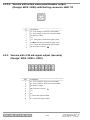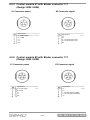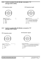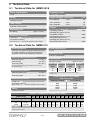
1
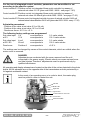
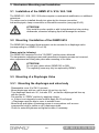
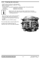
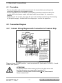
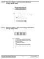
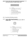
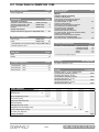
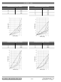
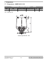
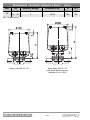
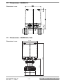
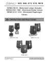
563, 568, 613, 618, 9618
GEMÜ 9618 - Motorized Linear Actuator
GEMÜ 563 / 568 - Motorized Globe Valves
GEMÜ 613 / 618 - Motorized Diaphragm
Valves
GB
OPERATING INSTRUCTIONS
GEMÜ 563 / 568
GEMÜ 613 / 618
GEMÜ 9618
563, 568, 613, 618, 9618
Table of Contents
1
2
3
4
5
6
7
Safety Guidelines
. . . . . . . . . . . . . . . . . . . . . . . . . . .3
1.1 General
. . . . . . . . . . . . . . . . . . . . . . . . . . .3
1.2 Explanation of Symbols and Notices
. . . . . . . . . . . . . . . . . . . . . . . . . . .3
1.3 Safety Notices
. . . . . . . . . . . . . . . . . . . . . . . . . . .3
1.4 Intended Use
. . . . . . . . . . . . . . . . . . . . . . . . . . .4
1.5 Tools Required for Installation and Connection
. . . . . . . . . . . . . . . . . . . . . . . . . . .4
Manufacturer's Information
. . . . . . . . . . . . . . . . . . . . . . . . . . .4
2.1 Delivery
. . . . . . . . . . . . . . . . . . . . . . . . . . .4
2.2 Functions
. . . . . . . . . . . . . . . . . . . . . . . . . . .4
2.3 Versions
. . . . . . . . . . . . . . . . . . . . . . . . . . .5
2.4 Operation and Adjustment
. . . . . . . . . . . . . . . . . . . . . . . . . . .5
2.4.1 RESET set value input to factory setting for E1/E2/E3 . . . . . . . . . . . . . . . . . .7
2.4.2 Electric closing limit for E1/E2 → reprogramming
position of valve at set value 0 V or 0/4 mA . . . . . . . . . . . . . . . . . . . . . . . . . .7
2.4.3 Electric opening limit for E1/E2 → reprogramming
position of valve at set value 20mA
. . . . . . . . . . . . . . . . . . . . . . . . . . .8
2.4.4 Setting the dead zone
. . . . . . . . . . . . . . . . . . . . . . . . . . .8
Mechanical Mounting and Installation
. . . . . . . . . . . . . . . . . . . . . . . . . . .9
3.1 Installation of the GEMÜ 613 / 618 / 563 / 568
. . . . . . . . . . . . . . . . . . . . . . . . . . .9
3.2 Mounting / Installation of the GEMÜ 9618
. . . . . . . . . . . . . . . . . . . . . . . . . . .9
3.3 Mounting of a Diaphragm Valve
. . . . . . . . . . . . . . . . . . . . . . . . . . .9
3.3.1 Mounting the diaphragm and valve body . . . . . . . . . . . . . . . . . . . . . . . . . . .9
3.3.2 Checking the valve seal
. . . . . . . . . . . . . . . . . . . . . . . . . .10
Electrical Connections
. . . . . . . . . . . . . . . . . . . . . . . . . .11
4.1 Procedure
. . . . . . . . . . . . . . . . . . . . . . . . . .11
4.2 Connection Diagram
. . . . . . . . . . . . . . . . . . . . . . . . . .11
4.2.1 Internal Wiring Diagram with Connection to Terminal Strip . . . . . . . . . . . . .11
4.2.1.1 Standard version - with limit switch feedback . . . . . . . . . . . . . . . . .12
4.2.1.2 Standard version - with actual value potentiometer . . . . . . . . . . . .12
4.2.2 Connection with Harting Connector
. . . . . . . . . . . . . . . . . . . . . . . . . .13
4.2.2.1 Version with limit switch feedback
with Harting connector HAN 7 D . . . . . . . . . . . . . . . . . . . . . . . . . .13
4.2.2.2 Version with actual value potentiometer
output with Harting connector HAN 7 D . . . . . . . . . . . . . . . . . . . . .14
4.2.3 Control module E1 with Binder connector 717 . . . . . . . . . . . . . . . . . . . . . . .15
4.2.4 Control module E2 with Binder connector 717 . . . . . . . . . . . . . . . . . . . . . . .15
4.2.5 Control module E3 with Binder connector 717 . . . . . . . . . . . . . . . . . . . . . . .16
4.2.6 Control module EP with Binder connector 717 . . . . . . . . . . . . . . . . . . . . . . .16
Technical data
. . . . . . . . . . . . . . . . . . . . . . . . . .17
5.1 Technical data for GEMÜ 9618
. . . . . . . . . . . . . . . . . . . . . . . . . .17
5.2 Technical data for GEMÜ 613
. . . . . . . . . . . . . . . . . . . . . . . . . .17
5.3 Technical data for GEMÜ 618
. . . . . . . . . . . . . . . . . . . . . . . . . .18
5.4 Technical data for GEMÜ 563 / 568
. . . . . . . . . . . . . . . . . . . . . . . . . .18
Order data
. . . . . . . . . . . . . . . . . . . . . . . . . .19
6.1 Order data for GEMÜ 9618
. . . . . . . . . . . . . . . . . . . . . . . . . .19
6.2 Order data for GEMÜ 613
. . . . . . . . . . . . . . . . . . . . . . . . . .20
6.3 Order data for GEMÜ 618
. . . . . . . . . . . . . . . . . . . . . . . . . .21
6.4 Order data for GEMÜ 563 / 568
. . . . . . . . . . . . . . . . . . . . . . . . . .23
Dimensions
. . . . . . . . . . . . . . . . . . . . . . . . . .25
7.1 Dimensions - GEMÜ 9618 / 618
. . . . . . . . . . . . . . . . . . . . . . . . . .25
7.2 Dimensions - GEMÜ 613
. . . . . . . . . . . . . . . . . . . . . . . . . .27
7.3 Dimensions - GEMÜ 563 / 568
. . . . . . . . . . . . . . . . . . . . . . . . . .27
563, 568, 613, 618, 9618
2/28
1 Safety Guidelines
Please read the following instructions carefully and always comply with them.
1.1 General
In order for the motorized linear actuator to function properly, the following conditions must
be fulfilled:
· proper transportation and storage
· installation and startup by trained personnel
· operation in accordance with these operating instructions
· proper maintenance
Therefore, you must observe
· the information contained in these operating instructions
· the relevant safety regulations for the installation and operation of electric
systems
· that this device must not be used in areas exposed to the danger of explosion.
The regulations, standards and directives mentioned in these operating instructions only
apply for Germany. If the GEMÜ 9618 (563 / 568 / 613 / 618) linear actuator is used in
other countries, the applicable local regulations must be observed.
1.2 Explanation of Symbols and Notices
Important information in these operating instructions is emphasized by the
following symbols:
This symbol indicates a potential danger.
Endangerment of human life or health and/or considerable
material damage can occur if these instructions are not observed.
This symbol indicates Notices that provide important information on
your GEMÜ 9618 (563 / 568 / 613 / 618) geben.
1.3 Safety Notices
DANGER!
Electric shock can cause serious burns and fatal injuries!
· Only qualified and trained electricians are permitted to install,
connect and start up the GEMÜ 9618 (563 / 568 / 613 / 618)
· Make sure that the host devices are electrically safe
· Ensure compliance with the electrical data requirements
3/28
563, 568, 613, 618, 9618
1.4 Intended Use
The GEMÜ 9618 is a motorized linear actuator for mounting on diaphragm valves (GEMÜ
613 / 618) or globe valves / control valves (GEMÜ 563 / 568). The actuator performs a
linear movement of max. 5.5 mm, which is transferred to the diaphragm or the regulating
cone of the valve body by means of a spindle.
The actuator is built to protection class IP65.
1.5 Tools Required for Installation and Connection
· Screwdriver (3 mm flat head) for connecting power supply and signal cable to the
standard version terminal strip
· Screwdriver for mounting the socket connector, if applicable (depending on version)
· 10 mm open-end wrench for cover
· 7 mm open-end wrench
· 3 mm hexagon allen key
2 Manufacturer's Information
2.1 Delivery
Inspect the product immediately upon delivery for missing parts or damage.
The delivery documents indicate the scope of delivery.
Compare the order numbers to determine that the correct version has been
delivered and that the order is complete.
The actuator is already checked at the factory for function.
2.2 Functions
The motorized linear actuator is driven by means of a synchronous motor.
The power supply voltage must be 24 V AC, 120 V AC or 230 V AC, 50 / 60 Hz, depending
on the version (voltage tolerance: +10%).
The change in frequency from 50 to 60 Hz results in reduction of the stroke time by 20%.
The motor drives a spur gear. This is available with two different speeds:
17 sec. or 45 sec.
A cam is integrated in the spur gear that transfers a stroke of max. 5.5 mm to the
valve spindle.
The valve spindle is pressed non-directly via a spring against the cam. This ensures
opening even when there is a vacuum.
The shape of the cam is such that in the final stroke area there is a slight increase in the
stroke with the same rotary angle.
The valve end travel positions "OPEN" and "CLOSED" are achieved by limit switches.
These are actuated by two trigger cams attached to the position indicator.
563, 568, 613, 618, 9618
4/28
The micro-switches (change-over contact) are wired internally as follows:
The break contact (to which the A.C. voltage is connected) switches to open position when
the trigger cam is actuated and the power supply is interrupted.
The make contact is closed, which allows a limit switch signal to be picked up
(e.g.: activation of a signal lamp by means of a separate power supply).
The potentiometer installed at the factory enables infinite adjustment of the actuator.
In addition, the actuator can be equipped with an integrated positioner (code E1 / E2),
which can be controlled with a signal from 0 - 10 V or 0 / 4 - 20 mA as the set value.
Instead of the positioner, a process controller E3 can also be installed.
In this case, both the set value and the actual value can be defined externally
as a standard signal 0/4-20 mA.
At a defined set value of 0 V and 0/4 mA the actuator runs to the CLOSED position and at
10V and 20 mA to the OPEN position.
The version without a control module is connected to the terminal strip by means of cable
glands; the version with a control module (code E1, E2 or E3) makes use of socket
connectors.
2.3 Versions
The actuator is available in the following versions:
GEMÜ 9618:
GEMÜ 613:
GEMÜ 618:
GEMÜ 563:
GEMÜ 568:
actuator without mounted valve body (e.g. as replacement actuator)
actuator with mounted plastic valve body (diaphragm valve)
actuator with mounted metal valve body (diaphragm valve)
actuator with mounted plastic valve body with regulating cone (globe valve)
actuator with mounted metal valve body with regulating cone (globe valve)
All models are available in the standard version (OPEN - CLOSED), optionally with or
without potentiometer or with an integrated control module (code E1, E2 or E3).
The operating time of the transmission can be either 17 sec. or 45 sec.
Detailed information on the various versions can be found in the order specifications
(see page 19-23).
2.4 Operation and Adjustment
The GEMÜ 9618 actuator is manufactured without a valve body and is delivered in
"CLOSED" position. Depending on the desired use, either a diaphragm valve or a control
valve must be mounted under the actuator (see chapter 3).
The GEMÜ 613 / 618 / 563 / 568 motorized valves are set in the "OPEN" position when
delivered. No additional parts are required before installing the unit directly into the system.
5/28
563, 568, 613, 618, 9618
For the use of integrated control modules, parameters can be modified or set
according to the specific system:
Control module E1: Position control via integrated three-point controller by means of
external set value 0-10 V (plus code 6025 / 6026 - see page 17-23)
Control module E2: Position control via integrated three-point controller by means of
external set value 0/4-20mA (plus code 6025 / 6026 - see page 17-23)
Control module E3: Process control via integrated controller by means of external set value 0/4-20 mA
external actual value definition 0/4-20 mA (plus code 6023 / 6024 - see p. 17-23)
Adjustable parameters:
· Position of the valve at set value 0 V or 0/4 mA
· Position of the valve at set value 10 V or 20 mA
· Dead zone from ± 0.5 % to ± 5 %
The following factory settings are programmed:
Set value input 0 V
corresponds to
at E1
10 V
corresponds to
0 % valve stroke
100 % valve stroke
Set value input
at E2 / E3
4 mA
20 mA
corresponds to
corresponds to
0 % valve stroke
100 % valve stroke
Dead zone
Position A
corresponds to
±3.5 %
The settings can be changed by means of the control elements, which are visible when the
motor cover is removed.
DANGER!
Adjustments are conducted with the cover removed and the unit
connected to the power supply. Electric shock can cause serious burns
and fatal injuries.Therefore, adjustments must be performed only by
qualified electricians.
All operating and display elements are located on the side of the unit as depicted in the photo
below. All live elements are on the opposite side of the transmission and are protected by a
foil against accidental contact.
In the event of an operating error or in order to abort, the mains plug
must be pulled in order to restart the unit.
Left LED
Middle LED
Right LED
Upper button
16-level switch for dead zone
Lower button
Slide switch SB30
563, 568, 613, 618, 9618
6/28
The slide switch should remain in the left position.
If it is pushed to the right, the factory setting (set value 0-10 V / 4-20 mA) could be lost
→ If recalibrated, a signal with 0/4 mA and 20 mA would have to be fed.
2.4.1 RESET set value input to factory setting for E1/ E2 / E3
· Operating condition
→ middle LED lit (on)
· Press upper and lower buttons longer than 0.5 sec.
→ left and right LED lit (on); middle LED flashes
· Press upper and lower buttons longer than 0.5 sec.
→ left and right LED lit (on); middle LED flickers
→ factory setting detected
· Press upper and lower buttons longer than 0.5 sec.
→ middle LED lit (on)
→ Factory setting is saved.
· Check the new setting by changing the signal
2.4.2 Electric closing limit for E1 / E2 → reprogramming
position of valve at set value 0 V or 0/4 mA
· Operating condition
→ middle LED lit (on)
· Press lower button longer than 0.5 sec.
→ right LED lit (on); middle LED flashes
· Apply electric signal and change it so that the motor runs to the desired position
· Press lower button longer than 0.5 sec.
→ right LED lit (on); middle LED flickers
→ new position of the valve for 0/4 mA is detected
· Press lower button longer than 0.5 sec.
→ middle LED lit (on)
→ new position of the valve for 0/4 mA is saved
· Check the new setting by changing the signal
If the new valve position is not okay with a set value of 0 / 4 mA or 0 V, a RESET must be
conducted (see 2.4.1) and the entire programming process must be repeated.
7/28
563, 568, 613, 618, 9618
2.4.3 Electric opening limit for E1 / E2
→ reprogramming position of valve at set value 20 mA
· Operating condition
→ middle LED lit (on)
· Press upper button longer than 0.5 sec.
→ right LED lit (on); middle LED flashes
· Apply electric signal and change it so that the motor runs to the desired position
· Press upper button longer than 0.5 sec.
→ left LED lit (on); middle LED flickers
→ new position of the valve for 20 mA is detected
· Press upper button longer than 0.5 sec.
→ middle LED lit (on)
→ new position of the valve for 20 mA is saved
· Check the new setting by changing the signal
If the new valve position is not okay with a set value of 20 mA or 10 V, a RESET must be
conducted (see 2.4.1) and the entire programming process must be repeated.
2.4.4 Setting the dead zone
· Operating condition
→ middle LED lit (on)
· Set 16-level rotary switch to desired position:
Position
0
1
2
3
4
5
6
7
8
9
A
B
C
D
E
F
Dead zone
± 0.5 %
± 0.8 %
± 1.1 %
± 1.4 %
± 1.7 %
± 2.0 %
± 2.3 %
± 2.6 %
± 2.9 %
± 3.2 %
± 3.5 %
± 3.8 %
± 4.1 %
± 4.4 %
± 4.7 %
± 5.0 %
· Press upper or lower button for less than 0.5 sec.
→ middle LED lit (on)
→ new dead zone was saved
563, 568, 613, 618, 9618
8/28
3 Mechanical Mounting and Installation
3.1 Installation of the GEMÜ 613 / 618 / 563 / 568
The GEMÜ 613 / 618 / 563 / 568 valves require no mechanical modification or additional
extensions.
The valves can be installed directly into pipes by the chosen connection:
butt weld spigots, clamp connections or threaded connection (see page 20-23).
ATTENTION!
Only install the valve upright or with its leak detection hole pointing
downwards, otherwise escaping liquid will damage the actuator.
3.2 Mounting / Installation of the GEMÜ 9618
The GEMÜ 9618 motorized linear actuator can be mounted to a diaphragm valve
(corresponding to a GEMÜ 613 or 618).
Please note the following:
The GEMÜ 9618 actuator is in the "CLOSED" position when delivered.
The transmission adjusting screws and transmission fastening screws are loosened,
since adjustment and fixing take place after mounting of the valve.
ATTENTION!
Do not open globe valves (GEMÜ 563 or 568).
The regulating cone may only be replaced by GEMÜ.
3.3 Mounting of a Diaphragm Valve
3.3.1 Mounting the diaphragm and valve body
· Disassemble cover (2 x SW 10 screws)
· Mount diaphragm and turn until it stops (do not turn too far!)
· Turn diaphragm back min. 90°, but max. 270°, so that the diaphragm tab lines up
with the groove
· Put actuator in "OPEN" position by applying voltage
or, if there is an integrated control module apply the 20 mA signal
→ Diaphragm must be able to move in actuator base
· Mount body and tighten 4 fastening screws in cross pattern until an even
compression bulge is visible on all 4 diaphragm sides
· Check for external tightness and tighten screws, if necessary
9/28
563, 568, 613, 618, 9618
3.3.2 Checking the valve seal
· Install actuator into pipe (or testing device)
· Apply operating pressure to valve (P = 6 bar)
· Check / set seal:
- by alternately turning both transmission adjusting screws 1 (see photo below)
clockwise
- tightness is increased
anticlockwise
- tightness is decreased
Set the seal of the valve only as high as absolutely necessary.
Setting the seal too high causes unnecessary wear on the actuator
→ decreasing the life
· after checking the seal, both transmission
fastening screws 2 must be tightened
in order to fix the transmission (see photo
on right)
· Replace cover (2 x SW10 screws)
2
On an actuator with a control module, the
screws must be tightened from the
opposite side, due to the additional plates.
2
1
1
2
563, 568, 613, 618, 9618
10/28
2
4 Electrical Connections
4.1 Procedure
· The on-site cable ends must be connected to the terminal strip according to the
connection diagram for the standard version
· For the integrated control modules, the included connectors must be wired to the
on-site cable ends (power supply and signal cable) according to the connection
diagram
· Depending on the version, there may be one or two socket connectors on the housing;
for the power supply - labelled with the voltage type - and for the signal line
4.2 Connection Diagram
4.2.1 Internal Wiring Diagram with Connection to Terminal Strip
open
synchr.
motor
closed
red
yellow
green
closed
blue
black
brown
open
Actual
value pot.
A built-in potentiometer
is required only if the
actual value/set value
comparison between
three-level controller and
valve position takes
place. The limit switches
must not be connected
during installation of the
potentiometer.
Diagram shows CLOSED position - cam has actuated S2 (limit switch CLOSED) → break
contact was opened.
ATTENTION!
The potentiometer will be destroyed if both the limit switch and
the potentiometer are connected to terminals 5-8.
Therefore, connect either the limit switch or the potentiometer!
Never connect both!
11/28
563, 568, 613, 618, 9618
4.2.1.1 Standard version - with limit switch feedback
(Design: 6023 / 6024)
Description
L1, motor voltage for direction of travel OPEN
L1, motor voltage for direction of travel CLOSED
N, reference voltage
, PE protective conductor
L1, S2 (23) end position CLOSED
Us, S2 (24) end position CLOSED
L1, S1 (24) end position OPEN
Us, S1 (23) end position OPEN
4.2.1.2 Standard version - with actual value potentiometer
(Design: 6025 / 6026)
Description
L1, motor voltage for direction of travel OPEN
L1, motor voltage for direction of travel CLOSED
N, reference voltage
, PE protective conductor
n.c.
Us -, actual value potentiometer signal voltage
Us
, actual value potentiometer signal output
Us + , actual value potentiometer signal voltage
563, 568, 613, 618, 9618
12/28
4.2.1.3 Version with actual value potentiometer output and
limit switch feedback CLOSED; Design: 6442
Description
L1, motor voltage for direction of travel OPEN
L1, motor voltage for direction of travel CLOSED
N, reference voltage
PE, protective conductor
L1, S2 (23) end position CLOSED
Us -, actual value potentiometer signal voltage
Us
, actual value potentiometer signal output
Us +, actual value potentiometer signal voltage
Us, S2 (24) end position CLOSED
4.2.2 Connection with Harting connector
4.2.2.1 Version with limit switch feedback
(Design: 6023 / 6024) with Harting connector HAN 7 D
(Design: 6734)
Description
L1, motor voltage for direction of travel OPEN
L1, motor voltage for direction of travel CLOSED
N, reference voltage
Us, S2 (23) end position CLOSED
L1, S2 (24) end position CLOSED
Us, S1 (23) end position OPEN
L1, S1 (24) end position OPEN
PE, protective conductor
13/28
563, 568, 613, 618, 9618
4.2.2.2 Version with actual value potentiometer output
(Design: 6025 / 6026) with Harting connector HAN 7 D
Description
L1, motor voltage for direction of travel OPEN
L1, motor voltage for direction of travel CLOSED
N, reference voltage
n.c.
Us -, actual value potentiometer signal voltage
Us
, actual value potentiometer signal output
Us +, actual value potentiometer signal voltage
PE, protective conductor
4.2.3 Version with 4-20 mA signal output (two-wire)
(Design: 6025 / 6026 + 2422)
Description
L1, motor voltage for direction of travel OPEN
L1, motor voltage for direction of travel CLOSED
N, reference voltage
PE, protective conductor
n.c.
n.c.
I-, actual value output 4-20mA
I+, actual value output 4-20mA
563, 568, 613, 618, 9618
14/28
4.2.4 Control module E1 with Binder connector 717
(Design: 6025 / 6026)
X1 Connector power
X2 Connector signal
Signal name
Signal name
L1, power supply
N, neutral
n.c.
n.c.
PE
n.c.
n.c.
U-, set value input 0-10V
U+, set value input 0-10V
PE
4.2.5 Control module E2 with Binder connector 717
(Design: 6025 / 6026)
X2 Connector signal
X1 Connector power
Signal name
Signal name
L1, power supply
N, neutral
n.c.
n.c.
PE
n.c.
n.c.
I-, set value input 0/4-20mA
I+, set value input 0/4-20mA
n.c.
15/28
563, 568, 613, 618, 9618
4.2.6 Control module E3 with Binder connector 717
(Design: 6023 / 6024)
X1 Connector power
X2 Connector signal
Signal name
Signal name
L1, power supply
N, neutral
n.c.
n.c.
PE
I-, Actual value input 0/4-20mA
I+, Actual value input 0/4-20mA
U-, Set value input 0/4-20mA
U+, Set value input 0/4-20mA
n.c.
4.2.7 Control module EP with Binder connector 717
(Design: 6023 / 6024)
X1 Connector power
X2 Connector signal
Signal name
Signal name
L1, power supply
N, neutral
n.c.
n.c.
PE
n.c.
PE
563, 568, 613, 618, 9618
16/28
Set value potentiometer signal voltage Set value potentiometer signal voltage +
Set value potentiometer signal
5 Technical Data
5.1 Technical Data for GEMÜ 9618
Power consumption
Protection class
3.5 VA
IP 65 acc. to DIN 40050
Rating
Supply voltages / frequency
Code
Continuously rated
24 V 50/60 Hz
±10%
C4
Load resistor
120 V 50/60 Hz
±10%
G4
230 V 50/60 Hz
±10%
L4
32 Ω (with reverse diode)
Design
Operating time
See design
appr. 17 or 45 s
Electrical connection
2 x PG 13,5
(Design without integrated control module)
2 x Circular connector
(Binder Series 717)
(Design with integrated control module)
Code
Standard: approx. 17 sec. operating time,
2 switching contacts
6023
Operating time approx. 45 sec.
2 switching contacts
6024
Operating time approx. 17 sec.,
with potentiometer 10 kΩ
6025
Operating time approx. 45 sec.,
with potentiometer 10 kΩ
6026
5.2 Technical Data for GEMÜ 613
Working medium
Power consumption
Corrosive, inert, gaseous and liquid media which have
no negative impact on the physical and chemical
properties of the body and diaphragm materials.
3.5 VA
IP 65 acc. to DIN 40050
Working medium temperature
Valve body PVC-U
5 to 60° C
Valve body PP
5 to 80° C
Valve body PVDF
Protection class
-20 to 80° C
Operating time
See type of design
Nominal size Operating pressure
The permissible operating pressure depends on the working
medium temperature.
Ambient temperature
Valve body PVC-U / PP
5 to 60° C
Valve body PVDF
-20 to 60° C
(mm)
(bar)
(m3/h)
(g)
12
15
0-6
0-6
2.8
3.5
1000
1050
Diaphragm material
O-ring material
NBR
FPM
EPDM
PTFE
EPDM
FPM
EPDM
FPM
2 x Circular connector
(Design with integrated control module)
Rating
Continuously rated
Weight
O-ring material for valve bodies
with union ends
(Design without integrated control module)
(Binder Series 717)
Kv value
All pressures are given as gauge pressures when applied
upstream only.
Electrical connection
2 x PG 13.5
appr. 17 or 45 s
Other combinations upon request
Pressure / temperature correlation for plastic
Temperature in °C
(plastic body)
-20
-10
±0
Valve body material
PVC-U
PP
PVDF
Code 1
Code 5
Code 20
5
10
20
25
30
40
50
60
70
80
0.9
2.4
3.8
1.6
3.2
0.9
2.8
permissible operating pressure in bar
6.0
6.0
6.0
6.0
6.0
6.0
6.0
6.0
6.0
6.0
6.0
6.0
6.0
6.0
6.0
4.8
5.1
5.4
3.6
4.2
4.8
2.1
3.3
4.3
Data for extended temperature ranges on request.
Please note that the ambient temperature and medium temperature generate a combined temperature at the valve body which must not
exceed the above values.
17/28
563, 568, 613, 618, 9618
5.3 Technical Data for GEMÜ 618
Working medium
Load resistor
Corrosive, inert, gaseous and liquid media which have
no negative impact on the physical and chemical
properties of the body and diaphragm material.
32 Ω (with reverse diode)
Temperature of working medium
Direct mount (actuator design 2)
With distance piece (actuator design 1+3)
Operating time
+ 60° C
+130° C
See design
Ambient conditions
Ambient temperature
approx. 17 or 45 s
Protection class
-15 to +55° C
IP 65 acc. to DIN 40050
Power consumption
Electrical connection
3.5 VA
2 x PG 13.5
Rating
2 x Circular connector
Continuously rated
Diaphragm size
(Design without integrated control module)
(Binder Series 717)
(Design with integrated control module)
Nominal size
Operating pressure
Kv value*
Weight
[mm]
[bar]
[m /h]
[g]
004
006
008
010
015
10
12
15
20
8
10
3
2.2
3.3
4.0
-
0-6
0-6
1100
1330
All pressures are gauge pressures. Operating pressure values were determined with static operating pressure applied on one side of a
closed valve. Sealing at the valve seat and atmospheric sealing is ensured for the given values.
Information on operating pressures applied on both sides and for high purity media on request.
*Given Kv values are valid for ISO valve body connection, EPDM diaphragm material.
Kv values determined at p1 = 6 bar, EPDM diaphragm material. Kv-values: Tolerance ±10%.
5.4 Technical Data for GEMÜ 563 / 568
Working medium
Input resistance
Corrosive, inert, gaseous and liquid media which have no
negative impact on the physical and chemical properties of
the body and seal material.
Leakage rate
at 6 bar acc. to DIN 3230,
T.3: Leakage rate 3 (test with water)
Max. permissible temp. of working medium
GEMÜ 563:
See data sheet "Technical Information on Plastic Materials“
GEMÜ 568:
80° C
33 Ω (input protected by reverse diode)
Operating time
See design
approx. 17 or 45 s
Protection class
IP 65 acc. to EN 60529
Ambient conditions
Ambient temperature
-15 to +55° C
For limitations see table Pressure/temperature correlation
Nominal
size
Operating
pressure
DN
[bar]
GEMÜ 563
GEMÜ 568
3, 6, 10, 15
0-6
1.6
2.4
Weight [kg]
All pressures are gauge pressures.
Electrical connection
2 x PG 13.5
(Design without integrated control module)
2 x circular connector
(Binder Series 717) (Design with integrated control module)
Power supply
24, 120, 230V 50/60 Hz
Rating
Power consumption
Continuously rated
3.5 VA
563, 568, 613, 618, 9618
18/28
± 10%
Pressure / temperature correlation for plastic
Temperature in °C
Plastic body
-20
-10
±0
5
10
Valve body material
20
25
30
40
50
60
70
80
Permissible operating pressure in bar
PVC-U
Code 1
-
-
-
6.0
6.0
6.0
6.0
4.8
3.6
2.1
0.9
-
-
PVDF
Code 20
6.0
6.0
6.0
6.0
6.0
6.0
6.0
5.4
4.8
4.3
3.8
3.2
2.8
Data for extended temperature ranges on request. Please note that the ambient temperature and medium temperature generate a combined
temperature at the valve body which must not exceed the above values.
6 Order Data
6.1 Order Data for GEMÜ 9618
Diaphragm size
Code
Diapragm size 8
Diapragm size 10
Connection type
8
10
Code
For M-blocks
For D-valve
For T-valve
M
D
T
Adapter
Code
Diaphragm size 8 (absolutely necessary)
Diaphragm size 10
(optionally defined by K-number 6164)
A
-
Supply voltage / frequency
24 V 50/60 Hz
120 V 50/60 Hz
230 V 50/60 Hz
Code
±10%
±10%
±10%
C4
G4
L4
Integrated control modules (with connectors)
Code
Without
-
Analogue signal processing
Control of valve position. Actual value control inside the actuator by potentiometer
(K 6025 / K 6026); set value external, 0 - 10 V
Control of valve position. Actual value control inside the actuator by potentiometer
(K 6025 / K 6026); set value external, 0/4-20 mA
Control of process variables. Actual value external, 0/4-20 mA, set value external, 0/4-20 mA (K 6023 / K 6024)
Control of valve position. Actual value control inside the actuator by potentiometer
(K 6025 / K 6026); set value external, external potentiometer
Design
E1
E2
E3
EP
Code
Standard: approx. 17 sec. operating time, 2 switching contacts
6023
Operating time approx. 45 sec., 2 switching contacts
6024
Operating time approx. 17 sec., with 10 kΩ potentiometer
6025
Operating time approx. 45 sec., with 10 kΩ potentiometer
6026
Order example
9618
Type
9618
Diaphragm size (code)
8
M
A
C4
E2
6025
8
Connection type (code)
M
Adapter (code)
A
Supply voltage / Frequency (code)
C4
Integrated control modules (code)
E2
Design (K-No.)
6025
19/28
563, 568, 613, 618, 9618
6.2 Order Data for GEMÜ 613
Body configuration
Code
Straight through
D
Connection
Code
Threaded sockets - DIN ISO 228
1
Solvent cement sockets - DIN (only with PVC-U)
2
Union ends with metric sockets - DIN
Diaphragm material
Code
NBR
FPM
2
4
EPDM
14
PTFE/EPDM
PTFE laminated
52
7
Spigots for butt welding (only with PVDF)
28
Union ends with metric butt weld spigots acc. to
DIN 16962 T 13 series 4 (only with PP and PVDF)
78
Valve body material
Code
Supply voltages / Mains frequency Code
PVC-U, grey
1
24 V 50/60 Hz
±10%
C4
PP
5
120 V 50/60 Hz
230 V 50/60 Hz
±10%
±10%
G4
L4
PVDF
20
Integrated control modules with connectors
Code
Without
-
Analogue signal processing
Control of valve position. Actual value control inside the actuator by means of a potentiometer
(K 6025/K 6026); set value external, 0-10 V
Control of valve position. Actual value control inside the actuator by means of a potentiometer
(K 6025/K 6026); set value external, 0/4-20 mA
Control of process variables. Actual value external, 0/4-20 mA; set value external, 0/4-20 mA (K 6023/K 6024)
E2
E3
Control of valve position. Actual value control inside the actuator by means of a potentiometer
(K 6025/K 6026); set value external, external potentiometer
EP
Design
Code
Standard: approx. 17 sec. operating time,
2 potential-free switching contacts
Operating time approx. 45 sec.,
2 potential-free switching contacts
Operating time approx. 17 sec.,
with potentiometer 10 kΩ
Operating time approx. 45 sec.,
with potentiometer 10 kΩ
Order example
613
Type
613
Nominal size (mm)
Body configuration (code)
Connection (code)
Valve body material (code)
Diaphragm material (code)
Supply voltage / frequency (code)
Integrated control modules (code)
Design (additional K code)
Integrated mounting plate (code)
563, 568, 613, 618, 9618
Integrated mounting plate
E1
Code
6023
With integrated mounting plate
M
6024
Without mounting plate
O
6025
Without mounting plate
-
Material code 20
Material code 20
Material code 1 and 5
6026
15
15
D
D
7
7
20/28
1
1
14
14
C4
C4
E2
E2
6023
6023
M
M
6.3 Order Data for GEMÜ 618
Body configuration
Code
Valve body material
Code
Tank valve body
B**
MS
2/2-way
D
Multi-port design
M**
1.4435 (ASTM A 351 CF3M) Investment casting* 34
T body
T*
* For dimensions see T Valves brochure
** Dimensions and versions on request or according to customer
requirements
Connection
Brass
12
1.4435 (316 L)
Forged body
40
1.4435 (316 L)
Block material**
41
* Material equivalency 316L
** only for body configuration B, M and T
Code
Butt weld spigots
Spigots DIN
Spigots DIN 11850, series 1
Spigots DIN 11850, series 2
Spigots DIN 11850, series 3
Spigots DIN 11866, series A
Spigots JIS-G 3459
Spigots BS 4825, Part 1
Spigots ASME BPE
Spigots EN ISO 1127
Threaded connections
Threaded sockets DIN ISO 228
Threaded spigots to DIN 11851
One side threaded spigot (to DIN 11851)
other side cone spigot with union nut
(to DIN 11851)
Aseptic unions upon request
Clamp connections
Clamp ASME BPE for pipe ASME BPE,
length ASME BPE
Clamp following ASME BPE for pipe
EN ISO 1127, length EN 558-1 series 7
Clamp ASME BPE for pipe ASME BPE length
EN 558-1, series 7
Clamp DIN 32676 for pipe DIN 11850 length
EN 558-1, series 7
0
16
17
18
1A
36
55
59
60
1
6
62
Diaphragm material
Code
4, 4A**
FPM
EPDM
max. 130°C*
12
EPDM
max. 150°C*
13, 3A**
EPDM
max. 150°C*
16, 6A**
EPDM
max. 150°C*
17**
PTFE laminated max. 150°C* 52, 5A**
PTFE/EPDM
Materials comply with FDA requirements, except code 4, 4A
* Steam sterilisation temperature (valid for actuator sizes 1 + 3
- see dimensions)
** for actuator size 1 (see dimensions)
80
82
88
8A
For overview of available valve bodies see datasheet page 8
Supply voltages / frequency
Code
24 V 50/60 Hz
±10%
C4
120 V 50/60 Hz
±10%
G4
230 V 50/60 Hz
±10%
L4
Integrated control modules with connectors
Code
Without
-
Analogue signal processing
Control of valve position. Actual value control inside the actuator by means of a potentiometer
(K 6025/K 6026); set value external, 0-10 V
Control of valve position. Actual value control inside the actuator by means of a potentiometer
(K 6025/K 6026); set value external, 0/4-20 mA
Control of process variables. Actual value external, 0/4-20 mA; set value external, 0/4-20 mA (K 6023/K 6024)
E2
E3
Control of valve position. Actual value control inside the actuator by means of a potentiometer
(K 6025/K 6026); set value external, external potentiometer
EP
21/28
E1
563, 568, 613, 618, 9618
Design
Code
Standard: approx. 17 sec. operating time, 2 switching contacts
6023
Operating time approx. 45 sec., 2 switching contacts
Operating time approx. 17 sec., with 10 kΩ potentiometer
6024
6025
Operating time approx. 45 sec., with 10 kΩ potentiometer
6026
Valve surface finishes, internal finish
Code
Ra ≤ 6.3 μm
blasted internal/external
1500*
Ra ≤ 6.3 μm
electropolished internal/external
1509*
Ra ≤ 0.8 μm
mechanically polished internal, blasted external
1502
Ra ≤ 0.8 μm
electropolished internal/external
1503
Ra ≤ 0.6 μm
mechanically polished internal, blasted external
1507
Ra ≤ 0.6 μm
electropolished internal/external
1508
Ra ≤ 0.4 μm
mechanically polished internal, blasted external
1536
Ra ≤ 0.4 μm
electropolished internal/external
1537
Ra ≤ 0.25 μm
mechanically polished internal, blasted external
1527
Ra ≤ 0.25 μm
electropolished internal/external
1516
Ra acc. to DIN 4768; at defined reference points
* only in investment cast design
The available internal surface finishes are dependent on the inside diameter and the body production procedure.
Actuator
K-no.
Without metal distance piece
-
With metal distance piece (see actuator design 3 / dimensions) with diaphragm size 10
6164
With metal distance piece (see actuator design 1 / dimensions) with diaphragm size 8
-
Order example
618
Type
Nominal size (mm)
Body configuration (code)
Connection (code)
Valve body material (code)
Diaphragm material (code)
Supply voltage / frequency (code)
Integrated control modules (code)
Design (code)
Surface finish (code)
Actuator (K-no.)
618
563, 568, 613, 618, 9618
10
10
D
D
60
60
22/28
34
34
13
13
L4
L4
-
-
6023 1516 6164
6023
1516
6164
6.4 Order Data for GEMÜ 563 / 568
Body configuration
Control module
Code
Body configuration
D
Connection
Code
Threaded connections
Threaded sockets DIN ISO 228
(GEMÜ 563/568) 1
Threaded spigots DIN 11851
(GEMÜ 568)
6
Union ends with DIN insert
(socket)
(GEMÜ 563)
7
Clamp connections
Clamps DIN 32676 for pipe DIN 11850 (GEMÜ 568)
86
Valve body material
Code
PVC-U, grey
(GEMÜ 563)
1
PVDF
(GEMÜ 563)
20
Code
(with connector)
Without
Analogue signal processing
Control of valve position.
Actual value control inside the actuator
by potentiometer (K 6025/K 6026);
set value external, 0 - 10V
Control of valve position.
Actual value control inside the actuator
by potentiometer (K 6025/K 6026);
set value external, 0/4-20 mA
Control of process variables.
Actual value external, 0/4-20 mA;
set value external, 0/4-20 mA (K 6023/K 6024)
Control of valve position.
Actual value control inside the actuator
by potentiometer (K 6025/K 6026);
set value external, external potentiometer
1.4435 (ASTM A 351 CF3M) investment casting*(GEMÜ 568) 34
Control characteristic
* Material equivalency 316 L
Kv values / control characteristic / equal-percentage
/ equal-percentage
/ equal-percentage
/ linear
/ linear
Seat seal
Code
FPM
4
EPDM
E2
E3
EP
Code
A*
B*
C*
D*
E*
* For selection see diagrams page 4.
Kv value
Code
24V 50/60 Hz ±10%
C4
120V 50/60 Hz ±10%
G4
230V 50/60 Hz ±10%
L4
see diagrams
Kv values: Tolerance ±10%.
Design
K number
Standard: approx. 17 sec. operating time,
2 potential-free switching contacts
Operating time approx. 45 sec.,
2 potential-free switching contacts
Operating time approx. 17 sec.,
with potentiometer 10 kΩ
Operating time approx. 45 sec.,
with potentiometer 10 kΩ
Order example
563
Type
563
Body configuration (code)
E1
14
Voltage/Frequency
Nominal size
-
10
D
1
1
14
L4
E2
B
6023
6024
6025
6026
1600
6025
10
D
Connection (code)
1
Valve body material (code)
1
Seat seal (code)
14
Voltage/Frequency (code)
L4
Integrated control modules (code)
E2
Control characteristic (code)
B
Kv value (see diagrams)
1600
Design (K number)
6025
23/28
563, 568, 613, 618, 9618
Kv values
[l/h]
Characteristics DN 3 (seat)
Characteristic
Kv value
A
63
Characteristics DN 6 (seat)
[l/h]
Characteristic
Kv value
A
100
B
400
160
C
630
D
100
D
250
e
630
Kv value [l/h]
Kv value [l/h]
B
C
Stroke [mm]
Stroke [mm]
Characteristics DN 10 (seat)
Characteristic
[l/h]
250
Kv value
Characteristics DN 15 (seat)
[l/h]
Characteristic
Kv value
1000
A
2500
B
1600
B
3300
D
1600
D
3300
Kv value [l/h]
Kv value [l/h]
A
Stroke [mm]
563, 568, 613, 618, 9618
Stroke [mm]
24/28
[l/h]
7 Dimensions
7.1 Dimensions - GEMÜ 9618 / 618
Dimensions - Actuator design 1
MG
DN
8
004 - 015
[mm]
Actuator design Actuator K-no.
1
-
A
A1
152
44
MG = Diaphragm size
Valve body DN 004 - 015
25/28
563, 568, 613, 618, 9618
Dimensions - Actuator designs 2 and 3
[mm]
MG
DN
Actuator design
Actuator K-no.
A
A1
10
10 - 20
10 - 20
2
3
6164
134
164
25
55
MG = Diaphragm size
Valve body DN 10 - 20
563, 568, 613, 618, 9618
Valve body DN 10 - 20
with metal distance piece
(actuator K-no. 6164)
26/28
7.2 Dimensions - GEMÜ 613
Dimensions in mm
7.3 Dimensions - GEMÜ 563 / 568
223
ø 100
114
Dimensions in mm
27/28
563, 568, 613, 618, 9618
Note:
Connection and adjustment of the machine must be performed only by authorized service personnel.
The manufacturer shall assume no liability for damages resulting from improper use or unauthorized
actions. In case of doubt, please contact us before initial operation.
Note concerning the EC Machinery Directive 2006/42/EC:
A Declaration of Incorporation in accordance with the EC Machinery Directive 2006/42/EC
accompanies this product.
For incorporation in an installation classed as a machine:
The commissioning is prohibited until it has been determined that the machine (plant) in which this
product is to be incorporated complies with the provisions of the EC Machinery Directive
2006/42/EC.
VALVES, MEASUREMENT
AND CONTROL SYSTEMS
GEMÜ Gebr. Müller Apparatebau GmbH & Co. KG · Fritz-Müller-Str. 6-8 · D-74653 Ingelfingen-Criesbach
Telefon +49 (0) 7940/123-0 · Telefax +49 (0) 7940/123-192 · e-mail: [email protected] · http://www.gemue.de
Subject to modifications · 11/2012 · 88237961
*88237961*
Handling, assembly and commissioning, in addition to setting and adjustment of the machine must
be performed only by authorised specialist staff.