1
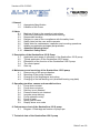
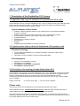
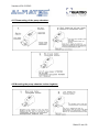
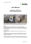
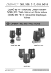
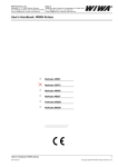
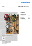
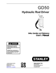
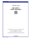
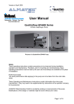
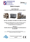
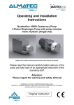
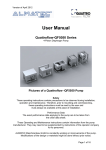
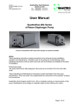
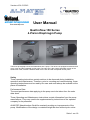
Version of 01.01.2012 Indianapolis ● Chicago ● San Juan www.hollandapt.com User Manual Quattroflow-150 Series 4-Piston Diaphragm Pump These two photographs show the Quattroflow-150 S pump. The left one is equipped a stainless steel motor cover and the integrated control panel. The right one is the system integrable version of the Quattroflow-150S, without a stainless steel motor cover and with a seperate control panel. Safety These operating instructions contain advices to be observed during installation, operation and maintenance. Therefore, prior to mounting and commissioning, these operating instructions must be read by the user and must always be available at the place of installation. Performance Data The exact performance data applying to the pump are to be taken from the order data sheet. These Operating and Maintenance instructions contain information from the pump manufacturer. They may need to be supplemented by instructions of the operator company for its personnel. ALMATEC Maschinenbau GmbH is constantly working on improvements of the pump. Modifications of the design or materials might be done without prior notice. Seite 1 von 18 Version of 01.01.2012 . 1. General 1.1 1.2 Appropriate Specification Labelling of the Pump 2. Safety 2.1 2.2 2.3 2.4 2.5 2.6 2.7 2.9 2.10 Marking of hints in the operating instructions Personnel qualification and personnel training Responsible working Dangers in case of non-compliance with the safety hints Safety hints fort the user and/or operator Safety hints for maintenance, inspection and mounting operations Arbitrary reconstruction and spare part production Attention! Warning hints! Attention! Safety hints! 3. Description of the Quattroflow-150 S Pump 3.1 Application and range of utilization of the Quattroflow-150 S pump 3.2 Typical application of the Quattroflow-150 S pump 3.3 Description of the function of the Quattroflow-150 S pump 3.4 The control panel 3.5 Start-up 4. Maintenance and servicing of the Quattroflow-150 S pump 4.1 Dismounting of the pump chamber 4.2 Mounting of the pump chamber 4.3 Changing of the diaphragms and valves 4.4 Changing of the ball bearing unit (shaft-ball bearing-cap plate) 5. Operating troubles, causes and remedial actions 5.1 Pump does not start 5.2 Pump does not prime 5.3 Delivery is not obtained 5.4 Pressure head is not obtained 5.5 Irregular pump delivery 5.6 Pump operates noisily 5.7 Pump is leaky 5.8 Motor gets to warm 5.9 Display show error code 6. Performance chart of the Quattroflow-150 S pump 6.1 Diagram 1 Discharge as function of pump rpm 7. Technical data of the Quattroflow-150 S pump Seite 2 von 18 Version of 01.01.2012 1. General: 1.1 Appropriate specification This User Manual is valid fort the Quattroflow-150 S pump No liability will be undertaken for any damages caused by non-compliance with the operating instructions and service conditions! Original spare parts serve safety purposes. The use of other parts may cancel the liability for the consequences resulting therefrom. Manufacturer: ALMATEC Maschinenbau GmbH Carl-Friedrich-Gauss-Str. 5 D-47475 Kamp-Lintfort Germany Phone: Fax: e-mail: Internet: +49 2842 961-0 +49 2842 961-40 [email protected] www.quattroflow.com 1.2 Labelling of the pump The type label of each Quattroflow pump can be seen on the bottom of the base plate. Besides the serial No of the pump head is punshed in, at the front cover. Quattroflow-150 S with 50W brushless DC motor in a stainless steel housing Power switch Control panel Power kable The type lable on the bottom of the base plate CE-sign, protection class: IP55 Safty lable: 6 bar ! Do not remove ! Serial No. is punched in, at the front of the pump! Seite 3 von 18 Version of 01.01.2012 2. Safety These operating instructions contain basic hints to be observed during installation, operation and maintenance. Therefore, prior to mounting and commissioning, these operating instructions must by all means be read by the fitter as well as the pertinent expert personnel/customer and must always be available at the place of installation of the pump. Not only are the general safety hints listed under this item “Safety” to be observed, but also the special safety hints such as for specific use at the user’s site. 2.1 Marking of hints in the operating instructions The safety hints contained in these operating instructions which, in case of non-compliance, may cause danger to personnel, are particularly marked with the danger symbol. Safety sign according DIN 4844 - W 9 In case of warning against electric voltage with: Safety sign according DIN 4844 – W8 Safety hints which, in case of non-compliance, may cause danger to the pump itself or to parts of the systems are particularly marked with the word: ATTENTION! Marking labels at the pump e.g. - Pmax 6bar Direction of flow must not be removed and care have to be taken that these labels are readable. 2.2 Safety hints for maintenance, inspection, mounting and operation The customer shall see to it that all maintenance, inspection and mounting operations are performed by authorized and qualified expert personnel who have sufficiently informed themselves by thoroughly studying the operating instructions. Basically, operations at the machine must be performed during standstill only. Pumps handling noxious fluids must be decontaminated. 2.3 Responsible working Please follow strictly the safety guidelines that are issued for your particular enviroment. Eg. the handling of chemicals, like caustic or acid, the handling of biological materials, the handling of tubing, piping, instrumentation, fittings etc. Seite 4 von 18 Version of 01.01.2012 2.4 Dangers in case of non-compliance with safety hints In case of non-compliance with the safety hints may cause danger to personnel, equipment and enviroment. It can cause: - Failure of the proper function of the pump/system. - Danger to personnel by electrical, mechanical, chemical, biological impacts. - Danger to equipment and enviroment 2.5 Safety hints for the user / operator - In case of hot parts (e.g. while CIP or SIP) protective measures have to be taken. - Protecting covers of moving parts (e.g. coupling, cover of motor) must not be removed. - Leakages of dangerous materials to be handled must be discharged so as not to result in danger to persons or he enviroment. Legal stipulations are to be obeserved. - Dangers by electrical energy are to be excluded (for details with regard to hereto, please refer to the regulations of the VDE and the local energy supply associations. 2.6 Safety hints for maintenance, inspection and mounting operations The customer shall see to it that all maintenance, inspection and mounting operations are performed by authorized and qualified expert personnel who have informed themselves by thoroughly studying the operating instructions. Basically operations at the machine must be performed during standstill only. Disconnect mains supply before opening the electrical cabinets (control box). Pumps or aggregates handling noxious fluids (e.g. caustic, bio hazardous) must be decontaminated. Prior to restarting all items and the pump are to be observed. 2.7 Arbitrary reconstruction and spare part construction Reconstruction of or changes to the machine are only admissible after consultation with the manufacturer. Original spare parts and accessories authorized by the manufacturer serve safety purposes. The use of other parts may cancel the liability for the consequences resulting herefrom. 2.8 Inadmissible modes of operation The operating safety of the machine supplied is only ensured with due application according to the operating instructions. The limit values given in the data sheet must by no means exceeded. Seite 5 von 18 Version of 01.01.2012 2.9 Attention! Warning hints! These warning hints are to prevent the user from an inadmissible mode of operation. These warning hints are to be strictly followed to avoid any damage of the pump and/or any danger to personnel. Diapragm pumps are positive displacement pumps and can theoretically generate an infinitely high pressure. With the discharge line closed, e.g. by clogging or by incidental closing of a valve, the pressure generated by the pump may reach a multiple of the admissible pressure of the plant. This may lead to bursting of the diaphragm or lines which must be absolutely avoided especially when handling dangerous products. Diameter of the suction line need to be sufficient to avoid cavitation. The use of a safety device (e.g. pressure switch) can be necessary. Please make sure that prior to the start of the pump the discharge line is checked. Make sure that there is no flow restriction in the discharge line to avoid any over pressure (e.g. closed valve). Check all seals (e.g. TC clamps) before the pump is started. The maximum discharge pressure depends on the temperature of the fluid. pmax at room temperature = 6 barg pmax at 90° C = 3 barg Please allow the pump to cool down after heat treatment (e.g. CIP / SIP). Flush the pump prior to use with appropriate fluid (e.g. buffer) Foundation design: The foundation must be designed so that it can take the weight of the pump aggregate on the entire surface. Please make sure that the pump is operated with the proper mains voltage and frequeny to avoid damages and electrical danger. Due to the versatile possibilities to use the Quattroflow-150 s pump it is highly recommended to check case by case if the Quattroflow-150 S pump will be the right tool for the specific application. The user/operator is responsible to perform a proper method of testing if the pump should be applied for his specific application. The chemical and thermal compatibility of the elastomeric parts of the pump with the fluid that will be pumped are to be checked by the operator before the first process run. E.g. Oily, fatty fluids or solvents might cause a swelling and/or destruction of the elastomeric components. If in doubt, please contact the manufacturer! Operating the pump in humid or aggressive air can cause damages to the motor and control box. The control box should not be exposed to spray/splash water or to heat sources. If the Quattroflow-150 S pump is to be used under rough conditions, the manufacturer can supply special equipment, like motors and controls. Seite 6 von 18 Version of 01.01.2012 2.10 Attention! Safety Hints! The following safety hints notify you of the potential of bodily harm or life danger of the user/operators! Please read and follow the safety hints and warnings to avoid any risk of bodily harm, life danger and/or the damage of equipment. Please keep this User Manual available. Make sure that the operators of the pump have read and understood the User Manual. A training session might be appropriate. We recommend to install specific warning labels at the system. Disconnect mains before doing any maintenance! The housing of the control box is to be opened only by skilled personnel. Check the electrical cables before connecting to mains supply. The Quattroflow-150 S is a positive displacement pump and can theoretically generate an infintely high pressure even at low speed (rpm). Prior to each start of the pump check and make sure that the discharge line is not closed or restricted. The design of the discharge line must not build up a pressure of > 6 barg. If suction and/or discharge line are flexible tubing, then make sure that these tubings do have the proper pressure rating for the full range of temperatures that are applied. pmax. = 6 bar, Do not exceed! Warning Label: p max: bar! Do not remove! If the maximum pressure is exceeded it can happen that the diaphragm of the pump will burst. In this case the fluid will come out of the pump and can cause a danger for the personnel and/or enviroment (e.g. caustic cleaner). The Quattroflow-150 S pump can pump air which means that most of the fluid inside the pump chamber will be pump out. However there will be a residual amount of fluid (appr. 1 – 3 ml) inside the pump chamber that should be flushed out of the pump before the pump will be opened. Please follow the general safety guidelines when handling chemical fluids (wear gloves and/or glasses) before the pump chamber will be opened. Never operate the pump without coupling and motor housing. The foundation must be designed so that it can take the weight of the pump on the entire surface. The Quattroflow-150 S must not be operated in ATEX zones. Special versions for ATEX applicationen are available. Please contact the manufacturer in case that the Quattroflow-150 S pump need to be modified for ATEX applications. ALMATEC Maschinenbau GmbH Attention! Inadmissible modes of operation, arbitrary reconstruction, spare parts production and/or any changes of the design (without admission of the manufacuturer) may cancel the liability for the concequences resulting therefrom. Seite 7 von 18 Version of 01.01.2012 3. Description of the Quattroflow-150 S pump 3.1 Application and range of utilization of the Quattroflow-150 S pump The Quattroflow-150 S is a 4-piston Diaphragm pump, which is mainly used to pump water-like fluids that are typically handled in research-, pilot plant- or production facilities of the pharmaceutical, biotech, food or cosmetic research centers or plants. Typical examples of these fluids: Solutions containing proteins (albumin, IgG, Clotting factors, monoclonale antibodies, enzymes, vaccines.) Solutions of polymers or suspensions (silicons, latex, chromatography media) Cell suspensions (bacteria, yeast, algae, fungi, mammalian cells) Colloidale solutions Suspensions of virusses or phages Dairy products Gelatine Supplements and ingredients for cosmetic and food. 3.2 Typical process steps in which the Quattroflow-150 S pump is used Filtration technology To recirculate feed/retentate (e.g. membrane cassettes, hollow fibre, spiral wound, ceramic elements. Feed pump for filter cartridges or plate and frame depth filters Chromatography: Packing of chromatography columns Feed pump to mix gradients Feed pump for centrifuges or separators Feed pump for filling machines 3.3 Discription of the working princaple Quattroflow-150 S The Quattroflow-150 S pump is a 4-piston diaphragm pump. The 4 diaphragms of the pump oscillate back and forth. This alternate movement is created by a connector plate that is arranged on a ball bearing. The ball bearing sits on an eccentric shaft. The connector plate does not turn! The stroke of the pistons is determined by the angle of the eccenter. There is only eccentric shafts with 5° available. Range of flow rate: 5° eccentric shaft: appr. 1 -150 L/hr at max. 3000rpm Please note: The direction of flow can be adjusted by turning the pump chamber in 90° steps. The Quattroflow-150 S is self-priming and can run dry. Inside the pump chamber there are no rotating parts that might cause heating up of the product or shed particles. The pump-motor unit is mounted on a stainless steel base plate. In case that the pump will not be mounted on the base plate but in a frame or any other base measures have to be taken that there will be a proper alignment of the motor and the pump. Seite 8 von 18 Version of 01.01.2012 3.4 The Control panel In the Quattroflow-150 S pump is working a 50 W brushless Panasonic motor. You can modify the speed of the motor by the control panel on the top of the pump. Main switch. Push to start – the panel lights up Push to speed up (arrow bottom-up) or to speed down (arrow top down) Push "Green button" RUN, to start the pump “MOD button“ Switch between rpm, effiency %, motor power V Display show: "rpm, %, V" (max. speed 3.000 rpm) Push the "Red button" STOP to stop the pump Attention: The optimal motor parameter are set before the delivery. Only authorized and qualified personnel should change the parameter of the control panel! Attention! You must study the operating instruktions of the PANASONIC –Motor before you make any changes of the parameter! Quattroflow-150 S Pump Motor: Panasonic, 50 W, 230V with integrated frequence inverter Speed contol: Panasonic Digital Control panel Seite 9 von 18 Version of 01.01.2012 3.5 Start-Up Prior to leaving our factory all pumps are subjected to a leakage and performance test. Only properly operating pumps leave the factory achieving the performances assured by us. It is possible that there will be a few mls of water inside the pump. Prior to each use we recommend to flush the pump with a proper fluid (e.g. water or buffer) Prior to the very first use it might make sense to clean and sanitize the pump chamber. A commmercial caustic cleaner and/or 1n bis 0.5n NaOH can be applied. The choosen cleaning agent can be recirculated and also stored inside the pump chamber. For flushing out of any cleaning agent do not recirculate! Check with appropriate analytical methods the success of the flushing procedure. Recommendation: Test run prior first use! Before using your pump in your process (e.g. as recirculation pump in a TFF system) perform a test run to get used to the specific properties of the pump. Please note: ALMATEC Maschinenbau GmbH is also building custom-made pumps and set-ups. These modified pumps can be different from this one that is described in here. However the basic information is applicable to all of the Quattroflow-150 (S) Series pumps. Please do not hesitate to contact us for further information: ALMATEC Maschinenbau GmbH Carl-Friedrich-Gauss-Str. 5 D-47475 Kamp-Lintfort Germany Phone: Fax: e-mail: Internet: +49 2842 961-0 +49 2842 961-40 [email protected] www.quattroflow.com Seite 10 von 18 Version of 01.01.2012 4. Maintenance/Servicing of the Quattroflow-150 S pump Due to the robust construction the Quattroflow-150 S pump requires only little and easy- to-do maintenance. The ball bearings do not need any extra lubrication. The diaphragm and the valves are wear parts. These should be checked and if needed be changed once the performance of the pump decreases. In case that the diaphragm broke it need to be replaced. Then it is also recommended to check the ball bearings if these are still working smoothly or if these are hard to turn and are noisy during operation. Attention! Safety hints! After purging the pump with air there might be a small residual amout of fluid inside the pump chamber. Flush the pump chamber thoroughly and check the rinse fluid. Please follow the general guidelines and safety advices when handling with chemicals. Disconnect mains supply before opening the pump housing! The dismounting and mounting of the pump should be done on a rigid table or work bench. Please note: the pump is heavy. Seite 11 von 18 Version of 01.01.2012 4.1 Dismounting of the pump chamber: 4.2 Mounting the pump chamber to the ringdrive: Seite 12 von 18 Version of 01.01.2012 4.2 Mounting of the pump chamber: The changing of the diaphragms and valves can be done by the user. Please follow the pictures for dismounting and mounting of the pump chamber by using service kit no. PSKITQ15. Attention: In case of bursting diaphragms by overpressure we advice also to change the shaft-bearing-cap unit. For dismounting the pump chamber please follow 4.1. For mounting the pump chamber please follow 4.2 Seite 13 von 18 Version of 01.01.2012 4.4 Changing of the shaft–bearing–cap unit The changing of the shaft-bearing-cap unit can be done by the user. Please follow the schematic drawings “Dismounting of the pump chamber” and “Mounting of the pump chamber” by using following Spare part kit: PSKITWLC155 ( 5° excentric shaft ) For dismounting the pump chamber please follow 4.1. Seite 14 von 18 Version of 01.01.2012 For mounting the pump chamber please follow 4.2 Seite 15 von 18 Version of 01.01.2012 5. Operating troubles, causes and remedial action No. Operating troubles Pump does not start 1 Pump does not prime 5.1 5.2 X Delivery is not obtained or reduced Pressure head is not obtained Irregular pump delivery 5.3 5.4 5.5 2 X 3 X X 4 X X X 5 6 X X X Pump operates noisily Pump is leaky Motor gets too warm Display show Error code 5.6 5.7 X 5.8 5.9 X X Check viscosity of liquid pumped. X X 8 X X X X 9 X 10 X 11 X 12 X 13 X 14 X 15 X X X X X X 17 18 X X X 19 20 X X X X The 4-piston diaphragm pump operates trouble-free at any time provided they are applied according to the operating conditions mentioned in this manual. If indought please contact Quattroflow Fluid Systems The screws of the pump-chamber maybe not thightened enough. Fixe it! Check the direction of flow showed by the arrow on the pump, in case of wrong way, turn the pump head Check suction pipeline and TC- seals for tightness Check suction head-increase suction line cross section. X 7 16 Causes and remedial action X X Check pump speed. Control speed of drive motor. Check voltage and frequency and the fuse ( 6,3A T in the controlbox ) Avoid air inclusions in the liquid to be pumped Check pressure head-open valve in discharge line completely, remove obstruction in discharge line Pressure line completely or partly clogged Diaphragm maybe broken Change diaphragm! The diameter of the pipes in suction or pressure line are to small Check the coupling halves. They must be fixed with at least 2-3mm space. Check longitudinal play of coupling rod pins. The spider might be worn. Check whether foreign bodies in pump. Disassemble pump, remove foreign bodies, replace defective parts Pump stopped by the Thermistor switch. Please alow the motor to cool down – please reduce the power consumption. Bearings are worn or defektive Disassemble pump, replace the shaft – bearing – cap unit (PSKITWLC123 or /PSKITWLC125) The valves are dry (e.g. not in use for a long time), deformed or worn. Change valve or wet the pump. The diaphragm is burst ( the discharge pressure was too high) – replace it PSKITQ12 O – rings between valve plate and pump housing are defective PSKITQ12 Align coupling accurately The clamping ring screw got loose – fixe it! See 4.4 Mounting of the pump chamber ( picture 12 ) Seite 16 von 18 Version of 01.01.2012 6. Performance chart of the Quattroflow-150 S pump Performance Diagram Quattroflow-150 S Pump Testmedia: Water at ambient temperature Eccentric shaft: 5° Discharge pressure: 0 to 6 barg 6.1 Diagram 1: Shows appr. Flow rates as function of pump rpm. Motor is directly coupled to pump: Pump rpm = motor rpm Kennlinie Quattroflow-150 Antrieb: Panasonic, 50 W (Brushless) Testmedium: Wasser bei RT 250,0 200,0 150,0 0 bar L/h 2 bar 4 bar 100,0 6 bar 50,0 0,0 0 500 1000 1500 2000 2500 3000 3500 UpM Caution: This flowrates are tested with new diaphragms and valves in the pump! It´s possible that the pump won´t reached this flow rates with used diaphragms and valves. In this case it´s necessary to change them. ( Look at: 4.1 Changing Diaphragms and valves ) Seite 17 von 18 Version of 01.01.2012 7. Technical data of the Quattroflow-150 S pump 4-piston-diaphragm pump: Eccentric shaft: Flow rate max 5°: 5° appr. 150 L/h at 0 bar appr. 120 L/h at 6 bar Flow rate min 5°: appr. 1 L/h at 0 bar appr. 1 L/h at 6 bar Pressure ( temperature of fluid < 40 °C) max: 6 bar Pressure ( temperature of fluid > 40 °C) max: 3 bar Volume of pump chamber without connectors: appr. 15ml Surfaces area with contact of fluid: appr. 73,5cm² Residual volume, depense on position of ports: 1- 3ml Temperature of fluid: CIP 90°C, SIP 125 °C, Autoklav 125°C Speed range: 30 - 3000 rpm Diaphragm: EPDM/PP compound (Santoprene) Valves: EPDM O-rings: EPDM Available certificates for elastomer parts: FDA 177.2600, USP Class VI Valve plate: Stainless steel 1.4435 optional 1.4539 e-polished, Ra < 0,4µm, Ferrite < 1% Pump housing: Stainless steel 1.4435 optional 1.4539 e-polished, Ra < 0,4µm, Ferrite < 1% Connector inlet ( standard ) other dimetions TC-clamp 1/4”, Stainless steel 1.4435 are available: optional 1.4539, e-polished Ra<0,4µm Flange diameter inlet: 25 mm Internal diameter inlet: 5 mm Connector outlet ( standard ): other dimetions TC-clamp 1/4”, Stainless steel 1.4435 are available: optional 1.4539, e-polished Ra<0,4µm Flange diameter outlet: 25 mm Internal diameter outlet: 5 mm Available certificates for stainless steel parts: DIN EN 10204 3.1 B, Ra / Ferrite Position of connectors: In line Flow directions: 4 ( in 90° steps ) Panasonic brushless 50W, IP65 Motor ( standard ): Additional cooling fan: Not necessary Coupling: KTR Base plate: Stainless steel 1.4301, e-polished Motor housing: Stainless steel 1.4301, e-polished Dimensions (L / W / H): 520 x 155 x 210 mm Controlbox: Frequency inverter: Panel: Power supply: Power cabel: Dimensions (L / W / H): Weight of the controlbox: German coustom tarif number: Panasonic integriert Bedienmodul ESVZXK1 230 V / 50 Hz or 115V / 60Hz appr. 2 m 280 x 155 x 185 mm appr. 8 kg 84138190 Seite 18 von 18