1
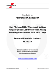
www.fairchildsemi.com User Guide for FEBFL7730_L20H008B Dimmable LED Bulb at High Line Featured Fairchild Product: FL7730 Direct questions or comments about this evaluation board to: “Worldwide Direct Support” Fairchild Semiconductor.com © 2012 Fairchild Semiconductor Corporation 1 FEBFL7730_L20H008B • Rev. 1.1.0 www.fairchildsemi.com Table of Contents 1. Introduction ............................................................................................................................... 3 1.1. General Description of FL7730........................................................................................ 3 1.2. Features of FL7730 .......................................................................................................... 3 1.3. Internal Block Diagram of FL7730 .................................................................................. 4 2. General Specifications for Evaluation Board ........................................................................... 5 3. Photographs............................................................................................................................... 6 4. Printed Circuit Board ................................................................................................................ 7 5. Schematic of the Evaluation Board........................................................................................... 8 6. Bill of Materials ........................................................................................................................ 9 7. Transformer Design ................................................................................................................ 11 8. Performance of Evaluation Board ........................................................................................... 12 8.1. Startup ............................................................................................................................ 12 8.2. Operation Waveforms .................................................................................................... 13 8.3. Constant Current Regulation .......................................................................................... 14 8.4. Open/Short LED Protections .......................................................................................... 15 8.5. Dimming Operation........................................................................................................ 16 8.6. System Efficiency .......................................................................................................... 19 8.7. Power Factor and THD .................................................................................................. 20 8.8. Operating Temperature .................................................................................................. 21 8.9. EMI................................................................................................................................. 22 9. Revision History ..................................................................................................................... 23 © 2012 Fairchild Semiconductor Corporation 2 FEBFL7730_L20H008B • Rev. 1.1.0 www.fairchildsemi.com This FEBFL7730_L20H008B Evalution Board can be identified by the silkscreen marking FL7730 High Line on the top side of the pcb. This user guide supports the evaluation board for the FL7730, FEBFL7730_L20H008B. This kit supersedes the FEBFL7730_L20H008A. The revised kit incorporates the next generation FL7730, which is redesigned for improved dimming performance. It should be used in conjunction with the FL7730 datasheet as well as Fairchild’s application notes and technical support team. Please visit Fairchild’s website at www.fairchildsemi.com or the evaluation board page http://www.fairchildsemi.com/products/evaluationboards/. 1. Introduction This document describes the proposed solution for low line voltage LED ballast using the FL7730 Primary Side Regulator (PSR) single-stage controller. The input voltage range is 180 VRMS – 265 VRMS and there is one DC output with a constant current of 380 mA at 22 Vout. This document contains general description of FL7730, the power supply specification, schematic, bill of materials, and the typical operating characteristics. 1.1. General Description of FL7730 The FL7730 is an active Power Factor Correction (PFC) controller using single-stage flyback topology. Dimming control with no flicker is implemented by analog sensing method. Primary-side regulation and single-stage topology minimize cost and reduce external components, such as input bulk capacitor and feedback circuitry. To improve power factor and THD, constant on-time control is utilized with internal error amplifier and low bandwidth compensator. Precise constant-current control regulates accurate output current, independent of input voltage and output voltage. Operating frequency is proportionally changed by output voltage to guarantee DCM operation with higher efficiency and simpler designs. FL7730 provides protections such as open-LED, shortLED, and over-temperature protection. 1.2. Features of FL7730 Compatible with Traditional TRIAC Control Cost-Effective Solution without Input Bulk Capacitor and Feedback Circuitry Power Factor Correction (PFC) Accurate Constant-Current (CC) Control Line Voltage Compensation for CC Control Linear Frequency Control for Better Efficiency and Simpler Design Open-LED Protection Short-LED Protection Cycle-by-Cycle Current Limiting Over-Temperature Protection with Auto Restart Low Startup Current: 20μA Low Operating Current: 5mA Frequency Hopping for EMI VDD Under-Voltage Lockout (UVLO) Gate Output Maximum Voltage Clamped at 18 V SOP-8 Package Available © 2012 Fairchild Semiconductor Corporation 3 FEBFL7730_L20H008B • Rev. 1.1.0 www.fairchildsemi.com 1.3. Block Diagram - + + Figure 1. © 2012 Fairchild Semiconductor Corporation Internal Block Diagram of FL7730 4 FEBFL7730_L20H008B • Rev. 1.1.0 www.fairchildsemi.com 2. General Specifications for Evaluation Board All data was measured with the board was enclosed in a case and external temperature of approximately 25°C. Table 1. Evaluation Board Specifications for LED Lighting Bulb Description Value Comments FL7730 Control IC of single-stage PSR TRIAC dimming 180 V 265 V 220~230 V 50~60 Hz Minimum input voltage Maximum input voltage Nominal input voltage Line frequency 10 V 28 V 22 V 380 mA ±65 mA < ±1.9% < ±3.1% Minimum output voltage Maximum output voltage Nominal output voltage Nominal output current Output current ripple Line input voltage change: 180~265 VAC Output voltage change: 10~28 V Eff180VAC Eff220VAC Eff230VAC Eff265VAC 84.5% 84.4% 84.4% 83.8% No dimmer connected Efficiency at 180 VAC line input voltage Efficiency at 220 VAC line input voltage Efficiency at 230 VAC line input voltage Efficiency at 265 VAC line input voltage PF/THD180VAC PF/THD 220VAC PF/THD 230VAC PF/THD 265VAC 0.97 / 13.7% 0.93 / 16.6% 0.92 / 17.3% 0.87 / 19.7% No dimmer connected PF/THD at 180 VAC line input voltage PF/THD at 220 VAC line input voltage PF/THD at 230 VAC line input voltage PF/THD at 265 VAC line input voltage TFL7730 TMOSFET TDIODE 46ºC 53ºC 45ºC 48ºC 49ºC 55ºC Open frame condition (Room temp. = 25ºC) FL7730 temperature Primary MOSFET temperature Secondary diode temperature Transformer temperature Active damper temperature Startup resistor temperature Symbol Fairchild Device Input Voltage Frequency VIN.MIN VIN.MAX VIN.NOMINAL FIN Output Voltage Current VOUT.MIN VOUT.MAX VOUT.NOMINAL IOUT.NOMINAL IOUT.RIPPLE CC deviation Efficiency PF/THD Temperature FL7730 Primary MOSFET Secondary Diode Transformer Active Damper Startup Resistor TTRNASFORMER TDAMPER TSTR.RESISTOR © 2012 Fairchild Semiconductor Corporation 5 FEBFL7730_L20H008B • Rev. 1.1.0 www.fairchildsemi.com 3. Photographs Figure 2. Top View of Board Figure 3. Bottom View of Board Dimensions: 62.5 mm (L) × 26.8 mm (W) × 12.0 mm (H) Figure 4. Side View in Bulb Case Type 1 Figure 5. Bottom View in Bulb Case Type 1 Bulb Case Type 1: 32 mm (Case Diameter) × 40 mm (Case Depth) Figure 6. Side View in Bulb Case Type 2 Figure 7. Bottom View in Bulb Case Type 2 Bulb Case Type 2: 34 mm (Case Diameter) × 44 mm (Case Depth) © 2012 Fairchild Semiconductor Corporation 6 FEBFL7730_L20H008B • Rev. 1.1.0 www.fairchildsemi.com 4. Printed Circuit Board Figure 8. Figure 9. © 2012 Fairchild Semiconductor Corporation Top Pattern of Board Bottom Pattern of Board 7 FEBFL7730_L20H008B • Rev. 1.1.0 www.fairchildsemi.com 5. Schematic of the Evaluation Board Figure 10. © 2012 Fairchild Semiconductor Corporation FL7730 Schematic 8 FEBFL7730_L20H008B • Rev. 1.1.0 www.fairchildsemi.com 6. Bill of Materials Item Part Reference No. Part Number Qty. Description Manufacturer 1 Q1 MB8S 1 Bridge Diode Fairchild Semiconductor 2 Q2 FQN1N50C 1 1 A / 500 V Active Damper MOSFET Fairchild Semiconductor 3 Q3 FL7730MY_F116 1 Main Controller Fairchild Semiconductor 4 Q4 FQU2N60C 1 2 A / 600 V Main Switch Fairchild Semiconductor 5 F1 SS-5-1A 1 1 A / 250 V Fuse Bussmann 6 L1 R06103KT00 2 10 mH Filter Inductor Bosung 7 L2 R06472KT00 2 4.7 mH Filter Inductor Bosung 8 D1 ES1J 1 1 A / 600 V Diode Fairchild Semiconductor 9 D2 1N5241 1 11 V Zener Diode Fairchild Semiconductor 10 D3 1N4003 1 1 A / 200 V Diode Fairchild Semiconductor 11 D4 RS1M 1 1 A / 1000 V Diode Fairchild Semiconductor 12 D5 ES3D 1 3 A / 200 V Fast Rectifier Fairchild Semiconductor 13 C1, C2 MPE 400V104K 14S 1 100 nF / 400 V Film Capacitor Sungho 14 C3 C0805C104K3RACTU 1 100 nF / 25 V SMD Capacitor 2012 Kemet 15 C4 C1206C105K3PACTU 1 1 µF / 25 V SMD Capacitor 3216 Kemet 16 C5 C0805C100M3GACTU 1 10 pF / 25 V SMD Capacitor 2012 Kemet 17 C6 C2012Y5V1E225Z 1 2.2 µF / 25 V SMD Capacitor 2012 TDK 18 C7 KMG 47 µF / 35 V 1 47 µF / 35 V Electrolytic Capacitor Samyoung 19 C8 C1206C103KDRACTU 1 10 nF / 1 kV SMD Capacitor 3216 Kemet 20 C9 SCFz2E472M10BW 1 4.7 nF / 250 V Y-Capacitor Samwha 21 C10 KMG 330 µF / 35 V 1 330 µF / 35 V Electrolytic Capacitor Samyoung 22 C11 RM 1000 µF / 35 V 1 1000 µF / 35 V Electrolytic Capacitor Samwha 23 R1 SFR2500001001FR500 1 1k Ω / 0.5 W Metal Resistor Vishay 24 R2 RNF12JTD300R 1 300 Ω / 0.5 W Metal Resistor Stackpole Electrical 25 R3 RC1206JR-0743KL 1 43 kΩ SMD Resistor 3216 Yageo 26 R4 RC1206JR-071ML 1 1 MΩ SMD Resistor 3216 Yageo 27 R5 RC0805JR-07510KL 1 510 kΩ SMD Resistor 2012 Yageo 28 R6 RC0805JR-07200KL 1 200 kΩ SMD Resistor 2012 Yageo 29 R7 RC0805JR-070R0L 1 0 Ω SMD Resistor 2012 Yageo 30 R8 RC0805JR-07150KL 1 150 kΩ SMD Resistor 2012 Yageo 31 R9 RC0805JR-0720KL 1 20 kΩ SMD Resistor 2012 Yageo 32 R10 RNF12GTD250K 1 250 kΩ / 0.5W Metal Resistor Stackpole Electrical 33 R11, R12 RC1206JR-07510KL 2 510 kΩ SMD Resistor 3216 Yageo 34 R13 RC0805JR-0710RL 1 10 Ω SMD Resistor 2012 Yageo © 2012 Fairchild Semiconductor Corporation 9 FEBFL7730_L20H008B • Rev. 1.1.0 www.fairchildsemi.com Bill of Materials (Continued) Item No. Part Reference Part Number Qty. Description Manufacturer 35 R14 RC1206JR-071R2L 1 1.2 Ω SMD Resistor 3216 Yageo 36 R15 RC1206FR-071RL 1 1.0 Ω SMD Resistor 3216 Yageo 37 R16 RC0805JR-070RL 1 0 Ω SMD Resistor 2012 Yageo 38 R17 RC1206JR-0751KL 1 51 kΩ SMD Resistor 3216 Yageo © 2012 Fairchild Semiconductor Corporation 10 FEBFL7730_L20H008B • Rev. 1.1.0 www.fairchildsemi.com 7. Transformer Design Figure 11. Transformer Bobbin Structure and Pin Configuration Figure 12. Table 2. Transformer Winding Structure Winding Specifications No Winding Pin (S → F) Wire Turns Winding Method 1 NP1 53 0.13φ 38 Ts Solenoid Winding 2 3 Insulation: Polyester Tape t = 0.025 mm, 2 Layers NS 4 5 NA 24 Ts Solenoid Winding 26 0.13φ 18 Ts Solenoid Winding Insulation: Polyester Tape t = 0.025 mm, 2 Layers NP2 8 Table 3. 0.3φ (TIW) Insulation: Polyester Tape t = 0.025 mm, 2 Layers 6 7 NS- NS+ 34 0.13φ 38 Ts Solenoid Winding Insulation: Polyester Tape t = 0.025 mm, 6 Layers Electrical Characteristics Pin Specification Remark Inductance 1– 2 1 mH ±10% 50 kHz, 1 V Leakage 1– 2 8 µH 50 kHz, 1 V Short all output pins © 2012 Fairchild Semiconductor Corporation 11 FEBFL7730_L20H008B • Rev. 1.1.0 www.fairchildsemi.com 8. Performance of Evaluation Board 8.1. Startup Startup time is 0.7 s. There is no overshoot at output current and voltage in startup sequence. (Refer IOUT and VDD waveform: VDD indicates a reflected output voltage.) Figure 13. Startup – VIN[220VAC] C1[VIN] C2[VCS] C3[VDD] C4[IOUT] (No Dimmer Connected) © 2012 Fairchild Semiconductor Corporation 12 FEBFL7730_L20H008B • Rev. 1.1.0 www.fairchildsemi.com 8.2. Operation Waveforms In steady state, line compensation regulates output current regardless of input voltage variations. Output current ripple is ±65 mA with a rated output current of 380 mA. VIN = 180 VAC VIN = 220 VAC VIN = 230 VAC VIN = 265 VAC Figure 14. Operation Waveforms – VO[22V] IO[380mA] C1[VCS] C3[VIN] C4[IOUT] © 2012 Fairchild Semiconductor Corporation 13 FEBFL7730_L20H008B • Rev. 1.1.0 www.fairchildsemi.com 8.3. Constant Current Regulation Constant current deviation in the wide output voltage range from 10 V to 28 V is less than 3.1% at each line input voltage. Line regulation at the rated output voltage (22 V) is less than 1.7% 35 30 OVP 25 VOUT [V] 20 180Vac 220Vac 230Vac 265Vac 15 10 5 0 0 100 200 300 400 500 Output Current [mA] Figure 15. Constant Current Regulation – Measured by E-Load [CR Mode] Table 4. Constant Current Regulation by Output Voltage Change (10~28 V) Input Voltage Min. Current Max. Current Tolerance 180 VAC / 60 Hz 385 mA 399 mA ±1.8% 220 VAC / 60 Hz 383 mA 398 mA ±1.9% 230 VAC / 60 Hz 382 mA 399 mA ±2.2% 265 VAC / 60 Hz 374 mA 398 mA ±3.1% Table 5. Constant Current Regulation by Line Voltage Change (180~265 VAC) Output Voltage 180 VAC 220 VAC 230 VAC 265 VAC Tolerance 20 V 392 mA 388 mA 387 mA 377 mA ±1.9% 22 V 390 mA 387 mA 384 mA 377 mA ±1.7% 24 V 386 mA 383 mA 382 mA 375 mA ±1.4% © 2012 Fairchild Semiconductor Corporation 14 FEBFL7730_L20H008B • Rev. 1.1.0 www.fairchildsemi.com 8.4. Open-LED and Short-LED Protections In short-LED condition, the OCP level is reduced from 0.7 V to 0.2 V because the FL7730 lowers the OCP level when the VS voltage is less than 0.4 V during output diode conduction time. The output current in the short-LED condition is less than 1.5 A, which doesn’t damage external components. Figure 16. Short-LED Condition – VIN[220 VAC] C1[VCS] C2[VDD] C3[VIN] C4[IOUT] In open-LED condition, output voltage is limited around 32 V by OVP in VDD. The output over-voltage protection level can be controlled by the turn ratio of the auxiliary and secondary windings. Figure 17. © 2012 Fairchild Semiconductor Corporation Open-LED Condition – VIN[220 VAC] C1[VCS] C2[VDD] C3[VIN] 15 FEBFL7730_L20H008B • Rev. 1.1.0 www.fairchildsemi.com 8.5. Dimming Operation Dimming operation waveforms are shown in Figure 18 through Figure 21. Active damper, RC bleeder, and dimming control in FL7730 implement flicker-free dimming oepration. Spike current at dimmer firing is less than 1 A. Figure 18. Figure 19. Dimming Operation Waveforms – Max. Dimming Angle, VIN[220 VAC] C1[VIN] C2[VCS] C4[IIN] Dimming Operation Waveforms – 90º Dimming Angle, VIN[220 VAC] C1[VIN] C2[VCS] C4[IIN] © 2012 Fairchild Semiconductor Corporation 16 FEBFL7730_L20H008B • Rev. 1.1.0 www.fairchildsemi.com Figure 20. Dimming Operation Waveforms – Min. Dimming Angle, VIN[220 VAC] C1[VIN] C2[VCS] C4[IIN] Output current is controlled by the dimming function when rotating dimmer switch as below dimming curve. The dimming control block in the FL7730 smoothly changes regulated output current by detecting dimming angle. Figure 21. Dimming Curve (Effective RMS Input Voltage vs. Output Current) – Line Voltage[220 VAC] © 2012 Fairchild Semiconductor Corporation 17 FEBFL7730_L20H008B • Rev. 1.1.0 www.fairchildsemi.com Table 6. Dimmer Compatibility Manufacturer Dimmer Condition Max Current Min Current Flicker NANO SKD-500 220 V / 60Hz 365 mA 24 mA (7%) No JIN HEUNG SA04003 220 V / 60Hz 364 mA 53 mA (15%) No ANAM D-500 220 V / 60Hz 350 mA 58 mA (17%) No OPPLE P068102 220 V / 60Hz 378 mA 6 mA (2%) No DAESUNG SKD-500 220 V / 60Hz 366 mA 6 mA (2%) No GIRA 226200 230 V / 50Hz 319 mA 64 mA (20%) No GIRA 30000 230 V / 50Hz 335 mA 80 mA (24%) No JUNG 225NVDE 230 V / 50Hz 320 mA 70 mA (22%) No JUNG ST550 230 V / 50Hz 325 mA 100 mA (31%) No JUNG 266GDE 230 V / 50Hz 332 mA 61 mA (18%) No KOPP 8033 230 V / 50Hz 300 mA 100 mA (33%) No BUSCH 2200 230 V / 50Hz 338 mA 66 mA (20%) No BUSCH 2247U 230 V / 50Hz 323 mA 108 mA (33%) No BUSCH 2250 230 V / 50Hz 335 mA 60 mA (18%) No MERTEN 5721 230 V / 50Hz 365 mA 30 mA (8%) No PEHA 436 230 V / 50Hz 306 mA 120 mA (40%) No EVERFLORISH EF700DC [Trailing] 230 V / 50Hz 327 mA 154 mA (47%) No MERTEN 577129 [Trailing] 230 V / 50Hz 330 mA 147 mA (44%) No BUSCH 6513 [Trailing] 230 V / 50Hz 353 mA 145 mA (41%) No The FL7730 high-line board shows good dimmer compatibility without flicker. To reduce the minimum LED current, follow the below design guide: Reduce DIM resistors (R5 and R6) to decrease minimum DIM voltage. (DIM offset voltage by DIM internal current source (7.5 μA) is reduced by smaller R6.) Increase the bleeder capacitor (C1). (When reducing minimum LED current, bleeder current should be larger to stabilize input current without flicker. However, increasing C1 reducees PF. This is always trade-off of “flicker-free design vs. PF” in RC bleeder structure.) © 2012 Fairchild Semiconductor Corporation 18 FEBFL7730_L20H008B • Rev. 1.1.0 www.fairchildsemi.com 8.6. System Efficiency Power efficiency is 83.8 ~ 84.5% in 180 ~ 265 VAC input voltage range. 90 88 86 84 82 Eff. [%] 80 78 76 74 72 70 180Vac 220Vac 230Vac 265Vac Input Voltage [V] Figure 22. Table 7. Power Efficiency (Input voltage vs. Efficiency) System Efficiency Input Voltage Input Power Output Current Output Voltage Output Power Efficiency 180 VAC 10.13 W 392 mA 21.84 V 8.56 W 84.5% 220 VAC 9.97 W 386 mA 21.80 V 8.41 W 84.4% 230 VAC 9.94 W 385 mA 21.79 V 8.39 W 84.4% 265 VAC 9.76 W 376 mA 21.75 V 8.18 W 83.8% © 2012 Fairchild Semiconductor Corporation 19 FEBFL7730_L20H008B • Rev. 1.1.0 www.fairchildsemi.com 8.7. Power Factor and Total Harmonic Distortion (THD) The FL7730 shows excellent power factor and THD performance. Power factor is over 0.9 at 180~230 VAC. THD is less than 30% of the specification. PF Input Voltage Figure 23. PF PF & THD (50 Hz) Input Voltage Figure 24. Table 8. THD THD PF & THD (60 Hz) Power Factor and THD Input Voltage Output Current Output Voltage 180 VAC 392 mA 21.84 V 220 VAC 386 mA 21.80 V 230 VAC 385 mA 21.79 V 265 VAC 376 mA 21.75 V © 2012 Fairchild Semiconductor Corporation 20 Frequency PF THD 50 Hz 0.97 14.0% 60 Hz 0.97 13.7% 50 Hz 0.94 16.7% 60 Hz 0.93 16.6% 50 Hz 0.93 17.4% 60 Hz 0.92 17.3% 50 Hz 0.88 19.9% 60 Hz 0.87 19.7% FEBFL7730_L20H008B • Rev. 1.1.0 www.fairchildsemi.com 8.8. Operating Temperature Temperature of the all components on this board is less than 55ºC. Figure 25. Figure 26. © 2012 Fairchild Semiconductor Corporation Board Temperature - Top View, VIN[220 VAC] IO[380 mA] Board Temperature - Bottom View, VIN[220 VAC] IO[380 mA] 21 FEBFL7730_L20H008B • Rev. 1.1.0 www.fairchildsemi.com 8.9. EMI The all measurement was conducted in observance of CISPR22 criteria. Figure 27. © 2012 Fairchild Semiconductor Corporation EMI Results – VIN[220 VAC] VOUT[22 V], IOUT[380 mA] 22 FEBFL7730_L20H008B • Rev. 1.1.0 www.fairchildsemi.com 9. Revision History Rev. Date 1.0.0. Oct. 2011. Initial Release Aug. 2012. Manufacturer & Part number are added in BOM FL7730 is changed to FL7730MY_F116 (no frequency hopping) Dimmer compatibility table is updated PF/THD at 50Hz is added EMI test result is updated Updating to match new naming conventions 1.1.0 Description WARNING AND DISCLAIMER Replace components on the Evaluation Board only with those parts shown on the parts list (or Bill of Materials) in the Users’ Guide. Contact an authorized Fairchild representative with any questions. The Evaluation board (or kit) is for demonstration purposes only and neither the Board nor this User’s Guide constitute a sales contract or create any kind of warranty, whether express or implied, as to the applications or products involved. Fairchild warrantees that its products meet Fairchild’s published specifications, but does not guarantee that its products work in any specific application. Fairchild reserves the right to make changes without notice to any products described herein to improve reliability, function, or design. Either the applicable sales contract signed by Fairchild and Buyer or, if no contract exists, Fairchild’s standard Terms and Conditions on the back of Fairchild invoices, govern the terms of sale of the products described herein. DISCLAIMER FAIRCHILD SEMICONDUCTOR RESERVES THE RIGHT TO MAKE CHANGES WITHOUT FURTHER NOTICE TO ANY PRODUCTS HEREIN TO IMPROVE RELIABILITY, FUNCTION, OR DESIGN. FAIRCHILD DOES NOT ASSUME ANY LIABILITY ARISING OUT OF THE APPLICATION OR USE OF ANY PRODUCT OR CIRCUIT DESCRIBED HEREIN; NEITHER DOES IT CONVEY ANY LICENSE UNDER ITS PATENT RIGHTS, NOR THE RIGHTS OF OTHERS. LIFE SUPPORT POLICY FAIRCHILD’S PRODUCTS ARE NOT AUTHORIZED FOR USE AS CRITICAL COMPONENTS IN LIFE SUPPORT DEVICES OR SYSTEMS WITHOUT THE EXPRESS WRITTEN APPROVAL OF THE PRESIDENT OF FAIRCHILD SEMICONDUCTOR CORPORATION. As used herein: 1. Life support devices or systems are devices or systems which, (a) are intended for surgical implant into the body, or (b) support or sustain life, or (c) whose failure to perform when properly used in accordance with instructions for use provided in the labeling, can be reasonably expected to result in significant injury to the user. 2. A critical component is any component of a life support device or system whose failure to perform can be reasonably expected to cause the failure of the life support device or system, or to affect its safety or effectiveness. ANTI-COUNTERFEITING POLICY Fairchild Semiconductor Corporation's Anti-Counterfeiting Policy. Fairchild's Anti-Counterfeiting Policy is also stated on our external website, www.fairchildsemi.com, under Sales Support. Counterfeiting of semiconductor parts is a growing problem in the industry. All manufacturers of semiconductor products are experiencing counterfeiting of their parts. Customers who inadvertently purchase counterfeit parts experience many problems such as loss of brand reputation, substandard performance, failed applications, and increased cost of production and manufacturing delays. Fairchild is taking strong measures to protect ourselves and our customers from the proliferation of counterfeit parts. Fairchild strongly encourages customers to purchase Fairchild parts either directly from Fairchild or from Authorized Fairchild Distributors who are listed by country on our web page cited above. Products customers buy either from Fairchild directly or from Authorized Fairchild Distributors are genuine parts, have full traceability, meet Fairchild's quality standards for handling and storage and provide access to Fairchild's full range of up-to-date technical and product information. Fairchild and our Authorized Distributors will stand behind all warranties and will appropriately address any warranty issues that may arise. Fairchild will not provide any warranty coverage or other assistance for parts bought from Unauthorized Sources. Fairchild is committed to combat this global problem and encourage our customers to do their part in stopping this practice by buying direct or from authorized distributors. © 2012 Fairchild Semiconductor Corporation 23 FEBFL7730_L20H008B • Rev. 1.1.0