1
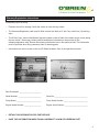
OWNER & OPERATORS
MANUAL
HYDROJETTERS™
Hydrojetter™ Model: 7040-SC
Serial Number: OBM-XXXX
Provide the above numbers to Hi-Vac when ordering parts
Phone: (740) 374-2306
Toll Free: (800) 638-1901
e-mail: [email protected]
www.obrienmfg.com
We appreciate your business and would like to Thank You for your
recent purchase of an O’Brien Hydrojetter.
Your unit is built with QUALITY and is built to pass the test of time.
Please refer to the manuals included with your O’Brien regarding
the maintenance and care of the pump, engine and unit.
It is important that you return the Warranty Registration Card that
is included with your owner’s manual. Filling out and returning the
Warranty Registration Card to Hi-Vac Corp. will enable you to begin
your service contract.
Once again, thank you for your purchase. If you should have other
sewer equipment needs in the future, we hope that you will
continue to depend on Hi-Vac Corp.
Please call Hi-Vac Corporation’s Technical Service department with
your service or operation questions. Toll Free phone number
(800) 638-1901.
To find out more about our quality products, visit our web site at
www.obrienmfg.com.
1
Company Overview & General Sewer Cleaning Information
Your new O’Brien unit is the latest model developed in over 50 years of producing sewer cleaning equipment.
Depending on your pump, over 2,500 psi water pressure can be generated. This pressure is directed through
the hose to a nozzle, which is propelled into the sewer line by a rearward directed force of water. Just the right
amount of water plus pressure is needed to effectively clean the pipe and neither high pressure nor large
amounts of water alone will do the job.
With just the right combination at your disposal, you will find the jet nozzle will carry the weight of the hose
into the pipe. With the penetrator installed (we recommend that your cleaning begin with the penetrator
nozzle) it should penetrate most blockages of grease, sand, mud etc. that clog the line.
Normally, the penetrator nozzle is used to scour the inside of the pipe. The actual cleaning of the pipe is done
as the hose is being retracted from the pipe onto the reel. You will note that this brings out the source of the
blockage. Little or no cleaning is done while entering the sewer either with the penetrator or other nozzles.
Therefore it is very important that when retracting the hose a slow steady speed is used. Many times it is
necessary to repeat this slow retracting process to thoroughly clean the pipe.
Hi-Vac’s years of experience in developing and using various pressures and flows has not succeeded in being
able to cut roots by pressure alone. Although some manufacturers state that extremely high pressure will
remove roots, Hi-Vac has not been able to confirm or verify these statements. Instead, Hi-Vac offers the
patented original water powered root cutter unit.
When any root systems are encountered, we highly recommend the O’Brien Root Cutter machine, which not
only cuts any roots in the system but other blockages such as starch and grease build-ups. The Root Cutter
also is an aid in indicating broken or caved-in tile pipe or sewers.
Before operating the unit read the enclosed engine and pump manuals carefully and review the safety
information in great detail.
2
TABLE OF CONTENTS
Warranty Registration Instructions
Warranty
Warranty Information
Warranty Frequently Asked Qusetions (FAQ)
Towing Instructions
Pump and Pressure System
High Pressure Hydrojetting
Hydrojet Tank Filling
Engine Operating Procedure
Setting Up For Operation
Hydraulic/Electric Operation Instructions
Operating Instructions
Hydrojetter Operation Safety Procedures
Warnings
Pipe Jetting Procedures
When Obstructions are Encountered
Pulsation
Wash Down Gun
Cold Weather Protection/Winterization of Hydrojetter
Lubrication and General Maintenance
Troubleshooting
Troubleshooting Checklist
Suggested Training Outline
How To Use The Parts & Accessories Manual
Special Note
Water Pump Important Information
3
Warranty Registration Instructions
Immediately upon receiving:
•
Examine the unit for damage. Notify the carrier at once with any claims.
•
The Warranty/Registration card must be filled out and mail back to Hi-Vac Corp. within ten (10) working
days. The Hi-Vac Corp. vehicle identification tags are located on the left side of the trailer tongue, when facing
the tow vehicle. These tags contain product identification information to be provided on the warranty/registration card. Record the following information here in the space provide. This information
must be provided when filing a warranty claim or ordering parts.
Information can also be found on the Unit ID Sheet located in front of the operations manual.
•
•
Date Purchased: ______________________
Model Number: _______________________
Serial No: _________________________________
Pump Model: _________________________
Pump Serial Number: ________________________
Engine Model Number: _________________
Engine Serial Number: _______________________
•
RETAIN THIS INFORMATION FOR FURTHER USE
•
HAVE THIS INFORMATION WHEN FILING A WARRANTY CLAIM OR ORDERING PART
4
Warranty
Each and every product manufactured by Hi-Vac Corp. is tested carefully prior to shipment to assure a high
standard of quality and maximum operating efficiency. The following warranty is operative upon the receipt, by
Hi-Vac Corp., of a properly completed and executed warranty registration card.
A.
Hi-Vac warrants that trailer mounted sewer units, equipment, accessories and parts
manufactured by Hi-Vac shall for a period of one (1) year from date of purchase be free from:
1. Defects in material and workmanship.
2. Defects arising from process of manufacturing.
3. Defects in design thereof.
B. The foregoing warranty shall not apply to components supplied to Hi-Vac Corp. by other
manufacturers. The purchaser is directed to contact said individual manufacturers nearest
factory service center for repair or replacement of said components. Hi-Vac Corp., when
necessary, will act as agent to secure adjustment. Purchaser is responsible for labor and freight of any return part/components.
C. In case of defects in material or workmanship or defects arising from processes of manufacture or design, such defects must become apparent in the machine, accessory, equipment, or part within (1) year from date of purchase. The extent of Hi-Vac Corp.’s liability under the warranty is limited to the repair of such defects or to the repair or replacement of any part, equipment, or accessory, which is defective in any such respects.
D.
Hi-Vac Corp. shall, as to each defect, be relieved of all obligations and liability under this
warranty if:
1. The product is operated with any accessory, equipment, or part not specifically
approved by Hi-Vac Corp. and not manufactured by Hi-Vac Corp. unless
purchaser furnishes reasonable evidence that such installation was not the case of the defect.
2. The product is not operated or maintained in accordance with Hi-Vac’s operation manual furnished with said equipment.
3. The product was modified, altered, or repaired without the approval of Hi-Vac
Corp.
4. The purchaser does not, within the applicable time period set forth in paragraphs
A and C above; notify Hi-Vac Corp. of said defect. Disassembly of the product to correct the defect, removal of the defective accessory, new part(s)and reassembly of the product shall be at the purchaser’s expense.
5. Purchaser does not submit reasonable proof that the defect is due to a material
embraced within Hi-Vac Corp.’s warranty hereunder.
Liability under this warranty is limited to parts and is furthermore limited to the replacement or repair of said
parts returned, freight prepaid, to Hi-Vac Corp. Only parts deemed defective due to workmanship or a related
defect will be warranted. An Authorization To Return (ATR) number and completed warranty evaluation form
are required prior to the return of any part(s) to Hi-Vac. Under no circumstances is loss of time, revenue, or
consequential damages covered
under this warranty.
Any part(s) returned without proper pre-authorization will be returned/refused. Technical service will
supply the ATR. Please phone Technical Service @ (800) 638-1901 to obtain the proper authorization or
with any other service related question.
5
Warranty Information
ENGINES
CLUTCHES
PUMPS
AXLES, LIGHTS & HITCHES
HOSES & HOSE REELS
There are several items on your equipment that are warranted by the original manufacturer. If warranty is
needed, these items often require a certified technician at a local service center. The following directory is
provided so that if you need assistance you may call and locate the nearest technician and service center to
your location.
All clutches are installed and warranted by the engine manufacturer. Please contact the applicable engine
manufacturer for a local service center if you have a clutch for warranty consideration.
Engines John Deere (330) 239-2242 Kubota (740) 964-0089
Honda (800) 626-7326
Cummins (614)527-2832
Clutches
North American Clutch (800) 383-9204
Pumps Giant (800) 633-4565 FEMyers (419) 281-9239
General (888) 474-5487
Axles, Lights & Hitches
Red Neck Trailer (309) 862-1000
Hoses & Hose Reels
Piranha (800) 250-5132
Parker Dayco (330) 296-1433
Poly-Flo (503) 493-0015
CoxReels (800) 269-7335
Hose-Trac (888) 489-8828
Reel Craft (800) 444-3134
Hi-Vac Corporation’s Toll-Free Technical Service Number
(800) 638-1901
6
Warranty Frequently Asked Qoestions (FAQ)
Listed below are frequently asked questions about our warranty. This summary does not constitute a warranty. For full
warranty details, refer to your official warranty supplied with your unit.
Question:
What is covered and for how long?
Answer:
Your O’Brien Hydrojetter is covered under warranty for a period of one year (12 months) from date of purchase. Hi-Vac
Corp. bases the one year (12 month) warranty on the purchase invoice date. Only the original
purchaser of the unit is covered. The warranty is non- transferable. Warranty does not include replacement of unit or use
of spare unit under any circumstance.
Question:
What about the pump, engine or other parts not manufactured by Hi-Vac Corp. on my unit, what do I do about
warranty on those items?
Answer:
There are several items on your unit that are warranted by the original manufacturer. If warranty is needed, these items
often require a certified technician at a local service center. All clutches are installed and warranted by the engine manufacturer. Please contact the applicable engine manufacturer for your local service center if you have a clutch for warranty
consideration. You may refer to the list on page 4 for a phone number to call for local service in your area.
Question:
What about my ‘down time’ if my engine or pump needs repairs– what will you compensate me for this?
Answer:
Hi-Vac Corporation will assist customers in receiving the assistance they need with engine, pump or other manufacturers,
however, Hi-Vac Corp. does not compensate for down time.
Question:
How do I return a part for warranty consideration?
Answer:
Contact Technical Service – (800) 638-1901 to obtain a Authorization To Return (ATR) number. This number will be coded
on your customer information and you will be asked to write this number on your shipping box.
Question:
When do I receive my credit?
Answer:
All parts returned with an ATR number are evaluated, upon receipt. Hi-Vac Corporation, in many cases, will have to return
the part to a vendor for evaluation and/or credit. Upon the final disposition of the part, you will be notified as to the result. If
credit is to be issued, you will receive credit on your account to be used towards future purchases.
Question:
Can you send a call-tag for my part?
Answer:
Hi-Vac Corporation does not issue call-tags for return of merchandise. The customer may send Hi-Vac the part(s) – via
UPS, US Mail or freight company with the ATR# clearly visible on the outside of the package.
Question:
Will you send a technician to repair my unit under warranty?
Answer:
Hi-Vac Corporation strives for customer satisfaction and has a nation-wide network of Dealers/Distributors and Service
Companies to contact. Hi-Vac will be happy to assist you with your service needs; however, we do not regularly send our
technicians on service calls.
7
Towing Instructions
Trailer Hitch
Check rating of vehicles trailer hitch - Class IV - 6,000 lbs., 7,000 lbs., & 12,000 lbs.
Towing capacity
Vehicle GCWR (Gross Combined Weight Rating)
Towing capacity = GCWR minus vehicle weight minus cargo weight minus passenger weight.
Note: GCWR is provided on your vehicle or in your vehicle manual.
Vehicle Towing Capacity
Refer to your vehicle owners manual for listed trailer towing capacity.
Trailer towing capacity should equal GCWR (Gross Combined Weight Rating) minus vehicle weight minus
cargo weight minus passenger weight and (vehicle) fluids weight.
Wire the plug receptacle to your vehicle as shown below.
Note: The wire colors on the Hydrojet running lights are also indicated in Fig.1 for re-wiring to a
different plug design.
Always use trailer lights.
Fig. 1
8
9
Towing Instructions (cont.)
Towing
1. 2. 3. Position hitch coupler above trailer hitch ball.
Lower trailer tongue until ball rests in ball socket.
Be sure to lock the ball down then pin this with a safety bail pin.
CAUTION:
4. 5. Connect breakaway cable solidly to bumper or frame of tow vehicle as close to center as
possible. The cable must hang clear of trailer tongue and be long enough to permit short radius turns without pulling breakaway cable forward.
Make sure breakaway cable is in the released position with retaining pin in place.
CAUTION: Note: 6. Do not use breakaway switch as a parking brake, as this will run down the
battery on your jetter.
Check location of breakaway cable periodically during each trip. Accidental
application will cause brakes to drag and heat up, causing failure.
Cross safety chains under tongue and securely attach chains to bumper or frame of tow vehicle.
CAUTION: Safety chains must be used.
7. Fully retract hitch jack and remove caster wheel and/or skid plate. This will provide adequate ground clearance for transport.
8. Return high pressure reel to towing position or square with back of unit. Attach hose end to swivel fitting or recirculation system provided on back of trailer.
You are now ready to tow your O’Brien.
9. CAUTION: Note: Avoid sharp turns. This could bend, create extreme stress or fracture either the actuator or trailer tongue (if applicable).
Trailer is equipped with Electric or Surge Brakes.
2-5/16” Bulldog Hitch
Part #OBJ-1081TC
3” Pintel Hitch (Optional)
Part #OBJ-1081
10
Pump and Pressure System
The pump and relief valve are the heart of your O’Brien. They have been specially designed for use with cold
water (140°F max.) for pipe jetting, but can provide useful water flow for many other cleaning jobs using the
optional Washdown Gun and special attachments. The Triplex Ceramic Plunger Pump (each crankshaft
revolution has to move a certain amount of water) uses 3 plungers (similar to pistons in an engine) to create
water flow. Pressure is not created until the pump outlet is restricted with a valve or a nozzle. The pump,
valving and hose can support up to 4000 psi working pressure depending on model that you have.
The regulator valve acts to direct the water flow to the water tank when the hose reel and hand gun valves are
off or if nozzles provide too much restriction for total flow. Always use clean water to keep the regulator valve
operating properly. The hose and nozzle are designed to allow full flow and the Washdown Gun operates at up
to 1100 PSI max pressure. If leaks develop in the system between the relief valve and hose reel (or hand gun
valve) you will hear intermittent engine surges in the bypass, as the bypass pressure gradually drops and is
built up again by the pump. Tighten or otherwise repair the leaks for smooth running. Always stop engine and
release pressure before any plumbing changes or repairs.
Because of the inherent hazards with high pressure, use only Hi-Vac Corp. authorized high pressure hoses
and components when repairing your machine.
If nozzles become plugged, the regulator valve will direct some of the flow back to the water tank while
providing constant pressures. If pressure is seen with normal engine speed, check and clean the nozzles.
Reducing engine rpm will produce lower pressures to prevent the regulator valve from bypassing on and off.
11
High Pressure Hydrojetting
High Pressure Hydrojetting
High pressure Hydrojetting is the utilization of high pressure water combined with sufficient water flow to
Highdebris
pressure
Hydrojettingpipes.
is theHigh
utilization
of high
pressurecan
water
combined
sufficient
water
remove
in drain/sewer
pressure
Hydrojetting
also
be usedwith
to remove
debris
on flow to
remove
debris
in
drain/sewer
pipes.
High
pressure
Hydrojetting
can
also
be
used
to
remove
debris
on
surfaces.
surfaces.
A high pressure Hydrojetter consist of a pump, a motor or engine, a hose reel, a given length of hose and
A high pressure Hydrojetter consist of a pump, a motor or engine, a hose reel, a given length of hose and
various assortment of nozzles.
various assortment of nozzles.
A pipe
is cleaned
withwith
a high
pressure
Hydrojetter
by directing
water
pressure
andand
flowflow
through
a nozzle.
A pipe
is cleaned
a high
pressure
Hydrojetter
by directing
water
pressure
through
a nozzle.
Controlled
water
pressure
and
flow
propels
a
Hydrojetter
nozzle
through
the
sewer
pipe
allowing
it
to
Controlled water pressure and flow propels a Hydrojetter nozzle through the sewer pipe allowing it to
remove
andand
wash
away
thethe
obstruction.
remove
wash
away
obstruction.
Ideally,
a sewer
pipepipe
is cleaned
from
the the
lower
endend
of the
pipepipe
andand
thethe
hose
propels
itself
to the
higher
end
of of
Ideally,
a sewer
is cleaned
from
lower
of the
hose
propels
itself
to the
higher
end
the pipe
withwith
the help
of aof
nozzle.
By slowly
withdrawing
the Hydrojet
hose,hose,
the water
pressure
and and
flowflow
the pipe
the help
a nozzle.
By slowly
withdrawing
the Hydrojet
the water
pressure
cleans
the the
lineline
most
effectively.
When
it is impossible
to clean
fromfrom
the lower
end of
theofpipe,
the pipe
mustmust
cleans
most
effectively.
When
it is impossible
to clean
the lower
end
the pipe,
the pipe
be water
jetted
several
times
to remove
all all
thethe
debris.
A skilled
operator
can can
effectively
clean
a drain/sewer
be water
jetted
several
times
to remove
debris.
A skilled
operator
effectively
clean
a drain/sewer
regardless
of
the
obstacles
in
his/her
way.
regardless of the obstacles in his/her way.
How a Jet Works
(Penetrating Nozzle)
Nozzle to be used for initial
penetration of sewer pipe.
(Flushing Nozzle)
Nozzle to be used for thorough
cleaning of sewer pipe.
Fig. 2
Fig. 2
Hydrojet Tank Filling
Hydrojet Tank Filling
Fill the water tank from a clean water source. Always flush rust out of hydrants before connecting fill hose.
Hydrojetter
can betank
filled
using
a 5/8”water
garden
hose Always
on a fill flush
reel (optional)
using a fire
hydrant
fill (standard).
Fill the water
from
a clean
source.
rust out oforhydrants
before
connecting
fill hose.
FireHydrojetter
hydrant fill requires
Fill
Hose
(P/N
A176150).
can be filled using a 5/8” garden hose on a fill reel (optional) or using a fire hydrant fill
(standard). Fire hydrant fill requires Fill Hose (P/N A176150).
Important Note: If the next 4 items are not followed, cavitation of the pump could occur and reduce
operating efficiency and severely damage the pump.
Important Note: (If the next 4 items are not followed, cavitation of the pump could occur and reduce
•
Use water temperatures under
140°F.
operating
efficiency and severely damage the pump.
•
Ensure
that temperatures
both water strainers
are clean (check daily or as needed).
- Use water
under 140°F.
•
•
We install ball valve after strainer, so end user cannot starve pump.
- Ensure that both water strainers are clean (check daily or as needed).
- We install ball valve after strainer, so end user cannot starve pump.
- The pump drain valve must be closed.
The pump drain valve must be closed.
12
Engine Operating Procedures
Our O’Brien instrument control panels may have a Murphy Safety Gauge installed.
Start Up
•
•
Check water tank level. Our Hydrojetters may be equipped with a Low Water Shut-Off switch that will
prevent the engine from starting at low water levels. (Optional)
Check fuel level.
Note: Also Check engine and pump oil levels per manufacturer specifications.
•
•
•
•
Be sure fuel valve is ON (If applicable).
Turn high pressure reel supply “OFF” and disengage clutch (If applicable).
Turn key to “Preheating (Glow Plug)” position until Glow Lamp turns off on instrument panel (If
applicable).
Note: No warm up required if ambient temperature is above 50° F or when the engine is warmed up.
•
•
Hold in red relay button and turn key switch to crank position and start engine. (If applicable)
Allow engine to warm up for several minutes.
Engine Shut-Down
•
•
•
•
•
Idle engine down.
Disengage clutch and turn H.P. reel supply valve to “OFF” position (If applicable).
Allow engine to idle for 2 minutes.
Turn “OFF” key switch.
Turn the fuel valve OFF (If applicable).
13
evel. Our Hydrojetters may be equipped with a Low Water Shut-Off switch that will
e engine from starting at low water levels. (OPTIONAL)
engine and pump oil levels per manufacturer specifications.
s ON. (If Applicable)
reel supply “OFF” and disengage clutch, if applicable.
ating (Glow Plug)” position until Glow Lamp turns off on instrument panel, if applicable.
Setting
For Operation
required if
ambient Up
temperature
is above 50° F or when the engine is warmed up.
utton and turn key switch to crank position and start engine. (If Applicable)
rm up forAlways
severalposition
minutes.your Hydrojetter in the driest and safest place possible. Avoid high traffic areas and use
flashers and safety cones. Position the Hydrojetter so that the hose can be pulled directly off the hose reel for
use. Remember that jetting is most effective when you jet against the water flow. See Figure 3 for the
recommended positioning of your Hydrojetter for best visibility during manhole work. Note that loose hose and
damaging
corners
minimized
when
the Hydrojetter is parked as shown.
nd turn H.P.
reel supply
valveare
to “OFF”
position,
if applicable.
e for 2 minutes.
witch. When operating on unlevel ground, position trailer with the hitch (tank sump) end at the downhill side.
OFF, if applicable.
For non-manhole use, allow extra space for handling the hose before it is wound back on the hose reel or run
the hose directly to the pipe inlet using extra hose guards to protect the hose from cutting when going around
corners.
ation
Warning:
Do not unhitch or operate Hydrojetter unhitched upon unlevel ground.
When unhitching your Hydrojetter from the towing vehicle, always follow these steps:
• Disconnect ball hitch or pintle hitch by raising lever and jacking hitch up.
• Disconnect safety chains and light cord before driving away.
etter in the driest and safest place possible. Avoid high traffic areas and use flashers and
ydrojetter so that the hose can be pulled directly off the hose reel for use. Remember that
n you jet against the water flow. See Figure 3 for the recommended positioning of your
during manhole work. Note that loose hose and damaging corners are minimized when
hown.
round, position trailer with
he downhill side.
extra space for handling the hose
e hose reel or run the hose directly
ose guards to protect the hose from
orners.
If not able to park
over manhole, use
second tiger tail at
edge of manhole or
wherever hose is
dragged past a corner
or sharp edge.
Preferred Hydrojetter™
Position for visibility
Safety Cone
o not unhitch or operate Hydrojetter
pon unlevel ground.
ojetter from the towing vehicle,
tle hitch by raising lever and jacking
y chains and light cord before driving
Note: Use the tiger tail at cleanouts
or other access points even
when hose is pulled manually
as in mobile hose reel use.
main sewer hose
tigertail
Tie Rope
leader hose
work hose upstream
whenever possible
Normal Flow
13
Fig 3
Fig. 3
14
Hydraulic/Electric Operating Instructions
Reel hydraulic/electric can be used to feed off and to rewind hose on reel. Hose end should be secured to
recirculation system or swivel fitting while transporting your Hydrojetter™.
Reel is hydraulically/electronically locked from rotating in neutral (position between hose in and out). Move
hydraulic/electric control up to rewind hose on hose reel and down to power feed hose off hose reel.
The reel speed can be increased or decreased by adjusting the variable speed. Turn the variable speed control
knob out to increase speed or turn knob in to decrease speed.
Operating Instructions
1. Check the engine oil and hydraulic oil levels.
2. Fill tank while watching sight gauge so not to overfill. If filling from a fire hydrant, it is important to flush the hydrant to remove rust and corrosives from the lines before filling the tank. Although O’Brien provides polyethylene water tank(s) with strainer basket, rust and foreign matter could get from
the tank into the pump or valve, and damage the system. O’Brien machines come with a curbside fill location. This affords the operator protection from traffic when filling on busy thoroughfares. (Close main drain valve located at front right corner of tank) All locations are from a standing position facing back or instrument panel of machine.
3. When starting a cold gas engine, pull choke out and turn key clockwise (2010-JK,3510-E, 3510-FC).
When starting a diesel engine with a glow plug feature, turn key clockwise to the on position then push black button on panel for 20 seconds. If engine still does not start repeat. Turn key clockwise to
start engine (3515-FC). When starting a diesel engine with out the glow plug feature, turn key clockwise while holding red Murphy button in (3518-SC, 7030-SC, 7040-SC).
4. Engine should be started and warmed up for 3 to 5 minutes before applying any load.
5. Although your machine has the finest, toughest sewer-cleaning hose available, it is useful to protect the hose with a hose guide. Available and perhaps included with your machine is, an Upper Hose Guide, Lower Hose Guide, or a flexible Hose Guide (Tiger Tail), you may have other guides included with your machine and there may be other accessories available.
6. The hose reel must then be positioned over the manhole pipe to be cleaned.
7. Normal cleaning is started by using the penetrator nozzle, which should be attached at this time.
8. Before putting pressure to nozzle, unwind hose from the reel by using the reel control valve on the
operator’s panel. Care should be taken not to damage the hose by keeping it clear of the manhole sides.
9. Point of the hose nozzle should be pointed upstream into the pipe rather than downstream.
15
Operating Instructions (cont.)
10. Make sure water control valve lever is in correct position for cleaning.
Note: The valve has two marked positions. One is marked High Pressure To Hose Reel, and the other position is marked Washdown Gun/Bypass (this position is for operating the washdown gun).
11. With the hose unreeled and pointed into the sewer or pipe, engage the pump by putting the clutch
handle to the engaged position. The nozzle will now start to carry itself into the sewer line and
penetration will begin. The correct method of cleaning is to extend the hose into the line and
gradually and slowly retract it. During the retraction you will note that cleaning or flushing takes place.
12. Adjust engine throttle by using the push/pull cable control (desired pressure is shown on the pressure gauge). More throttle produces more pressure, which gives greater effort to drive the hose and nozzle into the line.
13. Unreel the hose, as needed allowing the nozzle to go further into the line. Short distances into the
line are recommended on the first pass with slow retraction to flush the blockage of the line.
14. In large lines, or in lines with several clogs, repeated passages may be necessary to insure that the
line is cleaned to your satisfaction.
15. When the pipe or line is cleaned, retract the hose and nozzle back just short of the end of the line. Reduce the throttle to near idle and turn water control valve to circulate, washdown gun position.
16. Disengage the clutch and reel in the cleaning hose with the hydraulic reel control.
17. Stop engine.
18. This completes the sequence that is normally used for water jet units
Note: O’Brien units all come std with a 20’ contrasting color leader hose for your safety. This will help indicate how close the nozzle is to the pipe opening.
All machines have a low water warning, which shines brightly when water is low in the supply tank.
Do not rely on these gauges to maintain your water jet unit. Normal maintenance schedules
must be followed.
16
Hydrojetter Operation Safety Precautions
WARNING! Read manual and supplemental(s) before operating your O’Brien. Read and become
familiar with all safety precautions, pre-operation notes and details, operating instructions and manual operating instructions before operating your O’Brien.
WARNING!
Inspect Hydrojetter before operation. Do not operate Hydrojetter if you suspect damage, wear or any abnormal condition.
WARNING! Keep operator and bystanders clear of area in which high pressure hose operates.
WARNING! Do not overload or abuse Hydrojetter unit.
WARNING! Do not operate Hydrojetter while on medications, narcotics, or while intoxicated. Always wear protective clothing and eye protection when operating equipment.
WARNING! Do not allow children to operate equipment.
WARNING! This equipment can be hazardous to the operator’s safety, and only authorized personnel
who have read and understand the installation and operating manual should be permitted to operate this units.
WARNING! Do not allow equipment to run unattended.
WARNING! This unit may conduct static electricity through the discharge nozzle, and is not designed for cleaning applications using combustible liquids, materials, or flammable gases. To do so
could result in severe or fatal injury.
WARNING! Do not use any type of insecticide, toxic chemicals, or heat-activated chemicals that produce toxic fumes or explosive materials in the soap solution system of this equipment. Use only
those detergents proven safe for human contact. Failure to do so could result in severe or fatal injury.
WARNING! Do not keep gun trigger open by mechanical means when using washdown gun.
WARNING! WARNING! Do not stand or allow other personnel to stand in front of the cleaning gun nozzle and
avoid contact with hot water discharge if connected to hot water source. To do so could result in severe bodily injury.
Bleed off all pressure prior to removal of nozzles, hoses, or drain plugs.
WARNING!
Position and secure hose, reels, and access doors before transporting your Hydrojetter.
WARNING! Accidental activation of control switch(es) may cause unintended operation(s).
WARNING! Maintenance and lubrication procedures must be performed as specified in this manual
by qualified (authorized) service personnel.
WARNING! Replace missing, worn, or illegible decals.
17
Hydrojetter Operation Safety Precautions (cont.)
WARNING!
Keep owner’s/service manual with Hydrojetter at all times.
WARNING! Never Modify or alter an O’Brien unit.
WARNING! Do not use accessory devices not authorized by Hi-Vac Corp.
WARNING! Do not remove any guards or covers.
WARNING! Failure to follow these safety precautions may result in serious bodily and/or property damage.
Warnings
Read the safety and operating instructions before using any O’Brien product. Drain and sewer cleaning can be
dangerous if proper procedures are not followed and appropriate safety gear is not utilized. Read the engine
owners manual for instruction and safety precautions on engine operation.
WARNING! Gasoline is extremely flammable and is explosive under certain conditions.
Refuel in a well ventilated area with the engine stopped. Do not smoke or allow flames or sparks
in the area where the engine is refueled or where gasoline is stored.
Do not overfill the fuel tank (there should be no fuel in the filler neck). After refueling, make sure the tank cap is closed properly and securely.
WARNING! Before starting unit, be sure to wear personal protective equipment such as safety goggle or face shield and protective clothing such as gloves, coveralls or raincoat, or rubber boots with metatarsal guards, and hearing protection.
WARNING! Carbon monoxide exhaust and/or gasoline fumes from this equipment can create a hazarous atmosphere in confined spaces (which may include, but not limited to, manholes and septic tanks), closed garages or other areas which may not be properly ventilated. In particular, excess gasoline fumes can create an explosion hazard. Such hazardous atmospheres can cause death or severe injury. Do not operate this equipment in any confined space or area with inadequate ventilation. Operate this equipment only when located outdoors or in an open, well ventilated area.
WARNING! Insure the jet hose has been placed in the pipe (minimum of 6 feet suggested) before engaging the water pressure to prevent the hose from coming out of the pipe prematurely and causing injury.
WARNING! Always shut the water pressure off before pulling the hose out of the pipe. Use a leader hose to help insure the hose is not accidentally pulled out of the pipe while still under pressure. Shut off the water pressure when the leader hose is encountered. WARNING: Portions of the system can still be under pressure even if the unit is not operating.
18
Warnings (cont.)
WARNING!
Never point the wash gun at anyone while operating the unit. Injury may result
WARNING! Drains and sewer can carry bacteria and other infectious micro-organisms or materials which
can cause death or severe illness. Avoid exposing eyes, nose, mouth, ears, hands and cuts and abrasions to waste water or other potentially infectious materials during drain and sewer
cleaning operations. To further help protect against exposure to infectious materials, wash hands, arms and other areas of the body, as needed, with hot, soapy water and, if necessary,
flush mucous membranes with water. Also disinfect potentially contaminated equipment by washing such surfaces with a hot soapy wash using a strong detergent.
For any questions contact the company at the address shown below.
Hi-Vac Corporation
117 Industry Rd.
Marietta, Ohio 45750
Phone: (800) 638-1901
Fax (740) 374-5447
www.obrienmfg.com
19
Pipe Jetting Procedure
Pipe Jetting Procedures
Equipment:
Equipment:
Although O’Brien Hydrojetters are capable of various high pressure cleanings, jetting pipes of
6”-24” (depending on the model you have) is typically the major work required of the jet. The hose
Although O’Brien Hydrojetters are capable of various high pressure cleanings, jetting pipes of 6”-24”
reel is designed for outdoor applications.
(depending on the model you have) is typically the major work required of the jet. The hose reel is designed for
outdoor applications.
For safety reasons, always operate with 2 people when the pipe entrance is away from your
hydrojertter
location;
one person
near
Hydrojetter
the machine
operation
For safety
reasons, always
operate
with 2should
peoplestay
when
thethe
pipe
entrance to
is control
away from
your hydrojertter
the other
person
works
and nozzle.
The auxiliary
hoseoperation
reel should
be used
for remote
location;while
one person
should
stay
nearthe
thehose
Hydrojetter
to control
the machine
while
the other
person
control
whenever
the
second
person
can
not
be
seen
or
heard
by
the
machine
operator.
works the hose and nozzle. The auxiliary hose reel should be used for remote control whenever the second
person can not be seen or heard by the machine operator.
The sewer hose should always be replaced when wire or cord reinforcement can be seen because of a
worn
cover.
The sewer
hose
should always be replaced when wire or cord reinforcement can be seen because of a worn
cover.
All nozzles are designed to match the pressure and flow performance of your Hydrojetter. They
All nozzles
to operation
match thebecause
pressure
andconvert
flow performance
of your
Hydrojetter.
They
are key
in
areare
keydesigned
in efficient
they
all of the engine
and
pump power
to water
speed
efficient for
operation
because
convert
all of the engine and pump power to water speed for hose pull and for
hose pull
and forthey
cleaning
impact.
cleaning impact.
A penetrator and a flusher nozzle are standard equipment. See parts book for part numbers to order
A penetrator
and a nozzles
flusher nozzle
are standard
See
parts
book
part numbers
to order
additional
additional
and nozzle
holders. equipment.
Nozzles holes
will
wear
afterforseveral
months of
continuous
nozzles and
nozzle
holders.
Nozzles
holes
will
wear
after
several
months
of
continuous
use.
If
the
system
use. If the system operating pressure gradually drops, try a new nozzle to check for wear. Check for
operatingnozzle
pressure
gradually
drops, trybya removing
new nozzle
checkfrom
for wear.
Check
nozzleitplugging
plugging
occasionally
thetonozzle
the hose
andfor
holding
up to theoccasionally
light.
by removing
the
nozzle
from
the
hose
and
holding
it
up
to
the
light.
Clean
by
inserting
a
small
diameter
Clean by inserting a small diameter wire if necessary. Plugged nozzles will cause poor hose pullwire if
necessary. Plugged nozzles will cause poor hose pull even though the gauge pressure will show higher.
even though the gauge pressure will show higher.
When Obstructions Are Encountered
When Obstructions Are Encountered
When
Whenobstructions
obstructionsororcorners
corners are
are encountered
encountered itit
may be necessary to manually rotate the hose
may be necessary to manually rotate the hose
(See Fig.4) to enable feed through that area. The
(See Fig.4) to enable feed through that area. The
rotation will cause the jetting nozzle to jump over
rotation will cause the jetting nozzle to jump over
or around those areas. When it becomes necessary
around those
When
becomes
necessary
toormanually
rotateareas.
the hose
to it
clear
obstruction,
to
manually
rotate
the
hose
to
clear
obstruction,
any rotations in one direction must be followed
any
in one in
direction
must be
followed
by
anrotations
equal number
the opposite
direction
to
by an equal
in the opposite
direction to
prevent
kinksnumber
from building
in the hose.
prevent kinks from building in the hose.
Fig. 4
Fig. 4
Fig. 5
Fig. 5
- At time, it will be necessary to move the hose slightly in and out of the drain line to assist the jetting nozzle
in clearing stubborn clogs, obstructions, or tight corners (See Fig.5.)
At times, it will be necessary to move the hose slightly in and out of the drain line to assist the jetting nozzle
in clearing stubborn clogs, obstructions, or tight corners (See Fig.5.)
18
20
Pulsation (Optional)
Switch
Pulsator
Note: To activate the pulsator (located on bottom of water pump), push the toggle switch (located on control panel) either up or down. This switch is a momentary switch and must be held down when pulsation is required. Release the toggle switch to deactivate the pulsator.
Washdown Gun
Note: To use Washdown Gun do the following:
1. 2. 3. Connect Washdown Gun to end of 25’ hose to connector.
Start at idle.
Put valve in Washdown Gun/bypass mode and engage clutch (if applicable).
Caution: HOLD WASHDOWN/WASH WAND WITH TWO HANDS AT ALL TIMES.
Back pressure buildup on the wand/hand gun requires two hands firmly gripping the wand when the trigger is initially pulled.
Caution: Under no circumstances should you ever operate the Washdown Gun in the direction of any other person(s). To do so may cause serious damage to eyes or other bodily tissue and may even cause death!
21
Cold Weather Protection/Winterization of the Hydrojetter
Drain Valve
1.
Open two-inch ball valve & drain water tanks.
Strainer
2.
Remove cap and screen section from suction strainer to remove any remaining water.
Hose
Connector
3.
Assure hose is secure in the connector.
22
Cold Weather Protection/Winterization of the Hydrojetter (cont.)
Control Valve Handle
4.
Move handle of directional control valve to the “Up” or “Washdown Gun-Bypass position.
Relief Valve
Unloader
Plug
Plug
Blowout Chuck
5.
Depending on model, remove one-inch plug in the tee under Unloader or from Relief Valve and insert one-inch Blowout Chuck.
Air Hose Connection
6.
Hook up air hose (not shown) to Blowout Chuck and continue to blow out until all water is expelled from system.
23
Cold Weather Protection/Winterization of the Hydrojetter (cont.)
Control Valve Handle
7.
Move handle of directional control valve to the “Down” or “High Pressure To Hose Reel” position and continue to blow out until all water is expelled from the reels.
8.
When finished, complete the following steps:
a)
Remove air hose
b)
Remove Blowout Chuck and reinstall plug.
c)
Close two-inch drain valve.
d)
Replace cap and screen section on suction strainer.
Note: It is always advisable to store unit inside during severe/cold weather conditions.
24
Lubrication and General Maintenance
This section covers maintenance procedures not covered by the manufacturer’s instruction manuals.
Please follow the manufacturer’s instructions for engine, pump and power take-off maintenance.
Lubrication
1. Hose reel shaft pivot bearings - grease zerk - every 25 hours - multi-purpose grease
2. PTO bearing - grease zerk - every 8 hours - multi-purpose grease
3. Trailer axle bearings - tighten & pack - annually - axle grease
Adjustment
1. High pressure pump belt - adjust as needed - every 40 hours
2. Brakes - adjust as needed - every 160 hours
Fluid Levels
1. Hydraulic fluid - check tank fill daily - fill with AW-46 fluid
2. Engine Oil - check tank fill daily - fill with 10-W30 oil
3. Water Pump – Oil - check tank fill daily - fill with 80-90 gear oil
25
Troubleshooting
As an aid in locating and correcting problems, which may occur in transit or while the unit is in operation, this
section was developed to assist the operator in the diagnosis and repair of equipment failure. Prior to
disassembly or removal of components, check the following list for a quick reference to possible problem
areas.
Problem
Probable Cause
Solution
Pulsation
Obstructed or worn valve
Worn nozzle
Air leak in inlet plumbing
Inlet suction strainer clogged
Check valves and seats for worn surfaces
Replace with nozzle of proper size Disassemble, reseal, and
reassemble
Clean, use adequate size, check frequently
Low Pressure
Worn plunger assembly
Abrasives inpumped fluid
Severe cavitations
Inadequate water supply
Fouled inlet or discharge valves
Worn inlet or discharge valves
Leaky discharge hose
Restricted inlet
Air entering the inlet plumbing
Rebuild plunger assembly
Install proper screen filter in suction line
Install proper screen filter in suction line
Install proper screen filter in suction line
Clean inlet and discharge valve assemblies
Pump runs rough or
pressure low
Inlet restrictions
Air leaks
Stuck inlet or discharge valve
Clean out obstructions
Replace worn valves
Replace worn valves
Short packing life
Abrasives in pumped fluid
Excessive pressure
Excessive temperature
Install proper screen filter in suction line
Check pressure
Check fluid temperature
Install thermal relief valve
DO NOT RUN PUMP DRY
Running pump dry
Replace worn valves
Replace hose
Proper size inlet plumbing
Check for air tight seal
Strong surging at
inlet and
Low pressure on
discharge side
Foreign particles in valves
Worn valves
Check for smooth lap surfaces on valves seats
Damaged valves cannot be lapped but must be
replaced
Oil leakage from
drain plug
Loose or worn drain plug
Tighten or replace drain plug
Loud pump knock
Worn or broken bearing or
connecting rod
Replace bearings or connecting rods
Excessive crankshaft
endplay
Worn main ball bearing
Replace ball bearing
Water in Crankcase
High humidity
Worn Seals
Change oil at 3 month or 200 hour intervals
Replace Seals
Oil leaking from
crankcase shaft
Bad bearing
Bad crankshaft seal
Replace bearing
Replace crankshaft seal
Will not siphon
chemical
Dirty or clogged chemical hose
strainer
Worn injector orifice
Wrong nozzle in wand
Clean or replace strainer
Replace orifice
Use brass soap injector nozzle
26
Troubleshooting (cont.)
Problem
Probable Cause
Solution
Pump and motor
RPM & pressure
spike
Clogged nozzle jets
Clean jets and check water supply for debris
Low pressure or no
pressure when using
hand gun
Wrong nozzle in hand gun
Use steel high pressure spray nozzle
The Pressure and/or
the Delivery Drops
Worn packing seals
Broken valve spring
Belt slippage
Worn or Damaged Nozzle
Fouled discharge valve
Fouled inlet strainer
Worn or damaged hose
Worn or Plugged relief valve on
pump
Cavitation
Unloader
Replace packing seals
Replace spring
Tighten or replace belt
Replace Nozzle
Clean valve assembly
Clean strainer
Repair/Replace hose
Clean, Reset, & Replace worn parts
Worn bearing
Replace bearings, Refill crankcase oil with
recommended lubricant
Check inlet lines for restrictions and/or proper sizing
Noisy Operation
Cavitation
Check suction lines on inlet of pump for restrictions
Check for proper operation
Rough/Pulsating
Operation with
Pressure Drop
Worn packing
Inlet restriction
Accumulator pressure
Unloader
Cavitation
Replace packing
Check system for stoppage, air leaks, correctly sized
inlet plumbing to pump
Recharge/Replace accumulator
Check for proper operation
Check inlet lines for restrictions and/or proper size
Pressure Drop at Gun
Restricted discharge plumbing
Re-size discharge plumbing to flow rate of pump
Excessive leaking
Worn plungers
Worn packing/seals
Excessive vacuum
Cracked plungers
Inlet pressure to high
Replace plungers
Adjust or Replace packing seals
Reduce suction vacuum
Replace plungers
Reduce inlet pressure
High Cankcase
Temperature
Wrong Grade of oil
Improper amount of oil in
crankcase
Giant oil is recommended
Adjust oil lever to proper amount
Symptom
Probable Cause
Engine will not run
Fuel tank empty
Murphy Shutdown red button out on control panel
Check water level
Check oil pressure
Check coolant temperature
Low pressure or flow
Clogged inlet filter
Jetting nozzle worn
27
Troubleshooting (cont.)
Electric Hydraulic Braking System
Symptom
Possible Cause
Locking Brakes
Loose, Bent or Broken Brake Components
Under adjustment
Out-of Round Drums
Pulls to One Side
Incorrect Tire Pressure
Unmatched Tires on Same Axle
Restricted Brake Lines or Hoses
Malfunctioning Cylinder Assembly
Defective or Damaged Shoe and Lining
One Side Out-of-Adjustment
Dragging
Improper Fluid
Blocked Master Cylinder
Parking Brake Cable Frozen
Improper Lining Thickness or Location
Notes:
28
Troubleshooting Checklist
Please review the checklist for problems which may arise with your unit.
Hydrojetter not pulling up the line.
Items to Check
Question
Engine
Is engine at full throttle?
System
Is system at full PSI?
Ball Valve
Is the ball valve shifted completely to high pressure to hose reel?
Nozzle
Is the nozzle badly worn or clogged?
Tiger Tail
Is a tiger tail being used?
Banjo Screen
Has the banjo screen been cleaned?
Grade
What is the grade you are attempting to jet? i.e. Uphill, downhill, level
Obstructions
Are there obstructions in the line or tile such as:
Checked
Roots?
Collapsed Line?
90° turn in line?
Dead End?
Dead Animal?
Untrimmed Lateral?
Hose
Are there any kinds or collapsed spots in high pressure hose?
Is the hose in good shape?
Is the hose the correct size for your unit?
Debris
Has any debris been run through system – Sand, Silt, Rust?
Water Supply
Where are you getting your water supply - is it clean water?
Unloader
Remove top of unloader and see if ball and seat have grooves or gaulting
Tank
Look into tank - are there any obstructions
Engine to Pump Belt
Does the belt from the engine to the pump need to be adjusted?
Nozzles
Are your nozzles purchased from Hi-Vac Corporation?
Accessories
What accessories are you using with your Hydrojetter:
Hose Guide with Fins?
Camera System?
Tandem Nozzle?
Etc?
Hours on Unit
How many hours are logged on your Hydrojetter?
Pump
Is the pump ready for servicing?
29
Suggested Training Outline for Trailer Mounted Jetter
1) First Make a Complete Safety Check
a. Be sure all wheels are chocked
b.
View safety gauges in insuring safety checks are where they belong
c. Check engine motor oil
d. Check hydraulic oil
e. Check pump filter – clean if necessary
f. Check water level
2) Fill Tanks with Water
a.
Flush hydrant or hose to remove rust and corrosives before letting water flow into tank.
b. Close main drain valve located at front right corner of tank
c. Do not overfill. Watch sight gauge.
3) Starting Engine
a.
When starting cold gas engine, pull choke out, turn key clockwise (3510-E, 3510-FC)
b. When starting a diesel engine with a glow plug feature, turn key clockwise to the on position then pu
black button on panel for 20 seconds if engine still does not start repeat. Turn key clockwise to start engine (3515-FC)
c.
When starting a diesel engine with out the glow plug feature, turn key clockwise while holding red Murphy
button in (3518-SC, 7030-SC, 7040-SC).
4) Positioning of Trailer
a. Set up barricades and lights
b.
Park trailer at curb
c. Swing hose reel to correct side
d. Be sure hose is running through hose guide
e. Attach a leader hose
5) Operation of Jetter
a. Attach a penetrator nozzle to hose to begin your cleaning.
b. Attach remote switch or foot pedal
c. Unwind hose
d. Put nozzle in drain first
e.
Point hose nozzle upstream
f.
Engage water control lever to High pressure to hose reel
g. Extend hose into line to clean
h. Retract hose for flushing
6) Pressure
a. b. c. d. e. Adjust engine throttle to the desired pressure
Read pressure gauges to insure proper pressures
Increased throttle speed increases pressure
Increased throttle also increases reel speed
Reel speed is also adjusted at reel speed switch on panel
7) Job Completed
a.
Retract the hose to just short of the end
b.
Reduce the throttle to idle
c. Turn water control valve to re-circulate
d. Clean end of hose with gun
e. Reel in the remaining hose using the reel control
f. Stop engine
30
How To Use The Parts & Accessories Manual
Hi-Vac Corp. will supply all part and/or accessories you require as quickly as possible. In order to do, we must
have information from you, including O’Brien model number and Serial number.
Please record the serial number of your machine in the space provided below:
O’Brien Model:___________________
Serial Number:___________________
To order parts, look through the pictures until you find the part you require or an indication of where the part
should be. Using the item number from the picture, go to that number on the next page and check the
description to determine if it is the part you desire.
Using the part numbers, please contact your O’Brien salesperson.
Thank You,
Hi-Vac Corporation
117 Industry Rd.
Marietta, Ohio 45750
Phone: (800) 638-1901
Fax (740) 374-5447
www.obrienmfg.com
Special Note
We at Hi-Vac Corporation wish to help you maintain the safety, performance and appearance of your new
O’Brien . This manual is intended only as an operating guide. A separate parts and accessories manual will
ship with your purchase of your O’Brien. The parts and accessories manual you will receive depends on the
O’Brien model you purchased. Look in the table of contents of this manual for the page numbers for important
safety precautions, operating instructions and troubleshooting aids.
Though much of your O’Brien is user serviceable, trained professional mechanics may be needed with pump,
plumbing, engine, lights, hitch and axle experience.
•
Contact Hi-Vac Corporation for all engine repair or troubleshooting.
•
Contact Hi-Vac Corporation or the Pump Repair Manual for all pump repair or troubleshooting.
•
All plumbing repairs should use O’Brien parts. Substituting parts is dangerous and voids Hi-Vac
Corporation warranties. Use standard pipe sealing compound or “Teflon”® tape to seal all joints except
swivel joints and hose nozzles (o-rings, seals and tapered seat designs) do not require sealing
materials.
31
Water Pump Important Information
Your GIANT Pump runs in a counterclockwise position.
The following information is important to follow in the care and maintenance of your GIANT pump.
•
Use 80-90 synthetic gear oil.
•
Add an additional 10% gear oil.
•
Since the pump will be spinning in the opposite direction, it will need more oil to properly lubricate all
components.
•
GIANT Industries and Hi-Vac Corporation stand behind this recommendation 100%.
For further information see installation instructions in your GIANT pump manual.
Failure to comply with this condition voids the warranty.
32