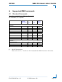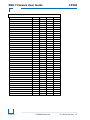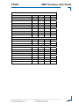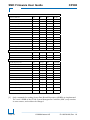
1
System Management Controller
Firmware User Guide
for the
CP308 Board
(based on IPMI)
Manual ID: 1035-8160 Rev. Index 1.0
September 3, 2009
If it's embedded, it's Kontron
SMC Firmware User Guide
1.
CP308
Copyright
Copyright © 2009 Kontron AG
Kontron Modular Computers makes no representations or warranties with respect to the
contents or use of this manual, and specifically disclaims any express or implied warranties of
merchantability or fitness for any particular purpose.
Kontron Modular Computers makes no representations or warranties with respect to this
embedded Linux package, and specifically disclaims any express or implied warranties of
merchantability or fitness for any particular purpose.
Permission is granted to make and distribute verbatim copies of this manual provided that the
copyright notice and this permission notice are preserved on all copies.
Permission is granted to copy and distribute modified versions of this documentation under
the conditions for verbatim copying, provided also that the entire resulting derived work is
distributed under the terms of a permission notice identical to this one.
Permission is granted to copy and distribute translations of this documentation into another
language, under the above conditions for modified versions.
The PICMG® and CompactPCI® names and the PICMG®, CompactPCI®, ATCA®, and
AdvancedTCA® logos are registered trademarks and AdvancedMC is a trademark of the PCI
Industrial Computer Manufacturers Group.
Intel is a registered trademark of Intel Corporation.
I2C is a trademark of Phillips Semiconductors.
Linux is a registered trademark of Linus Torvalds.
All other trademarks, registered trademarks, and trade names are the property of their
respective owners.
Page 2
© 2009 Kontron AG
ID 1035-8160, Rev. 1.0
CP308
2.
SMC Firmware User Guide
Revision History
Manual/Product Title:
User Guide CP308 System Management Controller
Doc. ID:
1035-8160
Revision Index
Brief Description of Changes
Date of Issue
1.0
Initial Issue
03-Sep-2009
Imprint
Kontron Modular Computers GmbH may be contacted via the following:
MAILING ADDRESS
TELEPHONE AND E-MAIL
Kontron Modular Computers GmbH
+49 (0) 800-SALESKONTRON
Sudetenstraße 7
[email protected]
D - 87600 Kaufbeuren Germany
For further information about other Kontron products, please visit our Internet web site:
www.kontron.com
Disclaimer
Copyright © 2009 Kontron AG. All rights reserved. All data is for information purposes only
and not guaranteed for legal purposes. Information has been carefully checked and is believed
to be accurate; however, no responsibility is assumed for inaccuracies. Kontron and the
Kontron logo and all other trademarks or registered trademarks are the property of their
respective owners and are recognized. Specifications are subject to change without notice.
ID 1035-8160, Rev. 1.0
© 2009 Kontron AG
Page 3
SMC Firmware User Guide
3.
CP308
Contents
1.
Copyright ........................................................................................................................... 2
2.
Revision History ................................................................................................................ 3
3.
Contents ............................................................................................................................. 4
4.
Introduction........................................................................................................................ 6
5.
6.
7.
8.
4.1
Acronym Definitions.................................................................................................. 6
4.2
Related Documentation.............................................................................................. 7
4.3
Product Overview ...................................................................................................... 8
4.3.1
CP308 System Management Controller............................................................. 8
4.3.2
System Management based on IPMI ................................................................. 8
System Management Controller ........................................................................................ 9
5.1
Management Controller Hardware............................................................................. 9
5.2
Key Features .............................................................................................................. 9
5.3
Management Controller Firmware........................................................................... 10
5.3.1
Structure and Functionality.............................................................................. 10
5.3.2
Initial uEFI BIOS interaction........................................................................... 10
5.3.3
Board’s Boot Process (uEFI BIOS Flash selection) ........................................ 11
5.3.4
uEFI BIOS Boot Order selection by OEM IPMI command ............................ 12
5.3.5
Setting the SEL time ........................................................................................ 12
5.3.6
OS Shut Down ................................................................................................. 12
5.3.7
Firmware Identification.................................................................................... 13
Supported IPMI Commands ............................................................................................ 15
6.1
Standard Commands ................................................................................................ 15
6.2
PICMG defined OEM Commands........................................................................... 20
6.3
OEM Commands and Extensions ............................................................................ 21
6.3.1
Get Device ID Command with OEM Extensions ............................................ 21
6.3.2
Set/Get Control State OEM commands ........................................................... 21
Board Sensors .................................................................................................................. 24
7.1
Sensor List ............................................................................................................... 24
7.2
Sensor Thresholds .................................................................................................... 27
7.3
OEM sensor types and OEM sensor event/reading types ........................................ 28
System Management LED ............................................................................................... 29
Page 4
© 2009 Kontron AG
ID 1035-8160, Rev. 1.0
CP308
9.
SMC Firmware User Guide
System Management Setup ..............................................................................................30
9.1
EFI BIOS Setup for the System Management..........................................................30
9.1.1
KCS Interface IRQ ...........................................................................................30
9.1.2
Firmware Upgrade............................................................................................30
10. OS Support / Tools ...........................................................................................................31
10.1
Linux tools................................................................................................................31
10.2
OS Support – Board Support Packages ....................................................................31
ID 1035-8160, Rev. 1.0
© 2009 Kontron AG
Page 5
SMC Firmware User Guide
4.
Introduction
4.1
Acronym Definitions
BMC
BSP
FRU
FWH
I2C
IPMB
IPMB-0
IPMI
KCS
MP
PICMG
PWR
SDR
SDRR
SEL
SMBIOS
SMS
SMC
Page 6
CP308
Baseboard Management Controller
In a compact CPCI chassis, there can be only one BMC present. The BMC administrates the
SEL and the SDRR for the complete system. The BMC is connected to the other boards in the
shelf via a dedicated bus (IPMB-0).
Board Support Package
Field Replaceable Unit
Every board is a FRU. The FRU data contains information about the board such as the part
number and the serial number. See PICMG Specification 2.9 for complete details on the FRU
data structure. FRU data is not present on the CP308 Management Controller.
Firmware Hub. Memory location where a complete EFI code is stored.
Inter-Integrated Circuit
Intelligent Platform Management Bus
The dedicated I2C management bus where the BMC and the SMCs communicate.
Intelligent Platform Management Bus which connects all SMCs with the BMC or a Shelf
Manager.
Intelligent Platform Management Interface.
Keyboard Controller Style (Interface)
This is the IPMI mandatory interface on the host system (payload) to communicate with the
Management Controller.
Management Power.
This powers the BMC’s or SMC’s controller and is available as soon as the board is
inserted. A Handle switch needs not be closed for that.
PCI Industrial Computer Manufacturer Group
Payload Power.
This powers the host side of the board where the application software runs.
On the CP308 the payload power is switched on automatically. The Management
Controller of the CP308 observes it.
Sensor Data Record
This is the IPMI data structure that defines a sensor.
Sensor Data Record Repository
Is the device in the BMC where all SDRs of the chassis’ boards are administrated.
The CP308 Management Controller’s repository always contains only the local board’s SDRs.
System Event Log
Is the device in the BMC where all the events in the chassis which are reported are
administrated. If an event occurs on any board, the sensor event is sent throught the IPMB bus
to the BMC. In the Event Log of the CP308 Management Controller only local events are stored.
System Management BIOS
System Management Software (designed to run under the OS)
Satellite Management Controller
In a compact PCI chassis, there can be many SMCs. Each SMC is connected to the BMC via a
dedicated bus (IPMB-0).
The CP308 management controller operates as SMC only.
© 2009 Kontron AG
ID 1035-8160, Rev. 1.0
CP308
4.2
SMC Firmware User Guide
Related Documentation
The CP308 System Management Controller implementation is based on the following IPMI
and PICMG specifications. But the CP308 SMC doesn’t claims to be fully compliant to these
specifications.
IPMI specifications: (http://www.intel.com/design/servers/ipmi/spec.htm)
[1]
IPMI - Intelligent Platform Management Interface Specification v1.5
Document revision 1.1, February 2002
[2]
Addenda, Errata, and Clarifications document revision 4 for IPMI v1.5 rev 1.1
specification
[3]
IPMB - Intelligent Platform Management Bus
Communications Protocol Specification v1.0, Doc. Rev. 1.0, November 1999
[4]
IPMI- IPMB v1.0 Address Allocation
Document Revision 1.0, September 1998
PICMG specifications: http://www.picmg.org
[5]
PICMG 2.9 R1.0 CompactPCI System Management Specification
February 2000
[6]
PICMG 3.0 R2.0 AdvancedTCA Base Specification
March 2005
Open IPMI tools documentation (see also chapter 10, “OS Support / Tools”):
[7]
ipmitool documentation: http://ipmitool.sourceforge.net.
[8]
OpenIPMI documentation: http://www.openipmi.sourceforge.net .
Kontron manuals and specifications: http://www.kontron.com
[9]
CP308 – User Guide – 3U Compact PCI Processor Board
Doc. ID 1027-4487, Rev. 2.0, July 20, 2009
[10]
CP308 uEFI BIOS – User Guide
Doc. ID 1030-4232, Rev. 2.0, July 22, 2009
ID 1035-8160, Rev. 1.0
© 2009 Kontron AG
Page 7
SMC Firmware User Guide
4.3
CP308
Product Overview
4.3.1 CP308 System Management Controller
Although the CP308 SMC implementation is not fully compliant to IPMI v1.5 it should work
with System Management Software (SMS) and IPMI tools, which respect this specification.
Compared with a BMC defined by IPMI, the CP308 SMC is just an IPM Device with some
additional capabilities, to allow SMS or other tools for IPMI to read the sensors and give
access to stored sensor events.
Sensors and Events
The CP308 Sensors are accessible via the KCS System Interface from CP308 Host OS side.
All sensors are monitored and Sensor Events are generated in case of a sensors value is outof-range, refer to 7.1, ‘Sensor List’ and 7.2, ‘Sensor Thresholds’. Generated sensor events are
stored in the local System Event Log (SEL).
Sensor Data Record Repository
Some SMS expects a BMC with an already filled Sensor Data Record Repository (SDRR)
behind a KCS to get current readings of sensors. Normally the SDRR holds information of all
sensors in the system and therefore the SDRR must be filled when the system (or rack) is
setup.
Thus CP308 SMC is intended to provide only information of its own sensors. The CP308
System Management Controller implementation includes a static SDR repository module,
which includes its own sensors. This SDRR has read-only access, i.e. its content is fixed and
could not be changed. This allows SMS to deal with the CP308 SMC to get sensor readings
and access its SEL, like SMS does this with a BMC.
4.3.2 System Management based on IPMI
What is IPMI?
IPMI is an extensible and open standard that defines autonomous system monitoring. It is
autonomous because every management controller within a compact PCI chassis monitors its
own sensors and sends critical events through a dedicated bus to a Baseboard Management
Controller (BMC) that logs it into a non volatile System Event Log (SEL).
You can find more information about the IPMI at the following Web site:
http://www.intel.com/design/servers/ipmi/
CP308 System Management
The CP308 System Management neither implements a fully functional BMC, nor is it
suggested to be fully compliant to the Intelligent Platform Management Interface 1.5
(IPMIv1.5) and PICMG 2.9 R1.0 specifications. This System Management Controller
implementation is just based on it.
Page 8
© 2009 Kontron AG
ID 1035-8160, Rev. 1.0
CP308
SMC Firmware User Guide
5.
System Management Controller
5.1
Management Controller Hardware
On the CP308 processor board, the Management Controller is implemented using the NXP
LPC2136 32-bit microcontroller with 256 kB of internal Flash and 32 kB of RAM. An
external serial EEPROM is used for firmware private data and for storage of sensor events.
The Management Controller implements one local Keyboard Style Interface (KCS) with
interrupt support for communication with system side management software and the uEFI
BIOS. The Management Controllers in the rack are all connected the IPMB bus.
The Management Controller provides access to various board sensors that permit the
monitoring of:
5.2
•
system power voltages: 5V (PWR), 3.3V, 5V (IPMB)
•
processor, memory and board temperature
•
Power Good, IPMB link state, board resets, POST code, boot errors, various
processor states, Health error, etc.
Key Features
•
Based on IPMI specification 1.5, revision 1.1 and PICMG 2.9 CompactPCI
System Management specification
•
KCS SMS interface with interrupt support
•
Single Port IPMB channel from/to CompactPCI backplane.
•
Out of band management and monitoring using IPMB interface permits access to
sensors regardless of the board’s CPU state
•
Sensor thresholds fully configurable
•
Sensor names prefixed with identification of owner (based on slot number)
•
SEL functionality, storing local sensor events
•
Interoperable with other IPMI solutions
•
uEFI BIOS fail-over control, for automatic EFI firmware bank switching after
having detected a not working EFI (refer to chapter 5.3.3.2, “Automatic uEFI
BIOS Flash Selection”).
•
OEM commands for uEFI BIOS firmware bank selection and uEFI BIOS boot
order override (refer to chapters 5.3.3.1 and 5.3.4).
•
OS shutdown support (refer to chapter 5.3.6., “OS Shut Down”).
•
The “Health” LED shows the IPMI controller’s heartbeat and pulses if the KCS
interface is active (refer to chapter 8, “System Management LED”
The complete list of all CP308 SMC sensors (including thresholds and event
generation masks) can be found in chapter 7, “Board Sensors” below.
ID 1035-8160, Rev. 1.0
© 2009 Kontron AG
Page 9
SMC Firmware User Guide
5.3
CP308
Management Controller Firmware
5.3.1 Structure and Functionality
The Management Controller (MC) firmware code is stored in its internal flash area. To allow
observation of the board’s sensors, CPU states and processor board startup, the MC has its
own power supply.
The MC is powered independent of the CPU. On the CP308 a special power controller is used
to turn on power supply of the CPU automatically. The MC has no influence on CPU’s power
supply, it just observes it.
Refer to [9], ‘CP308 – User Guide – 3U Compact PCI Processor Board’ for details.
5.3.1.1 Management Controller Startup
Upon system start the System Management Controller does:
•
A self test to verify the status of the Management Controller’s hardware. The self test
result can be determined using the IPMI command Get Self Test Results.
•
Checks integrity of connected EEPROM, containing internal firmware parameters,
configuration data and the storage of sensor events.
Then it starts monitoring its sensors and provides the sensor and event data to SMS, either via
KCS interface or via IPMB over the backplane.
5.3.1.2 Processor Board Startup
When the processor board gets powered (turned on) or when the system is restarted, the MC
additionally observes correct startup of the system:
•
uEFI BIOS fail-over control
•
POST code observation
Erroneous processor board startup is indicated by the related sensors (events are generated
then) and by the SMC LED.
Refer to the sensors “Health Error”, “POST Value” and “FWHx Boot Err” at chapter 7.1,
‘Sensor List’.
5.3.2 Initial uEFI BIOS interaction
For communication between uEFI BIOS and Management Controller the KCS interface is
used. During the boot process the uEFI BIOS sends the some IPMI and OEM defined
commands to the Management Controller:
•
An OEM command which reports a good or a bad checksum of the current selected
uEFI BIOS firmware bank.
•
The IPMI command ‘Set SEL Time’ to set the event log time to the time which is kept
by processor boards RTC.
Page 10
© 2009 Kontron AG
ID 1035-8160, Rev. 1.0
CP308
SMC Firmware User Guide
•
A Standard IPMI command ‘Set ACPI Power State’ to set an initial state before the
OS boots.
•
An OEM command to get ‘Boot Order Override’ setting from MC.
•
And others.
5.3.3 Board’s Boot Process (uEFI BIOS Flash selection)
When the CP308’s processor starts, the first code executed is the uEFI BIOS. There are two
Flash banks, which may contain different uEFI BIOS firmware. The currently selected one
can be checked from EFI shell using the kboardinfo command. Refer to chapter “uEFI
Shell” of [10], the “CP308 uEFI BIOS – User Guide” for more information.
The selection of uEFI BIOS firmware bank, used for the next boot process can be changed the
following ways:
•
Using a DIP Switch. Refer to [9], the “CP308 – User Guide – 3U Compact PCI
Processor Board” for details.
•
From Management Controller side
o Using OEM IPMI command
o Automatically by the uEFI BIOS fail-over control
5.3.3.1 uEFI BIOS Flash Selection by OEM IPMI command
Using the OEM IPMI command ‘Get Control State’ the current selected uEFI BIOS bank, set
by the MC, can be determined. With the OEM IPMI command ‘Set Control State’ this setting
can be changed. This setting is always kept as a non volatile parameter, i.e. is restored after
power-off / power-on cycles. Please refer to 6.3.2, “Set/Get Control State OEM commands”
using ‘Control ID’ for ‘EFI Flash selection’.
5.3.3.2 Automatic uEFI BIOS Flash Selection
After each board processor reset the Management Controller selects the uEFI BIOS flash by
applying the related non volatile parameter. Then it waits for a message from the uEFI BIOS.
This message contains a checksum report, i.e. it reports whether the boot Flash’s checksum is
right or wrong.
If either the checksum is wrong or the message is not received within a given time, then the
currently used uEFI BIOS is assumed to contain an invalid or a corrupted image. In this case
the Management Controller toggles the related non volatile parameter and generates a “Boot
Error - Invalid boot sector - event”. The sensor event is generated either by sensor “FWH0
Boot Err” or “FWH1 Boot Err”, dependent on which uEFI BIOS bank failed.
After selecting the alternate uEFI BIOS bank, the board processor is reset and the
Management Controller waits for the checksum report message from EFI again.
The number of retries (wait f. checksum / switch bank / reset) depends on the error condition:
•
2 retries on timeouts (no message from EFI at all)
•
4 retries when a checksum error is reported from EFI
ID 1035-8160, Rev. 1.0
© 2009 Kontron AG
Page 11
SMC Firmware User Guide
CP308
Note: The number within the names of the two related sensors “FWH0/1 Boot Err”
corresponds to the value of the non volatile parameter, not to the absolute number of the uEFI
BIOS firmware bank (which is not known by the MC).
5.3.4 uEFI BIOS Boot Order selection by OEM IPMI command
Normally the EFI will apply the boot order which was selected in the uEFI BIOS menu
“Boot/Boot Option Priorities”. But there is another alternative boot order which is held in the
Management Controller’s non volatile memory. This boot order can be changed or just read
by IPMI OEM commands.
During boards boot process the uEFI BIOS read this value from the Management Controller’s
stored boot order. The uEFI BIOS will use this setting, instead of its own boot order setting.
Please refer to chapter 6.3.2, “Set/Get Control State OEM commands” using the ‘Control ID’
for ‘EFI Boot Order Configuration’, for details.
5.3.5 Setting the SEL time
The Management Controller has no own hardware real time clock, but requires current time to
generate sensor events with a correct timestamp. So every time when the EFI comes up, the
EFI supply the time from board processor’s RTC to the Management Controller. Without this
the sensor events will have an out-of-date time stamp.
Note:
When the Management Controller restarts without getting the time from EFI (for example
executing the IPMI command ‘Cold Reset’), no actual time is available. Application software
may send an IPMI command ‘Set SEL Time’ via the KCS interface or by a remote
Management Controller via the IPMB to set the correct time again.
5.3.6 OS Shut Down
The Management Controller allows a shut down of the Operating System (OS) using a
PICMG defined OEM IPMI command. This requires an OS which supports APCI power
states. Using the PICMG command ‘FRU Control’ with ‘Option’ set to 04h = Quiesce will
result in an shutdown of the Operating System.
The IPMI specification defines two commands which allow the Management Controller to
track the current APCI power state. Theses are the commands ‘Set ACPI Power State’ and
‘Get ACPI Power State‘. The IPMI command ‘Set ACPI Power State’ doesn’t have impact on
the real power state. It just informs the Management Controller about it.
The uEFI BIOS ACPI sets the initial power state to ‘ACPI legacy on’ on system startup
(before the OS boots) using the IPMI command.
An ACPI capable OS sets the state to ‘S0/G0 working’ when it has reprogrammed the chip set
in a manner that a “power button” signal doesn’t lead to an immediate power off, but causes
an event that can be detected by the OS which then leads to an OS shutdown.
When the OS is (almost) shut down it sets the ACPI state to ‘S5/G2 soft off’.
Page 12
© 2009 Kontron AG
ID 1035-8160, Rev. 1.0
CP308
SMC Firmware User Guide
The current set ACPI state can be determined either by the IPMI command ‘Get ACPI Power
State‘ or by reading the dedicated sensor “ACPI State”. Both ways are possible via KCS (only
when the OS is up) or via IPMB by a Management Controller of another board in the rack.
Notes:
Compared to ATCA blades, where a ‘graceful shutdown’ is initiated by pulling the handleswitch and indicated by a blue LED and the MC is capable of switching payload power on or
off, the CP308 doesn’t have such ATCA features. Refer to [9], “CP308 – User Guide – 3U
Compact PCI Processor Board” for details.
On the CP308 a special power controller is used to turn on power supply of the CPU
automatically. The MC has no influence on CPU’s power supply, it just observes it.
The operator is in responsibility, that all boards in the system are shut down, before the power
is switched off.
5.3.7 Firmware Identification
There are two ways, by means of IPMI, to identify the CP308 System Management Controller
Firmware.
•
Issuing a IPMI Command Get Device ID
•
Read the Device Locator Record (SDR Type 12h)
A full description of the IPMI command ‘Get Device ID’ and for the Device Locator Record
(SDR Type 12h) format can be found at [1], “IPMI - Intelligent Platform Management
Interface Specification v1.5”.
IPMI Command ‘Get Device ID’
The response on the IPMI command ‘Get Device ID’ offers the following information (among
others):
•
Manufacturer ID = 3A98h (Kontron IANA ID)
•
Device ID = 20h (NXP LPC2136)
•
Product ID = 0134h = 308 identifies the board as a CP308
•
Firmware Revision in bytes 4:5 - depends on the core version of the running firmware.
•
The SDR revision in byte 13 (OEM part of the response) is a sub revision of the
firmware revision. It is unique for all versions of the board’s firmware i.e. the
Firmware Revision mentioned above is not really needed for the identification of the
firmware.
For a description of the OEM extensions refer to chapter 6.3.1, “Get Device ID Command
with OEM Extensions”
ID 1035-8160, Rev. 1.0
© 2009 Kontron AG
Page 13
SMC Firmware User Guide
CP308
Device Locator Record
The Device Locator Record (SDR Type 12h) contains a Device ID String. This string
identifies the MC as CP308 SMC, and also holds some run-time information like slot number
and the slot dependent IPMB address.
For example when using the Linux ipmitool [7], on a CP308 placed in 8th slot of CompactPCI
system, by calling:
ipmitool sdr list mcloc
The following information is displayed:
S08:CP308
| … @BEh
| ok
Where S08 identifies the slot number, and @BEh the IPMB address derived from the slot
number.
Page 14
© 2009 Kontron AG
ID 1035-8160, Rev. 1.0
CP308
SMC Firmware User Guide
6.
Supported IPMI Commands
6.1
Standard Commands
Part of the command list in IPMI specification 2.0
M = mandatory, O = optional
IPMI 2.0
Spec. section
NetFn
CMD
Kontron
support
On SMC
IPM Device “Global”
Commands
Get Device ID
M
20.1
App
01h
M / Yes [1]
Cold Reset
20.2
App
02h
O / Yes
Warm Reset
20.3
App
03h
O / No
Get Self Test Results
20.4
App
04h
O / Yes
Manufacturing Test On
20.5
App
05h
O / No
Set ACPI Power State
20.6
App
06h
O / Yes
Get ACPI Power State
20.7
App
07h
O / Yes
Get Device GUID
20.8
App
08h
O / No
Broadcast “Get Device ID”
20.9
App
01h
M / Yes
BMC Watchdog Timer
Commands
O
Reset Watchdog Timer
27.5
App
22h
O / No
Set Watchdog Timer
27.6
App
24h
O / No
Get Watchdog Timer
27.7
App
25h
O / No
[1]
Has OEM extensions.
Please refer to 6.3.1, “Get Device ID Command with OEM Extensions” for details.
ID 1035-8160, Rev. 1.0
© 2009 Kontron AG
Page 15
SMC Firmware User Guide
CP308
BMC Device and Messaging Commands
O
Set BMC Global Enables
22.1
App
2Eh
Get BMC Global Enables
22.2
App
2Fh
O / Yes
O / Yes
Clear Message Flags
22.3
App
30h
O / Yes
Get Message Flags
22.4
App
31h
O / Yes
Enable Message Channel Receive
22.5
App
32h
O / Yes
Get Message
22.6
App
33h
O / Yes
Send Message
22.7
App
34h
O / Yes
Read Event Message Buffer
22.8
App
35h
O / Yes
Get BT Interface Capabilities
22.9
App
36h
O / No
Get System GUID
22.14
App
37h
O / No
Get Channel Authentication Capabilities
22.13
App
38h
O / No
Get Session Challenge
22.15
App
39h
O / No
Activate Session
22.17
App
3Ah
O / No
Set Session Privilege Level
22.18
App
3Bh
O / No
Close Session
22.19
App
3Ch
O / No
Get Session Info
22.20
App
3Dh
O / No
Get AuthCode
22.21
App
3Fh
O / No
Set Channel Access
22.22
App
40h
O / No
Get Channel Access
22.23
App
41h
O / No
Get Channel Info
22.24
App
42h
O / Yes
Set User Access
22.26
App
43h
O / No
Get User Access
22.27
App
44h
O / No
Set User Name
22.28
App
45h
O / No
Get User Name
22.29
App
46h
O / No
Set User Password
22.30
App
47h
O / No
Activate Payload
24.1
App
48h
O / No
Deactivate Payload
24.2
App
49h
O / No
Get Payload Activation Status
24.4
App
4Ah
O / No
Get Payload Instance Info
24.5
App
4Bh
O / No
Set User Payload Access
24.6
App
4Ch
O / No
Get User Payload Access
24.7
App
4Dh
O / No
Get Channel Payload Support
24.8
App
4Eh
O / No
Get Channel Payload Version
24.9
App
4Fh
O / No
Get Channel OEM Payload Info
24.10
App
50h
O / No
Master Write-Read
22.11
App
52h
O / No
Get Channel Cipher Suits
22.15
App
54h
O / No
Suspend/Resume Payload Encryption
24.3
App
55h
O / No
Set Channel Security Keys
22.25
App
56h
O / No
Get System Interface Capabilities
22.9
App
57h
O / No
Page 16
© 2009 Kontron AG
ID 1035-8160, Rev. 1.0
CP308
SMC Firmware User Guide
Chassis Device Commands
O
Get Chassis Capabilities
28.1
Chassis
00h
O / No
Get Chassis Status
28.2
Chassis
01h
O / No
Chassis Control
28.3
Chassis
02h
O / No
Chassis Reset
28.4
Chassis
03h
O / No
Chassis Identify
28.5
Chassis
04h
O / No
Set Chassis Capabilities
28.7
Chassis
05h
O / No
Set Power Restore Policy
28.8
Chassis
06h
O / No
Get System Restart Cause
28.11
Chassis
07h
O / No
Set System Boot Options
28.12
Chassis
08h
O / No
Get System Boot Options
28.13
Chassis
09h
O / No
Get POH Counter
28.14
Chassis
0Fh
O / No
Event Commands
Set Event Receiver
M
29.1
S/E
01h
M / Yes
Get Event Receiver
29.2
S/E
02h
M / Yes
Platform Event (a.k.a. “Event Message”)
29.3
S/E
03h
M / Yes
PEF and Alerting Commands
O
Get PEF Capabilities
30.1
S/E
10h
O / No
Arm PEF Postpone Timer
30.2
S/E
11h
O / No
Set PEF Configuration Parameters
30.3
S/E
12h
O / No
Get PEF Configuration Parameters
30.4
S/E
13h
O / No
Set Last Processed Event ID
30.5
S/E
14h
O / No
Get Last Processed Event ID
30.6
S/E
15h
O / No
Alert Immediate
30.7
S/E
16h
O / No
PET Acknowledge
30.8
S/E
17h
O / No
ID 1035-8160, Rev. 1.0
© 2009 Kontron AG
Page 17
SMC Firmware User Guide
CP308
Sensor Device Commands
M
Get Device SDR Info
35.2
S/E
20h
M / Yes
Get Device SDR
35.3
S/E
21h
M / Yes
Reserve Device SDR Repository
35.4
S/E
22h
M / Yes
Get Sensor Reading Factors
35.5
S/E
23h
O / No
Set Sensor Hysteresis
35.6
S/E
24h
O / Yes
Get Sensor Hysteresis
35.7
S/E
25h
O / Yes
Set Sensor Threshold
35.8
S/E
26h
O / Yes
Get Sensor Threshold
35.9
S/E
27h
O / Yes
Set Sensor Event Enable
35.10
S/E
28h
O / Yes
Get Sensor Event Enable
35.11
S/E
29h
O / Yes
Re-arm Sensor Events
35.12
S/E
2Ah
O / No
Get Sensor Event Status
35.13
S/E
2Bh
O / No
Get Sensor Reading
35.14
S/E
2Dh
M / Yes
Set Sensor Type
35.15
S/E
2Eh
O / No
Get Sensor Type
35.16
S/E
2Fh
O / No
Get FRU Inventory Area Info
34.1
Storage
10h
No
Read FRU Data
34.2
Storage
11h
No
Write FRU Data
34.3
Storage
12h
No
FRU Device Commands
SDR Device Commands
O
Get SDR Repository Info
33.9
Storage
20h
O / Yes [2]
Get SDR Repository Allocation Info
33.10
Storage
21h
O / Yes [2]
Reserve SDR Repository
33.11
Storage
22h
O / Yes [2]
Get SDR
33.12
Storage
23h
O / Yes [2]
Add SDR
33.13
Storage
24h
O / No
Partial Add SDR
33.14
Storage
25h
O / No
Delete SDR
33.15
Storage
26h
O / No
Clear SDR Repository
33.16
Storage
27h
O / No
Get SDR Repository Time
33.17
Storage
28h
O / No
Set SDR Repository Time
33.18
Storage
29h
O / No
Enter SDR Repository Update Mode
33.19
Storage
2Ah
O / No
Exit SDR Repository Update Mode
33.20
Storage
2Bh
O / No
Run Initialization Agent
33.21
Storage
2Ch
O / No
[2]
Only commands for reading Sensor Data Record Repository (SDRR) are implemented.
The ‘static’ SDRR of the CP308 System Management Controller (SMC) only contains
its own sensors, and could not be changed.
Page 18
© 2009 Kontron AG
ID 1035-8160, Rev. 1.0
CP308
SMC Firmware User Guide
SEL Device Commands
O
Get SEL Info
40.2
Storage
40h
O / Yes
Get SEL Allocation Info
40.3
Storage
41h
O / Yes
Reserve SEL
40.4
Storage
42h
O / Yes
Get SEL Entry
40.5
Storage
43h
O / Yes
Add SEL Entry
40.6
Storage
44h
O / Yes
Partial Add SEL Entry
40.7
Storage
45h
O / No
Delete SEL Entry
40.8
Storage
46h
O / Yes
Clear SEL
40.9
Storage
47h
O / Yes
Get SEL Time
40.10
Storage
48h
O / Yes
Set SEL Time
40.11
Storage
49h
O / Yes
Get Auxiliary Log Status
40.12
Storage
5Ah
O / No
Set Auxiliary Log Status
40.13
Storage
5Bh
O / No
LAN Device Commands
O
Set LAN Configuration Parameters
23.1
Transport
01h
O / No
Get LAN Configuration Parameters
23.2
Transport
02h
O / No
Suspend BMC ARPs
23.3
Transport
03h
O / No
Get IP/UDP/RMCP Statistics
23.4
Transport
04h
O / No
Serial/Modem Device Commands
O
Set Serial/Modem Configuration
25.1
Transport
10h
O / No
Get Serial/Modem Configuration
25.2
Transport
11h
O / No
Set Serial/Modem Mux
25.3
Transport
12h
O / No
Get TAP Response Codes
25.4
Transport
13h
O / No
Set PPP UDP Proxy Transmit Data
25.5
Transport
14h
O / No
Get PPP UDP Proxy Transmit Data
25.6
Transport
15h
O / No
Send PPP UDP Proxy Packet
25.7
Transport
16h
O / No
Get PPP UDP Proxy Receive Data
25.8
Transport
17h
O / No
Serial/Modem Connection Active
25.9
Transport
18h
O / No
Callback
25.10
Transport
19h
O / No
Set User Callback Options
25.11
Transport
1Ah
O / No
Get User Callback Options
25.12
Transport
1Bh
O / No
SOL Activating
26.1
Transport
20h
O / No
Get SOL Configuration Parameters
26.2
Transport
21h
O / No
Set SOL Configuration Parameters
26.3
Transport
22h
O / No
ID 1035-8160, Rev. 1.0
© 2009 Kontron AG
Page 19
SMC Firmware User Guide
6.2
CP308
PICMG defined OEM Commands
Spec. Table
NetFn
CMD
Partially
supported
3-11
PICMG
00h
Yes
Get Address Info
PICMG
01h
N/A
Get Shelf Address Info
PICMG
02h
N/A
Set Shelf Address Info
PICMG
03h
N/A
PICMG
04h
Yes [3]
Get FRU LED Properties
PICMG
05h
N/A
Get LED Color Capabilities
PICMG
06h
N/A
Set FRU LED State
PICMG
07h
N/A
Get FRU LED State
PICMG
08h
N/A
Set IPMB State
PICMG
09h
N/A
Set FRU Activation Policy
PICMG
0Ah
N/A
Get FRU Activation Policy
PICMG
0Bh
N/A
Set FRU Activation
PICMG
0Ch
N/A
PICMG
0Dh
Yes
Set Port State
PICMG
0Eh
N/A
Get Port State
PICMG
0Fh
N/A
Compute Power Properties
PICMG
10h
N/A
Set Power Level
PICMG
11h
N/A
Get Power Level
PICMG
12h
N/A
Renegotiate Power
PICMG
13h
N/A
Get Fan Speed Properties
PICMG
14h
N/A
Set Fan Level
PICMG
15h
N/A
Get Fan Level
PICMG
16h
N/A
Bused Resource
PICMG
17h
N/A
Get IPMB Link Info
PICMG
18h
N/A
1Eh
Yes
PICMG® 3.0 Rev 3.0 with Errata
Get PICMG Properties
FRU Control
Get Device Locator Record ID
3-27
3-39
PICMG
FRU Control Capabilities
[3]
3-26
PICMG
FRU Control Option (request byte 3):
Only 00h = ‘Cold Reset’ and 04h = ‘Quiesce’ are implemented.
Both options are reserved (i.e. not optional) in the FRU Control Capabilities mask.
Page 20
© 2009 Kontron AG
ID 1035-8160, Rev. 1.0
CP308
6.3
SMC Firmware User Guide
OEM Commands and Extensions
6.3.1 Get Device ID Command with OEM Extensions
The IPMI specification defines four optional bytes in the response to ‘Get Device ID’. The
response bytes [13:14] hold the ‘Auxiliary Firmware Revision Information’.
LUN
Get Device ID command with OEM extensions
Byte
00h
NetFn
CMD
App = 06h
01h
Data Field
Request Data
-
-
Response Data
1
Completion Code
2:12 Regular Get Device ID Command response fields
13
Release number of the management controller firmware.
10h for R10,
11h for R11,
…
14
Boards Geographical Address (slot number) read from
backplane:
0 = reserved
1… = slot 1 … max. slot number
15
00h: Reserved
16
00h: Reserved
6.3.2 Set/Get Control State OEM commands
With the two OEM IPMI commands ‘Set Control State’ and ‘Get Control State’ firmware
non-volatile parameters can be read or changed. The parameter is selected by using the
dedicated ‘Control ID’, the parameter’s value (i.e. it value range) depends on this selection.
ID 1035-8160, Rev. 1.0
© 2009 Kontron AG
Page 21
SMC Firmware User Guide
CP308
6.3.2.1 Get Control State
LUN
Set Control State (Firmware Hub / EFI Flash, Boot
Order, IPMB Sensor Monitoring Mode)
Byte
Request data
00h
NetFn
CMD
OEM = 3Eh
20h
Data Field
1
Control ID
00h: EFI Flash selection
10h: IPMB Sensor Monitoring Mode
9Dh: EFI Boot Order Configuration
2
Control State for EFI Flash selection *):
00h = EFI Flash selection is not inverted
01h = EFI Flash selection is logically inverted
Control State for IPMB Sensor Monitoring Mode**):
10h = (Default) IPMB related Sensor events disabled.
11h = IPMB related Sensors generate events
Control State for EFI Boot Order Configuration:
00h .. 07h = Selected EFI Boot Order Configuration.
00h selects the Boot Order which is set in the EFI.
BIOS boot order configuration:
000b = Boot order is according to EFI setup (default)
001b = Next boot device class: FDD
010b = Next boot device class: HDD
011b = Next boot device class: CD-ROM
100b = Next boot device class: Network
101b = Next boot device class: USB FDD
110b = Next boot device class: USB HDD
111b = Next boot device class: USB CD-ROM
Response data
*)
Page 22
1
Completion code
Please note that this selection will be automatically toggled by the Management
Controller during a failing boot process. Other payload sided settings may also
modify the uEFI BIOS bank selection (a DIP switch for example).
© 2009 Kontron AG
ID 1035-8160, Rev. 1.0
CP308
**)
SMC Firmware User Guide
The IPMB/IPMI voltage, observed by sensors ‘Board 5VIPMI’ and ‘IPMB State’ is
normally provided by the backplane. But this is not the default option for 3U
Compact PCI racks.
6.3.2.2 Get Control State
LUN
Get Control State (Firmware Hub/EFI Flash, Boot
Order, IPMB Sensor Monitoring Mode)
Byte
00h
NetFn
OEM = 3Eh
CMD
21h
Data Field
Request data
1
Control ID
00h: EFI Flash selection
10h: IPMB Sensor Monitoring Mode
9Dh: EFI Boot Order Configuration
Response data
1
Completion code
4
Current Control State (refer to 6.3.2.1, “Get Control State”
ID 1035-8160, Rev. 1.0
© 2009 Kontron AG
Page 23
SMC Firmware User Guide
7.
CP308
Board Sensors
The Management Controller includes many sensors for voltage or temperature monitoring and
various others for pass/fail type signal monitoring.
Every sensor is associated with a Sensor Data Record (SDR). Sensor Data Records contain
information about the sensors identification such as sensor type, sensor name, sensor unit.
SDRs also contain the configuration of a specific sensor such as thresholds, hysteresis, event
generation capabilities, etc. that specify the sensor’s behavior. Some fields of the sensor SDR
are configurable using IPMI commands and are set to a built-in initial value.
Board sensors that have been implemented are listed in the sensor list below.
7.1
Sensor List
The sensor name (ID string) has a prefix which is ‘SXX:’ in the table below. ‘XX’ is replaced
with the slot number during runtime (e.g. ‘S08’ is the prefix for the sensors of a CP308 in the
8th slot). When reading the sensor name the prefix is automatically adapted to the physical
position (slot number) of the board in a rack.
Sensor Type and Event/Reading Type Codes are described by the IPMI specification [1] in
detail. Kontron OEM specific sensor type codes and event/reading type codes are described in
chapter 7.3.
SENSOR Number /
ID string
SENSOR TYPE
(CODE) /
EVENT/READING
TYPE (CODE)
Ass.
Mask /
Deass.
Mask /
Reading
Mask
DESCRIPTION
Causes red
Health LED
on error *) /
Reading
Mask
00h /
SXX:Temp CPU
Temperature (01h) /
Threshold (01h)
7A95h /
7A95h /
3F3F
CPU die temperature
Y
/ 0F3Ch
01h /
SXX:Temp Board
Temperature (01h) /
Threshold (01h)
7A95h /
7A95h /
3F3F
Temperature sensor
close to processor
Y
/ 0F3Ch
02h /
SXX:Temp SODIMM
Temperature (01h) /
Threshold (01h)
7A95h /
7A95h /
3F3F
Temperature sensor
close to SODIMM socket
Y
/ 0F3Ch
03h /
SXX:Pwr Good
Power supply (08h) /
OEM (73h)
0000h /
0000h /
400Dh
Status of power lines
N
04h /
SXX:Pwr Good Evt
Power supply (08h) /
OEM (73h)
0000h /
400Dh /
400Dh
Power fail events for
power lines
Y
/ 400Dh
05h /
SXX:Board 3.3V
Voltage (02h) /
Threshold ( 01h)
2204h /
2204h /
1212h
Board 3.3V supply
Y
/ 0F3Ch
Page 24
© 2009 Kontron AG
(PGOOD_MAIN,
HS_FAULT_3V3#,
CPCI1_DEG_3V3#,
CPCI1_FAL_3V33#)
ID 1035-8160, Rev. 1.0
CP308
SENSOR Number /
ID string
SMC Firmware User Guide
SENSOR TYPE
(CODE) /
EVENT/READING
TYPE (CODE)
Ass.
Mask /
Deass.
Mask /
Reading
Mask
∗∗
DESCRIPTION
Causes red
Health LED
on error *) /
Reading
Mask
06h /
SXX:Board 5VIPMI
Voltage (02h) /
Threshold ( 01h)
2204h ) /
∗∗
2204h ) /
1212h
IPMI/IPMB Power 5V,
from/to backplane
N
/ 0F3Ch
07h /
SXX:Board 5.0V
Voltage (02h) /
Threshold ( 01h)
2204h /
2204h /
1212h
Board 5V supply
Y
/ 0F3Ch
08h /
SXX:Fan1 Speed
Fan (04h) /
Threshold (01h)
0000h /
0000h /
1B1Bh
Speed [rpm] Fan 1
N
09h /
SXX:Last Reset
OEM (CFh) /
‘digital’ Discrete (03h)
0002h /
0000h /
0003h
Board reset event
N
0Ah /
SXX:Slot System
Entity presence (25h) /
Sensor-specific (6Fh)
0000h /
0000h /
0003h
Board is in System Slot
(SYSEN)
N
0Bh /
SXX:IPMB State
IPMB status change
(F1h) /
Sensor-specific (6Fh)
000Fh
0000h /
000Fh
IPMB-0 state (refer to
PICMG 3.0 Rev 2.0,
3.8.4.1)
N
0Ch /
SXX:ACPI State
System ACPI Power
State (022h) /
Sensor-specific (6Fh)
7FFFh /
0000h /
7FFFh
System ACPI Power
State
N
0Dh /
SXX:Health Error
Platform Alert (24h) /
‘digital’ Discrete (03h)
0000h /
0000h /
0003h
Aggregates sensors
(power, voltages etc.).
Visualized by SMC LED.
N
0Eh /
SXX:CPU 0 Status
Processor (07h) /
Sensor-specific (6Fh)
0463h /
0400h /
04E3h
CPU status.
Offset 0ah: “Processor
Automatically Throttled”
Y
/ 0402h
0Fh /
SXX:POST Value
POST value OEM
(C6h) /
Sensor-specific (6Fh)
4000h /
0000h /
40FFh
POST code value (port
80h)
N
10h /
SXX:FWH0 BootErr
Boot error (1Eh) /
Sensor-specific (6Fh)
0008h /
0008h /
0008h
Firmware Hub 0 (Boot
Flash 0) boot error
Y
/ 0008h
11h /
SXX:FWH1 BootErr
Boot error (1Eh) /
Sensor-specific (6Fh)
0008h /
0008h /
0008h
Firmware Hub 1 (Boot
Flash 1) boot error
Y
/ 0008h
12h /
SXX:IPMC Storage
Mngmt. Subsystem
Health (28h) /
Sensor-specific (6Fh)
0002h /
0000h /
0003h
IPMI controller storage
access error
Y
/ 0002h
13h /
SXX:IpmC Reboot
Platform Alert (24h) /
‘digital’ Discrete (03h)
0002h /
0000h /
0003h
2 = Management
controller is (re-)booting
N
ID 1035-8160, Rev. 1.0
∗∗∗ )
/
© 2009 Kontron AG
Page 25
SMC Firmware User Guide
SENSOR Number /
ID string
SENSOR TYPE
(CODE) /
EVENT/READING
TYPE (CODE)
Ass.
Mask /
Deass.
Mask /
Reading
Mask
CP308
DESCRIPTION
Causes red
Health LED
on error *) /
Reading
Mask
14h /
SXX:SEL State
Event Logging
Disabled (10h) /
Sensor-specific (6Fh)
003Ch /
0000h /
003Ch
State of event logging
N
15h /
SXX:IPMI Info-1
OEM Firmware Info 1
(C0h) /
OEM (70h)
0003h /
0000h /
7FFFh
For internal use only
N
16h /
SXX:IPMI Info-2
OEM Firmware Info 2
(C0h) /
OEM (71h)
0003h /
0000h /
7FFFh
For internal use only
N
17h /
SXX:Board Rev
OEM Board Revision
(CEh)/
Sensor-specific (6Fh)
0000h /
0000h /
7FFFh
Board revision
information
N
*)
Please note that the “Health” LED is always red if the payload is not active,
i.e. the OS is shut down.
**)
Event Generation of sensor ‘Board 5VIPMI’ is disabled by default.
***)
Event Generation of sensor ‘IPMB State’ is disabled by default.
IPMB voltage is optional (not default) on 3U cPCI backplanes.
Page 26
© 2009 Kontron AG
ID 1035-8160, Rev. 1.0
1)
n.a. 1)
4.703 V
n.a. 1)
4.750 V
4.984 V
5.242 V
n.a. 1)
5.288 V
n.a. 1)
4.680 V
n.a. 1)
4.750 V
4.984 V
5.242 V
n.a. 1)
5.312 V
n.a. 1)
6h /
SXX:Board
5VIPMI
ID 1035-8160, Rev. 1.0
© 2009 Kontron AG
n.a. 1)
3.502 V
n.a. 1)
3.472 V
3.304 V
3.144 V
n.a. 1)
3.114 V
n.a. 1)
5h /
SXX:Board 3.3V
65 °C
75 °C
80 °C
65 °C
75 °C
80 °C
95 °C
95 °C
90 °C
0 °C
0 °C
90 °C
-1 °C
-3 °C
-5 °C
1h /
SXX:Temp Board
-1 °C
-3 °C
-5 °C
2h /
SXX:Temp
SODIMM
115 °C
105 °C
95 °C
90 °C
80 °C
0 °C
-1 °C
-3 °C
-5 °C
0h /
SXX:Temp CPU
Upper non
recoverable
Upper critical
Upper non
critical
Normal max
Nominal
Normal min
Lower non
critical
Lower critical
Lower non
recoverable
SENSOR
Number /
ID string
7.2
n.a. 1)
7h /
SXX:Board 5.0V
CP308
SMC Firmware User Guide
Sensor Thresholds
Not applicable i.e. not used and not settable
Page 27
SMC Firmware User Guide
7.3
CP308
OEM sensor types and OEM sensor event/reading types
Specification of PICMG specific OEM sensors can be found in AdvancedTCA Base
specification.
OEM
SENSOR
TYPE (CODE)
OEM
EVENT/READING
TYPE (CODE)
DESCRIPTION
Firmware Info 1 (C0h)
70h
Internal Diagnostic Data
Firmware Info 2 (C0h)
71h
Internal Diagnostic Data
POST Value (C6h)
6Fh
(sensor type specific)
Error is detected if the POST code is not equal to 00h
and doesn’t change for a defined amount of time.
In case of no error:
Bits [7:0] = POST code (payload Port 80h)
In case of error:
Bits [15:0] = 4000h
Data2 = POST code, low nibble
Data3 = POST code, high nibble
Board Reset (CFh)
03h
(‘digital’ Discrete)
Data 2 contains the reset type:
…WARM = 0
…COLD = 1
…FORCED_COLD = 2
…SOFT_RESET = 3
…MAX = 4
Data 3 contains the reset source:
…IPMI_WATCHDOG = 0
…IPMI_COMMAND = 1
…PROC_INT_CHECKSTOP = 2
…PROC_INT_RST = 3
…RESET_BUTTON = 4
…POWER_UP = 5
…LEG_INITIAL_WATCHDOG = 6
…LEG_PROG_WATCHDOG = 7
…SOFTWARE_INITIATED = 8
…SETUP_RESET = 9
…UNKNOWN = 0xFF
Page 28
© 2009 Kontron AG
ID 1035-8160, Rev. 1.0
CP308
OEM
SENSOR
TYPE (CODE)
e.g. for
Power Good /
Power Good Event
Board revision (CEh)
SMC Firmware User Guide
OEM
EVENT/READING
TYPE (CODE)
73h
6Fh
(sensor type specific)
DESCRIPTION
Sensorspecific Offset
Event
Bit set = o.k.
0h
HS fault#
1h
n.a.
2h
DEG#
3h
FAL#
4h
n.a.
5h
n.a.
6h
n.a.
7h
n.a.
8h
n.a.
9h
n.a.
Ah
n.a.
Bh
n.a.
Ch
n.a.
Dh
n.a.
Eh
Power Good Main
Bits [7:0] = Board Revision number
This corresponds to Board and PLD Revision register
described in CP6016 board manual.
8. System Management LED
There are is one LED on the face plate, controlled by the System Management Controller.
SMC LED (Health)
Color:
Green / red
Labeled: ‘SMC LED’
Behavior: Blinking = Management controller is running, showing its heart beat.
Pulsing = KCS interface active.
Off = Management controller is not running.
Any action, green = No health error detected (refer to sensor “Health Error”).
Any action, red = Health error detected.
ID 1035-8160, Rev. 1.0
© 2009 Kontron AG
Page 29
SMC Firmware User Guide
CP308
9. System Management Setup
9.1
EFI BIOS Setup for the System Management
For initial setup and to get some basic information of the CP308 System Management
Controller the CP308 EFI shell is used. Refer to chapter ‘uEFI Shell’ of [10], ‘CP308 uEFI
BIOS – User Guide’ for more information.
Beside the built-in uEFI Shell commands the Kontron uEFI implementation provides a
number of additional commands, related to the specific HW features of the system.
The Kontron uEFI Shell command for configuration of the System Management is the kipmi
command. The kipmi command provides a set of parameters to support various (IPMI)
Management controllers. Not all parameters have impact on the CP308 System Management.
On the CP308 the kipmi command may be used with following parameters:
•
kipmi
without any parameter, displays a list of available parameters.
•
kipmi irq
provides information about currently selected IRQ used for KCS
System Interface. An additional parameter 10, 11 or 0, sets KCS IRQ
configuration to IRQ10, IRQ11 or to no IRQ at all.
•
kipmi sel
may be used (with additional parameters) to deal with the System
Event Log (SEL), for example clear the SEL or displaying a single
entry.
•
kipmi raw
for execution of raw IPMI commands (also with additional
parameters).
Using the kipmi command with other parameters than those listed here, don’t have any
impact on the CP308 System Management Controller.
9.1.1 KCS Interface IRQ
The default factory setting of a CP308 for its KCS interface is ‘no IRQ’. When changing the
configuration, the EFI creates/updates an entry in the SMBIOS table. This record contains
information about (among others):
•
type of the supported interface (KCS style)
•
chosen interrupt (10, 11 or none)
This information is needed by the Operating System’s KCS interface kernel driver when it is
loaded. Changing the KCS interrupt number from EFI shell needs a restart of the EFI BIOS
for a correct set up of the SMBIOS table. So issue a reset command (instead of the exit
command) to leave the EFI shell when having changed the KCS Interrupt selection.
9.1.2 Firmware Upgrade
This board’s Management Controller Firmware can be updated using the ‘Firmware Update
CD for CP308’. Boot the CP308 from the Update CD and follow the onscreen instructions to
update either Management Controller firmware or uEFI BIOS or both.
Page 30
© 2009 Kontron AG
ID 1035-8160, Rev. 1.0
CP308
SMC Firmware User Guide
10. OS Support / Tools
10.1 Linux tools
OpenIPMI - KCS driver
Normally all drivers and kernel modules needed for communication between the payload
sided software and the Management Controller firmware via the KCS interface come with the
distribution. Newest sources can be downloaded from http://openipmi.sourceforge.net. There
may be downloaded the OpenIPMI project as well. The OpenIPMI library package includes
some applications and the needed libraries.
IPMI Tool
Another very useful all-in-one tool is ‘ipmitool’ [1] ( http://ipmitool.sourceforge.net ). It
provides a user friendly interface to many IPMI features and extensions, for example to get
sensor reading, change sensor thresholds, to access the SEL or to access other Management
Controllers via IPMB. Before ‘ipmitool’ can be used the OpenIPMI driver, mentioned above,
must be loaded too.
10.2 OS Support – Board Support Packages
To see which Operating Systems are supported refer to the board’s data sheet, please visit
http://www.kontron.com to get the data sheet. Also have a look in the download section for
latest versions of Board Support Packages or Firmware Updates.
For information about IPMI refer to the BSP’s documentation of the dedicated OS.
ID 1035-8160, Rev. 1.0
© 2009 Kontron AG
Page 31
SMC Firmware User Guide
CP308
This page has been intentionally left blank.
Page 32
© 2009 Kontron AG
ID 1035-8160, Rev. 1.0