1
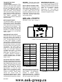
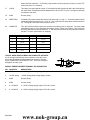
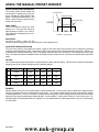
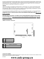
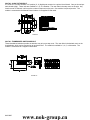
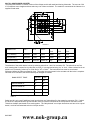
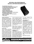
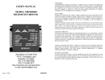
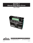
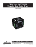
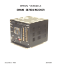
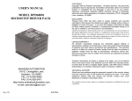
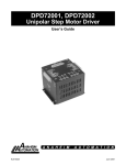
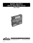
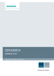
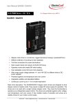
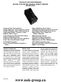
DPFHP451 HIGH PERFORMANCE
BILEVEL STEP MOTOR / MANUAL PRESET INDEXER
DRIVER PACK
! Internal Index Count switches
! Pulse Rates up to 14,792 pulses per second
! CW & CCW Home, Hard, & Soft Limit Inputs
! Adjustable Motion "Complete" Output
! Motion "Busy" Output
! Clock Pulses and Step Direction Outputs
! CW and CCW Index Inputs
! CW and CCW Jog/Run and Fast Jog Inputs
! Two "Go to Home Position" modes
! TTL-MOS Compatible
! Pulse & Reset Outputs & Coincidence
Inputs
GENERAL DESCRIPTION
The Anaheim Automation DPFHP451
Step Motor Driver Pack is designed for
motor applications that require very
high power output and high start-stop
step rates. Outstanding motor
performance is achieved by means of
an enhanced bilevel or dual-voltage
drive technique. This Driver Pack
contains a high performance driver
board
(BLHP101),
a
500VA
transformer, and a dual power supply.
It may be used with six or eight lead,
size 34 and 42 step motors whose
phase current ratings range from 2 to
12.5 amperes per phase.
#L010035
!Very High Motor Power Output
!15Amps/phase Maximum Operating Current
!10 Amps/phase Standstill motor current
!Dual Voltage Power Supply with
500VA Transformer
!High Start-Stop Speeds
!Transient Voltage Suppression
!Halfstep and Fullstep Operation
!Bilevel Drive (No RFI or EMI problems)
!TTL/CMOS Compatible Inputs
!Clockand Direction or Dual Clock Operation
!Motor Turn-off Input
BILEVEL DRIVE
The basic function of a step motor
driver is to control the motor winding
currents. Motor performance is
determined by how fast the driver can
increase and decrease the winding
currents. A rapid rise in winding
current is achieved by applying a high
voltage directly to a motor. This rapid
rise of current is also referred to as
the "kick" or operating current. When
a desired current level is reached, a
low voltage is applied to maintain a
suitable holding current level. When a
motor winding is turned off, a rapid
decrease in winding current is
achieved by routing the energy in the
collapsing field back to the power
supply through a high voltage path.
The high voltage supply furnishes the
energy necessary to maintain motor
output torque at high step rates thus
providing high mechanical power
output.
The low voltage supply
provides much of the current needed
at low step rates and all of the holding
current.
Bilevel drivers do not use high
frequency switching techniques as
chopper drivers do. Consequently,
they do not create the EMI, RFI, and
motor heating problems that are
associated with chopper drivers.
www.nok-group.cn
TRANSIENT VOLTAGE
SUPPRESSION
Transient Voltage Suppression (TVS)
Diodes on the motor phase outputs
allow for much longer motor cables to
be used. Normally when using long
motor cables, voltage transients and
spikes are created. These transients
often exceed the voltage ratings of the
output phase transistors, resulting in
blown transistors. The addition of the
TVS Diodes suppresses these
transients and protect the transistors
against damage.
MOTOR ON/OFF INPUT
The MOTOR ON/OFF input can be
used to turn off all four motor phases
(de-energize the motor) in applications
where motor detent torque is sufficient
to maintain the load position. This
feature can be used to reduce the load
on the power supply and the heat
dissipation in the driver circuitry and
motor. Terminal 10 is the MOTOR
ON/OFF Input.
MODE SELECT/+5V OUTPUT
DPFHP001 Driver Packs are shipped
from the factory with terminal 9
assigned as an excitation Mode Select
input. The Mode Select input is used
to select either halfstep or fullstep
motor operation. Halfstep operation is
generally preferred because this mode
provides better resolution, minimizes
resonance effects, and reduces power
consumption. The motor steps in
increments of half the natural step
angle, e.g. in 0.9 degree steps for a
1.8 degree step motor. In fullstep
operation, the motor steps in 1.8
degree steps. By setting JP2 to the "12" position, terminal 9 becomes a
+5VDC regulated output. The driver
defaults to halfstep when the +5VDC
output is used.
ADJUSTING THE KICK CURRENT
The kick (or operating) current level is
the desired phase current level that the
high voltage provides each time a step
is taken. The high voltage is turned off
when this level is reached. The kick
current level should be set to
approximately 1.4 times the rated
phase current. For example, a motor
rated at 10 amps/phase should be
"kicked" to 14 amps. Table 2 shows
various kick current levels for
corresponding phase currents. When
using a motor listed in Table 3, use the
recommended potentiometer setting.
#L010035
WARNING: The kick current level
must be set before operating a motor.
MOTOR DRIVER CONNECTIONS
Motor wires are connected to the
driver pack through terminals 1, 2, 3,
12, 13, and 14. Electrical connections
to control inputs should be kept
physically separated from the motor
connections. Wiring from the driver
to the motor should be routed away
from all other wiring.
MOUNTING AND COOLING
The DPFHP451 contains an internal
fan to create airflow through the unit.
Heating considerations should include
where the unit is mounted, the duty
cycle
of
operation,
ambient
temperature, etc. Care should be
taken so that no point on the chassis
exceeds 60 degrees Celcius.
OTHER HIGH PERFORMANCE
DRIVER PACKS are available. The
DPFHP451 Driver Pack includes a
FIGURE 1: Jumper and Connector Locations
Rated Motor
Phase Current
KICK
CURRENT
1.4 - 2.4
2.0 - 3.4
2.4 - 3.3
3.4 - 4.6
3.3 - 4.3
4.6 - 6.0
4.3 - 5.4
6.0 - 7.5
5.4 - 6.3
7.5 - 8.8
6.3 - 7.2
8.8 - 10.1
7.2 - 8.1
10.1 - 11.4
8.1 - 8.9
11.4 - 12.5
8.9 - 9.6
12.5 - 13.5
9.6 - 12.5
13.5 - 15.0
Table 1: Potentiometer Settings for
Kick Current
AA MOTOR
HOLDING
CURRENT
KICK
CURRENT
34D106
1.95 - 3.00
4.20
34D109
3.12 - 4.80
6.72
34D207
2.28 - 3.50
4.90
34D209
3.00 - 4.60
6.44
34D213
4.23 - 6.50
9.10
34D307
2.28 - 3.50
4.90
34D311
3.58 - 5.50
7.70
34D314
4.55 - 7.00
9.80
42D112
3.97 - 6.10
8.54
42D119
6.18 - 9.50
13.3
42D212
3.97 - 6.10
8.54
42D219
5.98 - 9.20
12.88
PI45 Preset Indexer along with the
42D225
8.25 - 10.00
15.00
bilevel high performance driver and TABLE 2 Holding Current and Kick Current Settings
power supply. The DPFHP401
for AA Motors
includes
a
SMC40
based
Programmable Indexer. All DPFHP
Series Driver Packs are available in
250 VAC versions (add "X250" suffix).
www.nok-group.cn
TORQUE/SPEED CURVES
FIGURE3: Dimentions
#L010035
www.nok-group.cn
INDEXER DESCRIPTION AND FUNCTION
MANUAL PRESET INDEXER BOARD
The Manual Preset Indexer board utilizes the PI45 Preset Indexer integrated circuit (I.C.). Functions available are Home,
Hard and Soft Limit inputs, two Homing modes, Jog/Run, Fast Jog and switch selectable Base Speed, Maximum Speed,
Acceleration/Deceleration.
This board includes the necessary buffering and other circuitry for the PI45 chip that makes indexing easy. The board can
be operated manually or with a Programmable Logic Controller (PLC) to index a set of pulses determined by the internal
count switches or an external count module, such as the AA1760-5 or similar device.
MANUAL PRESET INDEXER TERMINAL (P1) DESCRIPTION
PIN
1
FUNCTION
-HARD LIMIT
DESCRIPTION
When active low, this signal instructs the step motor to halt all motion in CCW direction.
2
+HARD LIMIT Same as -HARD LIMIT except in CW direction.
3
-SOFT LIMIT
When active low, this signal instructs the step motor to ramp down to base speed and complete the
move. Input active during a -Index or -Home function.
4
+SOFT LIMIT
Same as -SOFT LIMIT except in CW direction.
5
-HOME LIMIT Used in H0 Homing mode in conjunction with -Soft Limit. Giving -Home command (active low)
causes motor to ramp to high speed in the CCW direction until -Soft Limit is contacted. At contact,
motor will decelerate to base speed and run until the -Home Limit is contacted, at which time the
motor will stop.
6
+HOME LIMIT Same as -HOME LIMIT except in CW direction.
7
-JOG/RUN
A low level on this line causes the step motor to take one step in the CCW direction. Normally, the
JOG/RUN inputs are manipulated by external pushbutton switches. A single depression of the
switch causes a "jog" operation, while holding the switch down for 0.5 seconds causes a "slow run"
condition. This command may be used with FAST to perform a fast run at the base speed rate.
8
+JOG/RUN
Same as -JOG/RUN except in CW direction.
9
-HOME
A low level on this line instructs the step motor to move to the home position via the CCW
direction. (See HOME SELECT)
10
+HOME
Same as -HOME except in CW direction.
11
-INDEX
When low, this signal causes the PI45 chip to read the current motion parameters and number of
steps from the thumbwheel switches and command the motor to step the indicated distance in the
CCW direction. (See -SOFT LIMIT). NOTE : If -SOFT LIMIT is encountered during an Index, the
motor will decelerate to base speed and complete the Index.
12
+INDEX
Same as -INDEX, but commands a CW step motion.
13
#INT/EXT
This input determines which set of switches will be used for counting. A logic “1" or open selects the
Internal Index Count Number. A logic “0" selects the count of an external counter module.
14
HOME SELECT This input selects the type of "Home" operation to perform: When active low, H0 Homing Mode is
selected. It is a standard deceleration and stop on switch operation. In essence, type H0 is a
combination of the HOME and SOFT limit commands. When active high, H1 Homing Mode is
selected. H1 is used for anti-backlash protection. It performs a decelerate, reverse, return off switch
operation. NOTE: the switch must remain closed during deceleration, reverse, and return in H1
Mode.
15
FAST
16
BUSY
#L010035
When active low, it is used in conjunction with JOG/RUN to cause a fast run (base speed) operation
in the specified direction.
This open collector switch output is ON when the motor is moving. This output can sink 0.5A and
www.nok-group.cn
stand off 40Vdc maximum. A 10k ohm pullup resistor can be jumpered in place to provide TTL
levels (see section on Jumpers).
17
CLOCK
This output is an open collector output, 15 microseconds wide (minimum) that is the clock input for
the motor driver. It is buffered to assure adequate drive for an LS-TTL input. This signal is internally
connected to the driver.
18
0VDC
Ground (0Vdc).
19
DIRECTION
Clockwise (CW) motion causes this output to be active high i.e. logic “1". Counterclockwise motion
causes this output to be active low i.e. logic “0". This output tells the motor driver which direction to
run. This signal is internally connected to the driver.
20
COMPLETE
This open collector switch output turns on after the indexing cycle is executed. The pulse width
(time that this output is on) is adjustable from about 12ms to 120ms (see Table 3). This output can
sink 0.5A and stand off 40Vdc maximum. A 10k ohm pullup resistor can be jumpered in place to
provide TTL levels. (see section on Jumpers).
SETTING
PULSE WIDTH
SETTING
PULSE WIDTH
1
12 ms
6
79.5 ms
2
25.5 ms
7
93 ms
3
39 ms
8
106.5 ms
4
52.5 ms
9
120 ms
5
66 ms
--
--
TABLE 3: Pulse Width Settings
TYPICAL HOOK-UPS FOR BUSY AND COMPLETE OUTPUTS:
K1 will energize immediately after completion of an index cycle
and remain energized for approximately an amount of time set
by the “COMPLETE PULSE WIDTH” POT. K2 will be energized
throughout an index cycle.
MANUAL PRESET INDEXER TERMINAL (P2) DESCRIPTION
FIGURE 4
PIN
1
FUNCTION
+5VDC
DESCRIPTION
+5VDC Regulated Voltage Supply Output
2
+12VDC Unreg
+12VDC Unregulated Voltage Supply Output
3
0VDC
Ground (0Vdc).
4
0VDC
Ground (0Vdc).
5
9 - 12VAC IN
9 - 12VAC Voltage Supply Input for PCL451 version.
6
9 - 12VAC IN
9 - 12VAC Voltage Supply Input for PCL451 version.
#L010035
www.nok-group.cn
USING THE MANUAL PRESET INDEXER
SELECTING MOTION PARAMETERS
The velocity profile (motion speed and
acceleration) is determined by the four
green switches; the Base Speed, Max
Speed, Acceleration/Deceleration, and
Factor. Figure 5 shows a typical velocity
profile of a step motor.
ACCELERATION
MAXIMUM SPEED
DECELERATION
SPEED
BASE SPEED
This is the speed at which the motor
starts to run. There are 256 choices of
Base Speeds as shown in the Table 6.
They range from 2 steps/second to 3,611
steps/second.
BASE SPEED
TIME
FIGURE 5: Velocity Profile
MAX SPEED
As shown in Table 5, there are 256
choices available ranging from 163 steps/second to 14792 steps/second.
ACCELERATION/DECELERATION
The step motor starts to accelerate after taking 4 steps at the base speed and continues until it reaches the selected
maximum speed taking the number of steps set by A/D at each speed in the internally generated ramp table. A/D=0 is no
acceleration (run at BASE speed only), A/D=1 is the fastest (minimum ramp time), and A/D=F is the slowest (maximum ramp
time). The step motor starts to decelerate at the calculated point and continues until it reaches the selected base speed and
stops.
FACTOR
The F switch should be set first because it directly affects the Base and Max speed. Table 4 lists the maximum obtainable
stepping rates for all F switch settings with the maximum speed F.
F
Max(steps/sec)
F
Max
F
Max
F
Max
0
14792
4
4930
8
2548
C
728
1
9264
5
4266
9
1816
D
484
2
7165
6
3759
A
1411
E
366
3
5841
7
3360
B
946
F
246
TABLE 4: Maximum Rates for Factor Settings
EXAMPLE
Assume that the motor is to run at a Max Speed of 4500 steps/second. It can be seen from the table above that this speed
can only be obtained with the F switch setting of 0 through 4. Any of these switch settings could provide speeds in excess
of 4500 steps/second. The 'rule of thumb' is to always chose the highest F switch setting that will provide the desired Max
Speed, and also give the widest range for Base Speeds. In this example, F with a switch setting of 4 is the best choice. For
a desired speed of 1200 steps/second, set F switch to A. For a desired speed of 13000 steps/second, only an F switch setting
of 0 will suffice.
#L010035
www.nok-group.cn
SETTING THE M SWITCH
Now that we have selected the F switch setting, we can find the value for M from Table 5. The factor setting is in the left
hand column, and the Max Speed setting is along the top row. In example 1 for the desired M of 4500 steps/second, we set
the F switch at 4. Table 4 lists the maximum speed values for each switch setting of F. Looking at the M values in Table
5 for an F switch setting of 4, the closest speeds are 4495 (M=C) and 4631 (M = D). For the desired maximum speed of 1200
steps/second (F=A) and M switch setting of 9 (1173 sps) or A (1207 sps) can be used. A speed of 13000 sps (F=0) requires
an M switch setting of either A (12737 sps) or B (13102 sps).
M SWITCH SETTING
F
0
163
1
166
2
170
3
174
4
179
5
183
6
188
7
193
8
199
9
204
A
210
B
217
C
223
D
231
E
238
F
246
E
242
248
253
259
266
272
279
287
295
303
313
322
332
342
354
366
D
320
327
335
342
351
360
369
380
390
401
412
425
438
452
467
484
C
481
493
504
517
529
543
557
572
588
604
623
641
661
682
705
728
B
626
641
656
672
689
706
725
744
764
786
809
833
859
886
915
946
A
936
957
980
1004
1028
1054
1082
1111
1141
1173
1207
1242
1281
1322
1365
1411
9
1207
1234
1263
1293
1325
1358
1394
1431
1470
1511
1544
1601
1650
1702
1757
1816
8
1699
1737
1777
1820
1864
1911
1959
2011
2066
2123
2184
2248
2316
2388
2466
2548
7
2248
2298
2351
2407
2466
2526
2591
2658
2730
2805
2884
2968
3057
3152
3252
3360
6
2520
2576
2635
2697
2762
2830
2902
2977
3057
3141
3229
3323
3422
3527
3640
3759
5
2866
2930
2997
3067
3141
3218
3299
3384
3474
3568
3669
3774
3886
4005
4132
4266
4
3322
3397
3474
3554
3639
3728
3821
3919
4022
4132
4246
4367
4495
4631
4777
4930
3
3953
4040
4131
4227
4326
4431
4540
4655
4777
4904
5039
5181
5332
5491
5661
5841
2
4878
4985
5095
5211
5332
5459
5592
5732
5879
6033
6196
6368
6551
6743
6948
7165
1
6369
6504
6646
6793
6948
7110
7279
7456
7642
7838
8045
8263
8492
8734
8991
9264
0
9968 10190 10422 10664 10918 11185 11464 11758 12067 12393 12737 13102 13487 13895 14330 14792
TABLE 5: Max Speed (Factor Setting vs. Max Setting)
SETTING THE B SWITCH
#L010035
www.nok-group.cn
By choosing an F value, we restrict our choice of Base Speed to 16 possible values (see Table 6). In example 1, from
maximum speed of 4500 steps/second (F = 4) we can select Base speeds ranging from 42 to 1223 steps/second. For the
desired maximum speed of 1200 sps (F=A), the Base speed can be chosen from a range of 11 sps to 339 sps. If due to the
selection of the factor we are limited to a low Base Speed, it is possible to choose a lower Factor and then choose the
appropriate Base and Max settings. Thus, for maximum speed of 1200 sps, a Factor of 9 could also be used, giving the
range of Base Speed 15 to 438 sps.
B SWITCH SETTING
F
0
2
1
5
2
10
3
15
4
19
5
24
6
27
7
32
8
37
9
40
A
44
B
47
C
50
D
53
E
56
F
59
E
3
7
14
22
29
36
41
48
54
60
65
71
75
79
83
87
D
4
10
19
28
38
48
54
64
72
79
86
93
99
105
110
115
C
6
14
29
43
57
72
81
97
109
120
130
141
150
159
166
174
B
8
19
37
56
75
94
106
126
141
157
170
183
195
207
216
227
A
11
28
56
84
112
140
159
189
212
234
254
274
292
309
324
339
9
15
37
73
109
145
181
205
244
274
303
329
355
377
399
418
438
8
21
52
103
154
205
256
290
349
387
428
464
501
533
564
590
619
7
28
69
138
206
273
341
386
459
515
569
618
666
707
749
784
821
6
31
78
155
231
307
383
434
516
578
640
694
748
795
841
880
922
5
35
89
177
264
350
438
495
589
659
730
791
853
906
959
1003
1052
4
42
104
206
308
408
510
577
686
768
849
921
993
1054
1116
1167
1223
3
50
124
247
370
489
610
690
821
919
1015
1101
1187
1260
1333
1394
1460
2
62
154
309
460
610
761
860
1021
1143
1264
1368
1474
1565
1655
1730 1812
1
83
206
411
612
809
1009
1141
1352
1513
1671
1809
1947
2066
2181
2281 2389
0
124
310
617
919
1216 1519
1717
2038
2282
2520
2730
2939
3120
2957
3448 3611
TABLE 6: Base Speed (Factor Setting vs. Base Setting)
#L010035
www.nok-group.cn
HOMING MODES
There are two Homing Modes that may be initiated, H0 and H1.
H0 HOMING MODE
This mode causes the motor to run at Max Speed in the direction selected. The motor runs until the nut encounters the
SOFT limit switch, at which time the motor decelerates to the Base Speed. The nut continues to run at Base Speed until
it hits the Home limit switch. This may be illustrated by using a step motor driving a leadscrew as shown below.
CAUTION: The two limit switches should be placed such that the nut after hitting the Soft limit switch has enough time to
get to Base Speed before encountering the Home limit switch.
FIGURE 6: H0 Homing Mode
H1 HOMING MODE
When this homing mode is selected, the nut seeks home at Max speed. It decelerates to Base speed when the soft limit
switch is encountered. The Soft limit switch must remain closed until the motor completely decelerates to Base speed, at
which time the controller causes the motor to reverse direction and run at Base speed until the Soft limit switch is no
longer closed. This mode is illustrated below. This Homing mode uses only one switch, but a flag is required to keep the
switch closed during the deceleration cycle. If only a momentary switch closure is made, the motor will decelerate to
Base speed and stop. This stopping point may not be accurate or repeatable; so, the flag is necessary.
Figure 7: H1 Homing Mode
SETTING THE MOVE DISTANCE
The index count or move distance for the DPFHP451 can be accomplished by a number of methods. The easiest way is
#L010035
www.nok-group.cn
to use the red switches labeled “Internal Index Number” on the unit; these switches are used by default. External Count
Modules may also be used. These include the Click Pot Module, AA1748, the Thumbwheel Module, AA1760, the BCD
Input Module, AA2210, and the Quad Board, AA1754. These modules set the distance of the move, but will allow for
different variations in interfacing (see descriptions in next section).
JUMPERS
There are four jumpers on the Manual Preset Indexer board. The first jumper, JP1, is used to set the debounce delay
time for the JOG, HOME, and INDEX inputs. When JP1 is in the “1-2" position, the debounce delay is approximately
12.5 milliseconds. When JP1 is in the “2-3" position, the debounce delay is approximately 0.3 milliseconds. The active
low signal on these inputs must be wider than the debounce delay time.
To use an external Count Module, the INT/EXT input (pin 13) must be pulled low to a logic “0". The on-board switches
will be ignored. External Count Modules plug into either connector labeled “EXTERNAL COUNT MODULE
CONNECTOR”(P1 or P2). When only using one module for both FORWARD and REVERSE indexes, jumper JP2 must
be in the “1-2" position.
When using external Count Modules, it is possible to use one module for FORWARD indexing and another module for
REVERSE indexing. The connector on the side of the unit is the FORWARD count; the connector on the top (of front
face) is the REVERSE count. When using two modules for different FORWARD and REVERSE indexes, jumper JP2
must be in the “2-3" position.
JUMPER LOCATIONS / FUNCTIONS
FIGURE 8
JP1
DEBOUNCE INPUT DELAY
1-2
12.5 ms
2-3
0.3 ms
TABLE 7
JP2
EXTERNAL COUNT MODULES
1-2
ONE MODULE (SAME FORWARD AND REVERSE)
2-3
SEPARATE MODULES FOR FORWARD AND REVERSE
TABLE 8
COUNT INPUT BOARDS
All of the Count Input Boards or Modules set the number of steps the motor will move when an Index is initiated, but each
Module allows for a different variation in interfacing.
#L010035
www.nok-group.cn
AA1748 - CLICK POT MODULE
A 'CLICK POT' module consists of 10 position (0 - 9) digital pots mounted on a printed circuit board. One pot is used per
each decade (digit). These units are available in 2, 4, or 6 decades. The user dials in the step count on the pots. Any
time the motor is indexed, it will move the number of steps set on the pots. One module is required per axis. The
module is connected to the Manual Preset Indexer via a supplied 5 lead cable.
FIGURE 9
AA1760 - THUMBWHEEL SWITCH MODULE
These thumbwheel switches provide an attractive way to input a step count. The user dials in the desired count on the
thumbwheels, which can be mounted on an enclosure face. The module is available in 3, 4, 5, or 6 decades. The
module is connected via a supplied 5-lead cable.
FIGURE 10
#L010035
www.nok-group.cn
AA1754 - QUAD BOARD COUNTER
The quad board module is a 4-bank version of the clickpot module with each bank having 6 decades. The user can "dial
in" four different move lengths and then select any one of them as desired. The module is connected to the indexer via a
supplied 5-lead cable.
FIGURE 11
CONNECTOR
Pin 1
Pin 2
Pin 3
Pin 4
Pin 5
Pin 6
P1 (To Indexer)
Common
+5Vdc
Clock
Reset
Key
0Vdc
P2 (Expansion)
Common
+5Vdc
Clock
Reset
Key
0Vdc
P3 (Select Inputs)
Select #1
Select #2
Select #4
Key
+5Vdc
0Vdc
TABLE 9
The selection of the switch banks is done by switching select lines 1 and 2 on connector P3. The select lines are "low
true" meaning that if a select line is pulled low (to 0Vdc), it is recognized as being "on" or "true". When a select line is not
pulled low it is internally "pulled up" to +5Vdc and is "off" or "false". The bank select lines must be set at least 1
millisecond before the Index command is given. The select lines must remain in the set state until the index is complete.
Once the move is finished, the select lines may be changed as needed.
BANK SELECT TABLE
SELECT
LINE
#1
#2
SWITCH BANK #1
0
0
SWITCH BANK #2
1
0
SWITCH BANK #3
0
1
SWITCH BANK #4
1
0 = Low 0 - .8Vdc 1= High 3.5 - 5Vdc
1
TABLE 10
Select line #4 is only used if additional count input devices are "daisychained" to the expansion connector (P2). If select
line #4 is low, that quad board is ignored and the count input device connected to the P2 expansion connector is read.
This allows multiple quad boards to be used together. The "daisychained" count input device does not have to be a quad
board; it could be a thumbwheel switch or click pot module.
#L010035
www.nok-group.cn
AA2210 BCD COUNTER MODULE
The AA2210 BCD counter interface module enables the user to select any move length from 0 to 999,999 steps using a
standard PLC (programmable logic controller). Selecting the proper inputs creates a count value in steps, resulting in a
move distance. The module is connected to the indexer via a supplied 5-lead cable.
Note: All Inputs are active low (0-0.8Vdc). All unused inputs may be ignored since they are pulled up.
Example: For a move distance of 1234 steps the following inputs should be pulled low.
1's Decade: Bit 4 (TB1, pin 4)
10's Decade: Bit 1 and 2 (TB2, pin 2 and 3)
100's Decade: Bit 2 (TB1, pin 7)
1000's Decade: Bit 1 (TB2, pin 6)
All Other inputs must be open or high (3.5-5Vdc).
FIGURE 12
#L010035
www.nok-group.cn
SPECIFICATIONS
CONTROLER INPUTS:
TTL-MOS Compatible
Logic "0": 0 to 0.8 Vdc
Logic "1": 3.5 to 5 Vdc
+5VDC
1K
INPUT
All Input Terminals are pulled up to +5Vdc through 1k ohm resistors.
10K
CMOS
220pF
Busy and Complete Outputs (pins 16 and 20) are open collector outputs that can sink 500mA and stand-off 40Vdc maximum
(no sourcing). Pull-up resistors may be jumpered to these outputs to produce TTL level signals (see section on jumpers).
Ground (pin 18) - 0Vdc
+5Vdc Output (TB2, pin 1) - Up to 250mA is available for the user to power up external circuitry. The total current drawn from
pin 1 and pin 2 must not exceed 250mA.
+12Vdc Unregulated Output (TB2, pin 2) - Up to 250mA is available for the user to power up external circuitry. The total
current drawn from pin 1 and pin 2 must not exceed 1.0A.
DRIVER INPUTS:
Terminals 5,6,9,10
Logic "0": 0 to 0.8 VDC.
Logic "1": 3.5 to 5 VDC.
POWER REQUIREMENT
105 VAC to 125 VAC for DPFHP451
210 VAC to 250 VAC for DPFHP451x250
MODE SELECT
When programmed as Mode Select Input (set by JP2), this terminal is internally pulled up to +5VDC through a 10k ohm
resistor. When a logic "1" (or no connection) is applied, the motor will operate in halfstep mode. When a logic "0" is
applied, the motor will operate in fullstep mode.
MOTOR ON/OFF INPUT
This terminal is internally pulled up to +5VDC through a 10k ohm resistor. When a logic "1" (or no connection) is applied,
the driver phase outputs are enabled and the motor is energized. When a logic "0" is applied, the driver phase outputs
are disabled and the motor is de-energized.
MOTOR PHASE OUTPUTS: (Terminals 1,2,13,14)
These outputs can sink a peak of 15 Amperes or sink 10 Amperes continuously and stand-off 250 VDC maximum.
MOTOR COMMON OUTPUTS: (Terminals 3,12)
These outputs can source a peak current of 15 Amperes, or source 10 Amperes continuously.
AMBIENT TEMPERATURE: 0 to 50 degrees Celsius.
SHIPPING WEIGHT: 15 pounds
#L010035
www.nok-group.cn
Notes:
#L010035
www.nok-group.cn
www.nok-group.cn