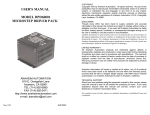
1
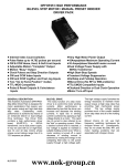
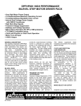
COPYRIGHT
USER'S MANUAL
Copyright 1996 by Anaheim Automation. All rights reserved. No part of this
publication may be reproduced, transmitted, transcribed, stored in a retrieval system,
or translated into any language, in any form or by any means, electronic, mechanical,
magnetic, optical, chemical, manual, or otherwise, without the prior written permission
of Anaheim Automation, 910 E. Orangefair Lane, Anaheim, CA 92801. The only
exception to this would be use of the program examples in this manual.
MODEL MDM10001
MICROSTEP DRIVER
DISCLAIMER
Though every effort has been made to supply complete and accurate information in this
manual, the contents are subject to change without notice or obligation to inform the
buyer. In no event will Anaheim Automation be liable for direct, indirect, special,
incidental, or consequential damages arising out of the use or inability to use the
product or documentation.
Anaheim Automation’s general policy does not recommend the use of its products in
life support applications wherein a failure or malfunction of the product may directly
threaten
life or injury. Per Anaheim Automation’s Terms and Conditions of Sales, the user of
Anaheim Automation products in life support applications assumes all risks of such use
and indemnifies Anaheim Automation against all damages.
LIMITED WARRANTY
All Anaheim Automation products are warranted against defects in workmanship,
materials and construction, when used under Normal Operating Conditions and when
used in accordance with specifications. This warranty shall be in effect for a period of
twelve months from the date of purchase or eighteen months from the date of
manufacture, whichever comes first. Warranty provisions may be voided if the
products are subjected to physical damage or abuse.
Anaheim Automation will repair or replace at its option, any of its products which have
been found to be defective and are within the warranty period, provided that the item
is shipped freight prepaid, with RMA (return material authorization), to Anaheim
Automation's plant in Anaheim, California.
ANAHEIM AUTOMATION
910 E. ORANGEFAIR LANE
ANAHEIM, CA 92801
(714) 992-6990
FAX (714) 992-0471
E-MAIL: [email protected]
May 21, 2002
TRADEMARKS
Control Link and Driver Pack are registered trademarks of Anaheim Automation.
#L010069
TABLE OF CONTENTS
INTRODUCTION
ORDERING INFORMATION . . . . . . . . . . . . . . . . . . . . . . . . . . . . . . . 3
The MDM10001 is a High Performance , low cost microstepping driver that
incorporates advanced surface mount and ASIC technology. The MDM10001 is
compact, easy to interface, and powerful enough to handle the most demanding
applications. Anaheim Automation recognizes that cost and size are important criteria
in many low and medium power application. The MDM10001 was designed to meet
those needs along, and offers innovative features.
DESCRIPTION . . . . . . . . . . . . . . . . . . . . . . . . . . . . . . . . . . . . . . . . . .
DRIVER TERMINAL DESCRIPTION P1 . . . . . . . . . . . . . . .
DRIVER TERMINAL DESCRIPTION P2 . . . . . . . . . . . . . . .
WIRING DIAGRAM . . . . . . . . . . . . . . . . . . . . . . . . . . . . . . . .
SPECIFICATIONS . . . . . . . . . . . . . . . . . . . . . . . . . . . . . . . . .
4
4
5
6
7
The MDM10001 will deliver a peak current of 10 Amperes per phase at 80 Volts,
providing outstanding motor performance. This advanced technology reduces ripple
current while maintaining the 20kHz chopping frequency in the motor, causing less
heat in both the motor and drive. In many cases, no special or additional heatsink is
required.
OUTPUT CURRENT . . . . . . . . . . . . . . . . . . . . . . . . . . . . . . . . . . . . . . 8
DETERMINING OUTPUT CURRENT . . . . . . . . . . . . . . . . . . 8
SETTING OUPUT CURRENT . . . . . . . . . . . . . . . . . . . . . . . . 8
RESISTOR TABLE . . . . . . . . . . . . . . . . . . . . . . . . . . . . . . . . . 9
REDUCING OUTPUT CURRENT . . . . . . . . . . . . . . . . . . . . 10
POWER CONNECTIONS . . . . . . . . . . . . . . . . . . . . . . . . . . . . . . . . . . 13
With the MDM10001, various step resolutions can be implemented by grounding the
appropriate select pin. These divisions range from 400 steps per revolution to 51,200
steps per revolution, and are available in both binary and decimal numbers. The
MDM10001 allows the number of microsteps to be changed per step at any time.
There is no need to reset the driver. The bipolar drive configuration handles 4, 6, and
8 lead motors. Protection devices have been added to this driver for Any-Way-ShortCircuit and Excessive-Temperature, and Over/Under Voltage conditions. If an error
(short-circuit or excessive-temperature) occurs, a ‘Fault Output’ can be used to
inform the machine control of a problem. An ‘At Full Step’ output enables the control
to know when the motor is positioned in one of the natural step angles of the motor
(typically every 1.8°).
ANAHEIM AUTOMATION MOTORS . . . . . . . . . . . . . . . . . . . . . . . 14
Driver features include:
MICROSTEP SELECTION . . . . . . . . . . . . . . . . . . . . . . . . . . . . . . . . 15
#
#
#
#
#
#
#
#
#
#
#
PAGE
INTRODUCTION . . . . . . . . . . . . . . . . . . . . . . . . . . . . . . . . . . . . . . . . . 2
MOTOR SELECTION . . . . . . . . . . . . . . . . . . . . . . . . . . . . . . . . . . . . 10
STEP MOTOR CONFIGURATION . . . . . . . . . . . . . . . . . . . 11
STEP MOTOR CONNECTION . . . . . . . . . . . . . . . . . . . . . . . 12
FULLSTEP OUTPUT SIGNAL . . . . . . . . . . . . . . . . . . . . . . . . . . . . . 16
OPTICALLY ISOLATED INPUTS
. . . . . . . . . . . . . . . . . . . . . . . . . 16
TIMING . . . . . . . . . . . . . . . . . . . . . . . . . . . . . . . . . . . . . . . . . . . . . . . 17
FAULT PROTECTION . . . . . . . . . . . . . . . . . . . . . . . . . . . . . . . . . . . . 18
TORQUE/SPEED CURVES . . . . . . . . . . . . . . . . . . . . . . . . . . . . . . . . 19
1
Low Cost
Small Size (3"x 6"x 1¼)
Input Voltage 24 to 80VDC
Output Current 10 Amps Peak
400 to 51,200 steps/rev
Short Circuit Protection
Excessive-Temperature Protection
No Minimum Inductance
Optical Isolation
Fault Output
Over/Under Voltage
2
PIN DESCRIPTIONS P1
ORDERING INFORMATION FOR ANAHEIM AUTOMATION
MICROSTEP DRIVERS AND ACCESSORIES
Pin#
1-4
4 Amp Microstep Driver
6 Amp Microstep Driver
10 Amp Microstep Driver
Manual)
40VDC Power Supply
65VDC Power Supply
80VDC Power Supply
Description
Microstep Select Inputs (1-4): These inputs select the number of
microsteps per step. They are optically isolated binary encoded inputs.
MDM40001
MDM60001
MDM10001 (This
5
PSA40V4A
PSA65V5A
PSA80V4A
+5 VDC: This input is used to supply current to the Isolated Inputs. A
higher voltage may be used, but care should be taken to limit the current
through the optocoupler.
6
Step Clock Input: A positive going edge on this isolated input advances
the motor one increment. The size of the increment is dependent on the
Microstep Select Inputs of Connector P1.
7
Direction: This isolated input is used to change the direction of the motor.
Physical direction also depends on the connection of the motor windings.
8
MDM60001
This is the model number for a Single Axis, 6 Amp Microstep Driver. MDM60001
requires a 65Vdc power supply (PSA65V5A) that Anaheim Automation provides,
purchased separately.
Reset: When LOW, this isolated input will reset the driver (outputs will
disable). When released, the driver will be at its initial state (Phase A off,
Phase B full on).
9
MDM10001
This is the model number for a Single Axis, 10 Amp Microstep Driver. The
MDM10001 requires an 80Vdc power supply (PSA80V4A) that Anaheim Automation
provides, purchased separately.
ON/OFF: This isolated input is used to enable/disable the output section of
the driver. When HIGH (open) the outputs are enabled. However, this input
does not inhibit the step clock. Therefore when enabled, the outputs will be
updated by the number of clock pulses (if any) applied to the driver while it
had been disabled.
10
MDM40001
This is the model number for a Single Axis, 4 Amp Microstep Driver. The
MDM40001 requires a dc power supply (up to 40 volts). The PSA40V4A is the
recommended power supply that Anaheim Automation supplies.
PSA40V4A
This is an unregulated 40VDC, 4A power supply.
Current Reduction: This isolated input is used to switch in and out the
Current Reduction Resistor connected to Connector P2 Pins 3 and 4. When
this input is LOW the Reduction Resistor is switched in.
Table 1 - CONNECTOR P1
PSA65V5A
This is an unregulated 65VDC, 5A power supply.
PSA80V4A
This is an unregulated 80VDC, 4A power supply.
3
4
TYPICAL HOOK-UPS FOR APPLICATION:
FIGURE 1
PIN DESCRIPTIONS P2
Pin#
Description
1
Fullstep: This OPEN DRAIN output indicates when the driver is
positioned at a full step. This output can be used to count the number of
full steps the motor has moved, regardless of the number of microsteps
in between. This output is active low.
2
Fault: This OPEN DRAIN output indicates a fault has occurred (ie.
short circuit or over temperature). This output is active low.
3
Reduction Adjust: Phase Current Reduction Input. A resistor between
this pin and pin 4 (Connector P2, Current Adjust) will proportionately
reduced the current in both windings (when selected by pin 10
Connector P1 or approximately 1 second after the last positive going
edge of the step clock input). The amount of current reduction will
depend on the value of the resistor used.
4
Current Adjust: Phase Current Adjustment input. A resistor connected
between this input and the ground input (connector P2, Pin 5) is used to
adjust the maximum phase current in the motor. A resistor MUST be
connected to this input.
5
Ground: Supply Voltage Ground. ( Return )
6
+V: Supply Voltage Input. (+24 - 80VDC)
7
Phase 4 of the Step Motor
8
Phase 3 of the Step Motor
9
Phase 2 of the Step Motor
10
Phase 1of the Step Motor
Table 2 - CONNECTOR P2
5
6
SPECIFICATIONS
DETERMINING OUTPUT CURRENT
ABSOLUTE MAXIMUM RATINGS
The output current for the motor used when microstepping is determined differently
from that of a half/full unipolar driver. In the MDM10001, a sine/cosine output
function is used in rotating the motor. The output current for a given motor is
determined by the motors current rating and the configuration for how the motor is
hooked up. There is a current adjustment resistor used to set the output current of the
MDM10001. This sets the peak output current of the sine/cosine waves. The
specified motor current (which is the RMS value) is multiplied by a factor of 0.7, 1.0,
or 1.4 depending on the motor configuration (half-coil, series, or parallel).
INPUT VOLTAGE
+24 TO +80 VDC
OUTPUT CURRENT
10 AMPS PEAK
PLATE TEMPERATURE
70° C
STORAGE TEMPERATURE
40° TO +125° C
INPUT CURRENT (PINS 1, 2, 3, 4, 6, 7, 8, 9, 10)
15 mA Max
OPERATING TEMPERATURE
0 TO +50° C
SETTING OUTPUT CURRENT
ELECTRICAL SPECIFICATIONS (TA=25°C, V+ = 80VDC)
ITEM
TEST CONDITION
Input Voltage
Phase Output Current
RMS
Phase Output Current
Peak
Quiescent Current
Active Power
Dissipation
Input Forward Current
MIN
TYP
MAX
UNITS
24
80
80
V
7
A
10
A
2
Outputs Floating
85
Iout=7 Amps RMS
Input Pins
1, 2 ,3, 4, 6, 7, 8, 9,10
Input Forward Voltage
Input Reverse
Breakdown Voltage
Output Current
19
W
7
15
mA
1.5
1.7
V
5
V
25
mA
Collector-Emitter
Voltage
Fault Output
140
V
Collector-Emitter
Saturation Voltage
Fault Output
Ics=25mA DC
0.2
V
Drain-Source Voltage
Fullstep Output
100
V
Fullstep Output
Ics=25mA DC
7
RMS OUTPUT CURRENT (Amps) = (0.707)(0.003)(Resistance in Ohms)
Figure1
mA
Fault, Fullstep Outputs
Drain-Source on
Resistance
TABLE 3
The output current on the MDM40001 is set by an external ±1%, 1/8 watt (or higher)
resistor between pins 2 and 3 of connector P2. This resistor determines the per Phase
RMS output current of the driver. The MDM40001 uses a 1mA current source to
establish the reference voltage needed to control the output current. The relationship
between the output current and the resistor value is as follows:
.65
ohms
8
See
RESISTOR TABLE
REDUCING OUTPUT CURRENT
RMS Current
Resistor Value
RMS Current
Resistor Value
2.0
931
4.2
2000
2.1
1000
4.4
2050
2.3
1070
4.5
2100
2.4
1130
4.7
2150
2.5
1180
4.8
2260
2.7
1270
4.9
2320
2.8
1330
5.1
2370
3.0
1400
5.2
2430
3.1
1470
5.4
2490
Reducing the output current in the MDM10001 can be accomplished by connecting an
external 1/8 watt (or higher) resistor between pins 3 and 4 of connector P2 and then
by either activating pin 10 on connector P1 or occurs automatically 1 second after the
last positive going edge of the step clock input. See Figure 1 for TYPICAL HOOK-UP.
When pin 10 on connector P1 is pulled LOW, (Active) the output current of each phase
will reduce to the value set by the current reduction resistor.
The amount of current per phase in the reduction mode is related to the value of the
current adjustment resistor and the current reduction resistor. When the current
reduction circuit is activated, the current reduction resistor is paralleled with the
current adjustment resistor. This lowers the total resistance value, and thus lowers the
per phase output current. The relationship between the output current and the resistor's
value is as follows:
Reduction Current (Amps) = .003 x .707 x *R(Current Adjust) x R(Current
3.3
1500
5.5
2610
Reduction)
3.4
1580
5.7
2670
Reduction)
3.5
1650
6.0
2800
3.7
1690
6.4
3010
3.8
1780
6.7
3160
4.0
1870
7.07
3320
R(Current Adjust) + R(Current
NOTE: When connecting the current reduction resistor between pins 3 and 4 of
connector
P2 , the length of the leads should be as short as possible to help minimize noise
coupled into the driver.
MOTOR SELECTION
4.1
TABLE 4:
1910
RESISTOR VALUES WITH RESPECT TO OUTPUT CURRENT
Closest 1% value selected
WARNING! A current adjustment resistor is always necessary to keep the drive in a
safe operating region. Do not operate the driver without a current adjustment resistor.
NOTE: When connecting the CURRENT ADJUSTMENT resistor between Pins 4 and
5 of Connector P2 the length of the leads should be as short as possible to help
minimize the noise coupled into the driver (See Figure 2).
9
The MDM10001 is a Bipolar driver which works equally well with both Bipolar and
Unipolar motors,( i.e. 8 and 4 lead motors and 6 lead center tapped motors).
Motors with low current ratings and high inductance will perform better at low speeds,
providing high low-end torque. Motors with high current ratings and low inductance
will perform better at high speeds, providing high high-end torque.
Since the MDM10001 is a constant current source, it is not necessary to use a motor
that is rated at the same voltage as the supply voltage. What is important is that the
MDM10001 is set to the appropriate current. Higher voltage will cause the current to
flow faster through the motor coils. This in turn means higher step rates can be
achieved. Care should be taken not to exceed the maximum voltage of the driver.
10
STEP MOTOR CONFIGURATIONS
Step motors can be configured as 4, 6, or 8 leads. Each configuration requires different
currents. Shown below are different lead configurations and the procedures to
determine their output current.
6 Lead Motors
When configuring a 6 lead motor in a half-coil configuration (connected from one end
of the coil to the center tap) use the specified per Phase (or unipolar) current rating to
determine the current adjustment resistor value. This configuration will provide more
torque at higher speeds. Use this to determine the current adjustment resistor value.
4 Lead Motors
Use the specified series motor current to determine the current adjustment resistor
value. Four Lead Motors are usually rated with their appropriate series current, as
opposed to the Phase Current which is the rating for 6 and 8 lead motors.
8 Lead Motors
Series Connection: When configuring the motor windings in series, multiply the per
Phase (or unipolar) current rating by 0.7. Use this result to determine the current
adjustment resistor value.
When configuring the motor in a series configuration (connected from end to end with
the center tap floating) multiply the per Phase (or unipolar) current rating by 0.7.Use
this result to determine the current adjustment resistor value.
Parallel Connection: When configuring the motor windings in parallel, multiply the
per Phase (or unipolar) current rating by 1.4. Use this result to determine the current
adjustment resistor value.
WARNING! Step motors will run hot even when configured correctly, damage may
occur to the motor if a higher than specified current is used. Most specified motor
currents are maximum values. Care should be taken to not exceed these ratings.
NOTE: After the current has been determined, according to the motor connections
above, follow the procedure Determining Output Current above to find the current
value. Then use Table 3 to choose the proper resistor value.
11
12
CONNECTING THE STEP MOTOR
Anaheim Automation Step Motor Selection Guide
Phase A of the Step Motor is connected between pins 9 and 10 on connector P2. Phase
B of the Step Motor is connected between pins 7 and 8 on connector P2.
Part Number
Motor Current
[ Amps ]
Series
Configuration
1% Resistor
Value
[ Ohms ]
(Unipolar Rating)
Refer to Figure 1 for TYPICAL APPLICATION HOOK-UP
NOTE: The physical direction of the motor with respect to the direction input will
depend on the connection of the motor windings. To reverse the direction of the motor
with respect
to the direction input, switch the wires on phase A & phase} wires pin 9 & 10.
23D104
2.0
665
23D108
3.9
1300
WARNING: Do not connect or disconnect motor wires while power is applied!
23D204
1.8
665
23D209
4.7
1540
23D306
2.9
976
23D309
4.6
1540
34D106
3.0
1000
34D109
4.8
1620
34D207
3.5
1150
34D209
4.6
1540
34D213
6.5
2150
34D307
3.5
34D311
5.5
1820
34D314
7.0
2320
42D112
6.1
2000
42D119
9.5
3160
42D212
6.1
2000
42D219
9.2
3090
CONNECTING POWER
Pins 5 and 6 on connector P2 are used to connect the DC Power Supply to the
MDM10001. Wire size used to connect the power source to the driver should be at
least 16 gauge. Heavier wire should be used for longer distances between the power
supply and the driver. The power supply requirement are as follows:
Switching Power Supplies and regulated linears with overcurrent protection are not
recommended because of their inability to handle surge currents. Adding a capacitor
to the output will alleviate this problem.
When multiple drivers are run from one power supply, each driver should have
separate power and ground wires that connect directly to the output capacitor of the
power supply.
Refer to Figure 1 for TYPICAL APPLICATION HOOK-UP.
WARNING: When using an unregulated power supply, care should be taken to ensure
that the output voltage DOES NOT exceed the maximum driver input voltage because
of line voltage fluctuations. It is recommended that a input line filter be used on the
power supply to limit voltage spikes to the driver.
1150
42D225
12.7
3320
NOTE: Resistor Table Selection is based on 6-Lead Step Motors
in Series or Entire Coil Configurations.
13
14
MICROSTEP SELECTION
FULLSTEP OUTPUT SIGNAL
The number of microsteps per step is selected by pins 1, 2, 3, and 4 of Connector P1.
Table 6 shows the standard resolution values along with the associated inputs for pins
1, 2, 3 and 4. The standard waveforms are sinusoidal.
The MDM10001 has an active LOW open drain output at Connector P2, Pin 1 labeled
FULLSTEP. This output is TRUE (active low) for the duration of the full step. A full
step occurs when either Phase A or Phase B cross through zero (ie. full current in one
winding and 0 current in the other winding). This full step position is a common
position no matter what resolution is selected.
Resolution
Steps/
Rev
Select 1
Select 2
Select 3
Select 4
2
400
0VDC
0VDC
0VDC
0VDC
4
800
Open
0VDC
0VDC
0VDC
8
1,600
0VDC
Open
0VDC
0VDC
16
3,200
Open
Open
0VDC
0VDC
32
6,400
0VDC
0VDC
Open
0VDC
OPTICALLY ISOLATED INPUTS
64
12,800
Open
0VDC
Open
0VDC
The following inputs to the MDM10001 are Optically Isolated.
128
25,600
0VDC
Open
Open
0VDC
256
51,200
Open
Open
Open
0VDC
5
1,000
0VDC
0VDC
0VDC
Open
10
2,000
Open
0VDC
0VDC
Open
25
5,000
0VDC
Open
0VDC
Open
50
10,000
Open
Open
0VDC
Open
125
25,000
0VDC
0VDC
Open
Open
250
50,000
Open
0VDC
Open
Open
This output can be used to count the number of mechanical full steps the motor has
traveled without having to count the number of microsteps in between. A controller
that utilizes this output can greatly reduce its position tracking overhead and thus
substantially increase its throughput.
This high speed MOSFET output is non-isolated and has the ability to sustain the
maximum driver voltage. It is capable of sinking up to 25mA.
Item
Pin #
Select
1-4
Clock
6
Direction
7
Reset
8
On/Off
9
Current Reduction
10
WARNING! If using a voltage other than +5VDC, the current through the
optocoupler must NOT exceed the maximum limit.
The Isolated inputs may be powered by a DC voltage other than +5 VDC. In doing so,
care should be taken to limit this current, an external resistor should be placed in series
with the input pins (1-4, 6-10). The value of the resistor should be calculated such that
the input current is approximately equal to the value listed in the Electrical
Specifications in Table 3.
15
16
TIMING
FAULT PROTECTION
The Direction and Microstep Resolution Select inputs are synchronized with the
positive going edge of the Step Clock input. When the Step Clock input goes high, the
Direction and Microstep Select inputs are latched and further changes to the inputs are
ignored until the next rising edge of the Step Clock input.
The MDM10001 is internally protected against over temperature and short circuits.
The over temperature set point is between 60°C and 70°C. Care should be taken when
choosing a heatsink so that there is good thermal flow, otherwise hot spots may occur
in the MDM10001 which will reduce the effectiveness of the thermal protection.
After these signals are latched, the MDM10001 looks to see if any changes have
occurred to the Direction and the Microstep Select inputs. If a change has occurred,
the MDM10001 will execute the change before taking the next step. Only AFTER the
change has been executed will the step be taken. If no change has occurred the
MDM10001 will simply take the next step. This feature works as an automatic
debounce for the Direction and Microstep Select inputs.
The short circuit protection consists of PHASE to PHASE, PHASE to GROUND, and
+V to PHASE.
If any fault is detected by the MDM10001, the outputs will be disabled and can not be
re-enabled without resetting or powering down the driver. At the same time the open
collector FAULT output is turned on.
The minimum pulse width for the Clock input is 75 nS. The typical execution time for
a Direction or Microstep Select change is 100nS. The typical execution time for a
Clock input is 100nS.
The FAULT output is non-isolated and has the ability to sustain the maximum driver
voltage. It is capable of sinking up to 25mA which can be used to drive a small relay
or LED.
The Reset and Enable inputs are asynchronous to any input and can be changed at any
time.
OVER TEMPERATURE PROTECTION
The Reset requires a minimum pulse width of 500 nS.
The Fullstep output typically occurs 75nS after the positive edge of the Step Clock
(excluding changes to the Direction or the Microstep Select inputs).
The MDM10001 microstepper is a power device and is designed to protect itself from
overheating. It does this by monitoring the surface temperature of the drive plate and
will automatically shutdown if the temperature reaches 60°C (152°F).
To prevent nuisance shutdowns, proper heatsinking is required to limit the temperature
at the drive plate.
Thermal grease or a thermal pad should be used between the drive plate and the
mounting surface of the heatsink. The fins of the heatsink should be mounted
vertically with at least 3" of space below and above the heatsink for efficient cooling.
In some applications fan cooling will be required to maintain the plate temperature
below the 60°C shutdown temperature.
17
18
TORQUE/SPEED CURVES
TORQUE/SPEED CURVES
19
20
TORQUE/SPEED CURVES
21
22