1
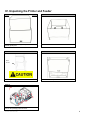
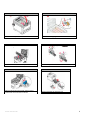
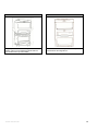
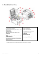
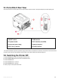
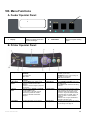
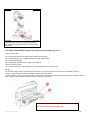
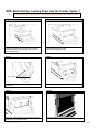
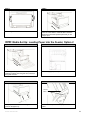
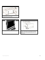
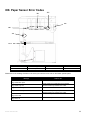
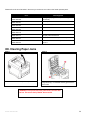
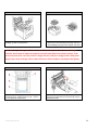
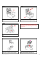
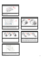
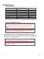
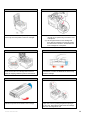
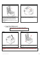
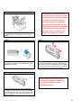
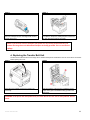
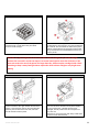
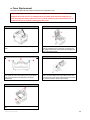
iTerra Elite ll User Guide December 2010: Revision 001 1 Table of Contents I. II. III. IV. V. VI. VII. VIII. IX. X. XI. XII. XIII. XIV. XV. XVI. XVII. XVIII. XIX. XX. XXI. XXII. Limitation of Liability iTerra Elite ll Warranty Safety Information a. 120 Volt Models b. 220/240 Volt Models Unpacking the Printer and Feeder iTerra Elite Front View iTerra Elite Rear View Switching the Printer Off Menu Functions a. Feeder Operator Panel b. Printer Operator Panel How to Change the Settings: User How to Change the Settings: Administrator Printer Configuration Menu Print Information Menu Printer Shutdown Menu Major Printer Components and Paper Path Feeder Part Names Loading Cut Sheet Paper into the Paper Tray Media Set Up: Loading Paper into the Feeder, Option 1 Media Set Up: Loading Paper into the Feeder, Option 2 Paper Sensor Error Codes Clearing Paper Jams Maintenance a. Order Information b. Toner Cartridge Replacement c. Image Drum Replacement d. Replacing the Transfer Belt Unit e. Fuser Replacement iTerra Elite II Printer Specifications December 2010: Revision 001 3 4 5 6 7 6 11 12 12 13 13 13 14 14 15 16 16 17 18 18 20 21 23 24 28 28 28 30 32 34 35 2 I. Limitation of Liability The Imaging Systems Group’s total liability to the purchaser, or to any third party, for damages from any and all causes whatsoever, regardless of the form of action, whether in contract or in tort, including negligence, and any infringement of proprietary rights or any misappropriation or unlawful use of any proprietary rights or property of any third party shall, in the aggregate, be limited to purchase price actually paid by the purchaser for the product relating to the damages. The limitation of liability provisions of this agreement reflect an informed voluntary allocation of the risks (known and unknown) that may exist in connection with the provisions of the goods and services provided hereunder by The Imaging Systems Group Inc. and that such voluntary risk allocation represents a fundamental part of the agreement reached between The Imaging Systems Group Inc. with the purchaser. The Imaging Systems Group Inc. shall not be liable for any special, direct or indirect, incidental, consequential, exemplary, punitive or any similar or other damages of any nature suffered by the purchaser whatsoever including, without limitation, loss of use or lack of availability of the purchaser facilities, including its computer resources and any stored data, loss of profits or revenue, or other commercial loss, or any claim for contribution or indemnity in respect of any claims against the purchaser, regardless of whether The Imaging Systems Group Inc. has been advised of the possibility of such damages. The Imaging Systems Group Inc. 911 28 Street NE Calgary, Alberta, Canada T2A 7X1 www.isys-group.com www.isys-media.com Phone: 1-403-204-5200 Fax: 1-403-204-1971 Toll Free: 1-866-415-4797 e-mail: [email protected] December 2010: Revision 001 3 II. iTerra Elite ll Warranty iSys - The Imaging Systems Group Inc. (iSys) warrants the iTerra Elite ll (Product) to be free from defects in materials and workmanship and will remedy any such defect according to the terms of this Limited Warranty. iSys warrants the Product to be free from defects in material and workmanship occurring under normal usage, within the normal operating range and duty cycles specified. If the iSys Customer Service Representative Department receives notice of such defects during the warranty period, iSys at its option, and within a reasonable time, will repair or replace the defective Product. A certified iSys service representative shall perform repairs, and such repairs, at the option of iSys, may be performed at the customer site, a dealer site, a service depot or the factory. Replacement Product, at the option of iSys, may be either new or equivalent in performance to new. Delivery is defined by a signed and dated receipt from the original carrier or iSys dealer delivering the Product, or down time for repair and replacement. iSys does not warrant the operation of the Product to be uninterrupted or error free. iSys assumes no liability for and holds itself harmless against any claims of consequential costs or damages which may arise from interruption or error in the operation of the Product. iSys does not warrant defects, malfunctions and/or failures, which in its opinion, result from conditions of improper use, abuse, neglect, operation outside the published environmental specifications, improper site preparation and maintenance, the use of unqualified or unauthorized media (papers, films, toners, inks, fusers or belts), inadequate preventative maintenance, unauthorized modifications or unauthorized maintenance. Such conditions shall render this warranty void and otherwise release iSys from its liability under this Product warranty. Consumables are non-warranty items. All product returned to factory must be accompanied by an RMA number, obtained by calling the iSys Service Department at 403-2045200 or as otherwise instructed. Shipping and handling charges to vendor for repair are the sole responsibility of the customer. iSys will cover shipping charges on the return of the repaired unit for the term of the warranty as stated above. Shipping will consist of Standard Shipment level or Best Effort. Accelerated or Premium Shipping Service is available but costs will be fully born by customer. Any international duties and taxes payable on transporting the repaired unit across international borders will be the responsibility of the customer. The Elite ll Printer is a Canadian made product and therefore falls under the import/export laws of NAFTA. A written receipt for the Product, showing the date of purchase, dealer’s name, and both the model and serial number/PID’s of the Product must accompany any request or claim for work to be performed under this Limited Warranty. Additional information on obtaining service under this Limited Warranty or for obtaining Extended Warranty coverage contact iSys – The Imaging Systems Group directly at 866-415-iSys (4797) or at 403-204-5200. iSys or its authorized service partner will repair, or at its option replace, at no charge, any defective component(s) of the Product for a period of one (1) year from the date of purchase. This Limited Warranty extends to the original purchaser only. This Limited Warranty does not extend to consumable items. TO THE EXTENT ALLOWED BY LOCAL LAW, THIS WARRANTY IS EXCLUSIVE AND NO OTHER WARRANTY OR CONDITION, WHETHER WRITTEN OR ORAL, IS EXPRESSED OR IMPLIED AND THE IMAGING SYSTEMS GROUP INC. SPECIFICALLY DISCLAIMS ANY IMPLIED WARRANTIES INCLUDING, BUT NOT LIMITED TO, WARRANTIES OF MERCHANTABILITY, FITNESS FOR A PARTICULAR PURPOSE AND QUALITY SATISFACTION. THE WARRANTY TERMS CONTAINED HEREIN, EXCEPT TO THE EXTENT LAWFULLY PREMITTED, DO NOT EXCLUDE, RESTRICT OR MODIFY AND ARE IN ADDITION TO APPLICABLE STATUTORY RIGHTS. USE OF THE PRODUCT CONSTITUTES ACCEPTANCE OF THIS WARRANTY. December 2010: Revision 001 Corporate Headquarters: iSys –group 911-28th Street NE Calgary AB T2A 7X1 Canada www.isys-group.com 1-866-415-iSys (4797) 4 III. Safety Information 120 Volt Models Your iSys product has been carefully designed to give you years of safe, reliable performance. As with all electrical equipment, there are a few basic precautions you should take to avoid hurting yourself or damaging the product. Save all provided documentation for future reference. Read and follow all warning and instruction labels on the product itself. Unplug the product before you clean it. Use only a damp cloth; do not use liquid or aerosol cleaners. Place your product on a firm, solid surface. If placed on something unsteady, it may fall and be damaged. If placed on a soft surface, the vents may be blocked, causing the product to overheat. Protect your product from overheating. Make sure no obstructions block the openings of the product. Do not put the product on or near a heat source (such as a radiator or heat register). Keep the product out of direct sunlight. Always use this product in a well ventilated area. Allow enough room around the product for adequate ventilation and easy access to the paper trays. If the product is placed in any kind of enclosure, make sure the enclosure is well ventilated. Do not use the product near water. Do not spill liquid of any kind on it. Be certain that your power source matches the rating listed on the back of the product. If you are not sure, check with your dealer or local power company. Do not connect this product to an uninterruptible power supply (UPS). Your product has a grounded, three-prong plug as a safety feature. This plug only fits into a grounded outlet. If the plug does not fit, the outlet may be an older, non-grounded type. Contact an electrician to have the outlet replaced. Do not use an adapter to defeat the grounding. Install the product near an easily accessible power outlet. Avoid damaging the power cord. Do not put anything on it or place it where it will be walked on. If the cord becomes damaged or frayed, replace it immediately. If you are using an extension cord or power bar with the product, make sure the total amperes required by all the equipment on the extension is less than the extension’s rating. The total ratings of all equipment plugged into the outlet should not exceed 15 amperes. Do not poke anything in the ventilation slots of the product. You could get an electrical shock or cause hazardous electrical arcing, which could cause a fire. Aside from the routine maintenance described in the documentation, do not try to service the product yourself. Removing the cover may expose you to shocks or other hazards. Do not make any adjustments other than those outlined in the documentation. You may cause damage that will require extensive repair work. The provided documentation explains how to get your product serviced by qualified iSys technicians. If anything happens that indicating your product is not working properly or has been damaged, unplug it immediately and follow the procedures in the provided documentation for having your product serviced. Here are some of the things to look for. The power cord or plug is frayed or damaged. Liquid has been spilled into the product, or the product has been exposed to water. The product has been dropped, or the cabinet is damaged. The product does not function normally when following the operating instructions. December 2010: Revision 001 5 December 2010: Revision 001 6 December 2010: Revision 001 7 IV. Unpacking the Printer and Feeder STEP 1 STEP 2 With two people lift the top (feeder) box off of the bottom (printer) box. Open the feeder box. Remove the feeder. STEP 3 STEP 4 Back of cart Position the feeder at the back of the cart as shown. Lift the lid off of the printer box. STEP 5 With two people, remove the printer from the box and remove the packaging tape as shown. December 2010: Revision 001 8 STEP 6 STEP 7 Press button to open lid. Remove fuser shipping lock. STEP 8 STEP 9 Pull the drums/toners out of the printer. Remove the protective film. STEP 10 STEP 11 Place the drums and toners back into the printer. Lock all four toners into the four drums. Remove the letter tray shipping lock. December 2010: Revision 001 9 STEP 12 STEP 13 Keep the printer level while lowering it onto the feeder; ensure you are aligning the printer with the pins located on the top of the feeder. When the iTerra Elite II is fully assembled the printer should look like the image above. December 2010: Revision 001 10 V. iTerra Elite II Front View 1. Output stacker, face down 5. Paper level indicator Standard printed copy delivery point. Holds up to 350 sheets at 80g/m². 2. Operator panel 6. Front cover release lever Menu driven operator controls and LCD* panel. 3. Paper tray Standard paper tray. Holds up to 530 sheets of 80g/m² paper. 4. Multi purpose tray Used for feeding heavier paper stocks, envelopes and other special media. Also for manual feeding of single sheets when required. 7. Multi-purpose tray release recess 8. Top cover release button 9. LED heads 10. Fuser release levers 11. Toner cartridges (C,M,Y,K) 12. ID units (C,M,Y,K) 13. Duplex unit (when fitted) *The display language can be changed to show English, French, Spanish or Portuguese. December 2010: Revision 001 11 VI. iTerra Elite II Rear View This view shows the connection panel, the rear output stacker and the location of the optional duplex (two-sided printing) unit. 1. ON/OFF switch 5. USB interface 2. AC power socket 6. ACC interface (host USB) 3. Duplex unit (when fitted) 7. Network interface* 4. Rear, face up stacker 8. Parallel interface * The Network Interface may have a protective “plug” which must be removed before connection can be made. This view shows the connection panel, the rear output stacker and the location of the optional duplex (two-sided printing) unit. VII. Switching the Printer Off 1. Press the Enter button on the control panel to enter the menu. 2. Press the Menu down button and scroll to the Shutdown menu. 3. Press the Enter button. 4. Press the Enter button to continue. 5. Press the Enter button to execute. 6. At the prompt, turn the power switch OFF. December 2010: Revision 001 12 VIII. Menu Functions A. Feeder Operator Panel: 2 1 1. Display Displays the feeder status and any error messages 2. Load Button Press to complete loading paper B. Printer Operator Panel: 1.Ready LED ON: Ready to receive data BLINKING: Processing data. OFF: Offline 6. Attention LED 2. Display Displays the printer Status and any error messages. Enters the Menu mode. IN Menu mode, forwards or reverses the menu item displayed. Press for 2 seconds or longer to jump from top to bottom Switches between ONLINE and OFFLINE Scrolls the HELP screen Forced printing on the paper currently loaded when pressed with “WONG PAPER” or “WRONG PAPER SIZE” displayed. 7. Back Button Provides advice when an error such as incorrect paper size occurs 10.Power Save/ Wake up Button 3. Menu Scroll Buttons 4. On Line Button 5. Help Button December 2010: Revision 001 ON: A warning occurs. Printing may be possible (e.g low toner) BLINKING: An error occurs. Printing not possible (e.g toner empty) OFF: Normal Condition Returns to the previous higher level menu 8. Enter Button In the ONLINE or OFFLINE mode: enters the Menu mode. In the Menu mode: determines the setting selected. 9. Cancel Button Deletes the data being printed or received when pressed for two seconds or longer. Deletes the data when pressed for two seconds or longer with WRONG PAPER SIZE, RUN OUT OF PAPER, TRAY 1 IS OPEN, or TRAY 1 IS NOT FOUND is displayed. Exits the menu and goes ONLINE when pressed in the Menu mode. Pressing this button switches the machine into sleep or wake- up mode. Refer to “Power saving mode” page 12. 13 IX. How to Change the Settings: User It should be noted that many of these settings can be, and often are, overridden by settings in the Windows printer drivers. However, several of the driver settings can be left at “Printer Setting”, which will then default to the settings entered in these printer menus. Where applicable, factory default settings are shown in bold type in the following tables. In the normal operating condition, known as “standby,” the printer’s LCD window will show “Ready to Print”. In this condition, to enter the menu system, press the up and down Menu buttons on the operator panel to move up and down through the list of menus until the menu you wish to view is displayed. Then proceed as follows: 1. Press Enter to enter the menu. 2. Use the up and down MENU buttons on the control panel to scroll through the menus. When the item you want to change is displayed, press Enter to view the sub-menus for that item. 3. Use the up and down MENU buttons to move up and down through the sub-menu items. When the item you want to change is displayed press Enter to display the setting. 4. Use the up and down MENU buttons to move up and down through the available settings for the sub-menu item. When the item you want to change is displayed press Enter to display the setting. An asterisk (*) will appear next to the setting, indicating that this setting is currently in effect. 5. Do one of the following: •Press Back again to move up to the list of menus; or… • Press On Line or Cancel to exit from the menu system and return to standby. X. How to Change the Settings: Administrator You can set whether to ENABLE or DISABLE each category in the user menu. Disabled categories are not displayed in the User’s menu. Only a system administrator can change these settings. 1. Turn OFF the printer. Turn ON the printer while pressing the Enter button. When Boot Menu appears, take your finger off the button. 2. Press the Enter button. 3. At the Enter Password prompt, enter the 4-9 digit Admin password: (a) Using the up and down MENU buttons, scroll to the required letter/digit. (b) Press the Enter button to input and move to the next letter/digit. (c) Repeat steps (a) and (b) until all letters/digits are entered. Enter your 4 to 9 digit password. (The default password is aaaaaa). 4. Press the Enter button. 5. Press the up or down MENU button until the “category” you want to change is displayed. 6. Press the Enter button. 7. Press the up or down MENU button until the “item” you want to change is displayed. 8. Press the Enter button. 9. Using the up or down MENU button, identify the parameter as required. 10. Press the Enter button to enter an asterisk (*) on the right side of the setting selected. 11. Press the On Line button to switch to online. The machine will automatically re-boot. December 2010: Revision 001 14 XI. Printer Configuration Menu ITEM ACTION EXPLANATION Tray Count Tray1 Select an item to display the total number of pages printed from the relevant tray. Supplies Life Cyan Drum Magenta Drum Yellow Drum Black Drum Belt Fuser Select item to display the percentage of a consumable remaining. Network Printer Name Short Printer Name IPv4 Address Displays the full printer name. Displays an abbreviated version. Displays the IPv4 Address of the network. Displays the Gateway Address of the network. Displays the Mac Address of the printer. Displays the Network firmware revision. Displays the Web remote version. Displays the IPv6 Address (Local) of the network. Displays the IPv6 Address (Global) of the network. Gateway Address MAC Address Network FW version Web Remote version IPv6 Address (Local) IPv6 Address (Global) Remote version System a. Serial Number Asset Number Lot Number CU Version PU Version Total Memory Flash Memory SD Card Date and Time Displays information for these items. Display condition: IP Version v4+v6 or IP v6 December 2010: Revision 001 15 XII. Print Information Menu This menu provides a quick method of listing various items stored within the printer. ITEM ACTION EXPLANATION Configuration Execute Select execute to print out a configuration report. Network Execute Scroll down to this parameter and select execute to print out Network information. Demo Page DEMO1 Execute Scroll down to this parameter and select execute to print out a demonstration page. File List Execute PS font List Execute Scroll down to this parameter and select execute to print out a list of job files. (displayed only if FileSystem is installed). Scroll down to this parameter and select execute to print out a Postscript emulation typeface list. PCL font List Execute Scroll down to this parameter and select execute to print out a PCL font list. IBM PPR Font List Execute Scroll down to this parameter and select execute to print out an IBM PPR font list. EPSON FX Font List Execute Scroll down to this parameter and select execute to print out an Epson FX emulation font list. Usage Report Execute Scroll down to this parameter and select execute to print out a list of color and mono pages printed. Error Log Execute Scroll down to this parameter and select execute to print out the error log. Color Profile List Execute Scroll down to this parameter and select execute to print out a list of color profiles. XIII. Printer Shutdown Menu This item should always be selected before switching the printer off, to ensure that no data is lost. ITEM ACTION EXPLANATION Shutdown Start December 2010: Revision 001 Execute Performs controlled shutdown of the printer. Only power the printer off when the display Indicates that shutdown is complete. 16 XIV. Major Printer Components and Paper Path 2 3 4 1 5 6 7 8 9 1. 2. 3. 4. 5. 6. 7. 8. 9. December 2010: Revision 001 Paper Exit Fuser Unit Top Cover Printer Operator Panel Front Cover Cut Sheet Paper Tray Feeder Operator Panel Fan Fold Paper Tray Feeder 17 XV. Feeder Part Names: XVI. Loading Cut Sheet Paper into the Printer Tray STEP 1 STEP 2 Remove the paper tray from the printer. Fan the paper to be loaded at the edges (1) and in the middle (2) to ensure that all sheets are properly separated, and then tap the edges of the stack on a flat surface to make it flush again (3). December 2010: Revision 001 18 STEP 3 Load paper (letter headed paper face down and top edge towards the front of the printer), as shown. Adjust the rear stopper (a) and paper guides (b) to the size of paper being used. iTerra Elite II: IMPORTANT: Set paper size dial to the size of paper being used. To prevent paper jams: •Do not leave space between the paper and the guides and rear stopper. •Do not overfill the paper tray. Capacity depends on the type of paper stock. •Do not load damaged paper. •Do not load paper of different sizes or types at the same time. •Close the paper tray gently. •Do not pull the paper tray out during printing (except as described below for the 2nd tray). NOTES: For face down printing, make sure the face up (rear) stacker (a) is closed (the paper exits from the top of the printer). Stacking capacity is approximately 350 sheets for the Elite II, depending on paper weight. For face up printing, make sure the face up (rear) stacker (a) is open and the paper support (b) is extended. Paper is stacked in reverse order. Capacity is approximately 100 sheets of 20-lb. US Bond (75 g/m2) paper. CAUTION: Do not open or close the rear paper exit while printing as it may result in a paper jam. December 2010: Revision 001 19 XVII: Media Set Up: Loading Paper into the Feeder, Option 1 NOTE: Please ensure the rear face up stacker is open before printing fanfold paper. (See section VI, page 12) STEP 1 STEP 2 Push the guide tray latches inward and pull the guide tray forward. Open the guide door, load door and guide channels. Place paper in the paper tray with TOF mark facing upward and aligned to the right. STEP 3 STEP 4 Tension Roller Lift tension roller up and slide the paper between both rollers. Pull paper towards the front. STEP 5 STEP 6 Center the paper between the guide channels until it is lightly touching the feed rollers. Close the guide channels and the load door. December 2010: Revision 001 20 STEP 7 STEP 8 Close the guide door. Slide in the guide tray; ensure the tray is fully latched. Press the “Load” button, “STATUS: IDLE” should be displayed on the feeder operator panel and you are ready to print. XVIII: Media Set Up: Loading Paper into the Feeder, Option 2 STEP 1 STEP 2 Push the guide tray latches inward and pull the guide tray forward. Open the guide door, load door and guide channels. Front loading paper path is pictured above. STEP 3 STEP 4 Tension Roller Insert paper in the front bottom loading slot until it goes into the paper tray. December 2010: Revision 001 Lift tension roller up and slide the paper between both rollers. 21 STEP 5 Center the paper between the guide channels until it is lightly touching the feed rollers. STEP 6 STEP 7 Close the guide channels and the load door. Slide in the guide tray; ensure the tray is fully latched. Press the “Load” button, “STATUS: IDLE” should be displayed on the feeder operator panel and you are ready to print. December 2010: Revision 001 22 XIX. Paper Sensor Error Codes 381 385 382 380 392 10-11 Code # 380 381 382 Location Paper Feed Upper Paper Transport Paper Exit Code # 385 392 10 - 11 Location Fuser Paper Feed Lower Load Sensors Please refer to the message list below in the event you receive an error code on the feeder operator panel. Message Msg: Guide Door Open Msg: Guide Tray Out Msg: Close Door/Tray Msg: Close Door/Tray Guide Tray Door Msg: Funnel Full Msg: Path Full What To Do Ensure Guide Door is Closed Push Guide Tray Completely into the Feeder. Ensure Guide Tray Latches are Locked. Ensure Guide Door is Closed Push Guide Tray Completely into the Feeder. Ensure Guide Tray Latches are Locked. Remove all Paper from the Guide. Remove allPaper PaperRemains from the Guide. Ensure No in the Guide Funnel. Ensure Paper Remains in the Guide Funnel. Reload No Fanfold Paper Manually. Reload Fanfold Paper Manually. December 2010: Revision 001 23 Please refer to the error list below in the event you receive an error code on the feeder operator panel. Error Status: Error 00 What Happened Emergency stop (guide door opened during motor movement) Switch panel communication error Status: Error 01 Internal error Status: Error 02 Internal error Status: Error 03 Media not found over lower load sensor after load Status: Error 10 Status: Error 11 Media not positioned between load sensors properly after load advance Cutter did not leave home position in required time Status: Error 31 Status: Error 32 Cutter did not finish cut in required time or can't home it XX. Clearing Paper Jams STEP 1 STEP 2 Press the cover release and open the top cover. Note the position of the four toners cartridges (a) and image drums (b). It is essential that they go back in the same order. WARNING: If the printer has been powered on, the fuser will be hot. This area is clearly labeled. Do not touch. December 2010: Revision 001 24 STEP 3 STEP 4 Lift the image drum, complete with its toner cartridge, up and out of the printer Put the assembly down gently onto a piece of paper to prevent toner from staining surrounding areas and to avoid damaging the green drum surface and cover. CAUTION: The green image drum surface at the base of the Image Drum is very delicate and light sensitive. Do not touch it and do not expose it to normal room light for more than 5 minutes. If the drum unit needs to be out of the printer for longer than this, wrap the cartridge inside a black plastic bag to keep it away from light. Never expose the drum to direct sunlight or very bright room lighting. STEP 5 STEP 6 Check if any sheets of paper are visible on any part of the belt unit (a. release handle, b. belt, c. fuser or d. fuser pressure release lever). To remove sheet from the front, lift the sheet from the belt and pull it forward into the internal drum cavity to withdraw the sheet. December 2010: Revision 001 25 STEP 7 STEP 8 To remove a sheet from the central area, separate the sheet from the belt surface and withdraw the sheet. To remove a sheet in the fuser; push the two retaining levers (e) towards the rear of the printer t0 release the fuser. Withdraw the fuser unit using the handle (f). STEP 9 NOTE: If the sheet is well advanced into the fuser (only a short length is still visible), do not attempt to pull it back. Press release lever (g) and pull trapped paper from the fuser. STEP 10 STEP 11 Replace fuser unit into the machine and move locking levers (e) toward the rear of the machine. Starting with the cyan image drum unit nearest the fuser, replace the four image drums into the drum cavity, making sure to locate them in the correct order. December 2010: Revision 001 26 STEP 12 Open the rear exit tray (h) and check for sheets of paper in the rear path area (i), pull out any sheets found in this area. STEP 13 STEP 14 If the sheet is low down in this area and difficult to remove, it is probably still gripped by the fuser. In this case raise the top cover, reach around and press down on the fuser pressure release lever (d). Pull down the MP tray using the depressions. Lift the front cover release lever and lower the front cover. STEP 15 STEP 16 Check inside the cover for sheets in this area and remove any that you find, and then close the cover. Pull out the paper tray and ensure all paper is stacked properly, is undamaged, and that the paper guides are properly positioned against the edge of the paper stack. When satisfied replace the tray. Close the top cover and press down firmly so the cover latch closes. STEP 17 Pull out the paper guide tray, clear out any paper jams. Reload fan fold paper and close the paper guide tray. December 2010: Revision 001 27 XXI. Maintenance a. Order Information Only use iSys products to ensure the best quality and performance from your hardware. Using other products may adversely affect your printer's performance and invalidate your warranty. Item Life ELITE II ORDER NO. Toner, black Toner, Cyan Toner, Yellow Toner, Magenta Image drum, black Image drum, cyan Image drum, Magenta Image drum, yellow Transfer Belt Fuser (120V) Fuser (230V) *Based on continuous print. 11,000 Letter @ 5% 11,500 Letter @ 5% 11,500 Letter @ 5 % 11,500 Letter @ 5% 30,000 Letter pages * 30,000 Letter pages * 30,000 Letter pages * 30,000 Letter pages * 60,000 Letter pages * 60,000 Letter pages * 60,000 Letter pages * 600-1360 600-1362 600-1366 600-1364 600-1370 600-1372 600-1374 600-1376 600-1380 600-1381 600-1382 b. Toner Cartridge Replacement NOTE: When the LCD display indicates TONER LOW, or if print appears faded, first open the top cover and try tapping the cartridge a few times to evenly distribute the toner powder. This will enable you to obtain the best “yield” from your toner cartridge. CAUTION! To avoid toner wastage and possible toner sensor errors, do not change the toner cartridge(s) until “TONER EMPTY” is displayed. Have a sheet of paper handy so that you have somewhere to place the used cartridge while you install the new one. Dispose of the old cartridge responsibly, inside the pack that the new one came in. Follow any regulations, recommendations, etc., which may be in force concerning waste recycling. If you do spill any toner powder, lightly brush it off. If this is not enough, use a cool, damp cloth to remove any residue. Do not use hot water, and never use solvents of any kind. They will make stains permanent. WARNING! If you inhale any toner or get it in your eyes, drink a little water or bathe your eyes liberally in cold water. Seek medical attention immediately. WARNING! If the printer has been powered on, the fuser may be hot. This area is clearly labeled. Do not touch. December 2010: Revision 001 28 STEP 1 Press the cover release and open the printer’s top cover fully. Note the position of the four cartridges. STEP 2 (a) Pull the colored toner release lever on the cartridge to be replaced fully towards the front of the printer. (b) Lift the right hand end of the cartridge and then draw the cartridge to the right to release the left hand end as shown, and withdraw the toner cartridge out of the printer. STEP 3 STEP 4 Clean the top of the ID unit with a clean, lint free cloth. Remove the new cartridge from its box but leave its wrapping material in place for the moment. Gently shake the new cartridge from end to end several times to loosen and distribute the toner evenly inside the cartridge. STEP 5 STEP 6 Remove the wrapping material and peel off the adhesive tape from the underside of the cartridge. Insert the left end of the cartridge into the top of the image drum unit first; pushing it against the spring on the drum unit, then lower the right end of the cartridge down onto the image drum unit. December 2010: Revision 001 29 STEP 7 STEP 8 Pressing gently down on the cartridge to ensure that it is firmly seated, push the colored lever towards the rear of the printer. This will lock the cartridge into place and release toner into the image drum unit. Gently wipe the LED head surface with a clean, lint free cloth. Finally close the top cover and press down firmly at both sides so that the cover latches closed. c. Image Drum Replacement The printer contains four image drums: cyan, magenta, yellow and black. CAUTION! Static sensitive devices, handle with care. STEP 1 STEP 2 Press the cover release and open the printer’s top cover fully. Note the position of the four toner cartridges (a) and image drums (b) it is essential that they go back in the same order. WARNING! If the printer has been powered on, the fuser will be hot. This area is clearly labeled. Do not touch. December 2010: Revision 001 30 STEP 3 Holding it by its top centre, lift the image drum, complete with its toner cartridge, up and out of the printer. CAUTION! The green image drum surface at the base of the ID unit is very delicate and light sensitive. Do not touch it and do not expose it to normal room light for more than 5 minutes. If the drum unit needs to be out of the printer for longer than this, please wrap the cartridge inside a black plastic bag to keep it away from light. Never expose the drum to direct sunlight or very bright room lighting. STEP 4 STEP 5 With the colored toner release lever (1) to the right, pull the lever towards you. This will release the toner cartridge from the drum. Lift the right hand end of the toner cartridge (1) and then draw the cartridge to the right to release the lefthand end as shown (2) and withdraw the toner cartridge out of the image drum cartridge. Place the cartridge on a piece of paper to avoid marking your furniture. STEP 6 NOTE: Follow the instructions that come with the new image drum for additional information such as the removal of packaging material etc. Place the toner cartridge onto the new image drum cartridge as shown. Push the left end in first and then lower the right end in. (It is not necessary to fit a new toner cartridge at this time unless the remaining toner level is very low.) December 2010: Revision 001 31 STEP 7 STEP 8 Push the colored release lever away from you to lock the toner cartridge onto the new image drum unit and release toner into it. Holding the complete assembly by its top center, lower it into place in the printer, locating the pins at each end into their slots in the sides of the printer. NOTE: If you need to return or transport your printer for any reason, please make sure you remove the image drum unit beforehand and place in the bag provided. This is to avoid toner spillage. d. Replacing the Transfer Belt Unit The belt unit is located under the four image drums. Switch off the printer and allow the fuser to cool for about 10 minutes before opening the cover. STEP 1 STEP 2 Press the cover release and open the printer’s top cover fully. Note the positions of the four toner cartridges (a) and image drums (b) it is essential that they go back in the same order. WARNING! If the printer has been powered on, the fuser will be hot. This area is clearly labeled. Do not touch. December 2010: Revision 001 32 STEP 3 STEP 4 Lift each of the image drum units out of the printer and place them in a safe place away from direct sources of heat and light. Locate the two fasteners (a) at each side of the belt and the lifting bar (b) at the front end. Turn the two fasteners 90˚ to the left. This will release the belt from the printer chassis. Pull the lifting bar (b) upwards so that the belt tilts up towards the front, and withdraw the belt unit (c) from the printer. CAUTION! The green image drum surface at the base of each cartridge is very delicate and light sensitive. Do not touch it and do not expose it to normal room light for more than 5 minutes. If the drum unit needs to be out of the printer for longer than this, please wrap the cartridge inside a black plastic bag to keep it away from light. Never expose the drum to direct sunlight or very bright room lighting. STEP 5 STEP 6 Lower the new belt unit into place, with the lifting bar at the front and the drive gear towards the rear of the printer. Locate the drive gear into the gear inside the printer by the rear left corner of the unit, and lower the belt unit flat inside the printer. Turn the two fasteners (a) 90˚ to the right until they lock. This will secure the belt unit into place. Replace the four image drums, complete with their toner cartridges, into the printer in the same sequence as they came out. Close the top cover and press down firmly at both sides so that the cover latches closed. December 2010: Revision 001 33 e. Fuser Replacement The fuser is located inside the printer just behind the four image drum units. WARNING! If the printer has recently been powered on, some fuser components will be very hot. Handle the fuser with extreme care, holding it only by its handle, which will only be mildly warm to touch. A warning label clearly indicates the area. If in doubt, switch the printer off and wait at least 10 minutes for the fuser to cool before opening the printer cover. STEP 1 STEP 2 Press the cover release and open the printer’s top cover fully. Identify the fuser handle (a). Pull the two fuser retaining levers (b) towards the front of the printer so that they are fully upright. Remove the new fuser from its packaging and remove the transit material STEP 3 STEP 4 Holding the new fuser by its handle, make sure that it is the correct way round. The retaining levers (b) should be fully upright, and the two locating lugs (c) should be towards you. Lower the fuser into the printer, locating the two lugs in the slots in the metal partition which separates the fuser from the image drums .Push the two retaining levers (b) towards the rear of the printer to lock the fuser in place. STEP 5 Place the drums back into the printer and replace the lid. December 2010: Revision 001 34 XXII. iTerra Elite II For MSDS Sheets please visit: http://www.isys-media.com/view_category.asp?cat=92 December 2010: Revision 001 35