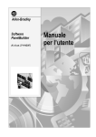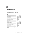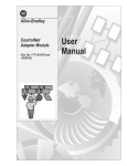
1
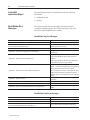
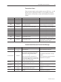
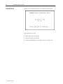
User Guide
Introduction
This document describes how to connect and configure
communications for the ControlNet versions of the PanelView
terminals. This document provides supplemental information for
the PanelBuilder Software User Manual (Publication 2711-6.0) and
PanelView Operator Terminals User Manual (Publication 2711-6.1).
For information about:
Go to page:
Related Publications
2
Before You Use this Guide
2
ControlNet Protocol
3
Compatible ControlNet Controllers
3
ControlNet PanelView Terminals
3
Typical ControlNet Network
4
Making ControlNet Connections
5
NAP Connector Pinout Definitions
5
NAP and Redundant Cables
5
Modifying ControlNet Settings from the Terminal
6
Displaying ControlNet Internal Tag Data
8
Setting Up Communications using PanelBuilder
Selecting a ControlNet Terminal
9
Configuring ControlNet Communications
10
Supported Data and Address Types
11
Tag Addressing
11
File Conversions
12
Downloading Applications
12
ControlNet Application Report
14
PanelBuilder Error Messages
14
Channel Status Field
15
Error Messages and Codes
16
Terminal Alert Codes
17
Terminal Communication Status and Alert Messages
17
Internal Errors
18
Glossary
19
Publication 2711-6.10
2
ControlNet Communications
Related Publications
The following documentation provides additional information about
installing, configuring and using your PanelView terminals:
Publication Title
Publication No.
PanelBuilder Software User Manual
2711-6.0
PanelView Operator Terminals User Manual
2711-6.1
PanelBuilder Software Getting Started
2711-6.2
For more information on ControlNet related products, refer to:
Publication Title
ControlNet System Overview
ControlNet Cable System Planning and Installation Manual
ControlNet Cable System Component List
Publication No.
1786-2.9
1786-6.2.1
AG-2.2
Note: The Allen-Bradley website (www.ab.com) provides
information and product descriptions of ControlNet products. Under
the Products and Services heading, select Communications.
Before You
Use this Guide
You should be familiar with ControlNet communications.
If you want to learn more about ControlNet, refer to the related
publications list above.
Note: Refer to the glossary at the back of this document for
definitions of terms you are not familiar with.
Publication 2711-6.10
ControlNet Communications
ControlNet Protocol
3
The PanelView terminal supports release 1.5 of ControlNet.
Unscheduled (peer) addressing of tags is supported. Scheduled (I/O)
addressing is not supported.
ControlNet allows a flexible control architecture that can work with
multiple processors and up to 99 nodes (via taps) anywhere along the
trunk cable of the network. There is no minimum tap separation and
you can access the ControlNet network from every node (including
adapters).
Compatible ControlNet
Controllers
The ControlNet PanelView supports unscheduled PCCC
(Programmable Controller Communication Command) messaging
with the following controllers:
• PLC-5/20C
• PLC-5/40C
• PLC-5/60C
• PLC-5/80C
ControlNet PanelView
Terminals
ControlNet terminals have a 15 on the end of the catalog number, for
example 2711-T9A15.
The ControlNet terminals have:
• ControlNet communication port
• RS-232 printer/file transfer port
In addition, each terminal is available with either AC or DC power
input. The characters L1 at the end of the catalog number designate
a terminal with DC power input (e.g. 2711-T9A15L1).
Publication 2711-6.10
4
ControlNet Communications
Typical ControlNet
Network
Shown below is a typical ControlNet network with a PanelView 900
installed on a network drop.
PanelView 900
2711-T9A15 Shown
RS-232 Port
ControlNet Port
BNC Coaxial Cable
Printer
Computer for developing
PanelView applications
or
Serial Link
1784-KTC(X) Card to
ControlNet (RSLinx) & Win PFT
Personal
Computer
Personal
Computer
1784-KTC(X)
Interface Card
PLC-5/20C
Serial Link
1770-KFC
1786-RG6 Cable
PLC-5/40C
Flex I/O
(1794-ACN)
Repeater
(1786-RPT)
PLC-5/80C
= Taps
= Terminators
Important: Do not connect to a network using both the redundant
cable BNC connector and the Network Access Port (NAP).
Publication 2711-6.10
ControlNet Communications
Making ControlNet
Connections
5
Refer to the following pinout information to connect the PanelView
to a ControlNet network.
Important: Follow the ControlNet network layout and design as
specified in the ControlNet Cable System Planning and Installation
Manual (Publication 1786-6.2.1).
PanelView 900 Shown
Redundant BNC Cable Connectors
NAP Connector
Channel B
Channel A
NAP Connector Pinout
Definitions
NAP and Redundant
Cables
Pin 1
Pin #
NAP Signal
1
Signal Common
2
No Connection
3
TX_H
4
TX_L
5
RX_L
6
RX_H
7
No Connection
8
Signal Common
Shell
Earth Ground
ControlNet cables, taps, connectors, terminators and repeaters are
available. Refer to the ControlNet Cable System Planning and
Installation manual (Publication 1786-6.2.1) for descriptions of
these components. For information on purchasing these items, refer
to the Allen-Bradley ControlNet Cable System Component List
(Publication AG-2.2).
Item
RG-6 quad-shield cable
Coax repeater
Coax taps
Catalog No.
1786-RG6
1786-RPT, -RPTD
1786-TPR, -TPS, -TPYR, -TPYS
Network access cable
1786-CP
Coax toolkit
1786-CTK
Segment terminators
BNC connectors
1786-XT
1786-BNC, -BNCJ, -BNCP, -BNCJ1
Publication 2711-6.10
6
ControlNet Communications
Modifying ControlNet
Settings from the Terminal
The PanelView terminal displays ControlNet settings and allows
changes to the the Node Address and Interscan Delay. From the
Configuration Mode menu of the terminal, select Communication
Setup. The screen below appears.
!
ATTENTION: Settings downloaded with a
ControlNet application have priority over terminal
settings. ControlNet settings take effect immediately
after an application is downloaded.
PV600 Screen Shown
Other Types Similar
New Node Address [F2]
Select the New Node Address field to open the numeric entry
scratchpad. Enter the node addresss of the PanelView terminal
(01 to 99) and press the enter key (on touch screen terminals, press
the enter key on the scratchpad). A change to the node address takes
effect after the terminal is reset. Note: If you enter a value greater
than the UMAX node address, the PanelView will not go online with
the network.
Active Node Address
Read only field displays the current address of the PanelView
terminal.
Interscan Delay [F3]
Displays the current Interscan delay in milliseconds. Select the
Interscan Delay field to open the numeric entry scratchpad. Enter
the delay (100 to 1000 milliseconds in multiples of 10) and press the
enter key (on touch screen terminals, press the enter key on the
scratchpad). A change takes effect immediately.
FW Revision
Displays the currently loaded ControlNet firmware revision.
Publication 2711-6.10
ControlNet Communications
7
Serial Number
Read only field that displays the 32 bit serial number of the
PanelView. The serial number is unique for each ControlNet device.
Channel Status
Read only field that displays the current status of redundant channels
A and B as a value. Refer to page 15 for definitions of each
displayed value.
Comms Status
Message display containing the current status of the communication
card. “Connected” is displayed when the PanelView is connected to
the network and properly operating. Pages 16 & 17 list the terminal
messages related to ControlNet communications.
Restart Terminal [F1]
Performs a re-boot of the terminal. A new node address takes effect
after a reset.
Exit [F10] or [F16]
Returns to the main Configuration Mode menu.
Publication 2711-6.10
8
ControlNet Communications
Viewing Other ControlNet
Parameters
The following ControlNet related fields may be placed on an
application screen using internal tags. These read only fields are
maintained by the network keeper and do not appear unless added to
a screen. Refer to Displaying ControlNet Internal Tag Data (next
section).
Network Update Time (NUT)
Displays the network update time in milliseconds.
UMAX Node
Displays the ControlNet network’s Unscheduled Maximum node
address (UMAX) setting. The UMAX node is the highest
ControlNet address that can communicate during the unscheduled
portion of the network update interval. The PanelView node address
must be set to a value less than or equal to the UMAX setting to
enter on to the network.
SMAX Node
Displays the ControlNet network’s Scheduled Maximum Node
address (SMAX) setting. The SMAX node is the highest ControlNet
node address that can communicate during the scheduled portion of
the network update interval. The PanelView does not currently
support scheduled messaging.
Displaying ControlNet
Internal Tag Data
The Network Update Time, UMAX Node, SMAX Node, and other
data may be displayed on an application screen by assigning a
display object to one of the following internal data tags.
Data
Internal Tag
Network Update Time (NUT).
@Read_DCNUTtime
unsigned integer
Unscheduled Maximum (UMAX)
node address.
@Read_DCUMAX
unsigned integer
Scheduled Maximum (SMAX) node
address.
@Read_DCSMAX
unsigned integer
Current node address.
@Read_curDCAddress
unsigned integer
CIP/ASA serial number of the
PanelView.
@Read_DCASANumber
string *
Communication status number.
@Read_DCCommStatus
unsigned integer
ControlNet firmware revision
number.
@Read_DCFirmwareRev
string *
Terminal address to use after a
reset.
@Read_DCNewAddress
unsigned integer
Firmware build date.
@Read_DCProtocol
LED status number. Indicates
status of A & B cables.
@Read_DCRedundancy
unsigned integer
Scan delay in milliseconds (time
between reads).
@Read_DCScanDelay
unsigned integer
* You must use an ASCII display for tags with a string data type.
Publication 2711-6.10
Data Type
string *
ControlNet Communications
Setting up
Communications
using PanelBuilder
9
Creating a ControlNet application includes:
1. Selecting a ControlNet terminal when creating the application.
2. Configuring ControlNet communication parameters for the
terminal.
Selecting a ControlNet PanelView Terminal
Select a ControlNet terminal for a PanelView application from:
• New Application dialog when creating a new application
• Terminal Setup dialog when converting an application created for
another terminal.
Any catalog number ending with 15 (2711-xx15) is a ControlNet
terminal.
Catalog numbers with 15 at the end
indicates a terminal with a ControlNet port.
Publication 2711-6.10
10
ControlNet Communications
Configuring ControlNet Communications
ControlNet communication parameters are accessed from the
Terminal Setup dialog. To open the Terminal Setup dialog, choose
Terminal Setup from the PanelBuilder Application menu.
1. Click the Comms. Setup button from the Terminal Setup dialog.
2. Under Terminal, edit the following parameters:
Specify:
To:
Node Address
Select the address 01 to 99 (decimal, default is 3)
of the PanelView terminal. Each node on the
network must be assigned a unique address.
Interscan Delay
Select an interscan delay of 100 to 1000
milliseconds (default is 100 ms).
3. Under Network Nodes (click on right mouse button to access or
insert), edit the following parameters for controller nodes on the
ControlNet network connected to the PanelView:
Specify:
To:
Node Name
Enter a unique name for the node (controller) on
the ControlNet network connected to the
PanelView. The name can be up to 32 characters
long.
Node Address
Enter the node address of the device (01 to 99).
Node Type
Select pull-down list selects the controller type:
Allen-Bradley PLC
4. Click OK to return to the Terminal Setup dialog. Click OK to
save changes and exit Terminal Setup. Important: Any changes
are not saved until OK is selected on the Terminal Setup dialog.
Publication 2711-6.10
ControlNet Communications
11
Tag Addressing
Use the PanelBuilder tag editor to assign tag addresses. ControlNet
tag addresses use the same format as the Allen-Bradley DH+
protocol. Refer to your controller’s programming manual for tag
addressing formats.
Supported Data
and Address Types
The following Allen-Bradley PLC-5 File/Data type operations are
supported.
Note: Reads from and Writes to I/O are not supported.
Data Types
Binary
(B)
Integer
(N)
Bit Read
✔
Bit Write
Integer Read
32 Bit
IEEE
Float
(F)
ASCII
(A)
BCD
(D)
Status
(S)
Control
(R)
Timer
(T)
Counter
(C)
✔
✔
✔
✔
✔
✔
✔
✔
✔
✔
✔
✔
✔
✔
✔
✔
✔
✔
✔
✔
✔
✔
✔
Integer Write
✔
✔
✔
✔
✔
✔
✔
✔
Float Read
✔
✔
✔
✔
✔
✔
Float Write
✔
✔
✔
✔
✔
✔
BCD Read
✔
✔
✔
✔
✔
✔
✔
✔
BCD Write
✔
✔
✔
✔
✔
✔
✔
✔
Bit Array
Read
✔
✔
✔
✔
✔
✔
✔
✔
Bit Array
Write
✔
✔
✔
✔
✔
✔
✔
✔
Unsigned
Integer Read
✔
✔
✔
✔
✔
✔
✔
✔
Unsigned
Integer Write
✔
✔
✔
✔
✔
✔
✔
✔
Character
Array Read
✔
✔
✔
✔
✔
✔
Character
Array Write
✔
✔
✔
✔
✔
✔
Operations
Allowed
String
(ST.)
Publication 2711-6.10
12
ControlNet Communications
File Conversions
PanelBuilder provides automatic conversions between DH+ and
ControlNet applications. To convert applications between DH+ and
ControlNet protocols:
1. Open the application.
2. Select Terminal Setup from the Application menu.
3. Select the version of the terminal that supports the protocol to
which you want to convert the application. Terminal catalog
numbers with a 15 on the end are ControlNet terminals and
terminal catalog numbers with an 8 on the end are DH+.
4. When you select OK, the file is converted to the new protocol.
Note: Default communication parameters are used:
Node = 3
Scan Delay = 100 msec
Download / Upload
Applications
Downloading / Uploading Applications through the Serial
(RS-232) Port
To download or upload a ControlNet application from your computer
to the PanelView terminal over an RS-232 link (DF1 protocol), refer
to the instructions provided in the PanelBuilder Software user
manual.
Downloading / Uploading Applications through the ControlNet
Port
To download/upload a ControlNet application from your computer to
the PanelView terminal through the ControlNet port:
• connect computer with 1784-KTC(X) card to ControlNet port
• download or upload application from the PanelBuilder
Application menu
• refer to the instructions on the next page for downloads.
Uploading application configurations is similar.
Publication 2711-6.10
ControlNet Communications
13
To download applications through the PanelView ControlNet
port:
➀ Open the application you want to download.
➁ Choose Download from the Application menu.
➂ Select the Download parameters.
Click OK when done
Select Operator Terminal
Setup button is
active if more than
one terminal is
available.
Select RSLinx
Shows ControlNet
driver is active
Enter name of .PVA file in which to
save the translated .PBA file
➃ Application is validated and translated to a .PVA file.
If errors or warnings are detected, the Exceptions dialog opens.
You must correct errors before download can proceed.
➄ PanelBuilder Software and terminal display status of download.
’TEST.PVA’
➅ Terminal verifies, resets, and starts application.
Note: If a download is aborted (by the user or by a communications
error), no application is saved and ControlNet communication
settings are set to defaults (Node =3, Interscan Delay = 100 msec).
Publication 2711-6.10
14
ControlNet Communications
ControlNet
Application Report
The application printout for ControlNet provides the following
information:
• configuration data
• tag data
PanelBuilder Error
Messages
The following table lists error messages and codes specific to
ControlNet communications. For all other messages, refer to the
PanelView and PanelBuilder user manuals.
PanelBuilder Tag Error Messages
Message
Recommended Action / Notes
<Tag Name> – Not a ControlNet address tag.
Correct and save the tag in the Tag Form Dialog.
<Tag Name> – Array size (<Value>) is invalid.
You must enter a value between 1 and N.
N will have a value of 128 or 84 depending on the
address type used for the array.
<Tag Name> – Node Name address matches the terminal node address.
Correct value in the Tag Form Dialog.
<Tag Name> – Tag node not configured as a ControlNet node.
Configure the network node in the Communications
Setup Dialog
Tags referencing different data types cannot be grouped.
Tags referencing different network nodes cannot be
grouped.
<Tag Name> – Data may not be consistent with tag.
Tags referencing different data files cannot be grouped.
Tag separation too large for group definition.
Multiple write tags cannot be grouped. In ”Alarm
Setup...”, correct the alarm trigger tag and corresponding
alarm callout tags to remove the error condition.
<Tag Name> – Data may not be consistent with tag <Tag Name>
The 2nd <Tag Name> in each error message is the alarm
trigger tag which determines the properties of the tag
group to which the corresponding alarm callout tags must
adhere.
The tag must be removed from all uses in the
application.
<Tag Name> – Illegal I/O reference.
<Tag Name> – Illegal timer/counter read operation.
<Tag Name> – Illegal write to timer status bits.
<Tag Name> - References beyond maximum data file size of 999 elements.
The use of the tag must be changed in the application
editor.
PanelBuilder Node Error Messages
Message
<Device Name> – Not configured as a ControlNet node.
Recommended Action / Notes
Configure the node in the Communications Setup Dialog.
<Device Name> – No InterScan delay assigned, default to 100 ms.
<Device Name> – InterScan delay (<Value> ms) is invalid.
You must enter a value between 100 ms and 1000 ms.
Publication 2711-6.10
Correct value in the Communications Setup Dialog.
ControlNet Communications
15
PanelBuilder Translation Error Messages
Message
Recommended Action / Notes
Translation Failure
Contact Allen-Bradley for technical support.
Too many internal resources required by application.
Close any other applications that may be using memory.
Too many communication resources required by application.
Tag addresses should be grouped together as much as
possible, otherwise screen objects must be removed.
<Tag Name> – Exceeds maximum reference size of N element(s).
Decrease number of states where tag is an LSB trigger.
<Tag Name> – References beyond maximum file size of 999 elements.
Change tag address to reference a lower data address.
Channel Status Field
Displayed
Value
119
118
117
116
115
114
113
112
103
102
101
100
99
98
97
96
The Channel Status field on the terminal communications screen (see
page 6) displays a value that indicates the current status of both
channel A and channel B. You can also display the status on a
screen using an internal tag (@Read_DCRedundancy), see page 8.
Use the following table to convert the value to a channel A and
Channel B status condition. The definitions of each status condition
follows the table.
Status
A
B
7
7
6
7
5
7
4
7
3
7
2
7
1
7
0
7
7
6
6
6
5
6
4
6
3
6
2
6
1
6
0
6
Displayed
Value
87
86
85
84
83
82
81
80
71
70
69
68
67
66
65
64
Status
A
B
7
5
6
5
5
5
4
5
3
5
2
5
1
5
0
5
7
4
6
4
5
4
4
4
3
4
2
4
1
4
0
4
Displayed
Value
55
54
53
52
51
50
49
48
39
38
37
36
35
34
33
32
Status
A
B
7
3
6
3
5
3
4
3
3
3
2
3
1
3
0
3
7
2
6
2
5
2
4
2
3
2
2
2
1
2
0
2
Displayed
Value
23
22
21
20
19
18
17
16
7
6
5
4
3
2
1
0
Status
A
B
7
1
6
1
5
1
4
1
3
1
2
1
1
1
0
1
7
0
6
0
5
0
4
0
3
0
2
0
1
0
0
0
Channel A & B Status Codes
Code
Indicates:
Priority ➀
7
Terminal failure. Contact Allen-Bradley for technical support.
1 (Highest)
6
Self test being performed. Wait for end of test.
2
5
Incorrect node configuration. Check for duplicate nodes.
3
4
Incorrect network configuration (overflow/underflow if signaled by host, out-of-step, etc.).
Check for a node greater than UMAX.
4
3
Cable fault or lonely connection (disconnected cable, redundancy warning, etc.).
5
2
Temporary network errors (bad MAC frame, screeners not programmed, modem not online, etc.).
6
1
Channel ok.
0
Channel disabled.
7
8 (Lowest)
➀ If multiple status conditions apply, the highest priority condition is displayed.
Publication 2711-6.10
16
ControlNet Communications
Error Messages
and Codes
The following tables lists error messages and codes specific to
ControlNet communications. For all other messages, refer to the
PanelView and PanelBuilder user manuals.
Communication Status Error Codes
These errors appear at the top of an application screen or on the
terminal configuration screen. If you should get an alert number that
is not listed here, contact Allen-Bradley for technical support.
Alert Number
Alert Type
Indicates:
Recommended Action(s):
The PanelView was detected as having a
duplicate node address and is in the
listen–only mode. Check the node address
(MAC ID) of the devices on the network to
verify that addresses are not duplicated.
1803
Informational
The communications device has completed the
request to force the device into the listen-only
state.
1824
Warning
The PanelView was forced to a listen only state.
Contact Allen-Bradley for technical support.
1826
Warning
A fixed tag packet was received but there is no
place to route the packet. The data packet is
discarded and the error message is displayed.
Contact Allen-Bradley for technical support.
1828
Warning
An attempt was made to open an unsupported
transport class.
Contact Allen-Bradley for technical support.
1829
Warning
An attempt to open a Class 1 transport with
application triggering or a Class 3 transport with
cyclic triggering.
Contact Allen-Bradley for technical support.
3333
Warning
A connection has timed out.
A file transfer was unexpectedly interrupted.
Publication 2711-6.10
ControlNet Communications
17
Terminal Alert Codes
These messages appear on the terminal screen as DC Error = xx and
alert the user to a particular condition. If you should get an alert
number that is not listed here, contact Allen-Bradley for technical
support.
Alert Number
Alert Type
Indicates:
Recommended Action(s):
9000
Critical fault
Interface startup failed.
Contact Allen-Bradley for technical support.
9003
Critical fault
CIP S/N is not valid.
Contact Allen-Bradley for technical support.
9004
Critical fault
Out of buffers
Contact Allen-Bradley for technical support.
9010
Critical fault
Invalid target node, target node is the same as the
PV, or larger than UMAX.
Check node addresses of all devices on the
network including the PanelView terminal.
9012
Communications
Warning
ControlNet object received a reset request.
Contact Allen-Bradley for technical support.
9014
Critical fault
A fatal CPU fault occurred.
Contact Allen-Bradley for technical support.
9015
Critical fault
A ControlNet hardware fault occurred.
Contact Allen-Bradley for technical support.
9016
Critical fault
RAM verification failed at startup.
Contact Allen-Bradley for technical support.
9017
Critical fault
CRC verification failed at startup.
Contact Allen-Bradley for technical support.
9018
Critical fault
A critical internal error occurred.
Contact Allen-Bradley for technical support.
9019
Critical fault
An internal fault occurred.
Reset terminal, if problem occurs again,
contact Allen-Bradley for technical support.
9020
Critical fault
An internal fault occurred.
Reset terminal. If problem occurs again,
reload application. If problem persists, contact
Allen-Bradley for technical support.
Communication Status and Terminal Alert Messages
Message
Alert Type
PanelView off–line.
Communications
warning
Initial write failed.*
Reminder
Indicates:
Recommended Action(s):
PanelView off–line.
Check communication connections.
Write to Logic Controller on Startup was configured
and on powerup, the PanelView could not write
initial values to a node’s data table address.
or
Write to Logic Controller on Startup was not
configured and the PanelView was unable to write
a logic controller. Note: The error message is only
displayed on the first write attempt.
Check/define data table address in the logic
controller.
Check communication connections and node
configuration in the application.
Write fail.*
Communications
warning
PanelView is communicating with logic controller.
The data table address does not exist.
Check/define data table address in the logic
controller.
Write timeout.*
Communications
warning
PanelView is not communicating with the logic
controller.
Check communication connections and node
configuration in the application.
Read fail.*
Communications
warning
PanelView is communicating with logic controller.
The data table address does not exist.
Check/define data table address in the logic
controller.
Read timeout.*
Communications
warning
PanelView is not communicating with the logic
controller.
Check communication connections and node
configuration in the application.
* These messages display the node number associated with the message.
Publication 2711-6.10
18
ControlNet Communications
Internal Errors
Internal errors are displayed in an error banner as shown below:
If an internal error occurs:
1. Write down the error message.
2. Reset the PanelView terminal.
3. Contact Allen-Bradley for assistance if error is still present.
Publication 2711-6.10
ControlNet Communications
Glossary
19
Adapter
ControlNet device which responds to scanner messages (sometimes
called a slave device).
Bridge
Device that allows network data to pass from one link to another
link.
DF1
Allen-Bradley communication protocol based on an ANSI
X3.28-1976 specification.
DF1/FD
Full duplex variation of DF1 which allows a two-way simultaneous
transmission with embedded responses.
DH+
Data Highway Plus. An Allen-Bradley token-passing baseband link
for a local area network.
Interscan Delay
Determines the amount of time the PanelView terminal waits before
re-reading current screen data from the logic controller.
Keeper
The network controller of a ControlNet network.
Link
A collection of nodes with unique addresses in the range of 01 to 99
(decimal).
Network
Collection of connected nodes including the connection paths,
repeaters and bridges.
Network Access Point (NAP)
Port that provides temporary access to a ControlNet network through
an RJ-45 connector.
Node
Any device connected to the ControlNet cable system which requires
a network address to function.
NUT
Acronym for Network Update Time. The ControlNet network
update time established for the communications link.
PCCC
Acronym for Programmable Controller Communication Commands.
Publication 2711-6.10
20
ControlNet Communications
PLC
Acronym for Programmable Logic Controller identified by the 1785Catalog number prefix.
Repeater
Two-port component that receives and transmits all data from one
segment to another segment.
RIO
Acronym for Remote Input Output. An Allen-Bradley proprietary
master-slave communication protocol.
Scheduled Messages
Messages that occur at a regular specified interval. Scheduled
messages are assigned a particular portion of the network update
time (NUT) and are always transmitted at that time.
Segment
Trunk-cable sections connected through taps with terminators at each
end and no repeaters.
SMAX
Highest ControlNet node address which can communicate during the
scheduled portion of the network update interval.
Tap
Hardware component that connects devices to the ControlNet trunk
cable.
Trunk Cable
Bus or central part of a cable system.
UMAX
Highest ControlNet node address which can communicate during the
unscheduled portion of the network update interval.
Unscheduled Messages
Messages that are sent on an as needed basis. Unscheduled messages
are sent during the unscheduled portion of the Network update
interval.
Publication 2711-6.10
Rockwell Automation helps its customers receive a superior return on their investment by bringing
together leading brands in industrial automation, creating a broad spectrum of easy-to-integrate
products. These are supported by local technical resources available worldwide, a global network
of system solutions providers, and the advanced technology resources of Rockwell.
Worldwide representation.
Argentina • Australia • Austria • Bahrain • Belgium • Bolivia • Brazil • Bulgaria • Canada • Chile • China, People’s Republic of • Colombia • Costa Rica • Croatia • Cyprus
Czech Republic • Denmark • Dominican Republic • Ecuador • Egypt • El Salvador • Finland • France • Germany • Ghana • Greece • Guatemala • Honduras • Hong Kong
Hungary • Iceland • India • Indonesia • Iran • Ireland • Israel • Italy • Jamaica • Japan • Jordan • Korea • Kuwait • Lebanon • Macau • Malaysia • Malta • Mexico • Morocco
The Netherlands • New Zealand • Nigeria • Norway • Oman • Pakistan • Panama • Peru • Philippines • Poland • Portugal • Puerto Rico • Qatar • Romania • Russia • Saudi
Arabia • Singapore • Slovakia • Slovenia • South Africa, Republic of • Spain • Sweden • Switzerland • Taiwan • Thailand • Trinidad • Tunisia • Turkey • United Arab Emirates
United Kingdom • United States • Uruguay • Venezuela
Rockwell Automation Headquarters, 1201 South Second Street, Milwaukee, WI 53204-2496 USA, Tel: (1) 414 382-2000 Fax: (1) 414 382-4444
Rockwell Automation European Headquarters, Avenue Hermann Debroux, 46, 1160 Brussels, Belgium, Tel: (32) 2 663 06 00, Fax: (32) 2 663 06 40
Rockwell Automation Asia Pacific Headquarters, 27/F Citicorp Centre, 18 Whitfield Road, Causeway Bay, Hong Kong, Tel: (852) 2887 4788, Fax: (852) 2508 1846
World Wide Web: http://www.ab.com
Publication 2711-6.10 – April 1998
40061-387-01(A)
CopyrightPublication
1998 Allen-Bradley
Company,– Inc.
2711-6.10
AprilPrinted
1998in USA