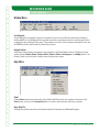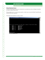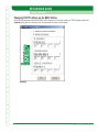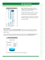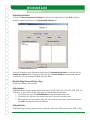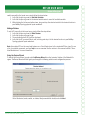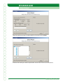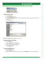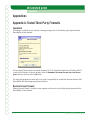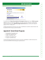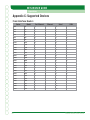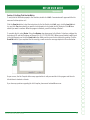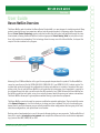
1
NETSIM USER GUIDE
Overview
User Guide
Boson NetSim Overview
The Boson NetSim, which includes the Boson Router Simulator®, is a new category of simulation product. Many
products simulate the end-user experience without actually emulating what is happening within the network.
Boson’s Virtual Packet Technology creates individual packets that are routed and switched through the simulated network, allowing the Boson NetSim to build an appropriate Virtual Routing Table for each protocol and,
thus, fully emulate true networking. This technology allows for many uses of the Boson NetSim, far beyond the
scope of the labs included in the program.
!CHIEVING#ISCO##.!CERTIlCATIONISTHEGOALOFMANYPEOPLEWHOPURCHASETHISPRODUCT4HE"OSON.ET3IM
covers far more than just the full CCNA (640-801), ICND (640-811), and INTRO (641-821) subject matter. The
INCLUDEDLABSGUIDEYOUTHROUGHTHECONlGURATIONOFROUTERSANDSWITCHESINAVARIETYOFSCENARIOS!FTERCOMpleting a lab, you can ask the Boson NetSim to self-grade the lab to determine if you completed it correctly. As
you progress through the labs, you will master the skills needed to be a CCNA. Because the Boson NetSim has
the ability to guide and self-grade, using it can actually be more helpful than using real routers and switches.
The Boson NetSim allows you to gain experience without having to purchase the equipment.
4HE"OSON.ET3IMCANALSOBEUSEDFORMANYNONCERTIlCATIONORIENTEDAPPLICATIONS4HEINCLUDEDFULLVERSION
of the Network Designer is a tool that allows you to design and plan a network. This tool’s functionality goes
BEYONDTHATOFMOSTTOOLSBECAUSEYOUCANACTUALLYCREATETHEROUTERCONlGURATIONSTHATAREGOINGTOBEUSED
SAVETHOSECONlGURATIONSANDUPLOADTHEMTOREALROUTERS
Routing protocol implementation is one of the more challenging tasks you may encounter. The Boson NetSim allows you to create a virtual pilot or test network and compare the differences in the results before implementing a protocol like IGRP, EIGRP, RIP, or OSPF.
Boson NetSim User Guide
1
NETSIM USER GUIDE
Overview
Troubleshooting a production network can be a frightening and frustrating experience. Fortunately, you can
create a virtual copy of your network with the Boson Network Designer and troubleshoot the problems without
interfering with your production network.
)NSUMMARYTHE"OSON.ET3IMISAmEXIBLEANDPOWERFULPRODUCTTHATCANHELPYOUBECOMECERTIlEDANDCANAID
you in the design and troubleshooting of complex networks.
!N/VERVIEWOF5SINGTHE"OSON.ET3IM4O0REPAREFOR9OUR#ERTIlCATION
4HE#ISCOCERTIlCATIONSREQUIREYOUTOLEARNANDMASTERANUMBEROFSKILLS4HISDISCUSSIONWILLTELLYOUHOWTO
INCORPORATETHE"OSON.ET3IMASPARTOFTHELEARNINGPROCESSANDHOWYOUCANSUCCESSFULLYCOMPLETEYOURCERTIlcation track by using the Boson NetSim.
Basically, mastering Cisco networking involves two fundamental tasks: learning the theory of routers and switchESANDGAININGTHEHANDSONEXPERIENCEOFIMPLEMENTINGTHATTHEORYBYCONlGURINGTHEDEVICESINANETWORKAND
testing them in a lab. The theory can be learned by reading books or listening to an instructor. The purpose of the
Boson NetSim is to help you with the practical hands-on portion of your education and to ensure that you not only
UNDERSTANDTHECONCEPTSOFROUTINGBUTCANACTUALLYCONlGUREANDIMPLEMENTROUTINGON#ISCODEVICES
Once you feel you have mastered both the theory and the practical labs, you can test your knowledge using the
Boson ExSim practice exam products available at http://www.boson.com. Boson ExSim products include complex
multiple-choice questions, drag-and-drop questions, and other types of simulation questions when appropriate.
4HE"OSON.ET3IMISTHEMOSTCOMPREHENSIVEPRODUCTONTHEMARKETFORLEARNINGHOWTOCONlGUREA#ISCOROUTER
4HE"OSON.ET3IMWILLNOTONLYHELPYOUBECOMECERTIlEDBUTITWILLACTUALLYHELPYOULEARNANDUNDERSTANDHOW
TOCONlGUREROUTERSSWITCHESANDNETWORKS
2
Boson NetSim User Guide
NETSIM USER GUIDE
Basic Lab Tutorial
Basic Lab Tutorial
Basic Simulator Features
!FTERINSTALLING"OSON.ET3IMYOUCANCHOOSEONEOFTWOWAYSTOSTARTTHEPROGRAM4HElRSTWAYISTODOUBLE
click the Boson NetSim icon placed on your desktop during installation. The second way to start the Boson
NetSim is through the Windows Start menu.
You must agree to be bound by the terms and conditions of the Single User License Agreement (SULA) to register,
activate, or otherwise use any portion of the software.
Overview
4HISTUTORIALWILLGUIDEYOUTHROUGHTHElRSTLABUSINGTHEBASICFEATURESOFTHE"OSON.ET3IM)TWILLSHOWYOU
HOWTOSELECTALABCONlGURETHEDEVICESANDTHENGRADETHELAB4HElRSTLABTHATYOUWILLCOMPLETEISVERY
simple, but following it will give you an understanding of the components of the Boson NetSim and how they
interoperate. Advanced features and more functionality will be covered later.
Simulator Components
The Simulator is actually a suite of programs that interact to provide a total learning experience. The primary
components are as follows:
1. Lab Navigator
2. Network Designer (optional)
3. Network Simulator
4. Lab Grader
The purpose of the Lab Navigator is to allow you to view, select, and begin the lab of your choice. The Lab Navigator provides a friendly interface for your learning experience.
The included Network Designer is a tool you can use to create your own custom networks. With this tool, you
can build either a simple or complex network; you can even model an existing network. Note that the Network
Designer is not required to complete the included labs. The Network Designer is provided solely to allow you to
practice creating and administering your own Cisco networks.
The Network Simulator is the tool that actually simulates the network and routes virtual packets. This program
ALLOWSYOUTOCONTROLNUMEROUSDEVICESANDCONlGURETHEMASNEEDED4HE.ETWORK3IMULATORISNOTLIMITEDTO
performing only the tasks in the lab; it can do much, much more.
4HE,AB'RADERANALYZESTHECONlGURATIONYOUHAVECOMPLETEDANDDETERMINESWHETHERYOUHAVECOMPLETEDTHE
lab correctly.
Boson NetSim User Guide
3
NETSIM USER GUIDE
Basic Lab Tutorial
eLearning Lab Flow
The three basic components involved in completing a lab are as follows:
1.
Use the Lab Navigator to load the lab.
5SETHE.ETWORK3IMULATORTOCONlGURETHEDEVICESROUTERSSWITCHESANDSTATIONS
5SETHE,AB'RADERTOOLTOCHECKYOURLABANSWERSCONlGS
All three components described above will now be covered in detail.
Part 1: The Lab Navigator
7HENYOUOPENTHEPROGRAMYOUWILLENCOUNTERTHElRSTSCREENBELOW%ACHTABACROSSTHELEFTSIDEOFTHEAPplication represents a series of labs. Clicking on one of those tabs will reveal the lab topics in the middle window.
This is the initial Lab Navigator screen.
To get started with a lab, click the Stand-Alone Labs tab, and then select Lab 1: Connecting to a Router.
4
Boson NetSim User Guide
NETSIM USER GUIDE
Basic Lab Tutorial
Select the Stand-Alone Labs tab in the Lab Navigator.
Double-click the name of the lab. You should see the following introductory screen, which provides a brief overview of the lab and gives you the options of viewing the lab instructions, loading the lab, or canceling.
Starting a lab
Boson NetSim User Guide
5
NETSIM USER GUIDE
Basic Lab Tutorial
View Lab
Clicking the View LabBUTTONWILLOPENAN!DOBE!CROBATlLECONTAININGTHEINSTRUCTIONSFORTHELABTHATYOU
selected. You can choose to print the lab at this time or follow along in the PDF.
Load Lab
When you click the Load Lab button, you will be asked if you would like to load the corresponding topology into
the Simulator. Answering Yes will display the Simulator in the background and create new windows, each of
which represents a new device (e.g., a router, a switch, or a PC).
Part 2: The Network Simulator
Once the lab is loaded, you will see the following screen:
After this device prompt screen is displayed, you are ready to begin the lab.
Complete the lab as follows:
1. If you have not done so already, click the eRouters button located at the top of your screen, and select
Router 1. The Router 1 interface will open, and the text “Press Enter to Start” will appear as shown in
the following exhibit.
6
Boson NetSim User Guide
NETSIM USER GUIDE
Basic Lab Tutorial
2. Click inside the Router 1 interface window, and press the ENTER key on your keyboard to get started.
When you press the ENTER key, you connect to Router 1 and receive the Router> prompt. The prompt
consists of two parts: the host name and the mode. Router is Router 1’s original host name, and the >
symbol indicates user EXEC mode.
3. Next, type the enable command to get to the privileged EXEC mode prompt (Router#). Your input appears in bold below:
Router>enable
Router#
Boson NetSim User Guide
7
NETSIM USER GUIDE
Basic Lab Tutorial
4. Finally, to return to user mode, simply type disable. From user mode, type logout or exit to leave the
router. Your input appears in bold below:
Router#disable
Router>
Router>exit
Router con0 is now available
Press RETURN to get started
You have now completed all the steps in this introductory lab. To grade your lab, select the Grade Lab button on
the top toolbar of the Lab Navigator.
Part 3: The Lab Grader
4HE,AB'RADERISANEASYTOUSETOOLFORDETERMININGWHETHERYOUHAVECOMPLETEDTHETASKSASDElNEDINTHE
LAB4HISISAUSEFULTOOLTOENSUREYOUAREMASTERINGTHESKILLSREQUIREDFORYOURCERTIlCATION
The three basic steps to use the Lab Grader:
1. Select the lab you have completed.
2. Tell the program to grade your lab.
3. Review the results.
Select the Lab
To select the lab you are working on, click the down arrow to the right of the drop-down box, and select the appropriate lab.
8
Boson NetSim User Guide
NETSIM USER GUIDE
Basic Lab Tutorial
Grade the Lab
After you have selected the lab, click the Grade Me button. The program will then begin an analysis of your curRENTROUTERANDSWITCHCONlGURATIONSANDCOMPARETHEMTOTHEEXPECTEDCONlGURATIONOFTHEDEVICES
Review Your Results
If you receive the same result as shown below, you have completed all necessary commands to accomplish the
lab’s objectives, and you are now ready to move on to the next lab. If not, you need to return to the lab, correct the
errors, and grade the lab again.
The Lab Grader results
At this point, you have completed the Basic Lab Tutorial and are ready to move on to the Advanced Lab Tutorial in
the next section.
Boson NetSim User Guide
9
NETSIM USER GUIDE
Advanced Lab Tutorial
Advanced Lab Tutorial
This tutorial will demonstrate the Boson NetSim’s Advanced mode. These advanced features are optional, and you
DONOTHAVETOUSETHEADVANCED3IMULATORFEATURESTOPROPERLYCOMPLETETHELABSORPREPAREFORYOURCERTIlCATION(OWEVERTHE!DVANCEDMODEWILLTEACHYOUVALUABLESKILLSTHATWILLAIDYOUINTHElELDANDINTHEREALWORLD
Otherwise, you can complete this lab using the basic functionality of the Simulator as described in the previous
section.
Step 1: Launch the Simulator
To get started, launch the Boson NetSim.
Step 2: Set Advanced Mode (Telnet)
From within the Boson NetSim, select the Advanced Mode (Telnet) option under the Modes menu.
After the Control Panel (horizontal toolbar) appears, simply click the NetMap button to review the currently loaded
default network topology.
This will launch the NetMap Viewer application as a separate process, so you can use the ALT+TAB key combination to switch between your network diagram and the other Boson NetSim components. The default NetMap is
shown below:
10
Boson NetSim User Guide
NETSIM USER GUIDE
Advanced Lab Tutorial
The NetMap Viewer showing your current network diagram
#OLORLEGENDASDElNEDINTHE"OSON.ETWORK$ESIGNER
1.
2.
3.
4.
Blue is Ethernet
Red is ISDN/Dialup or PRI
Black is Serial PPP
White is Serial Frame
Boson NetSim User Guide
11
NETSIM USER GUIDE
Advanced Lab Tutorial
Step 3: Lab Navigator Utility
To start a lab or lesson, click the Lab Navigator button on the top horizontal toolbar (as shown below), or select
it from the Window menu. This launches the Cisco CCNA Lab Navigator application as a separate process, so
you can use the ALT+TAB key combination to move between the labs and multiple Telnet windows.
The easy way to load the Lab Navigator utility
Within the Lab Navigator, you can access the included labs by selecting one of the tabs shown on the left and
choosing a lab from the list that appears.
Tips:
The labs are organized into sections to match the
Lab Navigator content bar, as shown to the left.
For the purpose of this lab walkthrough, please select the Stand-Alone Labs tab, which will show all of the labs
in that category.
Next, select Lab 2 - Introduction to the Basic User Interface. This lab will be used for this tutorial.
12
Boson NetSim User Guide
NETSIM USER GUIDE
Advanced Lab Tutorial
Lab 2 from the Stand-Alone Labs
Step 4: Different Methods for Telnet in Advanced Mode
There are a total of four methods for launching your default Telnet program and automatically connecting to the
SELECTEDDEVICE0ICKONETOCONTINUEWITHTHETUTORIALORTRYEXPERIMENTINGWITHALLFOURMETHODS4HElRSTSTEP
of this lesson’s lab is simply to use Telnet to connect to Router 1.
Telnet Method 1 of 4: Directly from within the NetMap Viewer, right-click Router 3 (or any device), and select
#ONlGURE. (Note that if you double-click the device instead of right-clicking, a Device Statistics window will
appear instead of a Telnet window.)
The moment you select #ONlGURE, your default Telnet application will connect to the selected Router 3.
Boson NetSim User Guide
13
NETSIM USER GUIDE
Advanced Lab Tutorial
Telnet Method 2 of 4: Left-click the Routers button on the Control Panel (top horizontal toolbar) to receive a list
OFDEVICESCURRENTLYCONlGUREDWITHINTHEEXISTING.ET-AP4OPOLOGY
The moment you select 2OUTER, your default Telnet application will connect to the selected Router 3.
Telnet Method 3 of 4: Click the Devices Control Panel menu, expand eRouters by holding the mouse pointer over
it, and select Router 3.
The moment you select 2OUTER, your default Telnet application will connect to the selected Router 3.
Telnet Method 4 of 4: If you have closed the Remote Control vertical toolbar, please re-launch the toolbar by
clicking the Remote Control button within the Control Panel horizontal toolbar:
From the Remote Control vertical toolbar, click the Telnet to eRouter button to receive a list of routers currently
CONlGUREDWITHINTHEEXISTING.ET-AP4OPOLOGY3ELECTRouter 3 from the pop-up menu. The moment you select
Router 3, your default Telnet application will connect to Router 3.
14
Boson NetSim User Guide
NETSIM USER GUIDE
Advanced Lab Tutorial
Boson Remote Control
3TEP#ONlGURING2OUTERWITH4ELNET
Assuming you are using the default telnet.exe program provided by the Windows operating system, you should
see a Telnet window with the default Cisco router prompt of Router> for Router 3. With what you have just
learned, select Router 1.
Carry out the instructions in Lab 2. When you have completed step 8, which is the last step in this particular
lab, you should be shown how to log off the router. When you type exit, you will effectively log off the router;
however, Telnet will still be open.
Telnet window attached to Router 1 showing the result at the end of Lab 2
$ONOTCLOSETELNETEXEYET'RADEYOURLABWITHTHE"OSON.ET3IM,AB'RADERTOOLlRST
Boson NetSim User Guide
15
NETSIM USER GUIDE
Advanced Lab Tutorial
Step 6: Self-Grade Your Lab
From within the Lab Navigator, select the Grade Lab button at the top of the screen. Once you left-click the Grade
Lab button, the self-grading utility will launch and will default to the last lab that you loaded from the dropdown list. See the following exhibit.
Selecting Lab 2 to grade
)TISIMPORTANTTONOTETHATTHESELFGRADEUTILITYMUSTBEEXPECTINGTHEINCLUDEDLABCONlGURATIONINORDERTO
function properly. This means that if you are following labs that are not included within the Boson NetSim labs,
THENTHISFEATUREMUSTlRSTBECONlGUREDTOEXPECTTHECORRECTLABINPUT
From within the Grade My Lab screen, use the drop-down list to select Lab 2, and then click the Grade Me butTON)FANYDEVICECONlGURATIONHASANERRORYOUWILLBENOTIlEDINTHEBOXBELOWTHEGrade Me button.
You may now close your Telnet program; to do so in the normal Windows fashion, click the X button (the standard
close-window button) in the upper-right corner of the window.
16
Boson NetSim User Guide
NETSIM USER GUIDE
Feature Overview
Feature Overview
Control Panel (Main Menus)
The main menus are located on the top of the Control Panel (horizontal toolbar) page and are accessed one of
TWOWAYS4HElRSTWAYISTOMOVETHEMOUSECURSOROVERTHEAPPROPRIATEMENUANDCLICKTHEMENUTODISPLAYTHE
MENUOPTIONS7HENYOUlNDTHEOPTIONYOUWOULDLIKETOCHOOSECLICKIT
You can also press the ALT key located next to the SPACEBAR and push the DOWN ARROW to display the contents
of the menu bar. Alternatively, you can simply press ALT+ the underlined letter in the menu item (i.e., ALT+F
brings up the File menu). You can then use the arrow keys on the keyboard to display the rest of the menu bar.
7HENYOUlNDTHEOPTIONYOUWOULDLIKETOCHOOSEHIGHLIGHTITANDPRESSTHE%.4%2KEY
File Menu
New NetMap
This option opens the Boson Network Designer, which allows you to design a new network topology (NetMap). The
TOPOLOGY
TOPlLEMUSTBESAVEDWITHINTHE.ETWORK$ESIGNERFORUSEWITHTHE3IMULATOR
Load NetMap
4HISOPTIONLOADSTHESAVED.ETWORK$ESIGNERlLE.ET-APTOPOLOGYIN
TOPFORMATINTOTHE"OSON.ET3IMWHICH
ALLOWSYOUTOCONlGURETHEDEVICES
Boson NetSim User Guide
17
NETSIM USER GUIDE
Feature Overview
0ASTE2EAL2OUTER#ONlGS
4HISTOOLALLOWSYOUTOPASTETHERUNNINGCONlGURATIONFROMAREALROUTERINTOTHE.ET3IM3ELECTINGTHISMENU
OPTIONWILLOPENASMALLWINDOWINTOWHICHYOUCANPASTETHEDESIREDCONlGURATION4HECONlGURATIONWILLBE
loaded into the active router in the NetSim interface.
,OAD3INGLE$EVICE#ONlG-ERGE
4HISOPTIONKEEPSYOURCURRENTDEVICECONlGURATIONANDLOADSADEVICECONlGURATIONSTOREDINAPREVIOUSLYSAVED
CONlGURATIONlLE
RTR4HISOPTIONDOES./4ALLOWYOUTOLOADANEW.ETWORK$ESIGNER
TOPlLEINTOTHE"OSON
NetSim. To do that, select the Load NetMap option under the File menu.
,OAD3INGLE$EVICE#ONlG/VERWRITE
4HISOPTIONERASESYOURCURRENTDEVICECONlGURATIONANDTHENLOADSADEVICECONlGURATIONFROMASAVEDlLE
RTR4HISOPTIONDOES./4ALLOWYOUTOLOADANEW.ETWORK$ESIGNER
TOPlLEINTOTHE"OSON.ET3IM4ODO
that, select the Load NetMap option from the File menu.
,OAD-ULTI$EVICES#ONlGS
4HISTOOLRELOADSTHELASTSAVEDhSNAPSHOTvOFEVERYSINGLEDEVICECONlGURATIONTHATWASPREVIOUSLYSAVEDUSING
the 3AVE-ULTI$EVICES#ONlGS option.
3AVE3INGLE$EVICE#ONlG
4HISOPTIONSAVESANINDIVIDUALDEVICECONlGURATIONTOLOADWITHAREALDEVICEORWITHTHE"OSON.ET3IMATA
later time. Note:!LLlLESARESAVEDINTHE
RTRFORMAT
3AVE-ULTI$EVICES#ONlGS
This option takes a “snapshot” of every single device that is currently loaded in the Boson NetSim and allows
YOUTOSAVE!,,OFYOURDEVICECONlGURATIONSTODISKATONCE)NEFFECTTHISISLIKEMAKINGA4&40CONlGURATION
backup of all devices (routers, switches, and stations) on your entire network with the click of a button. Note:
4HISWILLSAVEONE
RTRlLEFOREACHDEVICECURRENTLYLOADEDINTHE"OSON.ET3IM4HISWILLALSOSAVEASINGLE
NWCNETWORKCONlGURATIONlLEWHICHWILLBEUSEDTOLINKTHE
RTRlLESTOGETHER
Print
This option prints a screenshot of the current workspace.
Exit
This option closes the program.
18
Boson NetSim User Guide
NETSIM USER GUIDE
Feature Overview
Modes Menu
Beginner Mode (Window-in-Window)
The Window-in-Window interface opens the main window and displays the Router 1 interface. From this screen,
you can access all of the additional features of the Boson NetSim or continue to work with Router 1. Switching
BETWEENTHEDIFFERENTDEVICESISASEASYASCLICKINGTHEBUTTONOFTHEDEVICEYOUWOULDLIKETOCONlGURE9OUCAN
also use the F# keys on your keyboard to switch between devices. F1 is for Device 1, F2 is for Device 2, and so on.
Advanced Mode (Telnet)
The Telnet interface hides the main window and also brings up the Remote Control. The Telnet interface gives
you the option to launch routers, switches, and stations, as well as the Lab Navigator and NetMap. This mode
BRINGSUPADIFFERENT4ELNETWINDOWFOREACHDEVICEYOUWOULDLIKETOCONlGURE7HENYOUARElNISHEDCONlGURing each device, simply close the Telnet window. The Simulator also has a built-in method of switching between
devices inside one Telnet window. When you are ready to connect to a different device, you can also use the
CTRL+Q key combination to bring up a menu listing of all devices available through the Virtual Terminal Server.
See the “Virtual Terminal Server” section of this manual for more details.
Toolbars->Remote Control
The Remote Control is a new addition to the Boson NetSim and is designed to allow for easy navigation through
the program. The Remote Control includes buttons to quickly launch devices and access features such as the
Lab Navigator and the NetMap tools. You can also switch views or hide the main screen. The Remote Control is
the easiest way to interface with all of the NetSim features.
Devices Menu
This menu permits fast and easy access to the various simulated device command prompts in the simulated
network.
Boson NetSim User Guide
19
NETSIM USER GUIDE
Feature Overview
eRouters
The emulated routers used in the Boson NetSim are designed to imitate real routers by simulating commands,
routing tables, protocols, and interfaces.
eSwitches
The emulated switches used in the Boson NetSim are designed to imitate real switches by simulating commands,
bridge tables, protocols, and interfaces.
eStations
The emulated stations are simulated personal computers running the Boson Operating System Simulator (BOSS)
command-line interface. The stations consist of PCs with one Ethernet connection. When you telnet to a station, the BOSS command window will open. Type ? to display a list of available BOSS commands, or type help to
display an overview.
Tools Menu
Check For Updates
This option loads a program that automatically checks Boson’s update server and determines whether product
updates are available. If updates are available for any of the NetSim components, the program lists the updates
separately and gives you the option to easily download and install them. As with any software product, you
SHOULDROUTINELYCHECKFORPRODUCTUPDATESFEATUREENHANCEMENTSANDBUGlXESTHATMAYNOTHAVEBEENAVAILable at the time you received the product. Updates can be obtained free of charge for a period of 90 days from
the date of registration and activation.
Updates Web Page
If you do not have Internet access on the computer from which you wish to check for updates, or if your computer
ISBEHINDAlREWALLTHATRESTRICTSTHEUPDATEUTILITYTHENYOUCANALSOUSETHETRADITIONALMANUALUPDATEMETHOD
OFDOWNLOADINGAPRODUCTUPDATElLEFORLATERINSTALLATION5PDATElLESCANBEMANUALLYDOWNLOADEDFORAPERIOD
of 90 days from the date of registration and activation from the following Web site: http://www.boson.com/CCNS.
html.
20
Boson NetSim User Guide
NETSIM USER GUIDE
Feature Overview
Available Commands
Clicking this option opens a new window that gives you the choice to display the currently available commands for the routers and switches. You can choose to view commands according to the mode in which they are
AVAILABLEINCLUDINGTHEUSER%8%#PRIVILEGED%8%#CONlGURATIONANDINTERFACEMODES!LTERNATIVELYYOUCAN
simultaneously view the commands available for all modes.
Update Command Set
This option downloads the latest commands available in NetSim from the www.boson.com Web site. In order to
complete this process, you will need to enter your boson.com account information. If you do not remember your
account information, please visit www.boson.com/account.
0OST#ONlGSTO&ORUMS
5SETHISOPTIONTOSENDA:)0lLEWITHALLOFYOURCONlGURATIONSTOTHE"OSONSUPPORTSTAFF"ESURETOINCLUDETHE
TOPNWCANDRTRlLESALONGWITHADESCRIPTIONOFTHEPROBLEMYOUAREENCOUNTERING!"OSONREPRESENTATIVE
will respond as soon as possible.
Proxy Settings
If your computer is behind a proxy server, enter your proxy settings into this form in order to access the Internet
for product registration and to download the latest product features.
Change Default Telnet
This feature allows individuals and companies to set up their Telnet application to default to their favorite Telnet
program. It even supports passing custom command-line settings to the EXE.
Ordering Menu
Remove Registration
You should never use this special option unless instructed to do so by Boson technical support. This option permanently removes your Unique Serial Number (license key) from your computer and generates a unique removal
code. You should keep a copy of the removal code and your correspondence with Boson’s technical support for
your own records.
CAUTION: This function is used to remove the license from your computer. Selecting this option will open a new
window to remove the registered version of the Boson NetSim from your computer. To complete the process of
removing the Boson NetSim license key from your computer, type 99 in the text box, and click OK. If you do not
want to complete this operation, click Cancel.
Boson NetSim User Guide
21
NETSIM USER GUIDE
Feature Overview
Window Menu
Lab Navigator
The Lab Navigator is designed to supply an easy way for the user to see all the labs and lessons available in
the Boson NetSim. The Lab Navigator also provides users with a simple way to select the labs they would like to
complete by simply clicking the lab names. The arrow keys can also be used to maneuver through the menu, and
the ENTER key can be used to select the desired lab or lesson.
Remote Control
The Remote Control toolbar is designed for easy navigation of the Boson NetSim features. The Remote Control
toolbar includes Telnet to Router, Telnet to Switch, Telnet to Station, Lab Navigator, and NetMap buttons. The
Remote Control can also be used to switch views or hide the main screen.
Help Menu
About
Clicking About displays basic information about the Boson NetSim version and company information. In the
About screen, you can click the System Info button in order to view information about your computer.
Open Help File
4HE(ELPlLECONTAINSINFORMATIONANDTUTORIALSFORBOTHTHE3IMULATORANDTHE.ETWORK$ESIGNER
22
Boson NetSim User Guide
NETSIM USER GUIDE
Feature Overview
User Guide
The User Guide is the product manual, which is designed to help the Boson NetSim user understand the features
and operations of the program. The User Guide is the document you are reading now.
Tech Support
Clicking Tech Support displays the Boson contact information.
Product Home Page
Selecting this option will load the Boson Web site http://www.boson.com/CCNS.html, from which you can download the latest NetSim revisions, check for updates, research the latest FAQs, and so on.
Submit Feedback
Selecting this option will launch a Web browser to boson.com’s feedback page. If you have feature requests
or product suggestions, please enter them here. This service does not offer technical support, although Boson
highly respects and values any and all feature requests or other suggestions for product enhancement.
Check for Updates
This option performs the same actions as the Check for Updates option under the Tools menu. It loads a
program that automatically checks Boson’s update server and determines whether product updates are available. If updates are available for any of the NetSim components, the program lists the updates separately and
gives you the option to easily download and install them. As with any software product, you should routinely
CHECKFORPRODUCTUPDATESFEATUREENHANCEMENTSANDBUGlXESTHATMAYNOTHAVEBEENAVAILABLEATTHETIME
you received the product. Updates can be obtained free of charge for a period of 90 days from the date of registration and activation.
Telnet Setup Wizard
4HISWIZARDTESTSANDCONlGURESYOURDEFAULT4ELNETAPPLICATIONFORUSEWITHTHE"OSON.ET3IM
Telnet Tutorial Wizard
This tutorial wizard is fully scripted and automated to walk you through many of the common steps necessary
for working in the Boson NetSim with Telnet.
It will automatically guide you through the basic steps required for the following:
1. Basic operation of the Boson NetSim
2. Building your own simulated network
3. Performing a simple practice lab
Readme
4HISlLELISTSANYLASTSECONDERRATATHEREQUIREDCOMPUTERCOMPONENTSTHEMINIMUMANDRECOMMENDED0#
requirements, and the basics of getting started. This information is provided in addition to the User Guide.
Boson NetSim User Guide
23
NETSIM USER GUIDE
Feature Overview
Control Panel (Advanced)
Remote Control Toolbar
Clicking the Remote Control button from the Control Panel toolbar causes the following vertical toolbar to appear:
Clicking any of the top three Telnet to… buttons displays a side-bar selector that
allows the user to select from a list of all active devices of that type.
Clicking the Lab Navigator button launches the Boson NetSim lab menu system,
permitting the selection of numerous included labs.
Clicking the NetMap button shows the network topology diagram of all devices currently loaded.
Clicking the Switch Views button toggles between the Window-in-Window (WiW)
interface and the industry-standard Telnet interface.
Clicking the Hide Main Screen button has a different effect depending upon the
current mode (WiW or Telnet). If NetSim is in WiW mode, all devices will be hidden.
If NetSim is in Telnet mode, the Control Panel will be hidden.
Clicking the Load NetMap button opens a dialog box that allows you to choose the
network topology you would like to load into the Simulator.
NetMap (Topology Viewer)
The NetMapBUTTONLOADSTHECURRENTLYACTIVETOPOLOGYlLEINTOTHE.ETWORK$ESIGNERINREADONLYMODEASFURTHER
described below:
24
Boson NetSim User Guide
NETSIM USER GUIDE
Feature Overview
The NetMap Viewer displays a
snapshot of all devices currently
loaded.
There are two ways to access this
topology screen:
1.) Click the NetMap button
on the Control Panel horizontal
toolbar.
2.) Click the NetMap button
on the Remote Control vertical
toolbar.
Note: You can right-click any device shown in the NetMap Viewer
to access a #ONlGURE menu
option.
Boson NetSim User Guide
25
NETSIM USER GUIDE
Feature Overview
Virtual Terminal Server
The Virtual Terminal Server permits you to virtually attach to simulated devices and cycle between them without
the need for separate Telnet sessions.
During any Telnet session to any device (router, switch, or station), you can access the Virtual Terminal Server by
using the CTRL+Q key combination.
The example below shows Device 1 forming a session:
The Virtual Terminal Server
26
Boson NetSim User Guide
NETSIM USER GUIDE
Feature Overview
Simulated Workstations
When you telnet to the station, the Boson Operating System Simulator (BOSS) command window will open. Type
? to display a list of available BOSS commands, or type help to display an overview.
Simulated workstation interface
Boson NetSim User Guide
27
NETSIM USER GUIDE
Feature Overview
Changing TCP/IP Settings on the BOSS Station
Unlike actual operating systems, the BOSS station permits you to directly modify its TCP/IP settings within the
winipcfg utility, which is launched from the command line and is shown below:
WINIPCFG
28
Boson NetSim User Guide
NETSIM USER GUIDE
Lab Navigator
Lab Navigator
Overview
The Lab Navigator is a one-stop source for all your CCNA- and/or CCNP-level labs. A grading option is available
after you have completed a lab. Each lab is highly accessible, being only a few mouse clicks away. Study at your
own pace and study well knowing that these labs have been individually tested by a CCIE® test panel.
Getting Started
The Lab Navigator starts automatically when you launch the Boson NetSim. If for some reason you have closed
the package, just locate the Lab Navigator button on the toolbar in the Simulator. To launch the Network Simulator, locate the shortcut on either your desktop or within your Start menu.
When the Lab Navigator is launched, you
will see that the interface is well organized.
The topics from which you can locate your
labs are laid out in a tab format. The dark
gray tab indicates the currently selected lab
category.
To the right of the tabs is the current list of
labs for the topic that you have selected. To
select a lab, double-click one of the individual labs. A new window will appear.
You will need a PDF viewer, such as Adobe Acrobat Reader (found at http://www.adobe.com), in order to view the
instructions for these labs. You can display the lab instructions by clicking the View Lab button.
Boson NetSim User Guide
29
NETSIM USER GUIDE
Lab Navigator
This introductory screen displays the topic
and a brief overview of the lab, along with
any special instructions you may need to
follow before loading the lab. You have the
option of viewing the lab instructions, loading the lab, or canceling.
View the lab instructions PDF by clicking the
View Lab button, and then load the lab into
the Network Simulator by clicking the Load
Lab button.
Lab Topics
To print the lab instructions at any time, simply select the Print option within the lab PDF. The labs in the Boson
NetSim are divided into six categories. They are as follows:
1. Stand-Alone Labs (CCNA and CCNP versions of NetSim)
2. Sequential Labs (CCNA and CCNP versions of NetSim)
3. Scenario Labs (CCNA and CCNP versions of NetSim)
4. BSCI (CCNP version of NetSim)
5. BCRAN (CCNP version of NetSim)
6. BCMSN (CCNP version of NetSim)
7. CIT (CCNP version of NetSim)
Stand-Alone Labs
You can complete the Stand-Alone Labs in any order you choose because most are independent of each other.
They are designed to cover the various CCNA topics at an easy pace. They can also serve as refresher labs.
Because the topology varies between most of the labs, you will not become bored. Each lab includes step-by-step
instructions and study notes.
Sequential Labs
As the name implies, these labs should be completed in order because each one builds on the skills mastered
in the previous one. These labs are designed to assist you in understanding how all of the covered technologies
INTEROPERATETOPROVIDEANEFlCIENTNETWORKINGEXPERIENCE)FYOUWANTTOCLOSETHE3IMULATORBEFOREYOUCOMPLETE
ALLOFTHE3EQUENTIALLABSYOUSHOULDlRSTSAVEYOURCONlGURATION)FYOUDONOTSAVETHECONlGURATIONYOUMAY
have to repeat numerous steps when you resume.
Scenario Labs
In these labs, you will be given the opportunity to read a scenario and work on your own to complete the lab.
"ESIDESTHESCENARIOYOUAREPROVIDEDWITHASIMPLERUNNINGCONlGURATIONLISTILLUSTRATINGTHEMAJORPOINTSTHAT
30
Boson NetSim User Guide
NETSIM USER GUIDE
Lab Navigator
you should address in order to correctly complete the lab. These labs are designed to require you to practice your
skills.
BSCI Labs (CCNP Only)
"3#)ISNOTORIOUSLYTHEMOSTDIFlCULTOFTHEFOUR##.0EXAMS4HESELABSCHALLENGEYOUTOBUILDONTHESKILLS
you learned while pursuing your CCNA by expanding your knowledge of the CCNP curriculum. Setting up a BGP
network and routing multi-area OSPF are just some of the tasks these labs cover.
BCRAN Labs (CCNP Only)
These labs test your skills on technologies such as NAT, IPSEC, ISDN, Frame Relay, LLQ, AAA, and backup interfaces to give you the experience you need with the technologies covered in this exam.
BCMSN Labs (CCNP Only)
Get your hands on the Cisco Catalyst 3550 switch as you tackle labs covering VLANs, VTP, Spanning Tree, PortFast, QoS, TACACS, and Layer 3 switching.
CIT Labs (CCNP Only)
!FTERYOUHAVELEARNEDTHETECHNOLOGIESTHATCOMPRISETHElRSTTHREE##.0LABSTHESELABSWILLTESTYOURSKILL
at troubleshooting a network that is not working properly. You will be presented with a “broken” network and
GUIDEDTHROUGHTHESTEPSNECESSARYTOlXTHEPROBLEM
Grade Lab
The Boson NetSim includes a Lab Grader. When you think you have completed a lab successfully, select the
Grade Lab button at the top of the Lab Navigator screen. The Grade Lab button is not available until you open a
lab. The Lab Grader automatically selects the lab that you most recently loaded or selected in the Lab Navigator.
What if you want to grade a different lab? You can choose a different lab from the drop-down list on the Grade
My Lab page. If the Grade My LabFEATURETELLSYOUh#ONGRATULATIONSYOUHAVElNISHEDTHELABvTHENYOUHAVE
SUCCESSFULLYCOMPLETEDTHELAB)FYOUHAVENOTCORRECTLYCOMPLETEDTHECONlGURATIONSINTHELABTHENYOUWILLBE
alerted to the missing requirements. You can also use the Lab Compiler to add your own custom labs to the Lab
Grader. A detailed explanation of the Lab Compiler is included in Appendix E.
Boson NetSim User Guide
31
NETSIM USER GUIDE
Network Designer
Network Designer
The included full version of the Network Designer is a tool you can use to create your own custom networks. Using
this tool, you can build either a simple or complex network; you can even model an existing network. Note that
the Network Designer is not required to complete the included labs because they are pre-created and require no
ADDITIONALCONlGURATION4HE.ETWORK$ESIGNERISPROVIDEDSOLELYTOALLOWYOUTOPRACTICECREATINGANDADMINIStering your own Cisco networks.
The two primary concepts involved are as follows:
1. .ETWORK$ESIGNER.ET-APTOPOLOGYlLES
TOPFORMATCONTAINTHEPHYSICALLAYOUTOFNETWORKSASSEEN
in the NetMap Viewer. The only way to add or delete devices within a physical NetMap topology or to save
ANDLOAD
TOPlLESISBYUSINGTHE.ETWORK$ESIGNER
2. 4OPOLOGYlLESAREUNRELATEDTOTHEDEVICECONlGURATIONS
RTRFORMATTHATYOUWILLCREATEWITHINTHE
"OSON.ET3IM4HEONLYWAYTOCONlGUREADEVICEONCEITISPHYSICALLYCREATEDORTOSAVEANDLOAD
RTR
lLESISBYUSINGTHE3IMULATOR
Using the Network Designer
To avoid confusion, it is recommended that you design and create your custom networks in the following sequence until you are familiar with the process:
1.
2.
3.
4.
5.
6.
7.
8.
32
Load the Boson NetSim, and ignore the Lab Navigator.
Under the File menu, select New NetMap to open the Network Designer.
Using the Network Designer, create your custom network (NetMap).
3AVETHE.ETWORK$ESIGNERlLECALLEDA.ET-APTOPOLOGYlLE
Exit the Network Designer, and return to the Simulator.
From the File menu, select Load NetMap.
0OINTTOTHETOPOLOGYlLEYOUCREATEDINTHESTEPSABOVE
5SETHE3IMULATORTOCOMPLETETHEDEVICECONlGURATIONS
Boson NetSim User Guide
NETSIM USER GUIDE
Network Designer
Note: The Network Designer makes it possible to
design your own custom network topologies and then
CONlGURETHEMWITHTHE"OSON.ET3IM
Presently, the Network Designer allows access to over
40 different router models and two different switch
models, as well as access to command-line PCs.
The program supports up to 200 devices per simulated
network and is licensed to be used only in conjunction
with the Boson NetSim.
Device Information
When you select a device under Devices and Connectors, information such as device model, available ports,
and slot options is displayed in the device information box, which is located in the lower-left portion of the
Network Designer.
4HEDEVICEINFORMATIONBOXONLYREFRESHESWHENYOUCLICKASPECIlCDEVICEUNDERDevices and Connectors. It is
primarily used for showing you statistics about the device before you add it to your NetMap Topology.
The information for the selected device is presented automatically.
Boson NetSim User Guide
33
NETSIM USER GUIDE
Network Designer
Display Device Statistics
To access the Device Information and Statistics box after you have added a device to your NetMap Topology
worksheet, double-click the device in the Disconnected Interfaces list.
The Device Statistics window
To connect an interface, select the desired interface from the Disconnected Interfaces list, and then click the
Connect this interface button. Clicking this button will close the Device Statistics window and will automatically take you to the correct step in the Make Connection Wizard.
Manually Adding Devices with Drag-n-Drop
An Add Device Wizard is also available.
Adding eRouters
The Network Design Topology supports eight series of routers: the 800, 1000, 1600, 1700, 2500, 2600, 3600, and
4500 series. To add a router manually to the layout area, simply follow the steps below.
1. Left-click the plus sign next to Available Routers to view the different router series.
2. Left-click the plus sign next to the desired router series to reveal all available models.
3. While holding the left mouse button down, drag and drop the selected router to the desired location in
your NetMap Topology physical layout worksheet.
Adding eSwitches
The Network Design Topology supports two series of switches: the Catalyst 1900 and the Catalyst 2900. To add a
34
Boson NetSim User Guide
NETSIM USER GUIDE
Network Designer
switch manually to the layout area, simply follow the steps below.
1. Left-click the plus sign next to Available Switches.
2. Left-click the plus sign next to the desired switch series to reveal all available models.
3. While holding the left mouse button down, drag and drop the selected switch to the desired location in
your NetMap Topology physical layout worksheet.
Adding eStations
To add a PC manually to the layout area, simply follow the steps below.
1. Left-click the plus sign next to Other Devices.
2. Left-click the plus sign next to pc.
3. The available stations (PCs) will be displayed.
4. Left-click the PC you would like to add, and drag and drop it to the desired location in your NetMap
Topology physical layout worksheet.
Note: A simulated PC has the same help features as a Cisco Router does. In the simulated PC box, type ? to see
a list of available commands, and type help to see an overview. See the section in this manual entitled “Simulated Workstations” for more information.
Using the Device Wizard
To launch the Device Wizard, simply select Add Device Wizard from the horizontal toolbar of the Network DeSIGNER4HE$EVICE7IZARDWILLTHENGUIDEYOUTHROUGHTHEFOLLOWINGSELECTIONANDCONlGURATIONPROCESS
Select the device (router, switch, or station) that you would like to add, and click Next.
Boson NetSim User Guide
35
NETSIM USER GUIDE
Network Designer
Select the interfaces you want to make available on the device, and click Next.
All devices that match your interface requirements are now listed. Select one of these devices.
36
Boson NetSim User Guide
NETSIM USER GUIDE
Network Designer
Clicking the Select button at the bottom right will add this device to your NetMap window.
Note: If you are adding a station, simply click SelectTOADDTHEDEVICETHEREARENOCONlGURABLEOPTIONSTOPICK
from in the Device Wizard.
Deleting a Device
From within the NetMap Topology physical layout window, perform the following actions in order to delete a
device:
1. Right-click the device you want to terminate.
2. Choose Delete Device from the pop-up menu.
3. The Network Designer will remove the selected device from the NetMap Topology layout window and
automatically delete all associated connectors.
The Delete Device option will remove the device and all connections made to the device.
Boson NetSim User Guide
37
NETSIM USER GUIDE
Network Designer
Using Drag-n-Drop To Make Interface Connections Between Devices
4HE.ETWORK$ESIGNERSUPPORTSlVEDIFFERENTTYPESOFINTERFACECONNECTIONSSERIAL%THERNET&AST%THERNET)3$.
PRI, and Frame Relay.
Selecting an interface connection type:
1. Left-click the plus sign next to Available Connectors to display all available connectors.
2. Drag and drop the selected connection type to the NetMap Topology physical layout window.
Fast Ethernet does not have its own connection item in the tree view. If a device has Fast Ethernet connections
available, they can be accessed by selecting Ethernet. Because Frame Relay connections are point-to-multipoint
serial connections, they must be selected from within the Serial connection type.
Note: A Make Connection Wizard is also available.
Setting Interface Connection Parameters
When you make certain physical device-to-device interface connections, a screen will appear asking you to set
the connection parameters. Frame Relay and ISDN/PRI interface connections have parameters that can be set by
the user. The parameters for these devices do not need to be set by the user because they are loaded with default
values. However, if you wish to change these values and set the interface-connection parameters yourself, you
can do so during this step. Alternatively, after the fact, you can do the following:
1. Right-click the Frame Relay (not ISDN) icon in the NetMap Topology physical layout window.
2. Click the Set Parameters option from the pop-up menu.
3. After making changes to the parameters in the Set Parameters window, click OK to close the window
and return to the layout window.
If you need to change the interface-connection parameters for ISDN, please delete and re-create the device in the
NetMap Topology physical layout window.
Note: For additional information on PRI, please see the Sequential Labs.
Connecting Ethernet Between Devices
To manually connect Ethernet between devices, perform the following actions:
1. Left-click the Ethernet connection in order to add it.
2. The New Connection screen will appear listing all devices that have Ethernet ports correlating to the
Ethernet connection type that you selected.
3. Select an Ethernet-capable device to connect from the Available Devices box.
38
Boson NetSim User Guide
NETSIM USER GUIDE
Network Designer
4. Select an interface from the Ethernet Interfaces box.
5. Repeat the process for other devices.
6. Click Finish.
If you are using the Make Connection Wizard, select Ethernet in order to be guided through the process of connecting Ethernet between devices.
Connecting Serial PPP Between Devices
To manually connect serial PPP between devices, perform the following actions:
1. Left-click the serial connection in order to add it.
2. Select the Point-to-Point Serial connection (serial cable) option.
3. The New Connection screen will appear listing all devices that have serial ports correlating to the serial connection type that was selected.
4. Select a serial-capable device to connect from the Available Devices box.
Boson NetSim User Guide
39
NETSIM USER GUIDE
Network Designer
5. Select an interface from the Serial Interfaces box.
6. Repeat the process for other devices.
7. Click Finish.
If you are using the Make Connection Wizard, select Serial in order to be guided through the process of connecting serial PPP between devices.
Selecting DCE
Before the serial connection can be completed, one router must be designated as the data communications
equipment (DCE) side of the connection:
It is important to remember that the DCE device will need to have its clock rate set manually. Note: Frame Relay
ISCONlGUREDSEPARATELY
Connecting ISDN Between Devices
To manually connect ISDN between devices, perform the following actions:
1. Left-click the ISDN connection in order
to add it.
2. The New Connection screen will appear listing all devices that have ISDN
ports correlating to the ISDN connection type that was selected.
3. Select an ISDN-capable device to connect from the Available Devices box.
4. Select an interface from the ISDN
Interfaces box.
5. Repeat the process for other devices.
6. Click Finish.
40
Boson NetSim User Guide
NETSIM USER GUIDE
Network Designer
Note: PRI interfaces are also supported. See the Sequential Labs for more information.
If you are using the Make Connection Wizard, select ISDN in order to be guided through the process of connecting ISDN between devices.
Connecting Multipoint Serial Between Devices
To manually connect Frame Relay interfaces, perform the following actions:
1. Select Serial from the Available Connectors list.
2. The Network Designer will ask what type of serial connection you want to make.
3. Select the Point-to-Multipoint Serial Connection (Frame Relay) option.
4. Next, select the router you would like to connect from the Available Devices box.
5. Selecting a router will cause the Ports list to be populated with all available serial ports for the selected router.
6. After selecting the serial port that will be used, click the Add button to place the device and selected
interface in the Selected Devices box.
Boson NetSim User Guide
41
NETSIM USER GUIDE
Network Designer
Repeat these actions for each router to be included in the Frame Relay cloud (up to eight routers maximum in full
MESH7HENYOUARElNISHEDADDINGDEVICESCLICKTHEConnect button to complete the connection.
If you use the Make Connection Wizard, select Serial, and then click the multipoint option in order to be guided
through the process.
Removing Connections
From within the NetMap Topology physical layout window, take the following actions to remove a connection:
1. Right-click the device from which you want to terminate a connection.
2. Choose Remove Connection to: from the pop-up menu.
3. Select the connection to be disconnected. (The connection will be removed from the NetMap Topology
layout window.)
Clearing the Network Map
1. Click the File menu.
2. Select the New option from the menu. You will be asked whether you want to save your current topology.
42
Boson NetSim User Guide
NETSIM USER GUIDE
Network Designer
3. Click No to erase the current topology.
Saving a Custom Topology
1. Click the File menu.
2. Click the Save or Save As option.
3. In the Save TopologyWINDOWNAMETHElLEANDBROWSETOTHELOCATIONWHEREYOUWOULDLIKETOSAVETHE
topology.
4. Click the Save button.
Note:0HYSICAL.ET-AP4OPOLOGYlLESARESAVEDAS
TOP
Opening/Loading a Custom Topology
1.
2.
3.
4.
5.
Click the File menu.
Select the Open option from the menu.
"ROWSETOTHELOCATIONOFYOURTOPOLOGYlLE
3ELECTTHElLEYOUWOULDLIKETOOPEN
Click the Open button.
Printing the NetMap Topology
1. Click the File menu.
2. Choose the Print option.
3. Select which printer you want to send your image to; click Preferences to adjust the printing options.
Boson NetSim User Guide
43
NETSIM USER GUIDE
Appendices
Appendices
Appendix A: Tested Third-Party Firewalls
ZoneAlarm
If ZoneAlarm is installed on your computer, a warning message such as the following might appear when the
"OSON.ET3IMISlRSTLAUNCHED
You must permit Telnet sessions to loopback IP address 127.0.0.1 (ZoneAlarm shows this as IP address 0.0.0.0)
in order for the Simulator to function properly. Select the Remember this answer the next time I use this program check box, and then click the Yes button.
This third-party program was tested only so far as basic compatibility for use with the advanced features of the
Boson NetSim. No other testing was performed by Boson.
Norton Personal Firewall
If Norton Personal Firewall is installed on your computer, an alert such as the following might appear when the
"OSON.ET3IMISlRSTLAUNCHED
44
Boson NetSim User Guide
NETSIM USER GUIDE
Appendices
You should select the Always allow connections to this program on all ports option from the What do you want
to do? drop-down list, and then click the OK button. This will give the program the ability to establish Telnet
sessions. If you prefer to select the -ANUALLYCONlGURE)NTERNET access option, you must permit loopback IP
address 127.0.0.1 on Telnet port 23.
This third-party program was tested only so far as basic compatibility for use with the advanced features of the
Boson NetSim. No other testing was performed by Boson.
Appendix B: Tested Telnet Programs
1.
2.
3.
4.
5.
Absolute Telnet - No problems found
Telnet 2000 - No problems found
NetTerm - No problems found
Koala Term - No problems found
Tiny Term - No problems found
The above third-party programs were tested only so far as basic compatibility for use with the advanced features of the Boson NetSim. No other testing was completed by Boson.
Boson NetSim User Guide
45
NETSIM USER GUIDE
Appendices
Appendix C: Supported Devices
Fixed-Interface Routers
Series
46
Model
Fast Ethernet
Ethernet
Serial
ISDN
800
801
0
1
0
1
800
802
0
1
0
1
800
803
0
1
0
1
800
804
0
1
0
1
800
805
0
1
1
0
800
808
0
2
0
0
1000
1003
0
1
0
1
1000
1004
0
1
0
1
1000
1005
0
1
1
0
2500
2501
0
1
2
0
2500
2502
0
0
2
0
2500
2503
0
1
2
1
2500
2504
0
0
2
1
2500
2505
0
1
2
0
2500
2507
0
1
2
0
2500
2509
0
1
8
0
2500
2511
0
1
16
0
2500
2513
0
1
2
0
2500
2514
0
2
2
0
2500
2515
0
0
2
0
2500
2516
0
1
2
1
2500
2520
0
1
4
1
2500
2521
0
0
4
1
2500
2522
0
1
10
1
2500
2523
0
0
10
1
Boson NetSim User Guide
NETSIM USER GUIDE
Appendices
Slot-Based Routers
Series
Model
Slot Options
Available Interfaces
1600
1601
1
1s, 1b
1600
1602
1
1s, 1b
1600
1603
1
1s, 1b
1600
1604
1
1s, 1b
1600
1605
1
1s, 1b
1700
1720
2
1s, 2s, 1b, 1e
1700
1721
2
1s, 2s, 1b, 1e
1700
1750
2
1s, 2s, 1b, 1e
1700
1751
2
1s, 2s, 1b, 1e
1700
1760
2
1s, 2s, 1b, 1e
2600
2610
2
1s, 2s, 1b
2600
2611
2
1s, 2s, 1b
2600
2620
2
1s, 2s, 1b
2600
2621
2
1s, 2s, 1b
3600
3620
2
1e, 4e, 1e: 1s, 2e: 1s, 1f, 1f: 1b, 1f: 2b, 4s, 4b
3600
3640
4
1e, 4e, 1e: 1s, 2e: 1s, 1f, 1f: 1b, 1f: 2b, 4s, 4b
4500
4500
3
2e, 6e, 1f, 2s, 4s, 4b, 8b
Legend: e=Ethernet, s=serial, f=FastEthernet, b=ISDN/BRI
Switches and Stations
Series
Model
Fast Ethernet
Ethernet
1900
1912
2
12
2900
2950
12
0
Boson NetSim Support Stations
The emulated stations are simulated personal computers running the Boson Operating System Simulator (BOSS)
command-line interface. The stations are PCs with one Ethernet connection each.
From within the command window, type ? to display a list of available commands, or type help to display an
overview. See the Simulated Workstations section of this document for more assistance.
Boson NetSim User Guide
47
NETSIM USER GUIDE
Appendices
Appendix D: File-Naming Conventions
4HE"OSON.ET3IMENGINEUSESTHEFOLLOWINGlLENAMEEXTENSIONS
1. NWC.ETWORK#ONlGURATION4HISlLEISTHEhGLUEvTHATLINKSALLOFTHERTRRUNNINGCONlGURATIONlLES
TOGETHERWHENASNAPSHOTOFALLNETWORKCONlGURATIONSISSAVEDORLOADED9OUCANONLYLOADTHESNAPSHOTINTOTHEORIGINALCORRESPONDINGUNMODIlEDTOPOLOGY
2. RTR2OUTER3WITCH#ONlGURATION4HISlLEISTHESAVEDRUNNINGCONlGURATIONOFANINDIVIDUALROUTER
or switch device within the physical network map topology. Information such as the IP addresses of the
INDIVIDUALDEVICEISSTOREDINTHISlLE
3. TOP4OPOLOGY#ONlGURATION4HISlLEISGENERATEDBYTHE.ETWORK$ESIGNERANDISUSEDTODESCRIBETHE
PHYSICALNETWORKMAPTOPOLOGY#ONlGURATIONSSUCHAS)3$.SERIALAND%THERNETWIREDCONNECTIVITYARE
STOREDINTHISlLE
4HEFOLLOWINGTHIRDPARTYlLENAMEEXTENSIONSAREREFERENCED
1. .pdf = Portable Document Format (see www.adobe.com for details)
2. .txt = Generic ASCII text document (e.g., Microsoft Notepad)
Appendix E: Lab Compiler
You can use the Lab Compiler to add your own labs to the Lab Navigator.
Section 1: Overview
The Boson Lab Compiler is a feature of the Boson NetSim that enables the user to design labs that plug in to the
"OSON,AB.AVIGATOR7ITHTHE,AB#OMPILERUSERSCANWRITETHEIROWNLABSPACKAGETHEMINTOASINGLELABlLE
and distribute the labs to students or colleagues.
Section 2: Basics
4HEBASICSOFTHISAPPLICATIONARESIMPLE&IRSTCREATETHEFOLLOWINGlLESFOREACHLABTOBEINCLUDEDINTHELAB
package:
1. #REATETHELABINSTRUCTIONSINADOCPDFORTXTlLE
2. #REATETHE.ETWORK$ESIGNTOPlLEINTHE.ETWORK$ESIGNER
3. #REATETHE,OADING.ETWORK#ONlGURATIONNWCANDRTRlLESFOREACHROUTERIFDESIRED
4. #REATETHE'RADING.ETWORK#ONlGURATIONNWCANDRTRlLESFOREACHROUTERIFDESIRED
5. Include a lab image for display in Lab Navigator (this can be your company or school logo) if desired.
!FTERALLTHESElLESARECREATEDFOREACHLABTOBEADDEDPACKAGEEACHLABINTOITSOWNLABlLE9OUCANTHEN
send the lab package to friends or students to load into their Boson NetSim applications.
Section 3: Lab Creation Tutorial
The following section is a technical overview of how to create a lab, save it as a package, and load the package
into the Lab Navigator.
Step 1) Create a text document using Microsoft Notepad with instructions on how to complete the lab. For ex-
48
Boson NetSim User Guide
NETSIM USER GUIDE
Appendices
AMPLEPURPOSESTHISlLESHOULDINCLUDETHEFOLLOWINGSIMPLEINSTRUCTIONS
1. Set the host name to R1 on Router 1.
2. Assign an IP address of 10.1.1.1 255.255.255.0 on Ethernet 0.
3AVETHISlLEASINSTRUCTIONSTXTONYOURDESKTOP
Step 2) Load the Network Designer (Start->Programs->Boson Software->Boson NetSim for CCNP->Boson
Network Designer), and create your own network design. For the purposes of this tutorial, add two 2501 routers
with their default names to the network. Right-click Router 1, select the Add Connection to: option, and select
Ethernet 0.
Step 3) In the resulting New Connection screen, select Router 2 from the Available Devices list and Ethernet 0
from the Ethernet Interfaces list, and then click Finish.
Step 4) Now, choose Save from the FileMENU3AVETHElLETOYOURDESKTOPANDCALLITLABTOP#LOSETHE"OSON
Network Designer.
Boson NetSim User Guide
49
NETSIM USER GUIDE
Appendices
Step 5) Open the Boson NetSim for CCNP. Bypass the Lab Navigator by selecting the Boson NetSim v6.0 application in the taskbar at the bottom of the screen. Select Load Netmap from the File menu.
3TEP3ELECTTHELABTOPlLEONYOURDESKTOPANDCLICKOpen.
3TEP&ORDEMONSTRATIONPURPOSES2OUTERWILLBELOADEDPRECONlGUREDASPARTOFTHELOADINGCONlGURATION
Select Router 2 from the eRouters menu.
Specify a host name of R2 and an IP address of 10.1.1.2 255.255.255.0, and enable the interface.
Router>
Router>enable
Router#config t
Router(config)#hostname R2
R2(config)#int E0
R2(config-if)#ip add 10.1.1.2 255.255.255.0
R2(config-if)#no shut
Step 8) Use the 3AVE-ULTI$EVICES#ONlGS option from the FileMENUNAMETHElLELOADINGNWCANDSAVEITTO
THEDESKTOP4HELOADINGCONlGURATIONSARENOWCOMPLETE#ONTINUETOCREATETHEGRADINGCONlGURATION
Step 9) Select Router 1 from the eRoutersMENU#ONlGUREAHOSTNAMEOFR1 and an IP address of 10.1.1.1
255.255.255.0, and enable the interface.
50
Boson NetSim User Guide
NETSIM USER GUIDE
Appendices
Router>
Router>enable
Router#config t
Router(config)#hostname R1
R1(config)#int E0
R1(config-if)#ip add 10.1.1.1 255.255.255.0
R1(config-if)#no shut
Step 10) Use the 3AVE-ULTI$EVICES#ONlGS option from the FileMENUNAMETHElLEGRADINGNWCANDSAVEIT
TOTHEDESKTOP4HElNALGRADINGCONlGURATIONISNOWCOMPLETE4HESElLESWILLBEUSEDTODETERMINEWHETHER
the student has completed the lab properly. Close the Boson NetSim.
3TEP!LLlLESHAVEBEENCREATEDATTHISPOINT/PENTHE,AB#OMPILERStart->Programs->Boson Software>Boson NetSim for CCNP->Boson Lab CompilerANDlLLINTHEFOLLOWINGINFORMATIONINTHECORRESPONDINGTEXT
boxes in the Boson Lab Compiler – Getting Started Wizard.
Tab Title: Testing
Section Title: Demo
Lab Title: Lab1
Step 12) For the lab document, click the Browse button and, on the resulting screen, change the Files of type to
Text File [*.txt].OWSELECTTHEINSTRUCTIONSTXTlLEONYOURDESKTOP
Click Browse next to the Topology FilelELDANDSELECTLABTOPONYOURDESKTOP7HENYOUARElNISHEDTHE
screen should look like the screen below. Click the Next button.
Step 13) Click Browse next to the Loading NWClELDANDSELECTTHELOADINGNWClLEONYOURDESKTOP#LICK
Browse next to the Grading NWClELDANDSELECTTHEgrading.nwclLEONYOURDESKTOP7HENYOUARElNISHED
the screen should look like the screen below. Click the Next button.
Boson NetSim User Guide
51
NETSIM USER GUIDE
Appendices
Step 14) In the Lab Description text box, type “Demo Lab for the Lab Compiler”, and click the Next button. Click
Finish to complete the addition of Lab1.
Step 15) You are now ready to create the lab package. In the screen below, you can see the lab you created on
the left in a hierarchical view. If you were to add more labs, they would be displayed here also. To create the lab
package, click the Save Current Lab PackageBUTTON3AVETHElLENAMEAS,AB0ACKLABONYOURDESKTOP
Step 16) Close the Lab Compiler, and open the Boson NetSim. When the NetSim loads, the Lab Navigator should
load to the front. On the Lab Navigator, click the Add Tab button, which is located in the navigation bar at the top
of the page.
,OCATETHE,AB0ACKLABlLEONYOURDESKTOPANDCLICKOpen. You will see a button named Testing appear in the
menu on the left. You can now use your lab just as you would any other lab within the Lab Navigator.
52
Boson NetSim User Guide
NETSIM USER GUIDE
Appendices
Section 4: Verifying That the Lab Works
To verify that the lab works properly in the Simulator, double-click Lab1. A new window will appear with the lab
name and lab description on it.
Click the View Lab button to load the instructions for the lab. Double-click Lab1 again, click the Load Lab button, and click Yes when asked if you want the lab information to be loaded into the Simulator. Click OK when
ASKEDIFYOUWANTTOCONTINUE7HENTHEPROGRAMISlNISHEDYOUWILLBELOOKINGAT2OUTER
To complete the lab, select Router 1 from the eRoutersDROPDOWNMENU)NTHE2OUTERINTERFACECONlGURETHE
HOSTNAMETO2ANDTHE)0ADDRESSON%THERNETTO7HENYOUARElNISHEDSWITCHBACK
to the Lab Navigator and click the Grade Lab button. Make sure the correct lab is selected for grading. Click the
Grade Me button. If you completed the lab correctly, you will receive the message depicted in the screen below.
As you can see, the Lab Compiler offers many opportunities to add your own labs to the program and then distribute them to students or friends.
If you have any questions regarding the Lab Compiler, please email [email protected].
Boson NetSim User Guide
53
54
Boson NetSim for CCNA Lab Manual