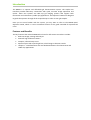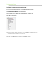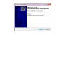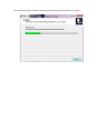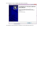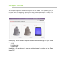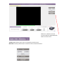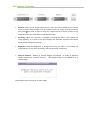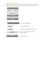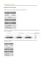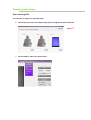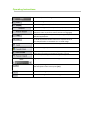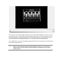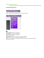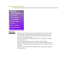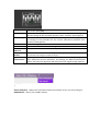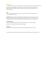
1
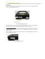
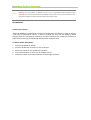
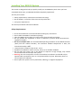
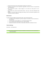
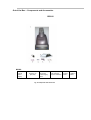
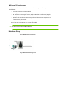
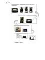
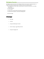
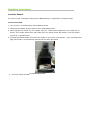
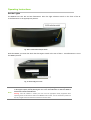
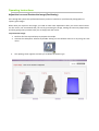
BIS910
Important Notice
© Copyright 2011 DNR Bio-Imaging Systems, Ltd All rights reserved.
The information contained in this document is proprietary and is subject to all relevant
copyright, patent, and other laws protecting intellectual property, as well as any specific
agreement protecting DNR Bio-Imaging Systems, Ltd. (DNR) rights in the aforesaid
information. Neither this document nor the information contained herein may be
published, reproduced, or disclosed to third parties, in whole or in part, without the
express, prior written permission of DNR. Such information is supplied solely for the
purpose of assisting explicitly and properly authorized users of the BIS910.
DNR reserves the right, without prior notice or liability, to make changes in
equipment design or specifications.
The text and graphics are for the purpose of illustration and reference only. The
specifications on which they are based are subject to change without notice.
Information in this user guide is subject to change without notice. Corporate and
individual names and data used in examples herein are fictitious unless otherwise
noted.
The software described in this user guide is furnished under license. The software may
be used or copied only in accordance with the written permission of DNR Bio Imaging
Systems.
Other company and brand products and service names are trademarks or registered
trademarks of their respective holders.
This document may contain flaws, omissions, or typesetting errors; no warranty is
granted nor liability assumed in relation thereto unless specifically undertaken by
DNR sales, contract, or order confirmation. Information contained herein is
periodically updated and changes will be incorporated into subsequent editions. If
you have encountered any error please contact DNR.
Contact us at: +972-2-570-0818
USA Toll-free number: 1-866-300-4286
email: [email protected]
Table of Contents
Introduction
Features and Benefits
Topics Covered
6
6
7
Hardware System Overview
8
Installing BIS910 System
Safety Requirements
Maintenance
Electrical Ratings
Out of the Box – Components and Accessories
Minimum PC Requirements
Hardware Setup – 2 Configurations
15
15
16
16
17
18
18
BIS910 Work Flow
19
GelCapture Installation Windows 7
21
GelCapture Installation XP Pro
25
Camera Driver Installation Windows 7
28
Camera Driver Installation XP Pro
37
GelCapture Overview
Icons
40
41
Operating Instructions
Insert the Sample
Set the Lights
Adjust the Lens and Preview the Image
Setting Camera Exposure, Sensitivity & Brightness
Saving the Image
Capturing a series of images
Open Image File
Using Imaging Tools
Inverted Image
Pseudo-color
Over-exposure
47
47
48
50
55
56
59
60
65
68
69
69
Troubleshooting
73
Glossary
74
Introduction
The BIS910 is a superior and affordable gel documentation system. The simple user
interface provides laboratory researchers with quick, accurate image acquisition and
results. These two systems are table top gel imaging systems that support both
fluorescent and colorimetric (visible dye) applications. This Operator’s Manual is designed
to guide the operator through all the required steps in order to scan gel samples.
Once you are more familiar with the system, you may want to refer to The BIS910 Quick
Reference Guide, which is a more condensed version of this guide intended for experienced
users.
Features and Benefits
The key features that make the BIS910 the choice for life science researchers include:
• Real time image, viewing and analysis.
• Scientific high resolution camera.
• Compact, safe and easy to use.
• Superior optics with super bright lens, which brings to ultimate results.
• Unique D – Transilluminator with two dedicated drawers for Fluorescence and
visible dye applications.
Introduction
This User Guide is one of two documents packaged with your BIS910 system. To better utilize
your system read the next chapter, “ Installing Your BIS910 System,” before proceeding to the
rest of the guide. Once your system is installed and operational, you can then familiarize
yourself with the system’s different features and procedures.
Everything you need to know about your BIS910 system is included in this guide. Pay special
attention to the highlighted chapters below. They contain information that you may need to
refer to in your day-to-day use of the BIS910 system.
Topics Covered
Chapter
An introduction to the manual and the topics covered Introduction
1
An introduction to the BIS910 and the GelCapture
software.
Hardware and software
2
Hardware installation instructions and configurations Installation procedures
3
Work Flow
BIS910
4
Installation procedures
Software and drivers
5
Step-by-step Operating Instructions
Capturing, saving, imaging
tools etc.
6
A listing of the most common issues and how to
resolve each
Troubleshooting
7
A list of terms used in this guide and their definitions. Glossary
8
Hardware System Overview
Each compactly designed BIS910 contains a high-resolution camera and GelCapture software
to provide the perfect solution for high quality imaging results. The BIS910 Imager is a userfriendly, high sample imaging tool.
The BIS910 is constructed of two components: a camera tower and a D-Transilluminator
which provides UV and White Light lower illumination. GelCapture also previews and saves
the scanned images, which are then exported for analysis. Configurations can also be saved
and later recalled for use with future samples.
The BIS910 Unit
The BIS910 comprises of the following main components:
Tower
D-Transilluminator
Fig. 1 BIS910
Hardware System Overview
BIS910
Camera Tower
The BIS910 camera tower holds a high-resolution camera. It connects directly to a PC through
its attached 2.0 USB compliant cable. The camera tower sits on the D – Transilluminator. A
vertical empty chamber extends directly below the camera providing the measured distance
between the camera, lens and the D-Transilluminator where the sample image is captured.
BIS910 Camera tower
D-Transilluminator
Fig. 2 BIS910
In order to prepare the BIS910 for operational use, the user must connect the following
cables:
•
The USB 2.0 cable: from the camera tower to the PC.
•
The Interlocking cable between the camera tower and the D – Transilluminator.
•
The D - Transilluminator Power supply cable from the D – Transilluminator to the
electrical socket
Hardware System Overview
D-Transilluminator
Fig. 3 D-Transilluminator
The D-Transilluminator can be used by itself as a standalone system or with the camera
tower.
The D-Transilluminator is provided for use with two interchangeable drawers, one for white
light (WL) and one for ultraviolet (UV) light. However when the BIS910 operates on Dual-UV
(see details on Page 15 below), the UV drawer must be used with a visible dye converter (see
Visible Dye Converter on Page 14 below). The Light Selection Switch is located on the front
panel of the D-Transilluminator.
This lower, D-Transilluminator unit is designed for maximum safety, ensuring that personnel
are not exposed to harmful light. This integral safety feature assures you that if the BIS910
door or drawer is opened, there is automatic light cut-out. The light only turns on following
correct insertion of the drawer and after the BIS910 door is closed.
D-Transilluminator
WL Tray
On/Off – WL/UV
Fig 4 D-Transilluminator – Front View
Illumination Switch
Hardware System Overview
Rear View
The back panel of the D -Transilluminator holds the cable connections, the Power On/Off
switch, and the BIS910 Bypass switch.
Fig. 5 D-Transilluminator - Rear View
After connecting all the cables and setting the BIS910 Bypass switch to the appropriate
position, the user should then advance to the GelCapture operation section.
Operating the BIS910 Bypass: When the D-Transilluminator is used by itself as a standalone
system the BIS910 Bypass switch should be set to the Bypass position before preparing for
image acquisition.
When the BIS910 is combined with the D-Transilluminator, the BIS910 Bypass switch should
be set to the BIS910 position.
Fig.6 BIS910 Bypass Switch
Hardware System Overview
Note:
The D–Transilluminator may be used as a stand-alone transilluminator.
Warning: since UV radiation is harmful, the user must use appropriate safety equipment when
operating the D-Transilluminator without the BIS910 camera tower. The user should also protect his
eyes when using WL intensive illumination without the camera tower.
Accessories
Visible Dye Converter
While the BIS910 is provided with the Dual UV configuration (see details on page 15 below),
it has only UV illumination sources. In order to provide the user with the ability to detect
samples which are stained with visible dyes, the user should use the visible dye converter as
required for converting and detecting samples under UV illumination.
To Detect Visible Stained Gels
1
2
3
4
5
Pull out the BIS910 UV drawer.
Place the Visible Dye Converter on the UV drawer.
Place your sample on the Visible Dye Converter.
Turn the illumination on from one of the light sources.
Continue to work as you would without the white light converter.
Hardware System Overview
Fig. 12 Visible Dye Converter
Dual UV Configuration
The standard D–Transilluminator is equipped with single type of UV and a single type of white
illumination source. Upon user request, we can implement a second type of UV source. e.g.:
We can supply two of the following options: 254 nm; 312 nm; 365 nm.
Implementing these two kinds of UV sources is defined as Dual UV configuration.
When you use the Dual UV configuration, the D–Transilluminator lacks white light sources.
Therefore you will have to use the White Light converter in order to detect samples which
are stained with visible dyes. Refer to the Visible Dyes Converter immediately above this
section. The BIS910 will be provided only with the UV drawer and the Visible Dye converter
(beside of the White Light drawer).
Installing Your BIS910 System
This section is designed to help you quickly install your new BIS910 system. Once you have
completed these steps, your BIS910 should be completely operational.
The first part reviews:
• Safety requirements, maintenance and electrical ratings
• Out of the Box: a visual list of the items in the product box
• PC system requirements
The second part details software installation.
Safety Requirements
•
•
•
•
•
•
•
•
•
•
Ensure that all devices are turned off before making any connections.
Do not block the BIS910’s ventilation openings.
Place the BIS910 at least 30cm (12 inches) away from the walls and ceiling.
Do not position the equipment so that it is difficult to perform device disconnection
(appliance coupler).
Do not store below 10ºC. The recommended operating conditions for the BIS910 are 25ºC
(78ºF) and 55% relative humidity. The maximum ambient temperature is 28°C; the
maximum humidity is 80%.
Transportation conditions: Ship at 10º - 25 º C.
Equipment intended for indoor use only, and up to an altitude of 2000m.
Do not open the system. Due to the danger of exposure to high voltage, only trained
service technicians should open the system.
Warning! The unit incorporates a source of hazardous UV radiation and should only be
operated with a protective cover or a UV protective filter in place. Otherwise, there is a
risk of exposure to radiation.
Do not place the system near any motorized, vibrating, or magnetic equipment.
• Verify that all devices are turned off before making any connections
• Equipment protection can be impaired if equipment is used in a manner not specified by
the manufacturer
• Do not store the system in direct sunlight or in the direct air flow path of an airconditioner.
• Do not clean the system with harmful solvents. Use only a soft cloth dampened with
water.
• Dispose of all plastic bags and wrapping according to local environmental regulations and
keep them away from children.
Maintenance
In order to keep the BIS910 in good working order, take the following steps:
•
•
•
•
The BIS910 must be cleaned every time a sample is removed. Use a soft non-abrasive,
lint-free cloth.
To clean all parts of the BIS910, use a cloth dampened with water.
Do not operate while wearing gloves with talcum powder.
Calibrate the camera once a year, as described in the Camera Calibration section
Electrical Ratings
100– 240 V ~ 50 / 60 Hz 0.6 A
Note: Before performing maintenance on any part of the BIS910, turn off the power to the D-Transilluminator,
and connected devices.
Out of the Box – Components and Accessories
BIS910
BIS910
1 7.5
Volt DC
Power
Supply
3
Drawers (2)
[WL/UV]
4 Transilluminator
Power Supply
Cable
5. GelCapture
and GelQuant
Express Software
Fig. 13 Components and Accessories
6. Interlocking
Cable
7
USB 2.0
Cable
Minimum PC Requirements
In order to install and operate both the BIS910 and the GelCapture software, you must have
the following:
Processor: Pentium Core Due, 1.8 GHz
Memory: minimum 1 G RAM, recommended 2 G RAM
OS: Windows XP Pro (English version, SP 3) OR Windows 7 Professional (English
version).
• Only PCs with a 32 bit operating system and local Administrator permission at a
minimum for the software installation process. After the installation, there is no need
of Administrator permission.
• Minimum monitor resolution: 1024 x 768 pixels
Port: 1 free USB 2.0 (USB 1.0 or 1.1 are not compatible
•
•
•
Note: User must set the PC settings to “Never Hibernate”
Hardware Setup
Fig. 14 BIS910Hardware Configuration
Fig. 15 BIS910 Hardware Configuration
Work Flow
Fig. 16 BIS910 Work Flow
Software Installation
GelCapture Software Installation for Windows 7
Once you have set up the hardware, you can install all of the required software.
To install GelCapture for Windows 7 proceed as follows:
Insert the CD into your PC and right-click the”GelCapture.exe” installation file.
Select “Run as administrator”.
When the next window appears, select “Allow, I trust this program. I know where it's from
or I've used it before” to allow the program to run.
Click “Next” in the 'Welcome to the GelCapture Setup Wizard' window.
The installation progress window will be displayed with the green progress bar in motion.
Once installation has been completed, click “Finish” to exit Setup.
The GelCapture capturing software for Windows 7 is now installed and ready to use.
Installing GelCapture for Windows XP Pro
Insert the CD into your PC and click “Next” in the 'Welcome to the GelCapture BIS910
Setup Wizard' window.
Once installation has been completed, click “Finish” to exit Setup.
The GelCapture capturing software for Windows XP Pro is now installed and ready to use.
BIS910 Camera Driver Installation
Installing the Camera Driver for Windows 7
The camera driver is pre-installed in the BIS910. If however, the user finds that this is not
the case, he should install it by following these instructions.
Before installing the camera driver, you must first install GelCapture software on your
computer.
Go to the Windows Control Panel by clicking Start >> Control Panel.
Open the "Hardware and Sound'
Open the 'Device Manager' under 'Devices and Printers'.
Connect the USB 2.0 imaging system between the system and the PC, and turn on the
imaging system camera. The device manager should recognize the new device connection
and alert you.
Under “Other devices”, right-click “Unknown device” and select “Update Driver Software”.
In the “Update Driver Software” window, select "Browse my computer for driver
software".
Select "Let me pick from a list of device drivers on my computer".
Choose “MiniBIS USB camera- 13S2M” and click 'Have Disk'.
In the “Install From Disk” window, click “Browse”.
Browse the following location: Computer > Local Disc (C) > Program Files > DNR >
GelCaptureBIS910 > drivers > PgrUsb and click 'Open'.
Choose MiniBIS from the PGRUSBCam.inf, and click “Open”.
Click “OK”.
Choose “MiniBIS USB camera- 13S2M” and click “Next”.
After successfully completing the driver update, the successful update window will be
displayed. Click “Close”.
Close the Device Manager and Control Panel windows.
The BIS910 camera driver is now installed and ready for use.
Installing the Camera Driver for Windows XP Pro
The camera driver is pre-installed in the BIS910. If however, the user finds that this is not
the case, he should install it by following these instructions.
Before installing the camera driver, you must first install GelCapture software on your
computer. Turn the BIS9010 unit on. Windows XP Pro automatically displays the “Found
New Hardware Wizard”. Choose “No, not this time” and click “Next”.
While the Wizard installs the drivers, the following window will be displayed:
If the Windows Logo testing window is displayed, choose “Continue Anyway”.
Once the Wizard completes the driver installation, click “Finish”.
Close the Device Manager and Control Panel windows.
The BIS910 camera driver is now installed and ready for use.
GelCapture Overview
The GelCapture application seamlessly integrates with the BIS910. The application gives you
complete control of configuring, capturing, and saving your sampled images for analysis. The
interface shows all of the features and tasks on the main screen.
In the entry screen you are required to select between the type of light source
you wish to use:
1. UV
2. White Light
3. Blue Light
In addition, you can chose to open an existing image by clicking on the “Open
Image File”
Menu bar, Toolbar icons and
Function Buttons explained below
Main UV Screen here:
Toolbar Icons: Allows quick access to frequently used functions.
Menu Bar: The drop-down menu contains all of the software features.
GelCapture Overview
•
Exposure: Refers to the image exposure time. This is the time available for the camera
sensor to collect emitted light from the sample to form an image. Increased exposure
time means more time for light to reach the camera sensor to display sections of the
image that were not visible with a lower exposure time
•
Sensitivity: When the sensitivity is changed by moving the slider, it will change the
image lightness. As a result of the Gain changes, the maximum exposure time will be
automatically changed accordingly.
•
Brightness: When the Brightness is changed by moving the slider, it will change the
image lightness (it acts more sensitively than the Sensitivity parameters).
•
Area of Interest - Defines a specific Region of Interest in order to perform
various actions on a specific area of the sample either in Live Mode or in a
saved image
Please adjust the focus and iris for each image.
GelCapture Overview
Icons
The most common tasks and features can usually be accessed with a single click of a button.
Saves newly scanned images
The image will be printed
Expoerts the image to BMP or JPG file formats
Opens the image in the analysis software
(GelQuant Express)
Opens the edit screen
various options of capturing a series of images
GelCapture Overview
The BIS910 system requires that you configure and fine tune in order to optimally acquire an
image of each different sample type. This process involves the following steps:
1. Pre capturing verification steps (Transilluminator and camera switches turn on, drawer
type choice)
2. Insert the Sample
3. Set the Lights
4. Adjust the Lens and Preview the Image (Positioning)
5. Set the Camera Exposure, Sensitivity and Brightness
6. Save the image
Additional actions:
• Print
•
Flat Field
•
Analysis
•
Using the White Light converter
•
Save an Image in jpg and bmp formats
•
Using the Imaging Tools
Operating Instructions
Insert the Sample
The very first step, inserting the sample on the BIS910 drawer, is completed in a few quick steps.
To insert the sample:
1. Turn on the D – Transilluminator and the BIS910 camera.
2. Check that the BIS910 - Bypass switch is set to the BIS910 position.
3. Select appropriate drawer for your sample stain (for a fluorescence application you should use UV
drawer; for a sample which stains with visible dyes you should use the WL drawer). Insert the drawer
into the D – Transilluminator.
4. Pull open the BIS910 drawer and locate the sample on the center of the drawer. If the transilluminator
light was turned on, it automatically switches off as a safety precaution.
Fig. 18 BIS910 Drawer Open
5. Close the drawer and door.
Operating Instructions
Set the Lights
The BIS910 has Trans WL and UV illumination. Press the light selection switch on the front of the DTransilluminator to the appropriate position.
Fig. 19 D-Transilluminator WL/UV Switch
With the BIS910, you must also check that the Bypass switch at the rear of the D - Transilluminator is set to
the BIS910 position.
Fig. 20 BIS910 Bypass Switch
Note:
The D–Transilluminator may be used as a stand-alone system by setting the BIS910 – Bypass switch
to the 'Bypass' option, thereby allowing the user to turn the illumination on while the BIS910 is
located next to the D-transilluminator.
Warning: since UV radiation is harmful, the user must use appropriate safety equipment when
operating the D-Transilluminator without the BIS910 camera tower. The user should also protect his
eyes by using WL intensive illumination without the camera tower.
Operating Instructions
Adjust the Lens and Preview the Image (Positioning)
Even though the system uses professional lenses you do not need to be a professional photographer to
capture great images.
Often when you capture a new image, you need to make some adjustments after you see the initial results.
For this reason, we recommend that you start by previewing the image, making the necessary adjustments,
and then getting more previews until you are happy with the results.
To preview the image:
1. Perform all of the required steps to prepare the sample.
2. Activate the GelCapture software by double clicking on the software shortcut or by using the start
menu.
3.
The opening screen appears and asks you to define the drawer type.
Operating Instructions
The software will be opened in Preview position.
gggg
Operating Instructions
While you are in Preview mode, finger-tip adjust the following dials which are located in the BIS910 camera
tower:
Iris: Adjust it till you reach satisfactory image illumination. It is recommended to activate the 'Over Exposure
icon (see Page 80 for using over-exposure).
Close position: the iris is close and minimum light will go from the sample to the camera.
Open position: The iris is open, and maximum light will go from the sample to camera
Focus: Adjust this dial in order to obtain a fully, focused image.
For professional focus adjustment, you can use the Histogram bar in the Edit screen (see image below
pointed with a red arrow).
Slide the focus slide bar till you obtain the ultimate Edge number. Adjust the focus until the Edge reading is at
its highest: The higher the number, the sharper the image.
The user should be aware that every image and every sample in a given illumination intensity will have a
different Edge number.
If you are not happy with the results, you can revert the results received after adjusting the histogram by
selecting Restore Original (see image below pointed with a green arrow).
Histogram Bar
Operating Instructions
Set the Camera Exposure, Sensitivity and Brightness
Set the exposure time by moving the sliders to the appropriate exposure time until you can clearly
detect your sample.
Set the Sensitivity
Sensitivity is a feature which amplifies the signal emerging from your sample. A higher GSensitivity setting will
result in a brighter image.
As this feature amplifies any signal from the image, you may see some background noise.
Since it is preferable to maintain a dynamic image range, increasing the Sensitivity parameters will decrease
the maximum exposure time.
Set the Brightness
Increasing the Brightness will result in a brighter image. Increasing the Brightness parameters will provide a
less dramatically image brightness effect than the Gain.
Operating Instructions
Saving the Image
GelCapture allows you save images in .TIFF, .BMP and .JPEG formats. You should be aware that tiff format
saves all the raw data of the image, and it is highly recommended to choose this format while intending
to analyze a given image. Other formats save only part of the image information, and therefore provide
less accurate results from image analysis process.
Saving options:
a. Saving a single image:
Saving image in tiff format:
After determining the settings for an image and if you are happy with the results, you should save the image
by choosing one of the following buttons:
Or
Clicking on each one of the above buttons will display a pop up save image dialog as shown below:
You should provide an image name at the 'File name' section.
Operating Instructions
1.
Notes:
2.
The tiff format saves all the image raw data. As a result, the image sizes are slightly bigger
(several MB). If you would like to save the image in a lighter format, save it as BMP / JPEG
format. You should be aware that while using analysis software it is highly recommended to
use images in tiff format to gain accurate results.
While saving images in BMP / JPEG formats, these saving options are eliminated.
3. Some PC's lack the ability to automatically open 16 bit tiff files format, as captured with
the BIS910. If you want to save an image for other reasons than analyzing it, you can save it
in BMP / JPEG format which can be opened in most of the PC's.
Saving the Image in BMP / JPEG Formats
If you would like to save the image in a lighter image size than the tiff format, you can choose either BMP or
JPEG formats. You should be aware that DNR highly recommends analyzing only images which are saved in
tiff format.
In order to save the image in these formats you need to select the Export Image option. There are 2 possible
ways to do so; please see below image.
A. Now you can choose at the Save Dialog screen between the BMP and JPEG formats.
Operating Instructions
Capturing a series of images
In order to capture a series of images select Multi Images Acquisition
You need to set the number of images you wish to capture. The exposure time is determined by moving the
scales (see image below).
In addition it is possible to create a repetition rule by marking the “Repeat every” button. The time is
determined by the user.
Operating Instructions
Open an Image File
You can open an image in two possible ways:
1. On the opening screen, select Open Image File (see image below with red arrow)
2. On the Toolbar, select File> Open Tiff File
Operating Instructions
When a user opens image/images, the following screen will be shown.
Operating Instructions
Saves newly scanned images
Prints the image
Save the image in BMP/JPG file formats
Opens the image in the analysis software (GelQuant Express)
The Area of Interest feature lets you define a specific area of the
sample in order to perform various actions on itfggtgttgt
Copies the image to the clipboard for pasting in any number of
Window applications
Defines a specific Region of Interest in the Preview Screen
in order to perform various actions on a specific area of
the sample either in Live Mode or in a saved image
Presents an inverse version of the image
Shows the image in pseudo colors
Automatically increases the stretching of the image. This option helps
reveal low concentrations of biological samples in the gel.
Restores any stretching actions to the original image values.
Digitally zooms in and out to the image.
Displays the image so that it fills the entire screen. To return to
the GelCapture main screen press [Esc].
Presents the image in its actual size.
Resizes the image to fit within the image window.
In some cases the resulted image provides only part of the expected bands. In order to reveal
more bands if any, you may use the Automatic stretching button. It will automatically stretch
the image signals by a software algorithm, and will reveal some low intensity bands. You can
also use the Contrast Low/High level sliders, as a manual, software stretching action.
If you would like to return to the original image parameters after stretching, you should click on
the 'Restore Original' button.
Note:
User should be aware that if you make stretching changes to the image and then save them, those
changes are saved with the image when opened in GelCapture. If however, you open the same
stretched image in any other software apart from GelCapture, the image appears as it did when
originally captured.
Operating Instructions
The image statistics is presented above the image to the left
Operating Instructions
Using the Imaging Tools
Home – Clicking on this button will take you to the opening screen.
File
Open Tiff Image – Opens a saved image
Save Image – Saves newly scanned images
Export Image – Saving image in BMP/JPG
Print – Prints the image
Print Preview – Allows you to preview the print before printing
Page Setup – Allows you to arrange the print before printing
Copy – Copies the image to the clipboard for pasting in any number of Window applications
Exit – Exits the software
Operating Instructions
Preferences
Area of interest
Defines an area of interest. A green frame will appear on screen, as seen in
the below image. Adjust the image size or position. You can either stretch
the pivot points on the frame or mouse-left click and drag down to open a
new frame of a region of interest.
Place the cursor anywhere within the green frame and right click to display
the menu options.
A green frame will appear on screen, as seen in the below image.
Adjust the image size or position. You can either stretch the pivot points on
the frame or mouse-left click and drag down to open a new frame of a region
of interest.
Place the cursor anywhere within the green frame and right click to display
the menu options.
Full screen
Save Settings
Load Settings
Pseudo Color
Invert
Over
Exposure
Contrast
Stretch
Optical
Enhancement
Displays the image so that it fills the entire screen. To return to the GelCapture
main screen press [Esc].
If you wish to save a procedure for future use, clicking on Save Settings, will
save the settings of the proceudre (exposure time, sensitivity and brighness)
If you wish to work with a saved procedure, clicking on Load Settings, will set
the settings of the proceudre for this current experiment (exposure time,
sensitivity and brighness)
Shows the image in pseudo colors
Presents an inverse version of the image
Shows in red those areas that are overexposed.
Automatically increases the stretching of the image. This option helps reveal low
concentrations of biological samples in the gel.
The image presented both in UV and WL is processed through an algorithm
which eliminates the lens distortions. Un-checking the Optical Enhancement
button, will cancel the algorithm and will present the original image captured.
?
About GelCapture -displays the information about the software version you are working on.
DNR Website – directs you to DNR’s website.
Operating Instructions
Inverted Image
An inverted image shows the image with the color scale inverted: light areas appear dark, and
dark ones appear light, much like a negative. This feature is useful in such scenarios as helping
the user to decipher dark areas.
Inverted Image
Inverted image inverts the color scale, i.e., light areas appear dark and dark areas appear light,
much like a negative. This feature is particularly useful when you need to decipher close bands.
To Invert an Image
Click the Invert Image icon
. Click the icon again to revert to original
view of image. You can also view an Image in invert position by selecting Preferences> Invert
Pseudo-color
To View an Image in Pseudo-color
Click the Pseudo-color icon.
Click the Pseudo-color icon again to revert to the original view of the image.
You can also view an Image in Pseudo-color by selecting Preferences> Pseudo Color
Overexposure
Overexposure occurs when the camera receives too much light, which usually results in white
or bright areas. This phenomenon leads to inaccurate results when analyzing the image
information. In order to avoid this distortion, GelCapture is equipped with the Overexposure
tool which displays overexposed areas in red.
To View an Image Using the Overexposure Tool
Click the Overexposure button.
Unclick the Overexposure button again to revert to the original view of the image.
You can also view an Image in over exposure by selecting Preferences> Over Exposure
Troubleshooting
Before you contact support, it is recommended that you read over this section to see if you
can resolve the problem by yourself. To make this as easy as possible, we have created a list
of the most common problems and their possible solutions.
I don’t see any image on the screen.
Try one of the following:
• Make sure that the Transilluminator is turned on.
• Wait a few seconds. Each time the settings change, it takes time for the image to be
displayed.
• If you are working with White Light, then check that the iris is slightly closed. Move
the Iris dial toward the Close side to reduce the amount of light entering the iris. If
you are working with UV light, the iris should be almost completely opened. Move
the Iris dial toward the Open side to increase the amount of light entering the Iris. If
it is a very dark sample, the iris can be completely opened
• Check that the lighting conditions are satisfactory.
The image is out of focus.
Check that the focus is set with its center mark aligned with the center mark on the
BIS910.
The frame counter is progressing, but the picture is black.
• Check that the light on the Transilluminator table is switched on.
• Verify the iris position. When working with UV light, the iris should be almost
completely opened. If it is a very dark sample, the Iris can be opened all the way.
The image quality is poor.
Recalibrate the camera as explained in the Camera Calibration section of the Installation Guide.
Please note that this takes at least 40 minutes to complete
Glossary
CCD
The CCD (charge-coupled device) is a major piece of technology in digital imaging. In a CCD
image sensor, pixels are represented by capacitors. These capacitors are based above the
threshold for inversion when image acquisition begins, allowing the conversion of incoming
photons into electron charges at the semiconductor-oxide interface; the CCD is then used to
read out these charges. Although CCDs are not the only technology to allow for light detection,
CCD image sensors are widely used in professional, medical, and scientific applications where
high-quality image data is required.
Dynamic Range
The range that a sensor is capable of differentiating. If the sensor can differentiate between
two points in an image, then each point is translated into a pixel of the image; if the sensor is
not able to differentiate, then the two points will be pixels of noise. Dynamic Range is also
referred to as Signal to Noise Ratio (SNR).
Exposure Time
The length of time that light is allowed to pass through to the camera lens to form an
image.
Fluorescence
The process whereby a fluorescent molecule is excited at one wavelength and
immediately re-emits it at another (longer) wavelength.
Gain
Gain is a camera feature which increases or decreases the strength of an electrical signal.
When the gain is increased the image’s brightness also increases, but so does any electronic
“noise”. This results in a brighter image with less clarity.
Glossary
Iris: A mechanical diaphragm which adjusts the lens aperture. When there are high levels of
illumination then iris should be closed, and when there are low levels of illumination the iris
should be opened.
Pixel
A pixel, or picture element, is the basic unit that the camera uses to build an image. Image
size is also measured in pixels.
Pseudocolors: Illustrates the levels throughout the sample’s image. The cooler colors, such as
blue indicate where the image is undersaturated, and the hotter colors, such as yellow or red,
indicate where the image is oversaturated. Green indicates the levels are in the mid-range.
Quantum Efficiency
A measure of the efficiency by which photons generate electrons in a pixel. The Q/E is
function of the camera sensor in regards to wavelengths.
Resolution
Although definitions vary, the most common one is the number of pixels on a camera.