1
Archive Writer
Interface Software
User’s
Guide
A-61056
Part No. 3E9644
CAT No. 881 4832
EASTMAN KODAK COMPANY
SOFTWARE LICENSE AGREEMENT
Read the following terms and conditions carefully before using this Software. Use of this Software indicates
your acceptance of these terms and conditions. If you do not agree with them, you should promptly return the
package in its entirety for a full refund.
LICENSE
Grant of License. Eastman Kodak Company ("Kodak") grants you a license to use one copy of the enclosed software
program(s) (the "Software") subject to the license restrictions set forth below.
Restrictions on Use. You may use the Software only on one computer at a time. For each additional computer on which
the Software is running at the same time, you will need an additional licensed copy of the Software. You may copy the
Software as necessary to enable you to use the Software as described above.
Transfer of the Softw are. You may permanently transfer the Software to another party if the other party agrees to accept
the terms and conditions of this license and you retain no copies of the Software.
Copyright. The Software is owned by Kodak or its suppliers and protected by copyright laws and international treaties.
You may not copy the Software other than as expressly provided in this license. You may not reverse engineer,
decompile, or disassemble the Software. If this Software is used within a country of the European Union, nothing in this
Agreement shall be construed as restricting any rights available under the European Community Software Directive
(91/250/EEC).
Term. This license is effective until terminated. You may terminate it at any time by destroying the Software together with
all copies in any form. It will also terminate if you fail to comply with any term or condition of this Agreement. You agree
upon such termination to destroy the Software together with all copies in any form.
LIMITED WARRANTY
For a period of 90 days after the date of delivery of the Software to you, as evidenced by a copy of your purchase receipt,
Kodak warrants (i) the Software will perform substantially in accordance with the accompanying written materials, and (ii)
the media on which the Software is furnished will be free from defects in materials and workmanship under normal use.
Kodak does not warrant that the functions contained in the Software will meet your requirements or that the operation of
the Software will be uninterrupted or error free. You assume responsibility for operation of the Software to achieve your
intended results, and for the installation, use, and results obtained from the Software.
Subject to any applicable legislation which prohibits the following exclusions, KODAK MAKES NO OTHER WARRANTIES
OF ANY KIND, EITHER EXPRESS OR IMPLIED, INCLUDING THE IMPLIED WARRANTIES OF MERCHANTABILITY
AND FITNESS FOR A PARTICULAR PURPOSE. Some states and countries, including Australia, do not allow the
exclusion of implied warranties, or have legislation that imposes certain statutory warranties that cannot be excluded, so
the above exclusion may not apply to you. This warranty gives you specific legal rights and you may also have other
rights.
LIMITATIONS OF REMEDIES
Subject to any applicable legislation which prohibits the following limitations, Kodak's entire liability and your exclusive
remedy shall be, at Kodak's option either (a) the repair or replacement of the Software or any media not meeting Kodak's
"Limited Warranty" that is returned to Kodak or your dealer with a copy of your receipt, or (b) the return of the price you
paid for the Software, provided you have proof of the purchase price you paid. These remedies are not available if failure
of the Software or media si the result of misuse, abuse, or a failure to follow the operating instructions in the
accompanying written materials.
IN NO EVENT WILL KODAK OR ITS SUPPLIERS OR DEALERS BE LIABLE TO YOU FOR ANY INCIDENTAL OR
CONSEQUENTIAL DAMAGES, INCLUDING ANY LOST PROFITS, LOST SAVINGS, OR OTHER DAMAGES ARISING
OUT OF THE USE OR INABILITY TO USE THE SOFTWARE EVEN IF ADVISED OF THE POSSIBILITY OF SUCH
DAMAGES. Some states and countries, including Australia, do not allow the limitation or exclusion of liability for
incidental or consequential damages, or have legislation which restricts the limitation or exclusion of liability, so the above
limitation may not apply to you.
GENERAL
If the Software was purchased in the United States, this Agreement is governed by the laws of the State of New York. If
purchased outside the United States, this Agreement is governed by the laws of the country in which it was purchased.
U.S. GOVERNMENT RESTRICTED RIGHTS
The SOFTWARE and documentation are provided with RESTRICTED RIGHTS. Use, duplication, or disclosure by the
Government is subject to restrictions as set forth in subdivision (c)(1)(ii) of The Rights in Technical Data and Computer
Software clause DFAR 252.227-7013 or such other applicable government or agency regulation providing equivalent
protection. Contractor / manufacturer is Eastman Kodak Company, 343 State Street, Rochester, New York, 14650.
1 Introduction
About this guide
The Kodak Imagelink Archive Writer Interface Software application
provides a high-level interface to the Kodak Digital Science Document
Archive Writer 4800 and the Kodak i9600 Series Writers. It also
provides a set of restricted functions for administrative tasks involved in
using the software.
Throughout this manual, the term Writer is used to describe both the
Kodak Digital Science Document Archive Writer 4800 and the Kodak
i9600 Series Writer. Any differences between the two Writers will be
noted. This guide contains information and procedures necessary for
setting up and running the Kodak Imagelink Archive Writer Interface
Software (AWIS).
Organization
In addition to this chapter, the AWIS User’s Guide is organized as
follows:
Chapter 2, Installing AWIS: Provides hardware and software system
requirements, instructions for installing an upgraded version of AWIS
and how to start and exit AWIS.
Chapter 3, AWIS Administration: Describes each screen in AWIS
Administration, including explanations of each field as well as
procedures on how to set up applications, Writers and film templates.
Chapter 4, AWIS Application: Describes each screen in AWIS
Application, including explanations of each field as well as procedures
on how to run a job.
Chapter 5, Troubleshooting: Describes problems you may encounter
while using AWIS and provides a list of error codes.
Appendix A, Input Modes: Provides detailed information and examples
regarding List files and Batch mode as well as information on how to
create a List file.
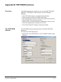
Appendix B, TIFFCHKR Functions: Provides information about the
TIFFCHKR function and how to use it.
Appendix C, Glossary: Provides a listing of terms associated with the
Writer and AWIS.
Appendix D, Index Formats, Image Addressing and Image Marks
Appendix E, Image File Specifications: details the specifications of the
digital image files to be written to film.
A-61056 March 2003
1-1
What is AWIS?
AWIS is a Microsoft Windows application that provides a fully functional
interface to the Kodak Digital Science Document Archive Writer 4800
and the Kodak i9600 Series Writer. It is intended for those customers
who do not want to develop their own application and whose needs do
not require that the functionality provided by the application be
completely integrated into their own existing software systems.
AWIS includes the following components:
AWIS Administration – allows access to all administrative
functions. See Chapter 3 - AWIS Administration, for more information.
• Creates and maintains applications and film templates that define the
film output (i.e., simplex, duplex, image marks, etc.).
• Defines the available Writers.
• Configures Poll mode.
• Configures performance parameters.
• Purges jobs.
• Generates reports.
AWIS Application – writes images using an application created
via AWIS Administration. See Chapter 4 - AWIS Application, for more
information.
• Controls and facilitates the transfer of image files from the imaging or
scanning system to the Writer.
• Provides a status of Writer operations.
• Provides job status (i.e., Completed, Verified, Waiting for input, etc.)
and verification.
• Generates the Transfer file that links the file name to the roll ID and
image address, which are used to index the images for future
retrievals.
• Generates reports.
TIFFCHKR Software – checks the image files before being
written to film to assure the images are compliant with what the Writer
and application definition expects. See Appendix B – TIFFCHKR
Functions, for more information.
• Checks if required TIFF tags are present and have acceptable
values.
• Checks if text files meet size restrictions or if they will be truncated.
• Validates compression format.
• Checks if the images meet scaling requirements and will fit across
the width of the film.
• Checks if the images are located where indicated in the List file or
Batch directory.
• Converts multi-strip images to single-strip images.
• Validates TIFF file size with the memory available on the Writer.
1-2
A-61056 March 2003
Awis.log – provides easy access to the Log file. See Chapter 3,
“Error Logging tab” for more information.
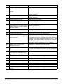
What you need to
know
Users of AWIS must understand the Microsoft Windows operating
systems, including basic Windows terms and functions, and the basics
of microfilm technology, especially image addressing.
For Windows, you must understand the following concepts; if you are
not familiar with these terms, it is recommended you use the manuals
accompanying your Windows software.
Getting technical
support
Button
Icon
Click
Mouse
Close
Program Manager
Dialog box
Pull-down menu
Double-click
Shift+click
Drop-down list
Single-click
Read this section before contacting Kodak for technical support.
The following information is needed when contacting Kodak technical
support for the AWIS Software. This procedure is current as of the date
of this guide, but it may change without notice as conditions require.
Response Center assistance is available as part of the Service Agreement. Refer to the Service Agreement Terms and Conditions for hours
of availability.
Only a trained System Administrator should place the call to the Kodak
Response Center. The following items will be requested:
• A K-number that identifies the AWIS Software.
• A brief description of the question or problem.
• A contact name and a phone number where the contact/customer
can be reached.
A-61056 March 2003
1-3
Phone numbers:
U.S. and Canada: 1-800-822-1414
International: 1-585-724-4675
The contact’s name and phone number will be taken by a Response
Center operator. A Response Center System Support Engineer will
return the call.
The goal is to answer inquires on the first call. However, depending on
the complexity of the question, it may be necessary to confer with other
technical resources. Therefore, the inquiry may require follow-up contact.
Before calling the Response Center:
• Make sure that you have checked your input TIFF files with the
TIFFCHKR application with the Multi-strip to Single-strip option
enabled.
• Make sure you have changed the battery in your film cassette.
1-4
A-61056 March 2003
2 Installing AWIS
System requirements
The following minimum hardware and software requirements are
required to run AWIS.
Hardware
• 300 MHz Pentium II processor
• 64 MB RAM (128 MB recommended)
• At least 20 Gigabytes (GB) hard drive or enough space to hold the
desired number of image files. It is recommended that the hard drive
is at least 2 ½ times the size of the largest job you are running.
• CD ROM drive
• Monitor, keyboard, mouse
• Ethernet adapter compatible with IEEE 802.3 Ethernet. 3Com
EtherLink III has been tested and is recommended for interfacing with
the Writer
• Cabling from PC to Writer
Software
Microsoft Windows NT, v4.0 Client and Server version with Service
Pack 4, Windows 2000 Client and Server.
Upgrading AWIS
Installing a new system requires other setup procedures, which are not
documented below. Professional services are available for installing a
new system. Contact your local Kodak Field Engineer for information
regarding the Kodak Imagelink Digital Document Archive System PreInstallation Accreditation.
If you want to upgrade AWIS from Versions 1.3 or greater, you can use
the following Windows procedure:
1. Place the AWIS CD in the CD drive.
2. From the Start menu, select Start > Run.
3. Type x:\setup where x is the letter of your CD drive.
4. Click OK.
5. Follow the instructions on the screen.
When the upgrade process is complete, icons for AWIS Administration,
AWIS Application, TIFFCHKR and AWIS.log will appear on the
desktop, as well as be displayed under the Programs menu.
NOTE: The Writer must be rebooted to activate any firmware changes
associated with this release.
A-61056 March 2003
2-1
Starting the software
To start AWIS:
1. In the Windows Start menu, select Programs>AWIS. The AWIS
menu contains the Archive Writer Interface Software (AWIS), AWIS
Administration, AWIS.log and TIFFCHKR.
2. Select the AWIS module you want to work with, AWIS
Administration, AWIS Application, TIFFCHKR or AWIS.log.
Refer to the following chapters for more information:
•
•
•
•
Exiting the software
2-2
Chapter 3, AWIS Administration
Chapter 4, AWIS Application
Appendix B, TIFFCHKR Functions
Chapter 3, “File menu – Error logging tab”, AWIS.log
From the File menu, select Exit.
A-61056 March 2003
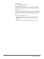
3 AWIS Administration
This chapter provides an overview of the windows you have access to
when using AWIS Administration, as well as procedures for setting up
applications, film templates, defining a Writer, removing jobs from the
system and printing a report.
See Chapter 4, AWIS Application for an overview of the windows in
AWIS Application and procedures for running jobs.
• From the Start menu, select Programs > AWIS Administration or
click on the AWIS Administration icon.
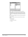
The AWIS Administration window is displayed.
The menu bar provides the following options:
File — allows you to set up applications, define Writers and film
templates, provides access to the Advanced and Polling tabs and exit
AWIS Administration.
Purge — allows you to delete a job and its associated files from the
system.
Reports — allows you to print a report of current AWIS jobs.
Help — provides access to AWIS Administration help.
A-61056 March 2003
3-1
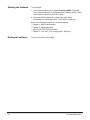
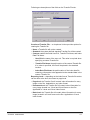
File Menu
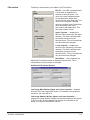
The File menu contains the following options: Applications, Archive
Writers, Film Templates, Options and Exit.
File menu —
Applications
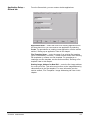
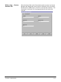
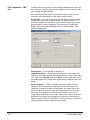
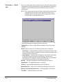
When you select Applications from the File menu, the AWIS
Application Setup window is displayed. This window contains the
following tabs: General, Begin Roll, End Roll, Transfer File, Error
Logging, and Input Mode. Each tab allows you to set up an aspect of
the application.
AWIS Application
Setup
The buttons on the bottom of the AWIS Application Setup window apply
to all of the tabs. If a button is grayed-out, it is not applicable for the
active tab.
OK: saves the values on the tabs and closes the window.
Save: saves the values on the tabs, but does not close the window.
Delete: when the General tab is active, the selected application can be
deleted. System-supplied default applications cannot be deleted.
Create : when the General tab is active, the Create New Application
dialog box is displayed.
Cancel: closes the window without saving any changes.
Procedures on how to create new applications can be found in this
chapter.
3-2
A-61056 March 2003
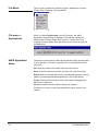
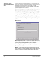
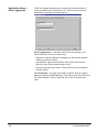
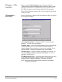
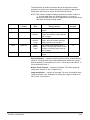
Application Setup —
General tab
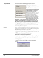
From the General tab, you can create or delete applications.
Application Name — select the name of an existing application from
the drop-down list or you can create a new application by selecting
Create . For procedures on creating a new application, see the section
entitled, “Setting up an application” later in this chapter.
Film Template Name — enter the name of an existing film template
(up to 24 characters) or use the … button to select from a list of existing
film templates or create a new film template. For procedures on
creating a new film template, see the section entitled, “Defining a film
template” later in this chapter.
Starting Image Address for New Roll — enter the first image address
for a new roll of film. This value must conform to the image addressing
values defined in the film template. For more information see the
section entitled, “Film Templates - Image Addressing tab” later in this
chapter.
A-61056 March 2003
3-3
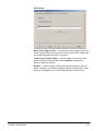
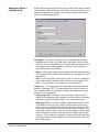
Application Setup —
Begin Roll and End Roll
tabs
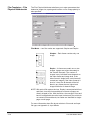
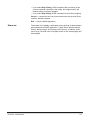
The Begin Roll and End Roll tabs allow you to configure header and
trailer page information. Header and trailer pages are images that can
be added to the beginning and end of a roll of film to provide
information such as the name of the job, responsible operator, date,
resolution targets and error or job logs.
Header and trailer pages are not assigned an image address, and the
frame containing them does not receive an image mark.
Each header and trailer page input file must be either a TIFF image file,
or a text file, that conforms to the Writer’s input file specifications. For
more information, see Appendix E, Image File Specifications. AWIS
converts any text files to TIFF format prior to writing to film. Header
page files should be kept in a different directory than trailer page files. If
a directory contains multiple files, the files within the directory are
sorted and written to film using the Windows file sorting algorithm, so be
sure to name the files accordingly in order to get the desired sequence
on film.
Begin Roll tab:
Write Header Pages to film — if checked, the header pages found in
the Header Pages directory are written to film at the beginning of each
roll prior to the first image designated via batch or list input.
Header Pages Directory Path — enter the path to a directory name
where the header images reside or select Browse to display the
Directory Selection window.
Browse — used to display the Directory Selection window. After you
select a directory, the window disappears and the full path name of the
directory is displayed in the Header Pages Directory Path text box.
3-4
A-61056 March 2003
End Roll tab:
Write Trailer Pages to film — if checked, the trailer pages found in the
Trailer Pages directory are written to film at the end of the roll after the
last image designated via batch or list input.
Trailer Pages Directory Path — enter the path to a directory name
where the trailer images reside or select Browse to display the
Directory Selection window.
Browse — used to display the Directory Selection window. After you
select a directory, the window disappears and the full pathname of the
directory is displayed in the Trailer Pages Directory Path text box.
A-61056 March 2003
3-5
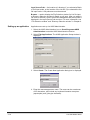
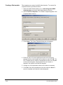
Application Setup —
Transfer File tab
The Transfer File tab allows you to specify creation of Transfer files and
configure the parameters associated with the Transfer files.
A Transfer file can be generated during the writing of images to film. It
contains indexing information that can be uploaded to an image
retrieval database. The location of each file is c:\Program
Files\AWIS\Apps\(Application Name)\(Roll ID). The filename will be
(Roll ID).xfr.
If a job spans more than one roll, the Transfer file for each subsequent
roll will be created in the same directory as the Transfer file for the first
roll. For example, when the transition from roll 1 to roll 2 occurs, the
Transfer file <2.xfr> will be created in the directory <1>.
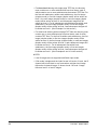
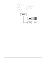
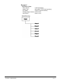
A standard or custom Transfer file can be generated. A standard
Transfer file provides a cross-reference of input filename to Roll ID and
image address. The page number within the input file is also listed. The
fields are separated by tabs. See the 2-level example below, using
page level reporting.
A custom Transfer file can be created via a user exit routine. This
provides the capability to append additional data to the information in
the standard Transfer file. For more information, see the KODAK
Archive Writer Interface Software, Integrator’s Guide, A-61057.
3-6
A-61056 March 2003
Following are descriptions of the fields on the Transfer File tab:
Creation of Transfer File — a drop-down list box provides options for
creating the Transfer file:
• None: a Transfer file will not be created.
• Standard: the system-defined standard Transfer file will be created.
• Custom: enables the fields User Exit, Transfer File Name, and Index
Data File Name.
- User Exit: the name of the user exit. This value is required when
specifying a custom Transfer file.
- Transfer File Name: the path location of the custom Transfer file.
If no value is specified, the file will be placed in the standard
location.
- Index Data File Name: the path location of the index data file
containing information to be appended to the standard data in the
custom Transfer file.
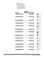
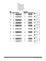
Reporting Level — depending on the index format, Transfer file entries
can be done at the book, document or page level.
• Page-level: the Transfer file will contain index information for every
image on the film. Applicable to any index format.
• Document-level: the Transfer file will contain index information for
every image located in a 3-level and 2-level frame on the film.
Applicable to 3-level and 2-level index format.
• Book-level: the Transfer file will contain index information for every
image located in a 3-level frame on the film. Applicable to 3-level
index format.
A-61056 March 2003
3-7
Application Setup —
Error Logging tab
The Error Logging tab allows you to select the level and number of
errors you want to post to the Error Log. The Error Log file can be
accessed by clicking on the AWIS.log icon.
Error Logging Level — provides a drop-down list allowing you to
select the level of errors you want to log.
• Diagnostic: logs all diagnostic messages, as well as informational,
warning, and severe errors.
• Informational: logs all informational, warning and severe errors.
• Warning: logs all warning and severe errors.
• Severe: logs only severe errors. These errors are serious and will
halt the system.
Trim Threshold — an entry in this field is required. Enter an integer
between 40,000 and 9,999,999 bytes. The oldest errors in the Error Log
file will be deleted in order to keep the size of the file less than this
value.
3-8
A-61056 March 2003
Application Setup —
Input Mode tab
AWIS reads image files from a disk drive (usually a drive that is shared
on the network) and sends them to the Writer. Input modes allow you to
sequence image files as desired on film. AWIS supports these input
modes: List file, Batch and Poll.
Input Mode — provides a drop-down list of supported Input Modes:
• List File: in this mode, the image files to be written to film must be
listed in a file using full pathnames. Files are read and written to film
in the same order as they appear in the List file. See Appendix A,
Input Modes for more information.
• Batch: in this mode, image files are read from the directory specified
in the Input Source Path field. See Appendix A, Input Modes for more
information.
• Poll: in this mode, AWIS searches for a Poll file, which is created by
some other means external to AWIS. See the section entitled, “File
menu – Options” later in this chapter for more information.
Image Type — the image type of the input files must be specified as
single- or multi-page TIFF. This value effects the layout of images on
film, especially when the film mode is duplex. See Appendix A, Input
Modes for more information.
• Single-page TIFF: file contains only one image. Images can be
written to film separately using single-level index format, or grouped
with other images and written using 2- or 3-level index format.
• Multi-page TIFF: file contains multiple images and each file can be
considered a two-level group. Images can be written to film using
single-level index format but the two-level grouping will be lost. Twolevel index format allows the two-level grouping to be retained. The
first image (simplex mode) or first two images (duplex mode) of each
file will be written as level 2, and subsequent images will be written
as level 1. This provides the capability to index and retrieve the entire
multi-page file as a group. Multiple files can be grouped using threelevel index format.
A-61056 March 2003
3-9
Input Source Path — the location of a directory if you selected a Batch
or Poll input mode, or the location of the List file if you selected the List
file input mode. A full pathname must be entered.
Browse — used to display the File Selection window for List file input,
or Directory Selection window for Batch or poll input. After you select a
file name or directory name, the window disappears and the full path is
displayed in the Input Source Path text box. For more information, see
“File Selection window” and “Directory Selection window” in Chapter 4.
Setting up an application
Applications are set up via AWIS Administration.
1. Select the AWIS Administration icon or Start>Programs>AWIS
Administration to start the AWIS Administration function.
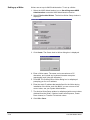
2. Select File>Applications. The AWIS Application Setup window is
displayed.
3. Select Create. The Create New Application dialog box is displayed.
4. Enter the desired application name. The name can be a maximum
of 25 characters, and include any keyboard character except an ‘
(apostrophe) and | (the pipe character).
3-10
A-61056 March 2003
5. Select a Based on Template from the drop-down list of existing
applications and click OK. All parameters from the selected
application are copied to the new application.
6. Change any of the copied parameters or set new parameters as
necessary on the other tabs. The fields on these tabs are described
earlier in this chapter.
7. Click OK to save the application and close the Application Setup
window or Save to save the application and keep the Application
Setup window displayed.
A-61056 March 2003
3-11
File menu — Archive
Writers
When you select this option, the Archive Writer Setup window is
displayed. This window contains a General and Version Numbers tab.
Writer setup — General
tab
The General tab allows you to set up a new Writer or modify or delete
an existing one.
Name — provides a drop-down list of Writers currently set up in the
system. Select an existing Writer from the list or if you want to set up a
new Writer, click Create to display the Create Archive Writer dialog
box. See the section entitled, “Setting up a Writer” later in this chapter
for procedures.
The following fields will contain a value only when a valid value is
specified in the name field.
Device Model — memory configuration of the Writer. Large or Small is
displayed; this value cannot be changed.
IP Address — the static IP address of the Writer is displayed; this
value cannot be changed.
Exposure — enter/select an exposure value from 5 to 50 to lighten or
darken the images on film. The default value is 14.
Power Down Interval in minutes — defines how many minutes must
pass without activity before the status display on the Writer goes into
power-saving mode. Value Range 00, 10 to 999 minutes. The disable
value is 0.
File Transfer Interval in seconds — enter/select the number of
seconds (1 to 600 seconds) allowed for a file transfer between AWIS
and the Writer (any command file, images file, response file, status file).
This value should be large enough to ensure the file transfer does not
hang and there is adequate time for the transfer. The default is 60
seconds.
3-12
A-61056 March 2003
Writer setup — Version
Numbers tab
A-61056 March 2003
When the Name field on the General tab contains a value, the Version
Numbers tab displays the current version information for the Controller,
DCSM Version, WRIB version, Film Drive, and Operator Interface. The
information on this tab is for viewing purposes only and cannot be
changed.
3-13
Setting up a Writer
Writers are set up via AWIS Administration. To set up a Writer:
1. Select the AWIS Administration icon or Start>Programs>AWIS
Administration to start the AWIS Administration function.
2. Select File>Archive Writers. The Archive Writer Setup window is
displayed:
3. Click Create. The Create Archive Writer dialog box is displayed:
4. Enter a Writer name. The name can be a maximum of 25
characters, and include any keyboard character except an ‘
(apostrophe) and | (the pipe character).
5. Click OK. The Create Archive Writer dialog box is redisplayed
prompting you for an IP address.
6. Enter the static IP address that was defined for the Writer during
installation of the Writer, and click OK. If you are not sure of the
correct value, see your System Administrator.
7. The Archive Writer Setup window is redisplayed with current values
obtained from the Writer. If desired, select new Exposure, Power
Down Interval, or Transfer File Interval values.
8. Click OK or Save.
3-14
A-61056 March 2003
File menu — Film
templates
When you select Film Templates from the File menu, the Film
Template Server window is displayed with the following tabs: General,
Film Physical Attributes, Image Addressing, Frame Annotation and
IMC. Each tab allows you to set up an aspect of the film template.
Use the Film Templates window to set up a film template for each kind
of roll you create.
Film templates —
General tab
Use the General tab to define a new film template or select and modify
an existing film template.
Film Template Database — displays the path to the film template
database. This field cannot be changed.
Template Name — select an existing template from the drop-down film
template database list, or you can create a new film template by
selecting Create. For procedures on creating a film template, see the
section entitled, “Creating a film template” later in this chapter.
Cassette Usage — select the number of cassettes to be written. You
can select Write One Original or Write Two Originals to write two
duplicates simultaneously.
Film Measurement Units — select the measurement system you want
to use when advancing film, applying a leader, etc. Select either
English (inches) or Metric (millimeters). The default is English.
NOTE: Interdocument gap will always be measured in millimeters,
regardless of this value.
A-61056 March 2003
3-15
Film Templates — Film
Physical Attributes tab
The Film Physical Attributes tab allows you to enter parameters that
determine image size, spacing and location on film. Image polarity is
also specified.
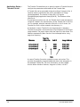
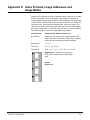
Film Mode — two film modes are supported: Simplex and Duplex.
Simplex – Each frame contains only one
image.
Duplex – A frame can contain one or two
images. Images are written alternately to
the A and B channels. The number of
images in any individual frame depends on
the index format and image level. If the
index format is single-level, each frame will
contain two images. If the index format is 2level or 3-level, the B channel will be left
blank in any frame where a higher-level
image follows the A channel image.
NOTE: With optical film capture devices, Duplex is associated with front
and back, since the fronts and backs of sheets of paper are
directly imaged to film. With the Writer, the concept of front and
back is not applicable since the input is electronic files, which do
not contain fronts and backs, but rather are identified as singlepage or multi-page.
For more information about film layout relative to film mode and input
file type, see Appendix A, Input Modes.
3-16
A-61056 March 2003
Film Leader Length — enter the desired length of the film leader (from
914 to 3048 millimeters/36 to 120 inches). The appropriate value is
determined by the requirements of the equipment that will be used for
subsequent retrieval of images. The default is 914 millimeters/36
inches.
Film Advance Length — enter the desired length of film to advance
between jobs (from 26 to 2515 millimeters/1 to 99 inches). The default
is 26 millimeters/1 inch.
InterDocument Gap — enter a value between 0.6 mm and 5.0 mm to
set the distance between images on film. The default is 0.7 mm. This
value will always be measured in millimeters regardless of the Film
Measurement Units.
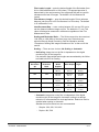
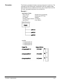
Scaling and Reduction Ratio — The Writer can archive documents at
1/20 (20X) to 1/99 (99X) of their hard copy size. Reductions are
achieved through image file scaling. See the illustration entitled,
“Examples of scaling and image orientation on film” at the end of this
section.
Scaling — There are two choices: No Scaling or Automatic.
• No Scaling: Image size on the film is dependent on the digital
resolution (dpi) of the image file.
The maximum page widths and lengths accommodated by the Writer
are listed below for No Scaling.
Image
Resolution
dpi
Effective
Reduction
Ratio
Maximum
Width
Simplex
Maximum Maximum
Width Duplex Length
100
77X
977 mm
38.5 in.
482 mm
19.0 in.
1740 mm
68.5 in.
200
39X
490 mm
19.3 in.
241 mm
9.5 in.
871 mm
34.3 in.
300
26X
325 mm
12.8 in.
160 mm
6.3 in.
579 mm
22.8 in.
400
19X
246 mm
9.7 in.
121 mm
4.8 in.
436 mm
17.2 in.
600
13X
162 mm
6.4 in.
78 mm
3.1 in.
289 mm
11.4 in.
• Automatic: image size on the film is independent of the digital
resolution (dpi) of the image file. Automatic scaling to a desired
reduction is recommended for most applications. Reduction Ratio is
enabled when scaling is Automatic.
Standard microfilm reductions are recommended:
- Simplex: 24X, 28X, 32X, 40X
- Duplex: 40X, 50X
A-61056 March 2003
3-17
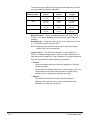
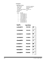
The maximum page widths and lengths accommodated by the Writer
are listed below for standard reductions.
Standard
Reduction Ratio
Maximum Width
Simplex
Maximum Width
Duplex
Maximum
Length
24X
302 mm
11.9 in.
149 mm
5.9 in.
538 mm
21.2 in.
32X
403 mm
15.9 in.
198 mm
7.8 in.
718 mm
28.3 in.
40X
490 mm
19.3 in.
241 mm
9.5 in.
871 mm
34.3 in.
50X
632 mm
24.9 in.
312 mm
12.3 in.
1125 mm
44.3 in.
Reduction Ratio — select a predefined option (24X, 40X, 50X) or
Custom. If you select Custom, the Scaling Factor option becomes
enabled.
Scaling Factor — enter the scaling factor as a number from 0 to 99
(i.e., 32 would be a 32X reduction ratio).
NOTE: Reducing more than 60X may produce undesirable image
quality and is not recommended.
Image Polarity — The Writer has the ability to write images in a
positive or negative image polarity. Positive is black characters on a
clear background. Negative is clear characters on a black background.
Retrieval considerations dictate polarity requirements.
• Positive
- Retrieval equipment does not need the capability of inverting
images for display.
- Lack of definitive borders may occur in some images on film. An
image border can be placed around positive images during
writing to film, to delineate the edges of the image.
• Negative
- The default in traditional microfilm retrieval equipment.
- Minimizes the impact of dust or other contamination when
displaying an image during retrieval.
3-18
A-61056 March 2003
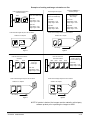
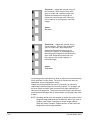
Examples of scaling and image orientation on film
Letter and legal size documents
scanned as follows:
S
c
a
n
n
e
r
Letter
E
G
Legal
200 dpi
Original resulting values
in the TIFF header tags:
Letter Size
Image Width = 1700
Image Length = 2200
Letter Size
Image Width = 1700
Image Length = 2200
Letter Size
Image Width = 2200
Image Length = 1700
Legal Size
Image Width = 1700
Image Length = 2800
Legal Size
Legal Size
Image Width = 1700
Image Length = 2800
Image Width = 2800
Image Length = 1700
These scanned images will print to film as follows:
Scaled to 24:1 Simplex
Scaled to 32:1 Simplex
E
G
E
Resulting values in the
TIFF header tags
after rotating:
Original resulting values
in the TIFF header tags:
These scanned images will print to film as follows:
Film Writing
G
Film Writing
Figure 1
Figure 2
Letter size documents scanned
as follows:
S
c
a
n
n
e
r
Letter
E1
Images are rotated by a
software package
Same images from Figure 1
Letter
E2
Letter size document
scanned as follows:
Resulting values
in the TIFF
header tags:
Letter Size
Image Width = 2200
Image Length = 1700
S
c
a
n
n
e
r
Letter
Letter
Letter
Letter
E2
E3
E4
E1
Rotated images
resulting values in
theTIFF header tags:
Letter Size
Image Width = 1700
Image Length = 2200
200 dpi
200 dpi
These scanned images will print to film as follows:
Film Writing
E4
E3
E2
E2
E1
Scaled to 40:1 Duplex
E1
Scaled to 24:1 Simplex
These scanned images will print to film as follows:
Film Writing
Figure 3
Figure 4
NOTE: If rotation is desired, the images must be rotated by a third-party
software product prior to passing the images to AWIS.
A-61056 March 2003
3-19
Film Templates — Image
Addressing tab
The Image Addressing tab contains parameters for controlling how
image addresses are created, and at what level each image will be
written to film. These values determine what will be accepted as a valid
starting image address for a new roll, in application setup.
See Appendix D, Index Format, Image Addresses and Image Marks for
detailed information.
Index Formats — a drop-down list of formats that can be used for the
images: No Indexing, Single Level, Two Level, and Three Level. This
value effects the hierarchal grouping of images on the film.
Field Width — the maximum number of characters needed in that
segment to accommodate the largest value that will be assigned during
the writing of images to film. For example, on a single-level roll with
10,000 images, the Level 1 field width must be at least 5. The total for
all enabled segments cannot exceed 12 but the maximum for each
individual segment is 9.
NOTE: Level 0 images are not assigned an image address.
An image address can have up to four segments depending on the
Index Format selected.
A field width must be specified for each enabled segment, except Fixed
which is optional. If you select Single Level index format, Level 1 field
width is enabled. If you select Two Level index format, Level 1 and
Level 2 are enabled. If you select Three Level index format, Level 1,
Level 2 and Level 3 are enabled.
Level Rule — the default level rule may be changed but it is not
recommended since they provide the most efficient and predictable
results. For more information about image levels, see Appendix D,
Index Formats, Image Addresses and Image Marks.
Set default — returns level rules to the original recommended settings.
3-20
A-61056 March 2003
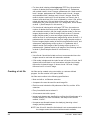
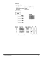
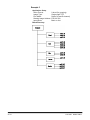
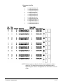
Film Templates — Frame
Annotation tab
The Frame Annotation tab contains parameters for optionally writing
the image address and reduction ratio on the frame in human-readable
characters placed between the image mark and the actual image.
Example 1: Simplex, 24X reduction with frame annotation enabled.
Example 2: Duplex; 24X reduction with frame annotation enabled.
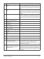
Following are descriptions of the fields on the Frame Annotation tab:
Enable Frame Annotation — allows you to write annotation
information on film.
Frame Annotation Position — not supported in Release 3.1.
Enable Image Border — when this option is enabled, a thin border will
be placed around all images. Placing a border around images helps
identify the boundaries on positive polarity images.
Frame Annotation Orientation — not supported in Release 3.1.
A-61056 March 2003
3-21
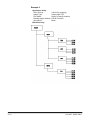
Film Templates — IMC
tab
The IMC tab controls the type of IMC (Image Management Code) that
will be written to the film preceding the images for every job that uses a
film template with IMC enabled.
IMC capability includes lead-end and preset coding, which provide
automatic setup parameters for the image retrieval device.
Enable IMC — provides a drop-down list that allows selection of IMC
as implemented for various Kodak optical film capture devices. This
facilitates integration of the Writer in environments where the retrieval
devices support current Kodak IMC. The options are: Disable IMC,
Enable IL70 code, Enable RIM2000 code, or Random Batch. The
default is Disable IMC.
Image Marks — not supported in Release 3.1.
Image Mark Author — determines the alignment of the image mark
relative to the image, and the physical dimensions of each image mark
size. Select either Kodak (default) or Other. Kodak image marks have
the leading edge of the image mark aligned with the leading edge of the
image.
Search Program — if IMC is enabled, a search program must be
specified. The search program tells the retrieval device which film
channel(s) (A and/or B) contain image marks, the image mark sizes
present on the film, and the image level represented by each image
mark size. This allows the retrieval device to locate and count the
image marks according to your needs. There are 31 search programs
available for use when writing images to film but the Writer does not
support creation of film for all of these. The drop-down box contains the
search programs that are supported by the Writer.
3-22
A-61056 March 2003
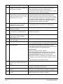
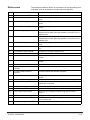
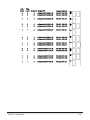
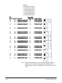
The table below provides information about the supported search
programs, to assist you in determining which program is appropriate
based upon the film to be written and the retrieval needs.
NOTE: The Search Program field drop-down box contains a value of
“1”, but the table does not. Search program 1 is used for
odometer-indexed film, which has special retrieval requirements
and does not contain image marks.
Index Format
Image Mark
Location
Image Mark
Sizes
How image marks will be counted
during retrieval
Single-level
Channel A
Small
2-level
Channel A
Small
Medium
Count small image marks as level 1
images, and medium image marks as
level 2 images.
10
3-level
Channel A
Small
Medium
Large
Count small image marks as level 1
images, and both medium and large
image marks as level 2 images.
12
3-level
Channel A
Small
Medium
Large
Count small image marks as level 1
images, medium image marks as level
2 images, and large image marks as
level 3 images.
18
Any
Channel A
Any/All
Count all image marks as level 1
images.
Count small image marks as level 1
images.
Search
Program
3
7
Splice Definition — specifies how film splices will be counted during
retrieval. The drop-down list provides these splice definitions: Ignore
Splices (default), Count splices as Level 1, Count splices as Level 2, or
Count splices as Level 3.
Duplex Front Channel — cannot be changed. The Writer supports
image mark creation in the A channel only.
Image Orientation — cannot be changed. For more information about
image orientation, see “Examples of scaling and image orientation on
film” earlier in this section.
A-61056 March 2003
3-23
Creating a film template
Film templates are created via AWIS Administration. To create a film
template follow the procedures below.
1. Select the AWIS Administration icon or Start>Programs>AWIS
Administration to start the AWIS Administration function.
2. Select File>Film Templates. The “Default” template appears in the
Template Name text box.
3. Click Create. The Create Template dialog box is displayed.
4. Enter the name of a new template and select an existing film
template that the new template will be based on and click OK. The
Film Template Server window is redisplayed with the new template
as the current template. All parameters from the “based on
template” are copied to the new film template.
5. Change any of the parameter values on the tabs as necessary.
6. Click OK to save the template and close the window or Save to
save the template and keep the window displayed.
3-24
A-61056 March 2003
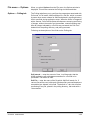
File menu — Options
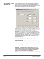
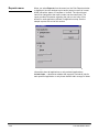
When you select Options from the File menu, the Options window is
displayed. This window contains the Polling and Advanced tabs.
Options — Polling tab
The Polling tab allows you to configure the parameters associated with
Poll mode. In Poll mode, AWIS searches for a Poll file, which is created
by some other means external to AWIS and placed in a polling directory
that is specified during application setup. When the Writer is integrated
with a scanner, Poll mode facilitates simultaneous scanning and filming
of images, without the need of an intermediate, manual batching step.
After all images indicated by a Poll file are processed, the Poll file is
deleted from the polling directory, and polling resumes.
Following are descriptions of the fields on the Polling tab:
Poll Interval — enter the amount of time, in milliseconds, that the
AWIS application will wait between searches for a Poll file to be
processed. The default is 3000.
Poll File — enter the name of the file which AWIS will search for. If
various files will be used, wild cards (Windows file system wildcards are
acceptable) are allowed in this field. The default is *.dat; this will allow
processing of any file, placed in the polling directory, that ends with a
.dat extension.
A-61056 March 2003
3-25
Pollfile — select the method by which the Poll file should be
processed.
• Check Contents for Path: a Poll file may be empty, or contain a full
pathname to either an input List file or batch directory. If the Poll file is
empty, the Poll file is processed the same as the Filename as PathIgnore Contents method, and must comply with the requirements of
that method. If the Poll file contains a full pathname, the specified List
file or batch directory is processed according to the application setup
and film template parameters.
• Filename as Path - Ignore Contents: an empty Poll file can be used
to specify an input batch directory. The Poll file name must be the
same as the batch directory name, and the Poll file must be placed in
the same home directory where the input batch directory is located.
• Contents is Listfile: a List file can be used as a Poll file. This
provides a method for automatically submitting List files which will
then be automatically processed. When processing is complete, the
List file is removed from the polling directory and copied to the same
directory as the Transfer file for the job.
Options — Advanced tab
The parameters on the Advanced tab are set to optimize performance.
During installation the values of these parameters are set to the default.
For most applications, the defaults are sufficient and should only be
changed to address a specific issue and after a thorough review of the
following information.
Following is a description of the fields on the Advanced tab:
Number of Commands — The maximum number of print commands
that can be active simultaneously. The maximum value depends on the
Number of Files value since the product of the Number of Files and
Number of Commands, cannot exceed 120. Default 8.
3-26
A-61056 March 2003
Number of Files — The maximum number of image files that a print
command can contain. The maximum value depends on the Number of
Commands value. The product of the Number of Files and Number of
Commands cannot exceed 120. Default 8.
The Number of Commands and Number of Files work together to
maximize command and image throughput by minimizing the amount of
time the Writer will have to wait for print commands. This is
accomplished by ensuring that there are at least two commands active
at once: the command currently being processed by the Writer, and the
command on the Writer disk waiting to be processed. For AWIS, this
results in four active commands:
• one command being built and copied to the Writer
• one response received from the Writer when a command is
completed
• the two commands on the Writer (one waiting to be processed and
one being processed)
This implies that the minimum value for Number of Commands is 4.
This value is usually left at the default value of 8, which allows a few
extra commands available if needed.
Image file size and Writer disk size must be considered when
determining the appropriate value to enter for the Number of Files. To
determine this value, use the following formula as a guideline:
For example:
File Retry Count — The number of times AWIS attempts to copy an
image file to the Writer before giving up and signaling an error. This
value is used in conjunction with the Retry Delay value to determine the
total amount of time AWIS will wait for the Writer to process existing
commands and image files and make space available on its disk.
Default: 20.
Retry Delay — The amount of time (in milliseconds) to wait before
attempting to copy an image file to the Writer again. This value is used
in conjunction with the File Retry Count value to determine the total
amount of time AWIS will wait for the Writer to process existing
commands and image files and make space available on its disk.
Default: 2000.
A-61056 March 2003
3-27
The combination of the default Retry Delay (2000 milliseconds) and
default File Retry Count (20 attempts) gives the Writer 40 seconds to
finish processing commands and image files and make space for new
commands and files. For most applications this is sufficient; however,
when processing very large image files (greater than 750K), 40
seconds may not be enough. In this case, the File Retry Count needs to
be increased. Increase the value in increments of 5 until the largest file
can be processed without a 3034 error occurring. It is important not to
set this to some arbitrarily large value, because in the event of an error,
this can increase the time it takes to report the error. Setting File Retry
Count to a value too small causes the 3034 error to occur more
frequently.
Generally, the Retry Delay should be kept at the default. Decreasing
this value causes the copy requests to become more frequent but also
increases network traffic. Increasing this value may cause a loss of
throughput.
The product of Retry Delay and File Retry Count must be a time interval
larger than the time it takes to process the largest image file.
Transaction Timeout —The maximum time (in seconds) AWIS will
wait for the Writer to process a command and send a response.
Default: 180. This value may only need to be changed when the
processing of a print command and its associated images takes longer
than 90 seconds.
The value of this parameter should always be about 30 seconds larger
than the time specified by the Retry Delay and File Retry Count
parameters.
NOTE: If network performance seems to be an issue, the following
values may optimize performance: 4, 4, 40, 2000, 300
respectively.
File menu — Exit
3-28
Select File>Exit to close AWIS Administration.
A-61056 March 2003
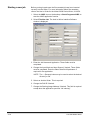
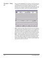
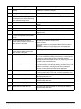
Purge menu
When you select Purge from the menu bar, the Purge Job window is
displayed. Use this window to remove any or all of the following from
the system: job data, input List files, Transfer files, and image files.
NOTE: Only verified jobs and their associated files can be deleted using
the Purge function. See Chapter 4, “File Menu — Verify Jobs”
for more information.
Jobs — displays information about the jobs that have been verified,
including the job name, the application used to run the job, the date and
time that the job was started, the fact that the job was verified, the login
ID of the operator who verified the job, the workstation ID of the host
PC from which the job was run, the Roll ID assigned to the film when
the job was run, and a status code of 4 (the code for “verified”).
Rolls — displays information for the roll of film associated with the
selected job, including the Roll ID assigned to the film when the job was
run, the total number of images written to film using that job, the first
and last image addresses assigned using that job, the date and time
that the job was completed, and the roll number indicating whether the
job required more than one roll of film.
NOTE: The columns and rows on the Purge Job window can be resized
by positioning the mouse on the column or row lines in the
headings and moving the mouse, while holding down the left
mouse button, to the desired position.
A-61056 March 2003
3-29
Purging jobs and /or
associated files from the
system
To remove job data and/or associated files from the system:
1. Select the AWIS Administration icon or Start>Programs>AWIS
Administration to start the AWIS Administration function.
2. Select Purge from the main menu. This will be available only if there
are jobs with a status of Verified in the system.
3. Select the desired job from the Jobs table.
NOTE: Even though multiple jobs can be selected at one time, the
system will only perform actions on the first job selected.
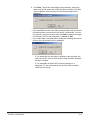
4. Click Purge. The Purge Job [jobname] window is displayed.
5. Select one or more of the following options:
- Delete Job Records from AWIS Database: allows the Roll ID
associated with the job to be re-used, if necessary, by the
application used to run the job. All data pertaining to the selected
job will be deleted from the awis.mdb database and the job will be
removed from the Jobs table in the Purge Job window. If this
option is used alone, the capability to use this purge function, to
remove associated files for the job from the system, will be lost.
- Delete Input Source List File(s): this option is enabled only if a
List file was used to submit images for the job, and the file was
not previously deleted using this purge option. This option may be
used alone to delete just the input List file and not remove the job
from the Jobs table.
- Delete Index Data File: this option is enabled only if a customer
Transfer file was generated using an index data file. This option
may be used alone to delete just the index data file and not
remove the job from the Jobs table.
- Delete Transfer File: this option is enabled only if a Transfer file
was created. This option may be used alone to delete just the
Transfer file and not remove the job from the Jobs table.
3-30
A-61056 March 2003
- Target Directory Path: this option is enabled and a value must
be specified only if the Delete Job Records option is selected and
the Delete Transfer file option is enabled but not selected. This
option provides the capability to move the Transfer file rather than
delete it. This field must contain a valid path to a directory where
the Transfer file will be moved. The ... button can be used to open
the Directory Selection dialog box and navigate to the desired
directory, or a path can be typed directly into the Target Directory
Path field.
- Delete Input Source Image Files — this option can be used to
delete the source image files when a List file was used to submit
images for the job, and the List file is still on the system. The
accompanying fields are informational only.
A-61056 March 2003
3-31
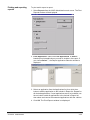
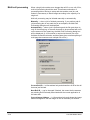
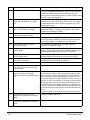
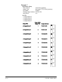
Reports menu
When you select Reports from the menu bar, the Print Reports window
is displayed. Use this window to print and/or export a report of current
AWIS jobs with a status of Complete or Verified. The report format
cannot be changed but the report content can be customized. The
report provides information regarding the jobs run and rolls of film
written for each application defined via application setup. See the
sample report at the end of this section.
From Application — determines whether the report includes
information about all applications or only selected applications.
Include Jobs — determines whether the report will include all jobs for
each specified application or only those that fall within a range of dates.
3-32
A-61056 March 2003
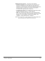
Printing and exporting
reports
To print and/or export a report:
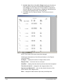
1. Select Reports from the AWIS Administration main menu. The Print
Reports window will be displayed.
2. From Application: Select either All Applications or Select…
based upon what applications you want to include in the report. If
you choose Select…, the Report Application Selection window is
displayed.
3. Select an application from the Applications list, then click the >
button to add the application to the Include in Report list. Repeat for
all desired applications. If most applications are to be included, use
the >> button to add all applications to the Include in Report list,
then select and remove the unwanted applications with the < button.
4. Click OK. The Print Reports window is redisplayed.
A-61056 March 2003
3-33
5. Include Jobs: Select either All or Range based upon the jobs you
want included in the report for each selected application. If you
select Range, the From Date and To Date fields are enabled and
must be specified. A small calendar is displayed, which allows you
to easily select the desired day, month and year.
6. Click OK in the Print Reports window. The Preview window is
displayed:
.
NOTE: The format of the report cannot be changed.
Following are descriptions of the fields and buttons on the Reports
Preview window:
# Images — displays the number of images written to film.
Elapsed Time — the time it took to run the job.
Start/End — displays the dates that the job was started and completed.
First I/A and Last I/A — assigned to the images written to film.
Operator and Machine ID — who ran the job and the name of the
Writer used to write images to film.
Date — displays the date that the report was printed/exported.
3-34
A-61056 March 2003
Buttons
Goes to the first page.
Goes to the previous page.
Goes to the next page.
Goes to the last page.
Cancels an action.
Help menu
Zoom/reduce the screen
display (toggle)
Opens the Print dialog box for
the default printer for the PC
you are working on.
NOTE: The printer cannot be
changed.
Opens the Export dialog box.
Destination can be “Disk file” or
“Mail via MAPI”. Disk file is the
default.
Opens the Export dialog box.
Destination can be “Disk file” or
“Mail via MAPI”. Mail via MAPI
is the default.
Closes this window.
The Help menu contains three options:
This window — opens the Help dialog box to display the on-line help
page that applies to the currently active window.
Contents and Index — opens the Help dialog box to display the first
page of the on-line help with Contents and Index tabs.
About — displays a window containing software copyright and version
information.
A-61056 March 2003
3-35
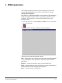
4 AWIS Application
This chapter provides an overview of the windows you can access
when using AWIS Application, as well as procedures for opening,
verifying and running jobs.
See Chapter 3, AWIS Administration for an overview of the windows in
AWIS Administration and procedures for setting up applications, film
templates, defining a Writer, removing jobs from the system and
printing a report.
• From the Start menu, select Programs > AWIS or click on the AWIS
icon on the desktop.
The Archive Writer Interface Software window is displayed.
The menu bar provides the following options:
File — allows you to set up and run a new job, open an existing job that
is not yet complete, verify a job that is complete and exit the AWIS
application.
Reports — allows you to print a report of current AWIS jobs.
Setup — when setting up a new job, allows you to view the parameters
associated with the selected Writer and application.
Help — provides access to AWIS help.
A-61056 March 2003
4-1
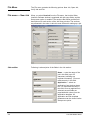
File Menu
The File menu contains the following options: New Job, Open Job,
Verify Job and Exit.
File menu — New Job
When you select New Job from the File menu, the Archive Writer
Interface Software window is populated with job setup fields, and the
Setup menu option is enabled. The sections that follow provide field
descriptions for each section of the Job Setup window. The sections
are presented in the order in which is most efficient for setting up a job.
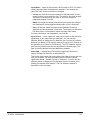
Job section
Following is a description of the fields in the Job section:
Name — enter the name of the
job in this field (up to 25
characters including any
keyboard character). You must
make an entry in this field.
Application — select an
application from the drop-down
list. You must make an entry in
this field. Once an application is
selected, several fields are
populated with values from the
application template. All
application and film template
parameters can be viewed via the
Setup menu option.
4-2
A-61056 March 2003
Input Mode — select an input mode: List file, Batch or Poll. This field is
initially populated from the application template. If you change this
value, the Input Source must also be changed.
• List file: an ASCII text file that contains the full pathnames to each
image file that is to be written to film. The order in which the images
are written is determined by the order in which the image file
pathnames appear in the file.
• Batch: the image files within each directory are sorted according to
the Windows file sorting algorithm and written to film in that order.
• Poll: poll files are sorted according to the Windows file sorting
algorithm and are processed in that order. The directory is where the
Poll files reside, not necessarily where the image files reside.
For more information, see Appendix A, Input Modes.
Input Source — enter a path to a valid List file, Batch or Poll directory
(depending on the input mode you selected). You can use the ...
(Browse) button to display the File Selection (for List files) or Directory
Selection (for Batch or Poll modes) windows to assist you in location of
the desired List file, Batch or Poll directory. The File Selection window
and Directory Selection window are described on the next page. This
field is initially populated from the application template.
Index Data — enabled only if the selected application specifies a
custom Transfer file that uses an index data file.
This field is used to pass the name of the Index Data file to the user exit
on a per-job-basis. For more information see the section entitled,
“Application Setup - Transfer File tab” in Chapter 3. You can use the ...
(Browse) button to display the File Selection window to assist you in
locating the desired index data file. The File Selection window is
described on the next page.
A-61056 March 2003
4-3
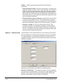
File Selection Window
Drive — select the drive where the desired file is located.
Directory Name — select the directory in which to find the file name.
Once selected, a list of files appears in the File Name list box.
File Name — select the file name from the list box. Once selected, the
file name appears in the File Name text box.
OK — click to accept the List file and close the File Selection window.
Cancel — to ignore your selection and close the File Selection window.
To select a file:
1. Select the Drive.
2. Select the Directory Name.
3. Select the File name.
4. Click OK.
4-4
A-61056 March 2003
Directory Selection Window
Drive — select the drive where the desired directory is located.
Directory Name — select the directory where the image or Poll file(s)
reside. Once selected, any image or poll files within the directory are
displayed in the File Name list box. If the input mode is batch, and the
image files are in a subdirectory(ies), the File Name list box will remain
empty.
OK — click to accept the Batch or Poll directory and close the Directory
Selection window.
Cancel — to ignore your selection and close the Directory Selection
window.
To select a directory:
1. Select the Drive.
2. Select the Directory Name.
3. Click OK.
A-61056 March 2003
4-5
Archive Writer section
When a Writer is selected, the system connects to the Writer. Once
connected, the following options are enabled: Advance Film, Writer
Status buttons; the Archive Writer Parameters selection under the
Setup menu and the Show More button in the Film section.
The Writer returns status information
related to the film cassettes and this
status is displayed in the Upper and
Lower Cassette graphics in the Film
section.
Archive Writer —select an available
Writer from the drop-down list. You
must make an entry in this field. Only
Writers currently defined on the
system are displayed. If a selected
Writer is being used by another
process, or is not powered up and
initialized, an informational message is displayed and you must select a
different Writer.
Advance Film — opens the Advance Film dialog box, which is
populated with the value specified via film template setup. This value
can be changed if desired.
Writer Status — updates the information in the Film section graphics.
Run To End — enabled only after a job has been run. Displays the Run
to End dialog box that provides the options to perform end-of-roll
processing (writing of trailer page to film) and/or physically running the
film completely on to the takeup spool. End-of-roll processing may not
be enabled, depending on preceding actions.
4-6
A-61056 March 2003
Film section
Following is a description of the fields in the Film section:
Roll ID — this field is populated with
a value after an application is
selected in the Job section. The
value is the next available number
for that application based upon
current records in the awis.mdb. This
value can be changed if desired,
using any number (up to 8 digits) that
does not already exist in the
awis.mdb for that application. This
field must contain a value
Upper Cassette — displays the
amount of film remaining in the upper
cassette. This field is enabled upon
successful connection to the
selected Writer. This is informational
only and cannot be changed.
Lower Cassette — displays the
amount of film remaining in the lower
cassette. This field is enabled upon
successful connection to the
selected Writer. This is informational
only and cannot be changed.
Show More — when selected, the
Additional Film Status window is displayed (shown next). This is
informational only and cannot be changed.
Additional Film Status Window
Last Image Mark Written (Upper and Lower Cassette) — displays
the level of the last image mark written. If a cassette is not present in
the Writer, the value will be 0.
Last Image Address Written (Upper and Lower Cassette) —
displays the image address assigned to the last image that was written
to the roll of film in that cassette. If a cassette is not present in the
Writer, the value will be 0000.00.000.001.
A-61056 March 2003
4-7
Images section
The following fields are updated interactively as a job runs:
% Complete — displays the
percentage of the total for the images
already processed.
Processed Count — displays the
number of images already processed.
Total to Process — displays the
number of images to process.
Starting Image Address — this field
is populated with the value from the
application template when an
application is selected in the Job
section. This value can be changed if
desired, but the value must comply
with the parameters specified in the
film template. For more information, see the section entitled, “Film
Templates - Image Addressing tab” in Chapter 3. As a job runs, this
field changes to show the “Last Image Address” that was assigned.
Starting Image File — this field is empty until a job is started. As a job
runs, this field changes to show the “Last Image File” that was
processed. Long file names will be truncated and cannot be viewed
since the full pathname is displayed.
Buttons
Start — becomes enabled when a job name, application and Archive
Writer have been specified. When you choose Start, processing takes
place depending on the setting for Input mode.
• If Input mode is either batch or List file, processing of the image files
begins.
• If Input mode is Poll, polling for Poll files begins.
Job progress is reported in the Images section.
Stop — becomes enabled when Start is selected. If you select Stop in
the middle of processing, AWIS completes the processing of the
current command transaction; the Images section will indicate where
processing stopped.
In addition, if the Input mode is Poll, the following message is
displayed:
4-8
A-61056 March 2003
• If you select Stop Filming, AWIS completes the processing of the
current command transaction, then stops; the Images section will
indicate where processing stopped.
• If you select Stop Polling, AWIS completes the job before stopping.
Cancel — cancels the New Job function and clears the Archive Writer
Interface Software window.
Exit — exits the AWIS application.
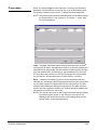
Status bar
A-61056 March 2003
The bottom of the display is dedicated to the reporting of general status
associated with the AWIS application. Typical items reported include,
Ready, Writing Images and Polling Input Directory. In addition, at the
end of a job, the total count of images written to film (actual pages) will
be displayed.
4-9
Starting a new job
Before you begin make sure the film cassette(s) have been inserted
correctly into the Writer. For more information about film cassettes,
refer to the User’s Guide for the Kodak i9600 Series Writer, A-61058.
1. Select the AWIS icon on the desktop or Start>Programs>AWIS to
start the AWIS application function.
2. Select File>New Job. The Archive Writer Interface Software
window is displayed.
3. Enter the Job Name and Application. These fields must be
completed.
4. Change the Input Mode and Input Source if desired. These fields
must be completed. Enter the Index Data file full pathname if
required for the application.
NOTE: The ... (Browse) buttons may be used to select the desired
directory or file.
5. Select an Archive Writer. This is required.
6. Change the Roll ID if desired.
7. Change the Starting Image Address if desired. This field is required
except when the application specifies “No indexing”.
4-10
A-61056 March 2003
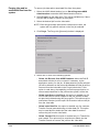
8. Click Start. The job will immediately start processing, unless the
input mode is Poll mode, then AWIS will begin looking for Poll files.
Upon completion of processing, the following message will be
displayed:
• If you select No , the New Job fields remain populated with current job
information and the connection to the Writer is maintained. You can
now specify a new input source and select Start to add more images
to the same roll ID for that application, or Cancel or Exit.
• If you select Yes, a message will be displayed indicating that the roll
is done, then the following will be displayed:
- If you select Yes, the job status is updated in the awis.mdb, the
New Job function exits and the Archive Writer Interface Software
window is cleared.
- If you select No, the Multi-Roll Processing dialog box is
displayed. For more information see the next section entitled,
“Multi-roll processing”.
A-61056 March 2003
4-11
Multi-roll processing
When a single job contains more images than will fit on one roll of film,
multi-roll processing should be used. This allows continuation of
processing without having to setup and start another new job, and
makes it unnecessary to batch images according to the capacity of a
single roll.
Multi-roll processing may be initiated manually or automatically.
Manually — when a job is finished processing, if you perform end-ofroll processing but do not mark the job as complete, the Multi-Roll
Processing dialog box will be displayed.
Automatically — when a job is processing and the film gets down to
only 10 feet remaining, or the next document to be processed will not fit
on the amount of film remaining, the Multi-Roll Processing dialog box
will be displayed. (A 10-foot trailer is required at the end of a roll to
facilitate successful retrievals, and the system does not allow splitting of
multi-page documents across multiple rolls of film.)
Current Roll ID — is informational only and shows the roll ID for the roll
that was just finished.
Next Roll ID — can be changed if desired, but cannot be the same as
any existing Roll ID already associated with the current application in
the awis.mdb.
Current Image Address — is informational only and shows the image
address assigned to the last image on the roll that was just finished.
4-12
A-61056 March 2003
Starting IA for the next roll — can be one of the following:
• Use next in sequence: the IA assignment will continue from the
previous roll, based upon the film mode and image addressing
parameters in the film template, and the level of the first image. In the
previous example, the starting IA could be FF.006.000.000 or
FF.005.002.000, depending on the image level.
• Use Application default: the IA assignment will start with the value
specified in application setup, e.g., FF.001.000.000.
• Other: the IA assignment will start with the value specified in this
field. The value must comply with the parameters specified in the film
template. For more information, see the section entitled, “Film
Templates - Image Addressing tab” in Chapter 3.
NOTE: The Transfer file for each subsequent roll will be created in the
same directory as the Transfer file for the first roll.
A-61056 March 2003
4-13
File menu — Open
Job
When you select Open Job from the File menu, the Open Job window is
displayed with information about the currently defined jobs that are not
complete. Use this window to perform additional actions on these
pending jobs.
NOTE: The columns and rows on the Open Job window can be resized
by positioning the mouse on the column or row lines in the
headings and moving the mouse, while holding down the left
mouse button, to the desired position.
The window displays the following fields for each job:
Job Name: the name as entered by the operator when the job was
created.
Status: status of that job. The following status can be displayed:
• Need Input — indicates that all images for the job were written to film
but the job has not been marked as complete. Additional images can
be added to the roll if desired.
• Write Images — indicates that all images for the job were not written
to film due to some interruption of processing. The job can be
restarted and resumed where it was interrupted. A job is not available
to be marked as complete until all images are written.
Roll ID — the Roll ID assigned to the film when the job was run.
Application — the application used to run the job.
Started — date and time when this job was first started.
Workstation ID — name of the host PC from which the job was run.
Status Code and Operation Code — used internally by the system.
First Roll — used internally by the system.
4-14
A-61056 March 2003
Buttons
OK — opens a selected job. If any information needed to open the job
is not available (e.g., the application template was deleted), an
appropriate error message will be displayed.
Complete — updates the job status to complete and removes the job
from the Open Job table. This is only enabled for those jobs whose
status is “Need Input”.
New — displays the Archive Writer Interface Software window
populated with empty New Job fields. For more information see the
section entitled, “File Menu - New Job” in this chapter.
Delete — deletes a selected job from the Open Job table but unlike
Purge in AWIS Administration, does not remove all job history from the
database; transaction information is retained.
Cancel — closes the Open Job window and returns to the main AWIS
window.
Opening a job
You can open a job in one of the following ways:
• Position the arrow on the line of the desired job name and click OK.
• Single-click on any line and click OK.
• Double-click on any line.
The Archive Writer Interface Software window is displayed, populated
with the same fields used when starting a new job. The fields contain
the values used when the job was run previously. The job status
determines which fields contain values. For more information about
using these fields see the section entitled, “File menu - New Job” in this
chapter.
NOTE: You can only work with one job at a time, even though you can
select more than one job.
A-61056 March 2003
4-15
File menu — Verify
job
When you select Verify Job from the File menu, the Verify Job window
is displayed. You can only verify one job at a time. This feature can be
used to facilitate job and roll tracking for quality control and audit
purposes. Once a roll is successfully verified for image quality, etc., the
job status can be changed to indicate that, and the job information can
be purged from the system, if desired, using AWIS Administration.
Jobs — displays information about the jobs that have been completed,
including the job name, the application used to run the job, the date and
time that the job was started, the fact that the job was completed, the
Login ID of the operator who completed the job, the workstation ID of
the host PC from which the job was run, the Roll ID assigned to the film
when the job was run, and a status code of 2 (the code for Complete).
Rolls — displays information for the roll of film associated with the
selected job, including the Roll ID assigned to the film when the job was
run, the total number of images written to film using that job, the first
and last image addresses assigned using that job, the date and time
that the job was completed, and the roll number indicating whether the
job required more than one roll of film.
4-16
A-61056 March 2003
Buttons
Resubmit — job status is changed to Write Images and the job is
removed from the Jobs table here. The job can be accessed via
File>Open and the images can be written to film again using the
original job setup. This is useful when the finished film does not meet
quality control requirements.
Complete — if a job in the table has been changed to Verified, it can be
reset to Complete using this button.
Verify — job status is changed to Verified in this table.
OK — saves status changes made to any jobs via Complete and Verify
and closes the Verify Job window.
File — Exit
Select File>Exit to close the AWIS Application.
Reports menu
The Reports menu allows you to print and/or export a report. See
Chapter 3, AWIS Administration for information on printing and/or
exporting reports.
Setup menu
Enabled only when setting up and running jobs, after a Writer or
application has been selected. From this menu you can view the
parameters associated with the Writer and the application setup.
A-61056 March 2003
4-17
5
Troubleshooting
When checking AWIS.LOG for errors, scroll to the first error with the
same time stamp as the last error. This begins the error and reporting
sequence for the current error.
NOTE: We do not recommend using the diagnostic error logging level;
this is intended for use by Kodak Service.
Errors numbered 1000 through 9999 in AWIS.LOG are AWIS errors. If
the error was caused by an error on the Writer itself, an error numbered
100 through 999 may follow the AWIS error(s) in the log.
Writer errors 103 through 229 are recoverable by rebooting the Writer.
If any of the other Writer errors are not recoverable by rebooting the
Writer, call the Kodak Customer Response Center or your integrator.
Generally, 100-series errors are warnings/informational messages,
200-series errors are warnings/correctable situations, 300-series errors
are development debug tools (should not show up in the field), 700series are critical imaging chain errors, 900-series are other critical
system errors.
Setup problems
If you are having problems with the Writer, follow the instructions for the
applicable category below.
Cannot connect to the Writer
1. Boot the Writer.
2. If you cannot connect to the Writer from AWIS, reboot the Writer
and then reboot the workstation that AWIS is running on.
3. If you still cannot connect to the Writer, contact the System
Administrator.
Bad Image
If a bad image is detected during writing of images to film, a dialog box
provides the name of the bad file. It is up to the user to replace this file
with any good TIFF file (you may use a blank TIFF). The bad file must
be replaced, it CANNOT be deleted.
NOTE: Running the input files through the TIFFCHKR application first
will help to identify non-compliant files prior to processing. For
more information see Appendix B.
Check Image Address
If the operator receives IA format errors, the starting image address for
all jobs needs to be verified before the job is started.
A-61056 March 2003
5-1
AWIS error log
The chart below defines AWIS error numbers, the corresponding
messages, and an explanation of what each error signifies. In certain
cases, corrective actions are provided.
Key:%s Actual message contains character designator or file name(s).
%d Actual message contains numeric value.
Code
Message
Description
0
Success
This is the normal return status for all operations. The error log
will not usually contain any of these messages.
1000
Error opening file:%s.
The specified file cannot be opened. This usually happens when
the file does exist, and may be caused by abnormal operation of
the Writer (such as powering the Writer down or setting it to
offline while image writing is in process). This may also be
caused by manually deleting files AWIS expects to find, such as
the index data file and template files.
1002
Error reading file:%s.
The specified file cannot be read. This can be caused by the file
not existing, by other programs having the file locked, or by a
corrupted file. This can also be caused by low memory
conditions, where there is not enough memory to allocate a
buffer for reading the file contents.
1004
No index data file specified
The application did not provide the name of an index data file.
This is an informational message only.
1007
Failed to write to file%s.
The file was successfully created, but a failure occurred in
writing to the file. This may be caused by disk failures or running
out of disk space. If the file is being written to the Writer drive,
this error may be caused by the Writer being shut down or by an
error occurring in the Writer that removes or corrupts the remote
drive connected to the Writer.
1008
Failed to rename file%s to%s.
An attempt to rename a file has failed. This may be caused by
the destination file already existing, or by a failure of the disk the
file resides on.
1009
Cannot write file%s: no data to write to An internal program error has caused an attempt to write a zeroit...
length data buffer to the file. This error should never occur.
1010
Error creating file%s.
Failed to create the specified file. This may occur if the disk the
file is to be created on is corrupted, missing, or out of space.
1011
Error closing file%s.
Failed to close the specified file. This may occur if the disk is
corrupted.
1012
Error code%d returned during attempt
to create file%s.
Failed to create the specified file. This may occur if the disk the
file is to be created on is corrupted, missing, or out of space. The
error code is documented in the Microsoft Visual C++
documentation. Refer to the section on error codes returned
from the file IO functions.
5-2
A-61056 March 2003
Code
Message
Description
1013
Error code%d returned during attempt
to read file%s.
Failed to read the specified file. This may occur if the disk the file
is on is corrupted or missing. The error code is documented in
the Microsoft Visual C++ documentation. Refer to the section on
error codes returned from the file IO functions.
1014
Error code%d returned during attempt
to write to file%s.
Failed to write to the specified file. This may occur if the disk the
file is on is corrupted or missing. The error code is documented
in the Microsoft Visual C++ documentation. Refer to the section
on error codes returned from the file IO functions.
1016
Error during attempt to create
directory%s.
Failed to create temporary directory to place single-page TIFF
files from multi-page TIFF files.
1017
Couldn’t send an input file specification Socket error.
to the Writer for file%s.
1018
Couldn’t send an output file
specification to the Writer for file%s.
Socket error.
1019
Couldn’t get an input file specification
acknowledgment from the Writer for
file%s.
Socket error.
1020
An input file specification contained an
invalid filename:%s.
Socket error.
1021
An input file specification
Socket error.
acknowledgment contained and invalid
value:%c.
1022
And input file specification
acknowledgment contained an invalid
value:%c.
1023
Couldn’t get a file content acknowledge Socket error.
from the Writer for file%s.
1024
Failure writing contents of%s to Writer. Socket error.
1025
Couldn’t send the file content
acknowledgment to the Writer for
file%s.
Socket error.
1026
Couldn’t write file%s to the Writer.
Socket error.
1027
Couldn’t read file%s from the Writer.
Socket error.
1028
Couldn’t get an output file specification Socket error.
acknowledgment from the Writer for
file%s.
2000
File open error
2010
Socket Error%d
2012
Socket Error%d. Host sockets have
been reset.
2013
Socket Error%d. No socket data found. Port and protocol information could not be found. The Services
Check Services file.
file may not have entries for the socket connections.
2014
Socket Error%d. Host not found. Check The Writer name could not be found either in the host file or on
Writer name.
the network.
2016
Can’t find winsock.dll.
A-61056 March 2003
Socket error.
Could not open file.
The Writer has reset the socket connection.
The winsock.dll is not on the system.
5-3
Code
Message
Description
3000
Error writing command%s.
Failed to create a command file containing the specified
command. This may be caused by the Writer being offline or
inoperable. This problem can be corrected by making sure the
Writer is online and the Writer disk is available. It may be
necessary to reboot the Writer and to make sure the NFS
connection to the Writer is working properly.
3001
Error sending command.
Failed to create a command file containing the specified
command. This may be caused by the Writer being offline or
inoperable. This problem can be corrected by making sure the
Writer is online and the Writer disk is available. It may be
necessary to reboot the Writer and to make sure the NFS
connection to the Writer is working properly.
3002
Error creating semaphore.
Failed to create a semaphore file. This may be caused by the
Writer being offline or inoperable. This problem can be corrected
by making sure the Writer is online and the Writer disk is
available. It may be necessary to reboot the Writer and to make
sure the NFS connection to the Writer is working properly.
3004
Error in Astring parse.
An internal programming error has occurred in the AWOL
parsing routine. This error should never occur.
3005
Response file for command %d, no
response value in file.
An empty Response file has been created by the Writer. This
may be due to an internal fault in the Writer. This problem may
be corrected by closing the application and restarting the Writer.
3009
Error parsing response parameter
number.
An internal programming error has occurred in the AWOL
parsing routine in attempting to parse the response parameter
number from the string. This error should never occur.
3010
Error parsing Archive Writer error
number.
An internal programming error has occurred in the AWOL
parsing routine in attempting to parse the error number from the
response file. This error should never occur.
3012
Parameter number out of range.
The parameter number contained in the response file is not
valid. This error should never occur.
3013
Image buffer full.
The internal image buffer is full. This is normal operation. This
error should never appear in the error log file.
3014
Invalid Writer drive.
The application has supplied a drive letter that is invalid. Make
sure the specified drive letter is correct.
3016
Command timed out. Command: %s.
The Writer has not responded to the command within the
allowed period of time (usually 90 seconds). Check that the
Writer is online and that the drive assigned to the Writer is
available. It may be necessary to restart the Writer.
3018
No more files.
This is a normal internal status indicating that no more files are
available for processing.
3021
File mismatch.
The response file returned by the Writer contains the wrong file
Expected: %s, got: %s, original file: %s. specification. This error indicates a communication or other
internal failure in the Writer and may be corrected by closing the
application and restarting the Writer.
3022
No image address in %s (Image log
file).
5-4
The image log file returned by the Writer does not contain a valid
image address where one was expected in the file. This error
indicates a communication or operational failure in the Writer
and may be corrected by closing the application and restarting
the Writer.
A-61056 March 2003
Code
Message
Description
3023
Can't open transfer file.
The transfer file cannot be opened. This may be caused by a
corrupted hard disk or by an invalid path specified for the
location of the transfer files.
3027
Rollname too long.
More than 8 characters have been specified for the roll name.
3031
Command buffer empty.
An internal programming error in the AWOL DLL has occurred.
3032
No more disk space.
There is not enough disk space on the Writer drive to create a
file. This error should never appear in the error log.
3033
Can't overwrite command.
This is an internal program status and will never appear in the
error log file.
3034
Failed to copy file to Writer.
A file cannot be copied to the Writer. This is caused by a failure
of the communication link with the Writer or by an internal failure
in the Writer. Correct this by closing the application and
restarting the Writer.
3036
Could not find response file, %s.
A request has been made for information from the Writer, the
Writer has executed the command, but no response file was
returned. This is caused by a failure of the communication link
with the Writer or by an internal failure in the Writer. Correct this
by closing the application and restarting the Writer.
3037
Error creating the film leader.
An error was returned from the Writer in attempting to create a
film leader. This may be caused by a failure of the film cassette,
by not having enough film in the cassette, or by an internal error
in the Writer. Correct this problem by making sure the film
cassette contains enough film and that the Writer
communication link is working properly.
3038
Error in image address on cassette.
The film cassette contains an invalid image address.
3040
Error sending IMC command.
The IMC command could not be successfully sent to the Writer.
This is caused by a failure of the communication link with the
Writer or by an internal failure in the Writer. Correct this by
closing the application and restarting the Writer.
3041
Error sending Image Frame command. The command to set the next image frame could not be
successfully sent to the Writer. This can be caused by a failure
of the communication link with the Writer or by an internal failure
in the Writer. Correct this by closing the application and
restarting the Writer.
3043
Error sending System command to
Writer.
The System command could not be successfully sent to the
Writer. This is caused by a failure of the communication link with
the Writer or by an internal failure in the Writer. Correct this by
closing the application and restarting the Writer.
3044
Error sending command to get
remaining film.
The command to get the remaining film could not be
successfully sent to the Writer. This is caused by a failure of the
communication link with the Writer or by an internal failure in the
Writer. Correct this by closing the application and restarting the
Writer.
A-61056 March 2003
5-5
Code
Message
Description
3045
Error sending command to get the film
status.
The command to get the film status could not be successfully
sent to the Writer. This is caused by a failure of the
communication link with the Writer or by an internal failure in the
Writer. Correct this by closing the application and restarting the
Writer.
3046
Error sending command to get the film
cassette data.
The command to get the cassette data could not be successfully
sent to the Writer. This is caused by a failure of the
communication link with the Writer or by an internal failure in the
Writer. Correct this by closing the application and restarting the
Writer.
3047
Error sending command to set the
diagnostic port.
The command to set the diagnostic port could not be
successfully sent to the Writer. This is caused by a failure of the
communication link with the Writer or by an internal failure in the
Writer. Correct this by closing the application and restarting the
Writer.
3048
Error sending command to set the
status monitor port.
The command to set the status monitor port could not be
successfully sent to the Writer. This is caused by a failure of the
communication link with the Writer or by an internal failure in the
Writer. Correct this by closing the application and restarting the
Writer.
3049
Error sending command to set the
image writing parameters.
The command to set the image writing parameters could not be
successfully sent to the Writer. This is caused by a failure of the
communication link with the Writer or by an internal failure in the
Writer. Correct this by closing the application and restarting the
Writer.
3051
Error sending command to set the date The command to set the internal date and time could not be
and time in the Writer.
successfully sent to the Writer. This is caused by a failure of the
communication link with the Writer or by an internal failure in the
Writer. Correct this by closing the application and restarting the
Writer.
3052
Error sending command to set the
frame annotation.
The command to set the frame annotation could not be
successfully sent to the Writer. This is caused by a failure of the
communication link with the Writer or by an internal failure in the
Writer. Correct this by closing the application and restarting the
Writer.
3053
Error getting command 42, get frame
annotation.
The response file for the command to get the frame annotation
does not contain a valid response. This is caused by a failure of
the communication link with the Writer or by an internal failure in
the Writer. Correct this by closing the application and restarting
the Writer.
3054
Error getting command 19, get system
command.
The response file for the command to get the Writer system
parameters does not contain a valid response. This is caused by
a failure of the communication link with the Writer or by an
internal failure in the Writer. Correct this by closing the
application and restarting the Writer.
5-6
A-61056 March 2003
Code
Message
Description
3055
Error getting command 4, get leader
length.
The response file for the command to get the leader length does
not contain a valid response. This is caused by a failure of the
communication link with the Writer or by an internal failure in the
Writer. Correct this by closing the application and restarting the
Writer.
3056
Error getting command 11, get image
frame.
The response file for the command to get the next image frame
does not contain a valid response. This is caused by a failure of
the communication link with the Writer or by an internal failure in
the Writer. Correct this by closing the application and restarting
the Writer.
3057
Error getting command 38, get IMC.
The response file for the command to get the IMC settings does
not contain a valid response. This is caused by a failure of the
communication link with the Writer or by an internal failure in the
Writer. Correct this by closing the application and restarting the
Writer.
3064
Expected to get response for page %d
of file %s; instead got page %d.
This is an internal diagnostic message.
3068
Error getting command 57, get power
down interval.
Error using command 57, get power down interval. Reboot
Writer.
3069
Error getting command 58, set power
down interval.
Error using command 58, set power down interval. Reboot
Writer.
3070
Error getting command 60, get
interdocument gap.
Error using command 60, get interdocument gap.
3071
Error getting command 59, set
interdocument gap.
Error using command 59, set interdocument gap.
3072
Error getting command 20, get version
numbers.
Error using command 20, get version number.
3073
Error sending command 40, get online
status.
Error using command 40, get online status.
3074
Error sending command 1, advance
film.
Error sending command 1, advance film.
3075
Could not successfully read status file, Failed reading status file. Reboot Writer.
%s.
3078
Could not convert text file %s to a TIFF Problem converting text file to TIFF.
file.
3079
Using the 'NumCommands' value of %d Informational message. AWIS is using a value in the system
found in registry for total # of
registry that has been entered by a System Administrator or
simultaneous AWIS print commands.
Kodak representative for purposes of performance
enhancement. This value sets the number of simultaneous print
commands that can be active.
3080
The 'NumCommands' value found in
registry (%d) is either zero or exceeds
system maximum of %d. Setting to
system default of %d.
A-61056 March 2003
Warning message to indicate to System Administrator or Kodak
representative that an invalid value has been entered into the
system registry. This value is intended to enhance performance,
but will not be used because it is outside of the allowable limits.
System will use a default value instead of the illegal value found
in the registry.
5-7
Code
Message
Description
3081
Using the 'NumFiles' value of %d found Informational message. AWIS is using a value in the system
in registry for max number of image files registry that has been entered by a System Administrator or
per AWIS print command.
Kodak representative for purposes of performance
enhancement. This value sets the maximum number of image
files that can be sent in a single print command.
3083
The 'NumCommands' value (%d)
multiplied by the 'NumFiles' value (%d)
exceeds the system limit of %d. Using
default values of %d and %d.
Warning message to indicate to System Administrator or Kodak
representative that although valid NumCommands and/or
NumFiles value(s) have been entered into the system registry,
the two values together produce an invalid result. These values
are intended to enhance performance, but will not be used
because their product is outside of the allowable system limit.
System will use default values for both fields.
3084
Setting number of simultaneous print
commands to %d; max number of
image files per command to %d.
Informational message indicating what ‘total print commands’
and ‘max image files per command’ values AWIS will use.
3085
Unable to retrieve AWIS installation
directory from registry.
AWIS installation directory is not in the registry.
3087
While forming a command, had to insert Moved Writer back to A channel when uneven amount of images
a print remaining command after file
is present for duplex film.
%s.
3090
The ‘FileWaitTime’ value found in
registry (%ul) is invalid. Setting to
system default of %ul.
FileWaitTime in registry is invalid. Using the default values.
3091
Using the ‘FileWaitTime’ value of %ul
found in the registry.
Using FileWaitTime registry value.
4001
Not enough film on roll.
There is not enough film on the roll to write the images. Correct
this by increasing the amount of unexposed film in the cassette.
4008
Can't flush Writer.
See preceding error messages for root cause of problem.
A communication failure has occurred which prevents Command
58 from deleting files from the Writer directories.
Possible actions:
• Replace the battery in the film cassette.
• Adjust communication control values on the Advanced tab.
Launch AWIS Administration and select from the menu bar:
File>Options>Advanced. Enter these values on the
Advanced tab: Number of Commands: 4; Number of Files: 4;
File Retry Count: 40; Retry Delay: 2000; Transaction Timeout:
300.
• Close the application and restart the Writer.
5000
End of Image Writing. All images
supplied by the application have been
written.
This is a normal, successful condition.
5001
List file not found: %s.
The List file supplied by the application cannot be found. Correct
this problem by specifying a valid List file.
5006
No images found in image list or image The application has specified a directory (in Batch mode) or a
directory.
List file (in List mode) that contains no images to be written.
5007
No images found in Cover Page
directory.
5-8
The application has specified a directory for cover (header)
pages to be written which contains no images.
A-61056 March 2003
Code
Message
Description
5008
No images found in Trailer Page
directory.
5009
No images found in Image List File or in The application has specified a directory (in Batch mode) or a
Image Directory.
List file (in List mode) that contains no images to be written.
5012
Inconsistency between Image Address
Field Widths and/or Offset Addressing
and/or selected filming Level.
5013
%s | %s
No images in specified cover directory or specified trailer
directory.
5014
%s | %s
No images in specified cover or specified image directory.
5015
%s | %s
No images in specified image or specified trailer directory.
5016
%s | %s | %s
No images in specified cover or specified trailer or specified
image directory.
5018
SetCurrentFile, file at %d position in file This is an internal informational message.
list is %s; file expected at this position
was %s.
5019
File %s exceeds max file size for
archive Writer in simplex mode of %d
bytes; its size is %d bytes.
File too large for Writer in simplex mode.
Possible causes:
• Grayscale images may be present in Begin Roll processing
directory.
• Application defined as single-page given multi-page input.
5020
File %s exceeds max file size for
archive Writer in duplex mode of %d
bytes; its size is %d bytes.
File too large for Writer in duplex mode.
5021
Memory reallocation error.
There is not enough memory to perform the current operation.
This can be corrected by adding more memory to the computer,
by specifying a larger page file size in Windows setup, by
reducing the size of the image List file or by reducing the number
of images in the batch directories.
5023
Error resetting file list.
The file specified by the application cannot be found in the List
file (in List mode) or in the image directory (in Batch mode). This
problem is corrected by verifying the List file or batch input
directories contain the file specified by the application.
5027
No index page directory specified.
The application did not supply a path in the JobPath parameter
for creating index pages. This is an internal programming error.
5028
No Writer path specified.
The application did not supply a valid Writer path. This is an
internal programming error.
5029
Cannot open image log file: %s.
The image log file cannot be opened. This may be caused by
insufficient hard disk space.
5030
Cannot write to image log file: %s.
The image log file cannot be written to. This may be caused by
insufficient hard disk space.
5031
Cannot write to transfer file:%s.
The transfer file cannot be written to. This may be caused by
insufficient hard disk space.
A-61056 March 2003
The application has specified a directory for trailer pages to be
written which contains no images.
5-9
Code
Message
Description
5032
Cannot allocate memory.
There is not enough memory to perform the current operation.
This can be corrected by adding more memory to the computer,
by specifying a larger page file size in Windows setup, by
reducing the size of the image List file or by reducing the number
of images in the batch directories.
5034
Error found in response file for file %s
(page %d). Got Writer Error number
%d.
An error has been detected in the response file for the filename
specified. This may be caused by an internal error in the Writer.
The interpretation of the error code should appear in the error
log following this error.
5035
%s is not a valid Digital Archive Writer
path - the %s directory is missing.
The specified Writer path does not appear to be valid because
the specified directory is missing. Correct this by closing the
application and restarting the Writer.
5036
Cannot communicate with Writer (failed Correct this by closing the application and restarting the Writer.
to set next transaction number).
5038
Not enough space on your hard disk.
You need at least 1MB of free space. Your hard disk does not
have enough space for AWIS to perform its normal operations.
Correct this problem by increasing your free disk space.
5039
Archive Writer cannot be reset to
continue processing.
The command to reset the Writer has failed. Close the
application and restart the Writer.
5041
A cassette needs to be loaded into the
Archive Writer.
There are no cassettes in the Writer. If you do have a cassette in
the Writer, some kind of mechanical or electrical problem in the
Writer has failed to detect the presence of the cassette.
5042
Cannot proceed until the Archive Writer The Writer is currently set to Offline. Correct this by using the
is put in Online mode.
front panel buttons on the Writer to set the mode to Online.
5043
Writer in recoverable error state. Fix
error above and restart.
This is an informational message indicating that the Writer may
be restarted from the current error condition.
5045
Writer error has occurred.
Check previous error messages in error log file.
5046
The image address provided must have Check addressing setup in the film template.
a “0” value for the Level 1 part of the
image address.
5048
Line %d of List file %s contains %d
AWIS encountered a line in the List file where there was more
dashes preceding the filename;
than the allowed number of dash characters preceding the file
maximum number of dashes allowed is name. Each dash on a line indicates the file is to be indexed one
%d.
level lower than the index level specified for the job. For a 2level job, the maximum number of dashes on a line is two; for a
1-level job, it is one. For example, in a 2-level job, two dashes in
a List file line entry would cause the file to be indexed at level
zero (two level minus two dashes equals zero). Note that only
the first line on which the violation was found is flagged here; the
user should check the entire List file to ensure that all lines are
correct.
Change the List file to meet the file specification requirements.
5049
Film template requires the upper
cassette to be loaded into the archive
Writer.
Put upper cassette in the Writer.
5050
Film template requires the lower
cassette to be loaded into the archive
Writer.
Put lower cassette in the Writer.
5-10
A-61056 March 2003
Code
Message
Description
5051
Upper cassette battery needs to be
replaced.
Replace upper cassette battery.
5052
Lower cassette battery needs to be
replaced.
Replace lower cassette battery.
5053
Upper cassette improperly inserted.
The upper cassette is installed incorrectly. Remove the cassette
and install it properly.
5054
Lower cassette improperly inserted.
The lower cassette is installed incorrectly. Remove the cassette
and install it properly.
5055
Cassette access door is open.
Cassette access door is open.
5057
Unable to load language files on Writer. Failed to load language files on the Writer. Reboot Writer.
5058
Unable to access registry.
5059
The controller version number on the
Check the version numbers for AWIS and the Writer and report
archive Writer is %s. A version of %s or the differences to Service.
greater is needed to run with the AWIS
application software.
5060
Bad ASCII character in text file %s.
Check ASCII file. Character not in character set 0-255.
5061
Line too long in text file %s.
Check ASCII file. The line is greater than 80 characters.
5062
Too many lines in text file %s.
Check ASCII file. There are more than 66 lines.
5065
The first line in List file %s must be
specified to be indexed either at level
%d or at level zero.
The first file specified in a List file must be indexed either at the
job level or as a level zero image. In the List file specified in the
error message, the first line contained a single dash, indicating
the first file in a two-level job was to be indexed at level 1. This
is not legal. If the List file is really a continuation of a previous
job, the List file must be broken apart on document boundaries.
Fix the List file such that the first line in it has no dashes.
5066
Unable to open or read file %s to
interrogate TIFF tags.
Check that file is present and is a valid TIFF file.
5067
An archive Writer is not mapped to drive Returned from Initialize if FindFirstFile call returns nonexistent
%s.
path for the ArchiveWriterPath provided. This differentiates from
5035 where the drive provided is not an Writer, but it exists.
5068
Standalone AWOLArchiveWriter class
method called with bad listtype value:
%d.
6000
Sending command to get remaining
film.
This is an internal diagnostic message.
6001
Application told us to terminate.
This is an internal diagnostic message.
6004
Opening transfer file and image data
file.
This is an internal diagnostic message.
6005
Sending a group of images.
This is an internal diagnostic message.
6008
Write Images Method: %s.
This is an internal diagnostic message.
6009
Exiting WriteImages with return code
%d (%s).
This is an internal diagnostic message.
A-61056 March 2003
Failed to access registry. Check registry entry.
5-11
Code
Message
Description
6009
Exiting WriteImages with return code
%d (%s).
This is an internal diagnostic message.
7010
Invalid restart mode.
Not a valid restart mode.
8000
No user exit DLL found
“AWOLEXIT.DLL”.
No user exit named AWOLEXIT.DLL found in the Window’s
system directory.
8001
User exit %s not found.
User exit name not found in AWOLEXIT.DLL.
8002
Error in user exit %s.
Error in user exit. Check text returned from user exit.
5-12
A-61056 March 2003
Writer errors
The chart below defines Writer error numbers, the corresponding error
messages, and an explanation of what each error signifies.
Code Message
Description
103
FD Cassette Access Door Closed
The cassette access door was closed.
100
FD End Of Roll Warning
The film remaining in the upper cassette is equal to or less than
3 feet.
201
FD Ten Foot Warning
The film remaining in the upper cassette is equal to or less than
10 feet.
202
FD Fifteen Foot Warning
The film remaining in the upper cassette is equal to or less than
15 feet.
203
FD Film Breakage Upper Cassette
The film drive servo reported a loss of motion on the upper
cassette’s film encoder. Either the cassette is out of film or it is a
hardware error.
204
FD Film Breakage Lower Cassette
The film drive servo reported a loss of motion on the lower
cassette's film encoder. Either the cassette is out of film or it is a
hardware error.
205
FD Out Of Film Upper Cassette
The film remaining in the upper cassette is equal to or less than
5 feet.
206
FD Out Of Film Lower Cassette
The film remaining in the lower cassette is equal to or less than 5
feet.
207
FD Low Battery Upper Cassette
The battery in the upper cassette is low.
208
FD Low Battery Lower Cassette
The battery in the lower cassette is low.
209
FD Loss Of Comm Upper Cassette
The battery in the upper cassette is dead or there is a hardware
problem.
210
FD Loss Of Comm Lower Cassette
The battery in the lower cassette is dead or there is a hardware
problem.
211
FD Cassette Access Door Open
The cassette access door was opened.
212
FD Upper Cassette Inserted
Improperly
The upper cassette was inserted improperly.
213
FD Lower Cassette Inserted
Improperly
The lower cassette was inserted improperly.
214
FD Invalid Num Cassettes
Configuring the number of cassettes required with an invalid
number.
215
FD CP Invalid Fixed Length
Configuring the fixed length advance with an invalid length.
216
CD CP Invalid Message Data
Command Processor: error in message data invalid data was
passed with a command.
217
CD CP Unknown Request
Command Processor: invalid command received.
218
FD CP Proc Illegal FDS Cmd
Unknown film drive request.
219
FD CP Invalid Leader Length
Advancing film or setting the leader length with an invalid
amount.
220
FD CP Invalid Tension Length
Setting the tension length with an invalid amount.
221
FD Cassette Filmlengths Differ
The film amounts between the upper and lower cassettes differ
by more than 6 feet.
222
FD Cassette Image Address Differ
The image addresses in the upper and lower cassettes differ.
A-61056 March 2003
5-13
Code
Message
Description
223
FD Cassette Roll Numbers Differ
The roll numbers in the upper and lower cassettes differ.
224
FD Cassette Sides Differ U1 L2
The upper cassette is on Side 1 and lower cassette is on Side 2.
225
FD Cassette Sides Differ U2 L1
The upper cassette is on Side 2 and lower cassette is on Side 1.
226
FD End Of Roll Warning Duo Side A
The end of a roll for duo Side A has been reached.
227
FD End Of Roll Warning Duo Side B
The end of a roll for duo Side B has been reached.
228
FD Upper Cassette Not Present
The system is configured for two cassettes and the upper
cassette is not present or the system is configured for one
cassette and both cassettes are not present.
229
FD Lower Cassette Not Present
The system is configured for two cassettes and the lower
cassette is not present or the system is configured for one
cassette and both cassettes are not present.
230
EH WRIB Kvalue Too Big
WRIB error: PM2 K value too big.
231
EH WRIB Cannot Process Tiled
Image
WRIB error: Cannot process tiled images.
232
EH WRIB Cannot Process G4
Multistrip Image
WRIB error: Cannot process Group 4 multi-strip images.
233
FD Invalid Roll Number
An invalid roll number was entered. Either it was non-numeric or
it was too long.
234
FD Invalid Job Number
An invalid job number was entered. Either it was non-numeric or
it was too long.
236
CC II File Opening Error
#
Message
237
CC II File Read Error
238
EH IC Invalid Image Origin
Image Composition invalid image X, Y origin.
239
EH IC Invalid Image Scaling
Image Composition invalid image scaling.
240
EH IC Image Too Long
Image Composition scaled image too long.
241
EH IC Image Too Wide
Image Composition scaled image is too wide for frame.
242
EH IC Invalid Image Limits
Image Composition invalid image frame limits.
243
EH IC Invalid Image Orientation
Image Composition invalid image orientation.
244
EH IC Invalid Image Polarity
Image Composition invalid image polarity.
245
EH IC Invalid Image Resolution
Image Composition invalid image resolution.
246
EH IC Invalid Scaling Factor
Image Composition invalid image scaling factor.
248
EH DOS Disk Init Transaction Failed
Could not instantiate a command given a semaphore file's
contents.
250
EH DOS Disk Command File Open
Failed
Cannot open the host application interface manager's command
file that was written.
251
EH DOS Disk Invalid Command Id
Command ID for a command is not one of the supported
command IDs.
252
EH DOS Disk Command Parameters Parameters not valid for a command (e.g. wrong parameter IDs).
Invalid
253
EH DOS Disk No Command Id
5-14
Explanation
No command ID contained in the command file.
A-61056 March 2003
Code
Message
Description
255
IA Invalid Data
Invalid image address data.
256
IA Field Overflow
Image address field overflow. Need to increase size of field for
image address within the Film Template definition for this
application.
257
IA Format Width
Image address field too wide.
258
IA Format Length
Image address length too long.
259
IA Format Definition
260
IA Format Number
261
IA Nonsequential Address
262
Ls Language File Read Error
An error occurred while loading a language file.
263
PD Invalid Powerdown Interval
Invalid power down interval was entered.
264
ST Invalid Time Format
The time parameter entered was in an incompatible format.
#
Message
Explanation
265
ST Invalid Date Format
The date parameter entered was in an incompatible format.
266
CD CP Command Not Allowed Off
Line
A command was received from the host that is not valid in the
off-line mode.
267
CD CP Command Not Allowed With
Critical Error Condition
A command was received after the Writer reported a critical error
but before the warning was corrected.
268
CD CP Command Not Allowed With
Recoverable Error Condition
A command was received after the reported correctable error
but before the warning was corrected.
269
CD CP Command Not Allowed With
Warning Error Condition
A command was received after the Writer reported a warning but
before the warning was corrected.
270
IC No File Specified
No image file was specified in the print image command. Specify
an image file with the print image command.
271
EH IO Image Log Size Exceeded
The image log file is at its maximum size. Rename the log file;
remove the old log file.
272
EH NET Cant Add Host
Could not add a host to the Host table that exists. Check the
command file being used for Set Network Specification and
make sure it contains a valid host name and host IP address.
273
FD Verify Film Upper Cassette
This error can occur if NV RAM in film cassette is reinitialized or
if film cassette is left too long with a battery in it. To resolve this,
run a small job through the AWIS Application will reinitialize the
cassette’s memory.
A cassette is inserted in the upper film bay of the Writer that has
not been previously used in an Writer. It is possible that the
cassette is an IL30/70 cassette. Verify the cassette inserted in
the upper film bay is the proper cassette.
274
FD Verify Film Lower Cassette
A cassette is inserted in the lower film bay of the Writer that has
not been previously used in an Writer. It is possible that the
cassette is an IL30/70 cassette. Verify the cassette inserted in
the lower film bay is the proper cassette.
A-61056 March 2003
Invalid number of address fields.
5-15
Code
Message
Description
276
CC II IMC Required Before Printing
The host is attempting to print a job with IMC enabled before
sending the Writer IMC parameters and 'make IMC' command.
Command the Writer to write IMC via the host application.
277
EH IC Type Invalid
An invalid film format was received from the host. Simplex or
duplex should be specified.
278
EH IC Scaling Invalid
An invalid image scaling value was received from the host.
279
EH IC Origin Invalid
An invalid image origin was received from the host.
280
IA Invalid Level
An attempt to set the image level to an invalid value occurred.
The value must be between 0 and x. Where x is the number of
image levels used.
290
EH FT Transfer Timed Out
Failed to receive data packet before watchdog timed out.
298
FD 5 Meter Warning
The film remaining in the upper cassette is equal to or less than
5 meters.
299
FD 3 Meter Warning
The film remaining in the upper cassette is equal to or less than
3 meters.
300
CD CP Command Substitution Error
Command Decoder: command being over-written.
301
CD CP Initialization Error
Command Processor: initialization error.
302
CD CP MsgQ Receive Error
Command Processor: error getting message from queue.
303
CD CP MsgQ Time Out Error
Timeout occurred waiting for message from queue.
304
CD CP Invalid MsgQ Return Code
Unknown return code received for messageGet.
305
CD CP Executing Uninitialized
Command
Command Processor: command function not initialized.
306
CD CP Error Checking Uninitialized
Command Processor: error checking function not initialized.
307
CD CP Command Element Init Invalid Index is not within the list of functions.
Index
308
CD CP Invalid Param Components
Length
Command parameter length exceeds CD message size.
309
FD Msg Init Data Length Error
Initializing a film drive message with data longer than the buffer
size.
311
FD Cassette Data Release Failed
Cassette data semaphore. Give failed.
312
FD Cassette Data Illegal Cassette Id
Cassette index is out of range.
313
FD Cassette Status Reservation
Failed
Cassette status semaphore. Take failed.
314
FD Cassette Status Release Failed
Cassette status semaphore. Give failed.
315
FD Cassette Status Illegal Cassette Id Cassette index out of range.
316
FD Message Send Error
Error sending to message queue.
317
FD CP Initialization Error
Film Drive Command Processor Task initialization error.
318
FD CP MsgQ Receive Error
Film Drive Command Processor error getting message from
queue.
319
FD CP Cmd Time Out Error
Command response timer timed-out.
5-16
A-61056 March 2003
Code
Message
Description
320
FD CP Illegal FD State Error
Film Drive Command Processor is in an illegal state.
322
FD CP Invalid MsgQ Return Code
Application Message Queue message. Get returned an invalid
status.
323
FD CP Cmd Check Array Full
No room in the queue for the current command's response
parameters (command ID; requesters ID; response required;
and response timeout).
324
Received Invalid Message
From FDS. The command terminator received does not match
one of the valid commands in the film drive.
325
FD RH Receive Buffer Overrun
The film drive servo sent a message longer than the embedded
controller's receive buffer.
326
Film Drive Serial Port Read Error
Embedded Controller error reading a character from the serial
port.
327
FD RH MsgQ Send Error
Film Drive Response Handler task reported an error sending a
message to a message queue.
328
EH WRIB DOS Reserve Failed
WRIB error: DOS reserve failed.
329
EH WRIB DOS Release Failed
WRIB error: DOS release failed.
330
EH WRIB File Read Error
WRIB error: DOS file read error.
331
EH WRIB Unknown Decompress
Unblock
WRIB error: Unknown semaphore unblock reason.
332
EH WRIB Memory Reservation Failed WRIB error: memory semaphore take.
333
EH WRIB Memory Release Failed
334
EH WRIB Ram Frame Malloc Failure WRIB error: RAM memory malloc failure.
335
EH WRIB Max Images Per Frame
Exceeded
WRIB frame failure: maximum images per frame exceeded.
336
EH WRIB Frame Malloc Failure
WRIB error: memory malloc failure.
337
EH WRIB Invalid Image Index
WRIB error: image index invalid.
338
EH WRIB Frame Not Found In WRIB WRIB memory warning: frame to delete not found.
Memory
339
EH IO MsgQ Length Too Small
Image Output message queue length too small.
341
EH IO Image Log Open Error
Image Output log open failure, file could not be opened.
342
EH IO Image Log Close Error
Image Output log close failure, file could not be closed.
343
EH IO Image Log Write Error
Image Output log write failure, write error.
344
EH IO Initialization Error
Image Output initialization error.
345
EH IO MsgQ Send Error
Image Output message queue send error.
346
EH IO MsgQ Receive Error
Image Output message queue receive error.
347
EH IO MsgQ Time Out Error
Image Output message queue timeout error.
348
EH IO Invalid MsgQ Return Code
Image Output invalid message queue return value.
353
EH IO IA String Too Long
Image Output frame image address string is too long.
354
EH IO Filename Too Long
Image Output frame image filename string is too long.
355
EH IO Too Many Image Files
Image Output frame contains too many image files.
356
EH IO Framemessage Retrieve Index Image Output invalid frame message index.
357
CC II Memory Allocation Error
Image Input: memory allocation failure.
358
CC II Disk Reserve Error
Disk reserve semaphore take error.
A-61056 March 2003
WRIB error: memory semaphore give.
5-17
Code
Message
Description
359
EH IC MsgQ Send Error
Image Composition message queue send error.
360
EH IC Initialization Error
Image Composition initialization failure.
361
EH IC MsgQ Receive Error
Image Composition message queue receive error.
362
EH IC MsgQ Time Out Error
Image Composition message queue time-out error.
363
EH IC Invalid MsgQ Return Code
Image Composition invalid message queue return code.
364
EH IC Unknown Message Command
Image Composition unknown message command.
365
EH IC MsgQ Length Too Small
Image Composition message queue length too small.
366
EH IC Unknown Scaling Type
Image Composition unknown image scaling type.
367
EH IC Overlapping Frame Images
Image Composition overlapping images in frame.
368
EH IC DOS Reserve Failed
Image Composition DOS reserve failed.
369
EH IC DOS Release Failed
Image Composition DOS release failed.
370
EH IC File Delete Error
Image Composition image file delete error.
372
EH IC Too Many Images In Frame
Image Composition has too many images in the frame.
373
EH IC Trying To Insert Too Many
Images Into Frame
Image Composition trying to insert too many images into frame.
374
EH IC Invalid Blip Request
Image Composition invalid blip type.
375
EH IC Memory Allocation Error
Image Composition memory allocation error.
376
EH IC Invalid Blip Level
Image Composition invalid blip index level.
379
EH DOS Disk Message Received No Host application interface manager received a response from
Transaction Active
the Writer when a command was not being processed.
380
EH DOS Disk Error In Retrieving
Message
Host application interface manager error is receiving message
from queue.
381
EH DOS Disk Response Not
Received In Time
Host application interface manager error is not receiving
response from system to a command within a specified period of
time.
382
EH DOS Disk Invalid MsgQ Return
Code
Host application interface manager unknown status in receiving
from message queue.
383
EH DOS Disk Failed To Create
Directories
Cannot create the DOS file system directories.
384
EH DOS Disk Failed To Create Disk
Cannot reserve the DOS file system.
386
EH DOS Disk Disk Reservation Failed Cannot reserve the DOS file system; cannot take semaphore
protecting the file system.
387
EH DOS Disk Disk Release Failed
Cannot release the DOS file system; cannot give semaphore
protecting the file system.
388
EH SCSI Invalid Script Inst Int
Invalid instruction reported from SCSI I/O controller.
389
EH SCSI Invalid Script Entry
Calculated
Internal programming error; could not determine what instruction
the SCSI I/O controller should execute next.
390
EH SCSI Message Receive Error
SCSI target driver error in receiving message from queue.
391
EH SCSI Invalid Script Entry
Requested
Internal programming error; determined an instruction for the
SCSI I/O controller to execute that is not a valid instruction.
5-18
A-61056 March 2003
Code
Message
Description
392
EH SCSI Invalid Script Inst Int Read
Invalid SCSI I/O processor instruction reported from the I/O
processor.
394
EH Error Index Out Of Range
Error handler index out of range.
396
EH Negative Index
Cannot process negative index.
397
IA Sem Take Failed
Error entering IA critical region.
398
IA Sem Give Failed
Error exiting IA critical region.
399
IA Mem Alloc Failed
Unable to allocate memory for IA field.
403
CD MsgQ Send Error
Error sending to message queue.
404
CD Msg Data Length Error
Messaged data is longer than the message buffer size.
406
SCSI Error
414
CC IMC Annotate Fail
415
OI MsgQ Send Error
Error sending message to queue.
417
OI Window Invalid Index
Window index is larger than the number of declared windows.
418
OI State Invalid State
Key state received is larger than the number of declared states.
419
OI State Invalid Key
Key index received is larger than the number of declared keys.
420
OI MP Initialization Error
OI message processor initialization error.
421
OI MP MsgQ Receive Error
OI message processor error getting message from queue.
422
OI MP MsgQ Time Out Error
OI message processor timeout occurred waiting for message
from queue.
423
OI MP Invalid MsgQ Return Code
424
UI MsgQ Receive Error
UI send: error getting message from queue.
425
UI MsgQ Time Out Error
UI send: timeout occurred waiting for message from queue.
426
UI Invalid MsgQ Return Code
UI send: unknown return code received from messageGet.
427
UI Send Time Out Error
UI send: timeout waiting for command response from the UI.
428
UI MsgQ Send Error
Error sending message to queue.
429
UI Receive Initialization Error
Receive task initialization error.
430
UI Serial Port Read Error
Embedded controller error reading the UI serial port.
431
UI Receive Invalid Key Code
Receive unknown key code from the user interface.
432
CC OI Param Data1 Not Found
Parameter data not found in the message received.
433
CC OI Param Data2 Not Found
Parameter data not found in the message received.
434
CC OI Param Data3 Not Found
Parameter data not found in the message received.
435
CC OI Param Data4 Not Found
Parameter data not found in the message received.
436
CC OI Param Data5 Not Found
Parameter data not found in the message received.
437
CC OI Param Data6 Not Found
Parameter data not found in the message received.
438
EH Memory Malloc Error
Error log memory malloc failed.
A-61056 March 2003
5-19
Code
Message
Description
440
EH IO No File To Append Image Log
Entry
441
EH System Startup Failed
442
EH Sys Config File Release Failed
443
EH Sys Config File Reserve Failed
444
EH Set Environment Failed
445
EH WRIB Invalid Operating
Parameters
449
IC Memory Malloc Error Struct
The image parameter data structure could not be created.
450
IC Memory Malloc Error Field
The image parameter data field could not be created. Call
service.
451
PD Sem Give Failure
Unable to give semaphore to indicate system activity.
452
EH NET Cant Add Gateway
Could not add a gateway to the Gateway table that exists in the
gateway destination list. Call service.
453
EH NET Cant Create Nfsdaemon
Failure of nfsdInit within NetworkInitializationManager. Call
service.
454
EH NET Cant Export Filesystem
Failure of nfsExport within NetworkInitializationManager. Call
service.
455
ST Unable To Read System Clock
The embedded firmware could not read/set the system clock.
An error was returned from one of the system time/date routines.
Call service.
456
ST Unable To Set System Clock
The embedded firmware could not read/set the system clock. An
error was returned from one of the system time/date routines.
Call service.
457
ST Unable To Set System Time
The embedded firmware could not read/set the system clock. An
error was returned from one of the system time/date routines.
Call service.
458
ST Unable To Set System Date
The embedded firmware could not read/set the system clock. An
error was returned from one of the system time/date routines.
Call service.
459
Diagnostic Serial Port Read Error
Diagnostic serial port read error.
460
LT MP Initialization Error
LT MP Initialization error.
461
LT MP MsgQ Receive Error
LT MP MSGQ receive error.
462
LT MP Invalid MsgQ Return Code
MP invalid MSGQ return error.
463
LT App Data Recv Error
LT APP data receive error.
464
LT App Data Recv Invalid MsgQ
Return Code
LT APP data invalid MSGQ return code.
465
LT MP Unknown Scc Request
LT MP unknown SCC request.
466
LT MsgQ Send Error
LT MP MSGQ send error.
467
LT MP Cmd Time Out
LT MP CMD timeout.
468
LT MP Unknown Scc Msg 55 Prog
Num
LT MP unknown MSG 55 program number.
5-20
A-61056 March 2003
Code
Message
Description
469
LT MP Unknown Scc Msg 52 Data
Type
LT MP unknown MSG 52 data type.
470
EH Aim Reservation Failed
Unable to take AIM semaphore.
471
EH Aim Release Failed
Unable to release AIM semaphore.
472
EH DOS Disk Expected Priority
Transaction
Writer is expecting a priority transaction and host sent normal
transaction.
473
EH Transaction Already Active
The host tried to initiate a command using a transaction number
of a currently active transaction.
474
EH Aimend Couldnt Signify
Transaction Completion
Writer lost communication with host.
475
EH NET Cant Initialize Gateways
Failure to add gateway to Gateway table. Call service.
476
EH NET Cant Create Socket
Failure to create socket. Call service.
477
EH NET Cant Accept Transactions
Failure to accept connection on the input or output socket. Call
service.
478
EH NET Cant Read In Socket
Failure to read from the input socket. Call service.
479
EH NET Cant Write Out Socket
Failure to write to the output socket. Call service.
480
EH II Too Many Image FDS
481
EH FT Cant Transfer File
700
EH WRIB Unexpected Pm2 Status
Change
WRIB PM2 unexpected status.
701
EH WRIB Unexpected Image
Decompression Done
WRIB unexpected Image Decompression Done.
702
EH WRIB Unknown WRIB Interrupt
WRIB unknown interrupt.
703
EH WRIB Unexpected Image Print
Error
WRIB unexpected Image Print Error.
704
EH WRIB Unexpected Input FIFO Half WRIB unexpected input FIFO half full.
Full
705
EH WRIB No Images In Frame
WRIB unexpected input FIFO half full.
706
EH WRIB Memory Full Too Long
memory full
WRIB download failure.
707
EH WRIB Frame Too Large
WRIB download failure: frame dimensions outside limits.
708
EH WRIB Unknown Memory Full
Exception
WRIB error: invalid memory result.
709
EH WRIB Download Unknown Status WRIB error: unknown download status change.
Change
710
EH WRIB Image Download Timeout
WRIB download failure: image download timeout.
711
EH WRIB Image Decompression
Timeout
WRIB download failure: image decompression timeout.
712
EH WRIB Image Decompression
Failure
WRIB download failure: image decompression failure.
713
EH WRIB FIFO Full Timeout
WRIB download failure: FIFO full timeout.
714
EH WRIB Pm2 Status Error
WRIB download failure: PM2 status error.
715
EH WRIB Unknown Decompress
Exception
WRIB error: decompress exception.
A-61056 March 2003
5-21
Code
Message
Description
716
EH WRIB Unknown FIFO Exception
WRIB error: FIFO exception.
717
EH WRIB Unknown Retry Error
WRIB error: retry error.
718
EH WRIB Output Unknown Status
Change
WRIB error: frame output unknown status change.
719
EH IO Frame Print Timeout
Image Output failure: frame printing timeout.
720
EH IO WRIB Print Error
Image Output failure: WRIB print error.
721
Id Invalid Film Remaining Flag
722
EH IC Annotation String Truncated
901
FD Motor Failure
1700 board hardware motor failure. The error is reported if any
of the motor voltage; current; or speed signals.
902
FD Invalid Command Received
Unknown or unimplemented command received by film drive
servo from the embedded controller.
903
FD Counter Oscillator Error
1700 board hardware failure.
904
FD Aper Encoder Error
1700 board hardware failure.
905
FD Freq Multiplier Error
1700 board hardware failure.
906
FD Servo Feedback Encdr Err
1700 board hardware failure.
907
FD Servo Amplifier Error
1700 board hardware failure.
908
FD Micro Controller Error
1700 board hardware failure.
909
FD Aper Source Switch Error
1700 board hardware failure.
910
FD Stop After Source Switch
1700 board hardware failure.
911
FD Diag Switches On
The 1700 PCB's dip switch pack S2 switch 1 has been moved to
the On position.
912
FD Upper Supply Ecndr Error
1700 board hardware failure.
913
FD Lower Supply Ecndr Error
1700 board hardware failure.
914
FD Freq Multiplier Error
1700 board hardware failure.
915
FD Shutter Failed To Open
The shutter did not open within the specified time interval.
916
FD Shutter Failed To Close
The shutter did not close within the specified time interval.
917
FD Async Shutter Change
Unexpected change in the shutter position.
918
FD Invalid M Value
An invalid motor speed setting was sent to the film drive servo.
919
FD Cassette Data Update Error
A cassette reported an error with the data sent by the film drive
servo. The problem could be caused by a weak battery in the
cassette or a dirty IR transmitter or receiver. Replace the
cassette battery. If the problem persists, call Service.
920
FD Servo Reset
Either the Reset button was pressed, the film drive servo reset
due to loss of power, or a hardware error occurred.
921
Received Unknown Async Error From 1700 board hardware/software error.
FDS
922
EH DOS Disk Command File Close
Failed
5-22
Cannot close command file.
A-61056 March 2003
Code
Message
Description
923
EH DOS Disk Status File Write Failed Cannot write status file.
924
EH DOS Disk Response File Write
Failed
Cannot write response to a file.
925
EH DOS Disk Command File Delete
Failed
Cannot delete command file.
927
EH SCSI Invalid Dma Status
Invalid status reported from SCSI I/O controller.
928
EH SCSI Unknown Dma Status
Unknown status reported from SCSI I/O controller.
929
EH SCSI Invalid SCSI Status
Invalid status reported from SCSI I/O controller.
930
EH Aimstart MsgQ Retrieve Error
931
EH Aimstart MsgQ Send Error
933
EH Aimwd Cannot Start Watchdog
934
EH Aimwd Cannot Stop Watchdog
935
EH Aimwd Reservation Failed
936
EH Aimwd Release Failed
937
EH Aimwd Cannot Give Timeout
Semaphore
938
FTP Buffer Malloc Failed
939
FTP Connection Failed
940
FTP Data Malloc Failed
941
FTP Transfer Failed
942
FTP Local File Create Failed
943
EH Cant Create FT Daemon
944
EH Cant Delete FT Daemon
945
EH Cant Create FT Watchdog
946
EH Cant Delete FT Watchdog
947
EH FT Cant Close File
948
EH FT Cant Delete File
949
EH FT Cant Start Transfer Timer
950
EH FT Cant Stop Transfer Timer
A-61056 March 2003
Could not add a host to the Host table that exists on the boot
line.
5-23
Appendix A
Input modes
Input Modes
AWIS reads image files from a disk drive (usually a drive that is shared
on the network) and sends them to the Writer. Input modes allow you to
sequence image files as desired on film. Following are the supported
input modes:
• Batch
• List file
• Poll
Batch and List file are described in this section. For more information
about Poll mode, see the section entitled, “File Menu - Options” in
Chapter 3.
Batch
In this mode, image files are read from a directory specified via the
AWIS Administration software. The presence of subdirectories and the
number of subdirectory levels, in conjunction with film mode and level
rules, determines the sequencing of images on film at the desired level.
The sequencing of images within a level is done via the Windows file
sorting algorithm. The directory structure required to provide the
desired results on film is dependent on input file type (single-page or
multi-page TIFF).
• For single-level indexing with single-page or multi-page TIFF files,
the directory must contain only the TIFF files and no subdirectories.
(See Examples 1 and 4 in this section.)
NOTE: With multi-page TIFF files the multi-page grouping will be
lost.
• For two-level indexing with single-page TIFF files, the directory must
contain one or more subdirectories one level down, each of which
contains TIFF files. Within each subdirectory, the first image (simplex
mode) or first two images (duplex mode) will be written as level 2,
and subsequent images will be written as level 1. (See Example 5 in
this section.)
• For two-level indexing with multi-page TIFF files, the directory must
contain only the TIFF files and no subdirectories. The first image
(simplex mode) or first two images (duplex mode) of each file will be
written as level 2, and subsequent images will be written as level 1. If
single-page files are included, they are processed as multi-page files
with only one page and written as level 2. (See Example 9 in this
section.)
A-61056 March 2003
A-1
• For three-level indexing with single-page TIFF files, the directory
must contain one or more subdirectories one level down, each of
which contains one or more subdirectories that contain TIFF files. For
the first sub-subdirectory within each subdirectory, the first image
(simplex mode) or first two images (duplex mode) will be written as
level 3, the next image (simplex mode) or next two images (duplex
mode) will be written as level 2, and subsequent images will be
written as level 1. For all subsequent sub-subdirectories within each
subdirectory, the first image (simplex mode) or first two images
(duplex mode) will be written as level 2 and subsequent images will
be written as level 1. (See Example 6 in this section.)
• For three-level indexing with multi-page TIFF files, the directory must
contain one or more subdirectories one level down, each of which
contains TIFF files. For the first file within each subdirectory, the first
image (simplex mode) or first two images (duplex mode) will be
written as level 3, the next image (simplex mode) or next two images
(duplex mode) will be written as level 2, and subsequent images will
be written as level 1. For all subsequent files within each
subdirectory, the first image (simplex mode) or first two images
(duplex mode) will be written as level 2 and subsequent images will
be written as level 1. (See Examples 8 and 10 in this section.)
NOTES:
• Level 0 images are not supported with Batch input mode.
• If film mode is duplex and the index format is 2-level or 3-level, the B
channel will be left blank in any frame where a higher-level image
follows the A channel image, or where a level 3 or level 2 image
follows a level 3 or level 2 images.
A-2
A-61056 March 2003
List file
In this mode, the image files to be written to film must be listed in a file
using full pathnames. Files are read and written to film in the same
order as they appear in the List file.
Image levels are specified with the use of one or more dashes. A
pathname not preceded with a dash(es) specifies the highest level per
the index format. Each dash preceding a pathname represents one
image level below the highest level.
NOTE: With 2- or 3-level indexing the first pathname in the List file must
be specified at the highest level, or level 0.
The List file structure required to provide the desired results on film is
dependent on input file type (single-page or multi-page TIFF).
• For single-level indexing with single-page or multi-page TIFF files,
the maximum number of dashes that can precede a pathname is 1.
Pathnames with no dash result in level 1 images, and pathnames
with 1 dash result in level 0 images. (See Examples 1 and 4 in this
section.)
NOTE: With multi-page TIFF files the multi-page grouping will be
lost.
• For two-level indexing with single-page TIFF files, the maximum
number of dashes that can precede a pathname is 2. Pathnames
with no dash result in level 2 images, pathnames with 1 dash result in
level 1 images, and pathnames with 2 dashes result in level 0
images. When film mode is duplex, each level 2 file, that is followed
by a level 1 file, will be paired with that level 1 file and both will be
written as level 2. All subsequent files, until the next level 2
designation, will be written as level 1. (See Examples 2 and 5 in this
section.)
• For two-level indexing with multi-page TIFF files, the maximum
number of dashes that can precede a pathname is 2. A pathname
with no dashes results in the first image (simplex mode) or first two
images (duplex mode) of the file being written as level 2, and
subsequent images being written as level 1. A pathname with 1 dash
results in all images of the file being written as level 1. A pathname
with 2 dashes results in all images of the file being written as level 0.
(See Examples 7 and 9 in this section.)
NOTE: The inclusion of dashes with multi-page files will cause the
multi-page grouping to be rearranged since the files will be
written as pages of the preceding level 2 file.
A-61056 March 2003
A-3
• For three-level indexing with single-page TIFF files, the maximum
number of dashes that can precede a pathname is 3. Pathnames
with no dash result in level 3 images, pathnames with 1 dash result in
level 2 images, pathnames with 2 dashes result in level 1 images,
and pathnames with 3 dashes result in level 0 images. When film
mode is duplex, each level 3 file will be alone in a frame in the A
channel, and each level 2 file, that is followed by a level 1 file, will be
paired with that level 1 file and both will be written as level 2. All
subsequent files, until the next level 3 or 2 designation, will be written
as level 1. (See Example 3 in this section.)
• For three-level indexing with multi-page TIFF files, the maximum
number of dashes that can precede a pathname is 3. A pathname
with no dashes results in the first image (simplex mode) or first two
images (duplex mode) of the file being written as level 3, the next
image (simplex mode) or next two images (duplex mode) being
written as level 2, and subsequent images being written as level 1. A
pathname with one dash results in the first image (simplex mode) or
first two images (duplex mode) of the file being written as level 2, and
subsequent images being written as level 1. A pathname with 3
dashes results in all images of the file being written as level 1. A
pathname with 3 dashes results in all images of the file being written
as level 0. (See Examples 8 and 10 in this section.)
NOTES:
• Use of level 0 should be limited and is not recommended since the
images cannot be retrieved with automatic methods.
• If film mode is duplex and the index format is 2-level or 3-level, the B
channel will be left blank in any frame where a higher-level image
follows the A channel image, or where a level 3 or level 2 image
follows a level 3 or level 2 image.
Creating a List file
List files can be created using a text editor or customer-defined
program. List file creation is not part of AWIS.
List files must conform to the following specifications:
• Must end with a .txt filename extension.
• A separate line must be used for each image file.
• Each line must include the full pathname of the file, and the .tif file
extension.
• Every line should start at column 0.
• A line cannot start with a space.
• Image level changes are specified by prefixing the full pathname of a
file with dashes. For more information, see the previous section
entitled, “List file”.
• No spaces are allowed between the dash(es) (denoting a level
change) and the pathname.
NOTE: Use of level 0 should be limited and is not recommended since
the images cannot be retrieved with automatic methods.
A-4
A-61056 March 2003
Examples
The following examples illustrate most requirements for archiving. The
examples provide summaries of application and film template setup,
demonstrate the use of default level rules, show sample batch and list
file input, and graphically depict the resultant film.
Example 1
Application Setup
Index Format:
Image Type:
Film Mode:
Starting Image Address:
Input Mode:
Single-level (no grouping)
Single-page TIFF files
Simplex
XYZ.00001
List or Batch
Batch Directory
List file
c:\images\sptif01.tif
c:\images\sptif02.tif
c:\images\sptif03.tif
A-61056 March 2003
A-5
Example 2
Application Setup
Index Format:
Image Type:
Film Mode:
Starting Image Address:
Input Mode:
2-level (for grouping)
Single-page TIFF
Simplex
FIX.001.000
List
List file
Level
2
1
2
1
1
2
2
1
1
A-6
List file
c:\smith\sptif01.tif
-c:\smith\sptif02.tif
c:\jones\sptif01.tif
-c:\jones\sptif02.tif
-c:\jones\sptif03.tif
d:\acct\sptif01.tif
d:\deed\sptif01.tif
-d:\deed\sptif02.tif
-d:\deed\sptif03.tif
A-61056 March 2003
Example 3
Application Setup
lndex Format:
Image Type:
Film Mode:
Starting Image Address:
Input Mode:
3-level (for grouping)
Single-page TIFF
Simplex
FIX.001.000.000
List
List File
Level List file
3
c:\acct3\jones\spjones01.tif
2
-c:\acct3\jones\spjones02.tif
1
--c:\acct3\jones\spjones03.tif
2
-c:\acct3\smith\spsmith01.tif
2
-c:\acct3\elm\spelm01.tif
1
--c:\acct3\elm\spelm02.tif
3
d:\deeds\1900\1920\sp01.ti
2
-d:\deeds\1900\1920\sp02.tif
1
--d:\deeds\1900\1920\sp03.tif
1
--d:\deeds\1900\1920\sp04.tif
2
-d:\deeds\1900\1921\sp01.tif
1
--d:\deeds\1900\1921\sp02.tif
1
--d:\deeds\1900\1921\sp03.tif
A-61056 March 2003
A-7
A-8
A-61056 March 2003
Example 4
Application Setup
Index Format:
Image Type:
Film Mode:
Starting Image Address:
Input Mode:
Single-level (no grouping)
Single-page TIFF
Duplex (A and B channels)
FIX.001
List or Batch
Batch Directory
NOTE: Duplex mode maximizes the number of images that can be
written to one roll of film.
A-61056 March 2003
A-9
Example 5
Application Setup
Index Format:
Image Type:
Film Mode:
Starting Image Address:
Input Mode:
2-level (for grouping)
Single-page TIFF
Duplex (A and B channel)
FIX.001.000
Batch or List
Batch Directory
A-10
A-61056 March 2003
Equivalent List File
Level
2
1
1
2
1
1
1
2
1
2
2
1
1
c:\images\boat\sp01.tif
-c:\images\boat\sp02.tif
-c:\images\boat\sp03.tif
c:\images\car\sp01.tif
-c:\images\car\sp02.tif
-c:\images\car\sp03.tif
-c:\images\car\sp04.tif
c:\images\elm\sp01.tif
-c:\images\elm\sp02.tif
c:\images\jones\sp01.tif
c:\images\smith\sp01.tif
-c:\images\smith\sp02.tif
-c:\images\smith\sp03.tif
NOTE: Duplex mode overrides the list file level designation within a
grouping. This allows the grouping to be maintained while
maximizing the number of images that can be written to one roll
of film.
A-61056 March 2003
A-11
Example 6
Application Setup
Index Format:
Image Type:
Film Mode:
Starting Image Address:
Input Mode:
3-level (for grouping)
Single-page TIFF
Duplex (A and B channel)
FIX.001.000.000
Batch
Batch Directory
A-12
A-61056 March 2003
A-61056 March 2003
A-13
Example 7
Application Setup
lndex Format:
Image Type:
Film Mode:
Starting Image Address:
Input Mode:
2-level (for grouping)
Multi-page TIFF (2-level grouping)
Simplex
FIX.001.000
List
List File
c:\images\2mp.tif
c:\images\3mp.tif
c:\images\1mp.tif
c:\images\4mp.tif
A-14
A-61056 March 2003
Example 8
Application Setup
lndex Format:
Image Type:
Film Mode:
Starting Image Address:
Input Mode:
3-level (for grouping)
Multi-page TIFF
Simplex
FIX.001.000.000
Batch or List
Batch Directory
A-61056 March 2003
A-15
Equivalent List File
c:\clients\Jones\A3mp.tif
-c:\clients\Jones\B1mp.tif
-c:\images\Jones\C2mp.tif
c:\clients\Martin\A4mp.tif
-c:\clients\Martin\B3mp.tif
.
A-16
A-61056 March 2003
Example 9
Application Setup
lndex Format:
Image Type:
Film Mode:
Starting Image Address:
Input Mode:
2-level (grouping)
Multi-page TIFF (2-level grouping)
Duplex (A and B channel)
FIX.001.000
Batch or List
Batch Directory
A-61056 March 2003
A-17
List File
c:\images\A3mp.tif
c:\images\B4mp.tif
c:\images\C2mp.tif
c:\images\D1mp.tif
c:\images\E3mp.tif
c:\images\F3mp.tif
A-18
A-61056 March 2003
Example 10
Application Setup
lndex Format:
Image Type:
Film Mode:
Starting Image Address:
Input Mode:
3-level (for grouping)
Multi-page TIFF
Duplex
FIX.001.000.000
Batch or List
Batch Directory
A-61056 March 2003
A-19
List File
c:\clients\Jones\3mp.tif
-c:\clients\Jones\1mp.tif
-c:\clients\Jones\2mp.tif
c:\clients\Martin\4mp.tif
-c:\clients\Martin\3mp.tif
c:\clients\Smith\2mp.tif
-c:\clients\Smith\1mp.tif.
NOTE: Duplex mode overrides the list file level designation within a
grouping. This allows the grouping to be maintained while
maximizing the number of images that can be written to one roll
of film.
A-20
A-61056 March 2003
Appendix B TIFFCHKR Functions
Overview
The AWIS program group contains an icon for the AWIS TIFFCHKR
application. TIFFCHKR is used to perform one of the following
functions:
• Check TIFF header tags for compatibility with the Writer.
• Check file sizes to ensure they will fit on the Writer.
• Run a decompression check on TIFF files to ensure there will be no
decompression errors during processing.
• Check number of rows and columns in ASCII files to alert you if the
file will be cropped when converted to a TIFF file.
• Convert multi-strip TIFF images to single-strip images.
The TIFFCHKR
window
The TIFFCHKR window provides access to the AWIS TIFFCHKR
application.
To access the TIFFCHKR window:
• Double-click on the TIFFCHKR icon. The TIFFCHKR window will be
displayed:
A-61056 March 2003
B-1
The TIFFCHKR window contains the following fields:
TIFFChkr Setup (all items in this group box are required fields):
• Archive Writer Disk Size (Mb): selections are Standard (1.4 Mb) or
Enhanced (8 Mb). This is required to calculate maximum file sizes
that will fit on the Writer.
• Input Mode: List file, Batch directory or Individual file.
NOTE: Poll mode is not applicable to TIFFCHKR. If your application
uses Poll mode, select whichever List file, Batch directory or
individual file corresponds to the item indicated by the Poll file
in Poll mode.
• Input Source: Full path to the List file, Batch directory or single file.
NOTE: If you type a partial path, and end with a “\”, select …
(Browse). You will be in the Browse dialog box at the typed-in
location.
• Filming Parameters:
- Filming Mode Simplex or Duplex
- Scaling Ratio 20 to 60X
- Image Type Single- or Multi-Page
- Index Format No Indexing, Single-Level, Two-Level, and
Three-Level
TIFFCHKR Selections: allows you to select the TIFFCHKR operations
and error checking options to be performed. The selections available
include:
• Check — TIFF Tags; Compression; ASCII Files.
• Perform File Conversions — Multi-strip TIFF to single-strip TIFF.
The original file will be changed into a single-strip image. If you need
to save the file in multi-strip format, save a copy of the original file.
NOTE: At least one of the checkboxes from the above categories
must be selected.
Report Generation:
• Error Level:
- Error Only errors will be reported.
- Warning Errors and warnings will be reported.
- Report File Type: type the file extension of the report to be
generated (maximum of three characters; do not include “.” that
precedes the file extension).
B-2
A-61056 March 2003
• Operate TiffChkr: when you choose Start Checking, the name of
the file being checked and a status meter are displayed. The status
meter indicates the percent of files in the List or Batch directory that
the TIFFCHKR has completed preprocessing.
When the AWIS TIFFCHKR has completed a job, either an Error report
or a No errors encountered message box will be displayed.
If you select Stop Checking while processing a job, the Error report or
message box will appear for the files checked. If you select Start
Checking at this point, processing will restart at the beginning of the
job.
NOTE: The Error report will always be named “tiffchkr.xxx”. If this report
needs to be kept, it should be saved to a different file name. A
message box asking if the user wants to delete the existing log
file will appear if a log file named “tiffchkr.xxx” already exists. If
the existing log file is not deleted, the new information will be
appended to the end of the existing file. This file will be placed in
the AWIS install directory.
A-61056 March 2003
B-3
Appendix C Glossary
Advance Film — Instructs the Writer to advance the film the distance
specified by the film advance parameter in the Film Template or by a
value entered by the operator.
Application — A set of parameters that relates to how a collection of
images will be written to film.
Archive Writer — The name of the hardware that writes image files to
microfilm. The official name is Kodak Digital Science Document Archive
Writer, Model 4800.
AWIS — Archive Writer Interface Software. This software provides a
high-level interface to the Kodak Digital Science Document Archive
Writer 4800 and the Kodak i9600 Series Writer. The software
application that controls the Writer.
Beginning of Roll Processing — When a new roll of film is required,
the AWIS application initiates the beginning of roll processing, which
includes creating a film leader and optionally writing Image
Management Code, header pages, and resolution target files.
End-of-Roll Processing — When the operator indicates the roll of film
is complete, the AWIS application initiates end-of-roll processing, which
optionally includes writing trailer pages. The film is then optionally run
to the end of the roll.
Error Handling — In a situation where an image file cannot be written
to film, the application pauses and provides the operator the name of
the invalid image file. The operator can manually replace the bad image
file with a good one. When the operator restarts the writing process, it
begins with the replacement image file.
Error Log — This file contains error information logged by the AWIS
application.
Film Template — A set of parameters defining the format of the film
output.
Header Pages — Optional customer-supplied image files that can be
written to the beginning of the film. These images are not indexed.
IMC — Image Management Code. Code written at the beginning of a
roll of film, which allows automatic setup of the retrieval device.
Job — A batch of work defined by the image set to be written to film
Roll ID Management — When a new roll of film is required by the
Writer, the AWIS application prompts for a new roll identifier and verifies
that the name does not currently exist in the AWIS database.
Run Film to End-of-Roll — Runs the film to the end of the physical roll.
A-61056 March 2003
C-1
Status Reporting — The AWIS application displays information to the
user including:
•
•
•
•
•
Remaining film in both cartridges
Name of last image file written
Last image address written
Percentage of the input file collection written
Number of images written
TIFF — Tagged Image File Format. A standard for storing image data in
a file. Image data is stored as CCITT G3, G4, JBIG or uncompressed.
Single- and multi-page TIFF files are supported by the Writer. Multi-strip
and tiled TIFF files are not supported, but TIFFCHKR can be used to
convert multi-strip to single-strip.
Transfer File — An optional file created during the writing of images to
film. The information in this file can be used by an external application
to update an external database. At a minimum, it contains the original
image file name, roll number and the image address assigned to the
image. The name of the Transfer file is the same as the roll name, with
an extension of .xfr.
Trailer Pages — Optional customer-supplied image files that can be
written to the end of the film. These images are not indexed.
Writer — The name of the hardware that writes image files to microfilm.
The official name is Kodak i9600 Series Writers. Two models are
available: Kodak i9610 Writer: writes at 4800 scan lines per second and
Kodak i9620 Writer: writes at 9600 scan lines per second.
C-2
A-61056 March 2003
Appendix D Index Formats, Image Addresses and
Image Marks
Images can be indexed in order to facilitate ease of retrieval. If an index
format is specified in the film template, each image is assigned an
image address that can be stored in an index database. An image mark
is also written in each frame on the left edge of the film, for use by the
retrieval device. An image mark can be small, medium or large. The
index format determines image mark sizes used, and whether images
are written ungrouped, or in groups using a 2-level or 3-level hierarchy.
The following index formats are supported by the Writer:
Index Format
Sample Image Address Sequence
No indexing
Images are not assigned an image address, and
image marks are not written in the frames. Images
cannot be retrieved with automatic methods.
Single-level
1, 2, 3, 4
Two-level
1.0, 1.1, 1.2, 2.0, 2.1
Three-level
1.0.0, 1.1.0, 1.1.1, 1.1.2, 1.2.0, 1.2.1, 2.0.0.
Single-Level images are not grouped.
Every frame is written with a small image
mark.
Simplex
Single-Level
A-61056 March 2003
D-1
Two-Level images are grouped using a 2level hierarchy. The first frame within each
group is written with a medium image mark.
Subsequent frames within the group are
written with a small image mark. Retrievals
can be made of an entire group or individual
images.
Simplex
Two-Level
Three-Level images are grouped using a
3-level hierarchy. The first frame within each
group is written with a large image mark.
Subsequent frames within the group are
written with a medium or small image mark
depending on the image level specified via the
input mode. Retrievals can be made of an
entire group, second-level subgroup, or
individual images.
Simplex
Three-Level
Level changes are made based on level-to-follow-level rules and image
levels specified via input mode. The level-to-follow-level rules are
established as part of application setup.
Images should be grouped any time it is necessary to indicate a
relationship between images for retrieval purposes. For example, the
two-level format could be used to maintain the page relationship of
individual multi-page files. The three-level index format could be used
to maintain both the page and file relationships of multi-page files within
a folder.
NOTE: Grouping can be done with simplex or duplex film mode, but the
assigned image addresses will be different. When film mode is
simplex, each image is assigned a unique image address.
When film mode is duplex, images paired in a frame are both
assigned the same image address.
D-2
A-61056 March 2003
If grouping is not required, and it is not necessary to identify each
image with a unique image address, and the goal is to pack the film
with as many images as possible, the application setup and film
template should specify duplex film mode, the maximum practical
scaling and reduction, the smallest interdocument gap, and single-level
index format, and the images should be oriented such that the shortest
side of each image will be written parallel to the edge of the film.
Image addresses contain 1, 2 or 3 fields, depending on the index
format. The fields are delimited with a period. The image address
increments as images are written to film, based on image level. The
image address may begin with a fixed field containing alphanumeric
characters. Only the fixed field may contain alphas. This field will be the
same for every image on a roll. Image addresses may contain up to 12
characters. The maximum field size for any field of the image address,
including fixed field, is 9 characters (8 in the fixed field if alphas are
being used).
Image levels
The Writer supports multiple image levels to allow for image grouping.
The image level is specified via the input mode. The number of levels
allowed is dependent on the index format. An image can also be
designated as level 0, which is written to film with no assigned image
address, and the frame does not receive an image mark.
Use of Level 0 should be limited as the images are not retrievable by
automated methods. Appropriate use includes images used for film test
and quality control purposes that are not part of the retrieval index
database.
A-61056 March 2003
D-3
Appendix E Image File Specifications
This appendix details the specifications of the digital image files to be
written to film. The Writer receives images to write to film from the
application software through an Ethernet network interface. The
application software only accepts image files in TIFF image format or
ASCII text files.
TIFF file format
The TIFF image file format header contains data that identifies it as a
TIFF file. The remaining data in the file are sets of TAG data followed
by image data. The TAG data contains information, such as image
length and width. Each TAG has a unique number followed by a value
field. The TAG numbers used below have been accepted and
published in the TIFF Standards document (TIFF 6.0 Specification,
Aldus Corporation, June 3, 1992; search for TIFF6.PDF at
Default_XREF_styleREFhttp:// www.adobe.com). If there is more than
one set of TAG and data sections, it is a multi-page TIFF file.
TIFF input file
specifications
Image files accepted by the Writer must conform to the following
specifications:
• Baseline conformance with the TIFF 6.0 Specification, including
extensions for Group III, IV and JBIG compression types. Group IV
compression is recommended.
• Bi-tonal.
• Single- or multi-page.
• Single-strip only. Rows per strip must equal image length. (TAG #278
must equal TAG# 257)
The TIFF tag fields that must be designated are:
• X Resolution — numeric; measured in pixels. TAG #282
• Y Resolution — numeric; measured in lines. TAG #283
• Compression type — note that options must also be specified when
using Group III compression. TAG #259
• Image width — numeric; measured in pixels. TAG #257
AWIS validation occurs on the scaled image width, which is derived
from this value and the desired scaling specified in film template
setup. Valid scaled image width values are:
1 to 3888 pixels (simplex mode)
1 to 1920 pixels (duplex mode)
A-61056 March 2003
E-1
Image length — numeric; measured in lines. AWIS validation occurs
on the scaled image length, which is derived from this value and the
desired scaling specified in film template setup. Valid scaled image
length values: 1 to 6900 lines. TAG #257
The following TIFF tag fields should be designated. If not, default
values will be used. This may or may not result in the image being
correctly represented.
TAG #
Field
Default
258
Bits per sample
1
296
Resolution unit
Inches
262
Photometric interpretation
1=black
278
Rows per strip
=image length
TIFF compression
types supported
The following compression types are supported:
Using JBIG compressed
files
A JBIG compressed image file consists of a 20-byte header followed by
the image data*. For use in the Writer the JBIG header and image data
should not be modified. However, in order for the system to read and
decompress these files, they must be enclosed in a TIFF file format
wrapper.
• TIFF type 1 — no compression
- TIFF type 2 — CCITT Group III, 1-dimensional
- TIFF type 3 — CCITT T4 bi-level encoding
- TIFF type 4 — CCITT T6 bi-level encoding (recommended)
- JBIG — JBIG compression
The TIFF tags/fields that must be designated in the TIFF wrapper are:
• X resolution — must be provided; it cannot be derived from the JBIG
file header. Numeric; measured in pixels. TAG #282
• Y resolution — must be provided; it cannot be derived from the JBIG
file header. Numeric; measured in lines. TAG #283
• Compression type — must be: 34461 (0x8765). TAG #259
• Image width — set to the 'Xd' field found in the JBIG header.
TAG #257
• Image length — set to the 'Yd' field found in the JBIG header.
AG #257
* ITU-T Recommendation T.82, "Information Technology - Coded Representation of Picture and Audio Information - Progressive Bi-level Image
Compression", 03/93.
E-2
A-61056 March 2003
• Rows per strip — must be the same as the image length for a
compliant single-strip TIFF with compression. (TAG #278 must equal
TAG #257)
• Strip offsets — must point to the JBIG 20-byte header. TAG #273
• Strip byte counts — must be the number of bytes in the JBIG file.
TAG #279
• JBIG header and image data — the JBIG header must be
incorporated as the first 20 bytes of the JBIG image data.
The bits-per-sample, resolution unit and photometric interpretation (if
not present) should be designated, but if not, will be set to the default
values shown earlier.
Restrictions for JBIG
compression
The JBIG compressed file must be a single-strip only. Multi-strip
images are not supported.
• The following bits must be 0 in the JBIG header:
- Order field: HITOLO, SEQ, ILEAVE, SMID
- Options field: TPDON, DPON, DPPRIV, DPLAST
• The P field in the JBIG header must be 1 (single-plane only).
• The TIFF tag field of JBIGOptions is not supported.
TIFF maximum file
sizes
The Writer has an internal CPU with its own operating system. This
CPU has no mass storage device (such as a hard drive) so its memory
is organized into system and data storage areas. The data storage area
is configured as if it were an external storage device (a DOS RAM disk).
This is where image data is buffered before being written to film.
When duplex mode is used, the image storage space is divided
between the two images.
Blank TIFF image
(blank.tif)
Depending upon the desired grouping of images on film, it may be
necessary to insert a space between images or groups of images on
the film. A 1 KB blank image (blank.tif) is provided to use as a spacer.
This blank.tif can be found in the install directory for AWIS (usually
c:\Program Files\AWIS). This file is designed to process quickly and
efficiently.
Text input file
specifications
ASCII text files must conform to a maximum of 66 lines and 80
characters per line. Files which exceed these limits will be processed
by the system, but will be truncated and the truncated data will not be
written to film. Text files are often used as header and trailer pages.
AWIS converts any text files to TIFF format prior to writing to film.
A-61056 March 2003
E-3
Image file names
All file names must conform to the Windows NT file naming convention.
Long file names, up to 255 characters (including the directory path), are
allowed.
TIFF files do not need the “.tif” extension, but must have some type of
three-character file extension. The data in the TIFF file header verifies
that it is a TIFF formatted file.
The required extension for text files is “.txt” (not case sensitive).
Examples
\image123.tif
c:\pollcache\Electronic Microimager\batch001\00000001.tif
c:\app1\image File 234.001
f:\titles\monroe\image1.tif
c:\BeginRoll\application1\start.txt
E-4
A-61056 March 2003
EASTMAN KODAK COMPANY
Document Imaging
Rochester, New York 14650
Kodak is a trademark of Eastman Kodak
Company.
Printed on recycled paper.
A-61056 3/03
CAT No. 881 4832
©Eastman Kodak Company, 2003
Printed in U.S.A.
DOCUMENT
IMAGING