1
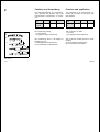
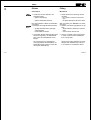
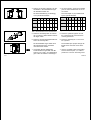
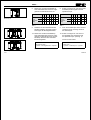
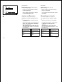
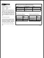
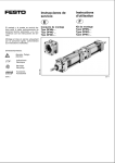
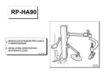
Einbau und Inbetriebnahme
nur von autorisiertem Fachpersonal,
gemäß Bedienungsanleitung.
Bedienungsanleitung
Operating
instructions
Montagebausatz
Typ DPNN -...
Typ DPNG -...
Typ DPNC-...
Assembly kit
Type DPNN -...
Type DPNG -...
Type DPNC-...
Fitting and commissioning to be
carried out by qualified personnel
only in accordance with the operating
instructions.
Es bedeuten/Symbols:
Warnung
Warning, Caution
Hinweis
Note
Zubehör
Accessories
9704 b
373 136
Recycling
Recycling
D/GB 1
DPNN-...
Bedienteile und Anschlüsse
1
Operating parts and
connections
1
2
1
2
Sechskantmutter 3
Flange 1
Threaded pin 2
Hexagon nut 3
3
Flansch
Gewindestift
9704 b
Bild 1/Fig. 1
D/GB 2
2
a)
a)
b)
A
BC
D
Hub1
b)
Funktion und Anwendung
Function and application
Der Montagebausatz ist vorgesehen,
zwei Zylinder des gleichen Typs und
Durchmessers miteinander zu verbinden.
This assembly kit is intended for connecting two cylinders of the same type
and diameter.
Zylindertyp
DNG-...
DNN-...
Montagebausatz
DPNG-... DPNN-...
DNC-...
Cylinder
type
DNG-...
DNN-...
DNC-...
DPNC-...
Assembly
kit
DPNG-... DPNN-... DPNC-...
Bild 2
Fig. 2
Die Verbindung erfolgt
- in einer Achse
- bei gegensinniger Hubrichtung.
The connection is made:
- in an axis
- with opposite stroke directions.
Die Verbindung dient in der Regel zur
Realisierung von
a) freitragenden Konstruktionen,
b) vier definierten Endpositionen.
The connection usually serves for implementing:
a) self-contained constructions,
b) four defined end positions.
Hub2
Hub1
Hub2
Bild 3/Fig. 3
9704 b
D/GB 3
DPNN-...
3
Einbau
Fitting
mechanisch
Mechanical
1. Achten Sie bei den Zylindern auf
folgende Punkte:
- gleicher Zylindertyp
1. Please observe the following with the
cylinders:
- the cylinders must be of the same
type
- the piston diameter must be the same.
- gleicher Kolbendurchmesser.
Bei Gewindestiften ohne rote Klebe-Beschichtung:
2. Beachten Sie folgende Kleberichtlinien:
- genügend Klebstoff auf gereinigte
Teile auftragen
- Hautkontakt vermeiden.
3. Verwenden Sie das beiliegende Schraubensicherungsmittel, um selbstständigem Lösen der Gewindestifte vorzubeugen.
Die Verwendung von Schraubensicherungsmittel bei Gewindestiften mit
Klebe-Beschichtung führt zu einer Minderung der Klebewirkung.
9704 b
With threaded pins withouth red adhesive layer:
2. Observe the following guidelines for glueing:
- Apply sufficient adhesive to cleaned
parts
- Avoid contact with the skin.
3. Use the enclosed screw locking agent
in order to prevent the threaded pins
from coming apart.
Using screw locking adhesive on threaded pins with adhesive layer will lead
to a reduction in the adhesive effect.
D/GB 4
4. Drehen Sie an jedem Zylinder vier Gewindestifte in die Gewindebohrungen
der Deckelschrauben ein.
Die Einschraubtiefe (A) ist abhängig
vom Zylinderdurchmesser:
Bild 4/Fig. 4
Nenn-Ø
32
40
50
63
80
DPNN- 10,5 10,5 12,5 13,5 17
...
Bild 6/Fig. 6
Rated-Ø 32
17
DPNN- 10.5 10.5 12.5 13.5 17
...
9
9,5
14 11,5 15,5 15,5
DPNC...
9
9,5
14
18
18
20
9704 b
40
50
63
80 100 125
17
DPNG...
9
9.5
14 11.5 15.5 15.5
DPNC...
9
9,5
14
13
18
18
20
Bild 5: Einschraubtiefe A des Gewindestifts
Fig. 5: Screw depth A of threaded pin
5. Plazieren Sie die Zylinder so zueinander, wie deren Luftanschlüsse zueinander liegen sollen.
5. Place the cylinders together so that
the compressed air connections are
correctly positioned.
6. Plazieren Sie den Montagebausatz auf
einem der zwei Zylinder.
6. Place the assembly kit on one of the
two cylinders.
Die Gewindestifte ragen dabei durch
die Flanschbohrungen und dürfen
nicht deformiert werden.
Bild 7/Fig. 7
The screw depth is (A) is determined
by the cylinder diameter.
100 125
DPNG...
13
4. On each cylinder, screw four threaded
pins into the threaded bores of the cover screws.
7. Verwenden Sie das beiliegende
Schraubensicherungsmittel unter Beachtung von Punkt 2, um selbstständigem Lösen der Muttern vorzubeugen.
The threaded pins project through the
flange bores and must not be deformed.
7. Use the enclosed screw locking adhesive and observe point 2, in order to
prevent the nuts from becoming loose.
D/GB 5
DPNN-...
8.
Drehen Sie auf die Gewindestifte je
eine Sechskantmutter mit dem vorgegebenen Anziehdrehmoment auf.
Nenn-Ø
Bild 8/Fig. 8
Bild 10/Fig. 10
32 40 50 63 80 100 125
Anzieh- DPNN 6
drehDPNG 8
moment
DPNC 5
[Nm]
6
8
8 15 15
8 15 15 18 18
5 13 13 30 30 40
8.
Screw a hexagon nut onto each of the
threaded pins and tighten with the
specified torque.
Rated-Ø
Tightening
torque
moment
[Nm]
Bild 9
Bild 9
9.
9.
Schieben Sie die Gewindestifte des
zweiten Zylinders durch die Flanschbohrungen des Montagebausatzes.
10. Drehen Sie auf die Gewindstifte je
eine Sechskantmutter mit dem vorgegebenen Anzeihdrehmoment auf (siehe Bild 9). Damit ist eine montierte
Einheit hergestellt.
Definition:
Montierte Einheit =
Zylinder + Montagebausatz + Zylinder
Bild 12
32 40 50 63 80 100125
DPNN 6
6
8
8 15 15
DPNG 8
8 15 15 18 18
DPNC
5 13 13 30 30 40
5
Push the threaded pins of the second
cylinder through the flange bores of
the assembly kit.
10. Screw a hexagon nut onto each of
the threaded pins and tighten with
the specified torque. (see Fig. 9).
The unit is then fitted.
Definition:
Fitted unit =
Cylinder + assembly kit + cylinder
Fig. 12
Bild 11/Fig. 11
9704 b
D/GB 6
a)
b)
pneumatisch
Bei Festliegen eines Kolbenstangenendes (Fixlagerung):
Pneumatic
When fixing a piston rod end
(fixed bearing):
• Achten Sie auf beweglich verlegte
Schlauchleitungen.
• Please observe fixed fitted tubing
which is moveable.
Der Zylindermantel führt in diesem
Fall eine Bewegung aus.
The cylinder barrel performs a movement here.
Bild 13/Fig. 13
4
Ausbau und Reparatur
Dismantling and repairs
Bei Bedarf schneller Zylinderwechsel:
The cylinder can be replaced quickly.
• Tauschen Sie die montierte Einheit
komplett aus.
• Replace the fitted unit completely.
Die Einbaumaße von montierten Einheiten der verschiedenen Zylindertypen sind identisch.
(Die Toleranzen nach DIN ISO 6431
und DIN/VDMA 24562 T1 sind dabei
zu beachten.)
Einbaumaß
montierte Einheit
=
Einbaumaß
montierte Einheit
Dimensions
mounted unit
=
Dimensions
mounted unit
DNG + DPNG +
DNG
=
DNN +DPNN +
DNN
DNG + DPNG +
DNG
=
DNN +DPNN +
DNN
DNC + DPNC +
DNC
=
DNG + DPNG +
DNG
DNC + DPNC +
DNC
=
DNG + DPNG +
DNG
Bild 14
9704 b
The fitting dimensions of fitted units
of different cylinder types are
identical.
(The tolerances as per DIN ISO
6431 and DIN/VDMA 24562 T1 must
be observed).
Fig. 14
D/GB 7
Postfach
D-73726 Esslingen
Telefon (++49) (0)711/347-0
Quelltext:
Version:
deutsch
9704 b
Alle Rechte, auch der Übersetzung, vorbehalten. Kein Teil des Werkes darf in
irgendeiner Form (Druck, Kopie, Microfilm oder einem anderen Verfahren)
ohne schriftliche Genehmigung der
Festo KG reproduziert oder unter Verwendung elektronischer Systeme verarbeitet, vervielfältigt oder verbreitet werden.
5
Störungsbeseitigung/Eliminating faults
Störung
Montagebausatz liegt nicht
plan am Zylinderdeckel an
mögliche Ursache
Schmutzpartikel auf den
Fügeflächen
Abhilfe
Reinigen der Fügeflächen
Fault
Assembly kit does not lie
flat on cylinder cover
Possible cause
Dirt particles on the joining
surfaces
Remedy
Clean the joining surfaces
Bild 15/Fig. 15
6
Technische Daten
Typ
Änderungen vorbehalten
All rights reserved, including translation
rights. No part of this publication may be
reproduced or transmitted in any form or
by any means, electronic, mechanical,
photocopying or otherwise, without the
prior written permission of Festo KG.
Zul.
Temperaturbereich
Werkstoffe
Einbaulage
Bild 16
DPNG-...
DPNN-...
DPNC-...
-20 ... + 80° C
AL / St
beliebig
Technical specifications
Type
Permitted
temperature range
Materials
Fitting position
DPNG-...
DPNN-...
DPNC-...
-20 ... + 80° C
AL / St
As desired
Fig. 16
We reserve the right to make alterations.
9704 b
D/GB 8