1
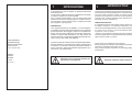
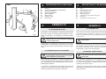
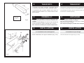
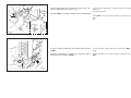
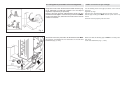
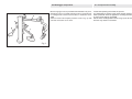
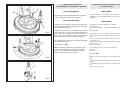
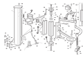
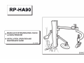
SOMMARIO
INDEX
1 - INTRODUZIONE'
1 - INTRODUCTION
..........................................................................................4
2 - DESCRIZIONE DELLA MACCHINA
2 - DESCRIPTION OF THE MACHINE
..........................................................................................5
3 - GENERALITA'
3 - GENERALS
..........................................................................................5
4 - TRASPORTO
4 - TRANSPORT
..........................................................................................6
5 - DISIMBALLO
5 - UNPACKING
..........................................................................................6
6 - INSTALLAZIONE
6 - INSTALLATION
6.1 Installazione sullo smontagomme
6.2 Collegamenti pneumatici allo smontag.
7.3 - Montaggio componenti
6.1 Installation on tyre-changer
6.2 Air connection to tyre-changer
7.3 Components assembly
7 - USO
7 - USE
7.1 - Smontaggio pneumatici
7.2 - Montaggio pneumatici
7.1 Removal Tyres
7.2 Mounting Tyres
8-RIPOSIZIONAMENTO
8- RESITING
..........................................................................................6
............................................................6
............................................................8
............................................................9
.......................................................................................10
...........................................................10
...........................................................11
.......................................................................................12
9-ACCANTONAMENTO
9- STORAGE
.......................................................................................12
10-ROTTAMAZIONE
10- SCRAPPING
.......................................................................................12
11-MANUTENZIONE
11- MAINTENANCE
.......................................................................................13
12-RICAMBI
12-SPARE PARTS
.......................................................................................14
1
INTRODUZIONE
Vi ringraziamo per aver acquistato un prodotto della Nostra
linea di accessori.
La macchina è realizzata attraverso l’applicazione dei migliori principi in rispetto al concetto di qualità.
Per un corretto funzionamento e per una lunga durata sarà
sufficiente osservare le semplici istruzioni contenute nel presente manuale che dovrà essere letto e compreso nel modo
più completo in ogni sua parte.
ANAGRAFICA
Una completa descrizione del “Modello” e il “N.ro di Matricola” faciliterà il servizio della Nostra assistenza e la spedizione
di parti di ricambio. Per maggiore chiarezza e comodità ricordiamo i dati del Vostra attrezzatura nel riquadro sottostante.
Qualora vi fossero delle discordanze fra i dati riportati nel
presente manuale e quelli sulla targhetta applicata alla macchina, faranno fede quelli sulla targhetta.
Casa costruttrice:
Manufactured by:
Maison constructrice:
Herstellerfirma:
Empresa fabricante:
Indirizzo:
Address:
Adresse:
Adresse:
Dirección:
Il presente manuale costituisce parte integrante del prodotto.
Prima di utilizzare lo smontagomme, leggere attentamente le
avvertenze e le istruzioni contenute nel presente libretto in
quanto forniscono importanti indicazioni riguardanti la sicurezza d’uso e la manutenzione.
Conservare con cura questo manuale per
ogni ulteriore consultazione
1
INTRODUCTION
Thank you for purchasing a product from the line of accessories.
The machine has been manufactured in accordance with the
very best quality principles. Follow the simple instructions
provided in this manual to ensure the correct operation and
long life of the machine. Read the entire manual thoroughly
and make sure you understand it.
IDENTIFICATION DATA
A complete description of the “Model” and the “Serial number”
will make it easier for our technical assistance to provide
service and will facilitate delivery of any required spare parts.
For clarity and convenience, we have inserted the data of the
equipment in the box below.
If there is any discrepancy between the data provided in this
manual and that shown on the plate fixed to the machine, the
latter should be taken as correct.
This manual is an integral part of the product.
Before using the tyre changer, read carefully the warnings and
instructions contained in this manual since
they provide important information on operating safety and
maintenance.
Keep this manual for further reference.
4
HP 1
2
1
2
3
8
1)
2)
3)
4)
5)
6)
7)
8)
DESCRIZIONE DELLA MACCHINA
Braccio 1
Comando azionamento salita/discesa
Braccio premitallone
Utensile premitallone
Disco alzatalloni
Braccio disco
Utensile a rullo
Braccio rullo
2
1)
2)
3)
4)
5)
6)
7)
8)
DESCRIPTION OF THE MACHINE
Arm 1
Lifting/lowering control
Bear pressing arm
Bead pressing tool
Bead lifting disk
Operating arm with bead lifting disk
Roller tool
Operating arm with roller tool
6
3
7
4
5
Fig. 1
GENERALITA'
3
GENERALS
3.1 DESTINAZIONE D’USO.
3.1 INTENDED USE
L'accessorio è stato progettato e realizzato esclusivamente
per essere montato su smontagomme automatici, per agevolare lo smontaggio e il montaggio dei pneumatici dai/sui
cerchi.
This accessory has been designed and manufactured
exclusively for being installed on automatic tyre-changers
inorder to facilitate removing and mounting of tyres from/
onto the rims.
Qualsiasi altro uso è da considerarsi improprio
e quindi irragionevole
In particolare il costruttore non può essere considerato
responsabile per eventuali danni causati da usi non esplicati in questo manuale e quindi impropri, erronei ed irragionevoli.
3.2 NORME GENERALI DI SICUREZZA.
Any other use is to be considered incorrect and
unreasonable.
In particular the manufacturer cannot be held responsible for
any damage caused throught the use for purposes other
than those specified in this manual, and therefore
inappropriate, incorrect and unreasonable.
3.2 GENERAL SAFETY RULES
L’uso delle attrezzature è consentito solo ed
esclusivamente a personale esperto, appositamente addestrato ed autorizzato.
The use of these accessories is permitted
only and exclusively to trained and authorized
expert staff.
Ogni e qualsiasi manomissione o modifica dell’apparecchiatura non preventivamente autorizzate dal costruttore, sollevano quest’ultimo da ogni responsabilità per danni derivati o
riferibili agli atti suddetti.
Any tampering or modification to the equipment carried
out without the manufacturer's prior authorization will free
him from all responsibility for damage caused directly or
indirectly by the above actions.
La rimozione o manomissione dei dispositivi di sicurezza
comporta la decadenza immediata della garanzia e la
violazione delle Norme Europee per la Sicurezza.
Removing or tampering with safety devices immediately
invalidates the warranty and it is in contravention of European
Safety Standards.
5
380
4
130
0
100
0
TRASPORTO
4
TRANSPORT
L'accessorio deve essere trasportato nell'imballo originale
e mantenuto nella posizione indicata sull'imballo stesso.
The accessory must be transported in its original package
and kept in the position shown on the package itself.
Lo spostamento dell' accessorio imballato deve essere effettuato inforcando l'imballo con un carrello elevatore di adeguate capacità.
The packaged accessory may be moved by means of a
fork lift truck of suitable capacity.
500
5
Kg.88
Fig. 2
Dopo aver tolto l'imballaggio assicurarsi dell'integrità della
macchina controllando che non vi siano parti visibilmente danneggiate.
Gli elementi dell'imballaggio non devono essere lasciati alla
portata dei bambini in quanto potenziali fonti di pericolo.
N.B.: Conservare l'imballo per eventuali trasporti futuri.
6
A
DISIMBALLO
INSTALLAZIONE
6.1 Installazione sullo smontagomme
Svitare il lubrificatore ed il supporto lubrificatore (Fig. 3 rif.A)
5
UNPACKING
Once the packing material has been removed, check the
machine visually for any signs of damage.
Keep the packing materials out of the reach of children as
they can be a source of danger.
N.B.: Keep the packing for possible future transport.
6
INSTALLATION
6.1 Installation on tyre-changer
Unscrew lubricator and support (Fig. 3 ref.A).
Fig. 3
6
D
E
Inserire negli appositi fori le piastrine di supporto (D) e fissarle col dado basso M10 come in fig. 4
F
Set the support plates (D) in relevant holes and fix them by
means of
low nut M10 (Fig.4)
Montare l' HP 1 sui supporti e fissarlo tramite i dadi M10 (E)
E
D
Mount HP1 onto the supports and fix it by means of nuts
M10
(E)
E
Fig. 4
Avvitare il supporto lubrificatore (se presente) alla carcassa
di HP 1
Fix the lubricator support (if any) by screws to the HP1
body.
Fissare il lubrificatore al supporto (se presente) oppure
direttamente alla carcassa di HP 1.
Fix the lubricator to the support (if any) or directly to the
HP1.
Fig. 5
7
6.2 Collegamenti pneumatici allo smontagomme.
6.2 Air connection to tyre-changer
Recuperare il tubo rilsan di alimentazione della macchina (Fig.
6) ed, utilizzando un taglia tubi, tagliarlo 5 cm circa dopo il
regolatore di pressione (se presente).
Inserire il raccordo, presente nella dotazione del kit, nel tubo
precedentemente tagliato. Inserire il tubo proveniente dall'HP1
nel raccordo rapido di 6, assicurarsi che il tubo entri in manera
corretta nel raccordo.
Cut the feeding rilsan hose (fig.6) at about 5 cm. from the
pressure
regulator (if any).
Set the union, delivered with the kit, into the cut hose.
Set the pipe coming from HP1 into the quick union of 6,
make
Sure the hose fit properly into the union.
Assicurarsi che il tubo pneumatico di alimentazione dell' HP1
sia inserito correttamente nel raccordo al di sotto del
basamento (Fig. 7, rif. A)
Make sure that the feeding pipe of HP1 is correctly set into
the union
under the baseframe (Fig. 7, ref.A)
Fig. 6
Fig. 7
8
6.3 Montaggio componenti.
Montare il gruppo braccio premitallone H infilandolo nel perno,
utilizzando la vite e le rondelle I serrare il tutto in modo adeguato. Analogamente montare il braccio disco L fissandolo con le
viti M.
Infilare il braccio rullo N (nella posizione come in fig. 8) nella
sua sede e bloccarlo con le viti P.
H
I
P
6.3 Components assembly
Fit the bead pressing arm H into the pin and
fix it adequately by means of the screw and the washers I.
Same procedure must be applied for mounting the disk arm
L; this must be fixed by screws M.
Set the roller arm N (position shown in fig. 8) into its housing
and lock it by means of screws P.
M
N
L
Fig. 8
9
7
4
USO
Fig. 9
7.1-REMOVAL OF EXTRALOW PROFILED TYRES
OR "RACING"TYRES
TALLONE SUPERIORE
UPPER BEAD
Y
Fig. 13
Fig. 10
Nel caso si presentino difficoltà utilizzare il premitallone
(4)per tenere premuto il cerchio sulle griffe
dell'autocentrante e facilitarne il bloccaggio (se necessario utilizzare un cono di centraggio per facilitale l'operazione) (Fig. 9)
Posizionare la torretta integrale come da procedura
standard di smontaggio riportata sul manuale d'uso e
manutenzione dello smontagomme (se necessario
premere con il rullo sulla gomma per facilitare l'operatore) fig. 8
Y
Posizionare (Fig.10) il rullo alla destra della torretta e il
premitallone (4) (Fig. 11) dalla parte opposta, in modo
che premano leggermente il pneumatico verso il basso, per facilitare l'inserimento della leva alzatalloni (Y).
Posizionare il premitallone rif.4 fig.11 dalla parte opposta all'utensile per agevolare il caricamento del tallone
della gomma sull'utensile usando la leva alzatalloni
(Y)
Una volta abbassata la leva eportato il tallone del pneumatico sulla torretta seguire la procedura standard di
smontaggio.
TALLONE INFERIORE
4
Fig. 11
USE
7.1-SMONTAGGIO PNEUMATICI
ULTRARIBASSATI O CON PROFILO "RACING"
Bloccare il cerchio sul piatto autocentrante come indicato sul manuale d'uso e manutenzione dello smontagomme.
Fig. 12
7
Seguire la procedura standard per lo smontaggio definitivo del pneumatico, aiutandosi con il disco alzatalloni
per sostenere il pneumatico in corrispondenza del canale del cerchio (Fig.12).
In questo modo viene facilitato l'inserimento e il
caricamento del tallone della gomma sull'utensile da
parte della leva alzatalloni Y (Fig.13).
Lock the rim onto the turntable as shown in
tyrechanger’s
installation, use and maintenance guide.
In case of difficulty, use the bead-pressing tool (4)
to keep the rim pressed onto the turntable
clamps and facilitate its locking (if necessary, use
the
centering cone to facilitate the operation) (fig.9)
Position the mounting head as indicated by
standard
proceeding for tyre removal inside the installation,
use
and maintenance guide (if necessary, press the
roller
against tyre to facilitate the operation) (fig. 8)
Position (Fig. 10) the roller at the right side of the
mounting head and the bead-pressing tool (4)
(fig.11)
at the opposite side, so that they press slightly the
tyre
downwards, in order to facilitate introduction of the
bead lifting
lever (Y).
Position the bead-pressing tool (4) (fig.11) at the
tool opposite
side to facilitate tyre bead positioning on mounting
tool by means
of the bead lifting lever (Y)
Once the lever is down and the bead is set onto the
tool follow
removing standard procedure.
LOWER BEAD
Follow standard proceedings for tyre final removal
and
use the bead-lifting disk for keeping the tyre at the
same level of rim’s groove (Fig.12))
This will facilitate tyre bead positioning on tool by
means of the bead-lifting (Fig. 13).
10
7.2 - MONTAGGIO PNEUMATICI
ULTRARIBASSATI O CON PROFILO "RACING"
7.2 - MOUNTING EXTRALOW PROFILED TYRES
OR "RACING"TYRES
TALLONE INFERIORE
LOWER BEAD
8
X
Seguire la procedura standard descritta sul manuale
di uso e manutenzione dello smontagomme
Follow standard proceedings described in the
Installation, Use and Maintenance guide of TyreChanger.
TALLONE SUPERIORE
Posizionare il pneumatico come descritto nella procedura standard descritta sul manuale di uso e manutenzione dello smontagomme
4
Fig. 13
Posizionare il rullo (8) e il premitallone (4) a destra
della torretta (X) in modo che il tallone superiore del
pneumatico sia in corrispondenza del canale del cerchio (Fig.13). Per regolare l'altezza del premitallone
svitare o avvitare la vite come in figura 10 pag. 9.
Far ruotare l'autocentrante fino al completo montaggio
del pneumatico (Fig.14).
Disimpegnare l' HP1
N.B. Se durante l'operazione il premitallone (4) non
preme in modo adeguato (preme troppo o troppo
poco), occorre regolare la sua altezza avvitando o
svitando la vite come indicato in fig. 15
UPPER BEAD
Position the tyre as described by standard
proceedings
inside the Installation, Use and Maintenance guide
of
Tyre-Changer.
Position the roller (8) and the bead-pressing tool (4)
at the right side of the mounting head (X) in a way
that
the tyre upper bead stays at the same level of rim’s
groove (Fig. 13)
To adjust the height of bead-pressing tool, screw
down or out as
Per fig. 10, page 9.
Let turntable turn until the tyre is completely
mounted
(Fig.14).
Release HP1.
Fig. 14
Note: if, during the operation, the bead-pressing tool
(4) is
not pressing the tool adequately (too much or too
few), it
is necessary to adjust its height by screwing down or
out
the screw as per fig. 15.
Fig. 15
11
8
RIPOSIZIONAMENTO
Fare riferimento al manuale della macchina su cui è montato l' HP1.
9
ACCANTONAMENTO
In caso di accantonamento per lungo periodo di tempo è necessario:
• Scollegare tutte le fonti di alimentazione
• Ingrassare le guide di scorrimento dei dischi alzatallone,
del tampone e del rullo per evitarne l'ossidazione
10
ROTTAMAZIONE
Qualora si decida di rottamare gli accessori, si raccomanda
di renderli inoperanti:
• Scollegando le fonti di alimentazione.
• Asportando tutti i materiali NON ferrosi e smaltendoli
secondo le leggi nazionali vigenti.
• Rottamando il resto come materiale ferroso.
8
RESITING
Make reference to the Installation guide of the machine,
on which HP1is installed.
9
STORAGE
In the event of storage for long periods of time, be sure to:
• disconnect all power sources.
• grease the clamp sliding guides of bead-lifting disks, pad
and roller to prevent them from oxiding.
10
SCRAPPING
If you decide to scrap the accessories, be sure to make them
inoperative by:
• Disconnecting them from all power sources.
• Remove all NON-ferrous materials and dispose of them as
prescribed by national law.
• Scrap the rest as ferrous material.
12
11
MANUTENZIONE
La manutenzione è sempre vietata a personale
non autorizzato
11
MAINTENANCE
Unauthorized staff may not carry out
maintenance work.
La manutenzione regolare, come da istruzioni, è fondamentale per un corretto funzionamento e una lunga durata dello
smontagomme
Regular maintenance as described in the instructions is
essential for correct operation and a long lifetime of the
machine.
Se la manutenzione non viene effettuata regolarmente, il funzionamento e l'affidabilità della macchina possono essere
compromesse, a rischio sia dell'operatore che di terzi.
If maintenance is not carried out regularly, the operation and
reliability of the machine may be compromised, thus placing
the operator and anyone else in the vicinity at risk.
Prima di effettuare qualsiasi intervento di manutenzione, disinserire l'allacciamento elettrico,
scollegando la spina, e quello pneumatico chiudendo il rubinetto.
Inoltre, per scaricare l'aria in pressione dal circuito, è necessario effettuare 3 - 4 stallonature
a vuoto premendo il pedale sullo smontagomme.
Le parti difettose devono essere sostituite esclusivamente da
personale esperto e con pezzi originali indicati dal catalogo
parti di ricambio.
La rimozione o manomissione dei dispositivi di sicurezza comporta una violazione delle Norme Europee sulla Sicurezza.
In particolare il costruttore non è imputabile per
reclami derivanti dall'uso di ricambi non originali o per danni causati dalla rimozione o manomissione dei sistemi di sicurezza.
OPERAZIONI DI MANUTENZIONE:
Pulire settimanalmente e ingrassare le guide di scorrimento.
Per il resto, fare riferimento al manuale d'uso e manutenzione dello smontagomme sui cui è montato l'HP1
Before carrying out any maintenance work,
disconnect the plug of electric supply and turn
off the tap for pneumatic supplies.
Moreover, it is necessary to break the bead
loadless 3-4 times in order to let the air in
pressure go out of the circuit.
Defective parts must be replaced exclusively by expert staff
using the manufacturer's spare parts indicated in the spare
parts catalogue.
Removing or tampering with safety devices represents a
contravention of European Safety Standards.
In particular the manufacturer shall not be held
responsible for complaints deriving from the
use of spare parts made by other
manufacturers or for damage caused by
tampering or removal of safety systems.
MAINTENANCE OPERATIONS:
Weekly clean and grease the sliding guides.
For the rest, make reference to the Installation, Use and
Maintenance guide of the tyre-changer, on which HP1
is mounted.
13
PARTI DI RICAMBIO
SPARE PARTS
14
15
1
6618542
BASAMENTO HP1 COMPLETO -NERO
HP1 POST
COLONNE HP1
HP1 SAEULE
2
6618557
CARRELLO SX HP1 -NERO
LEFT CARRIAGE
CHARIOT GAUCHE
LINKER SCHLITTEN
3
6618546
CARRELLO DX HP1 -NERO
RIGHT CARRIAGE
CHARIOT DROITE
RECHTER SCHLITTEN
4
2018561
GR.CILINDRO P.A. XP
CYLINDER UNIT
GR. VERIN
ZYLINDER
5
6618523
BRACCIO 1 HP1 -NERO
ARM 1
BRAS 1
ARM 1
6
6618522
BRACCIO RULLO HP1 -NERO
ROLLER ARM
BRAS ROULEAU
ROLLENARM
7
3016688
VITE SPECIALE TAMPONE P.A. BOSS 1
SPECIAL SCREW
VIS SPECIAL
SONDERSCHRAUBE
8
6618528
BRACCIO ATTACCO DISCO HP1 -NERO
DISK CONNECT. ARM
BRAS CONNEX. DISQUE
SCHEIBENVERBINDUNGSARM
9
3006886
DISCO STALLONATORE
BEAD BREAKING DISK
DISQUE DECOLLE-TALONS
WULSTABDRUECKPLATTE
10
3008404
PREMITALLONE NYLON NERO
BEAD-PRESSING TOOL
PRESSE-TALON
WULSTDRUECKER
11
2012683
GR.IMPUGNATURA+VITE STEI M10
HANDLE+SCREW
POIGNEE+VIS
HANDGRIFF+SCHRAUBE
12
3006862
PERNO SUP.DISCO ST.BRUNITO
DISK PIN
AXE DISQUE
PLATTENSTIFT
13
2118543
BRACCIO SUPPORTO RULLO COMPLETO -ZNT V.
ROLLER SUPPORT ARM
BRAS SUPPORT ROULEAU
ROLLENTRAGARM
14
3008433
RULLO ST.D.100 L120 NYLON NERO
ROLLER D.102 L=120
GALET D.102 L=120
ROLLE D.102 L=120
15
2118555
GUIDA BRACCIO ESAGONALE -ZNT V.
HEX. ARM GUIDE
GUIDE BRAS HEXAGONAL
ARMFUEHRUNG
16
3002311
RONDELLA D.10,5x45x4 -ZINCATA
WASHER D.10,5x45x4
RONDELLE D.10,5x45x4
BEILAGSSCHEIBE D.10,5x45x4
17
4399946
VITE TE 8x16 8.8
SCREW 8x16
VIS 8x16
SCHRAUBE 8x16
18
4195524
RACCORDO 6590-6 S.R.PASSAPARETE
UNION 6590-6
RACCORD 6590-6
ANSCHLUSS 6590-6
19
3018815
SPIRALE POLIUR. 6X4 L=1000
SPIRAL HOSE 6X4 L=1000
TUYAU SPIRALE 6X4 L=1000
SPIRALSCHLAUCH 6X4 L=1000
20
4197949
OGIVA IR 100 6/4 OTTONE
NOSE IR 100 6/4
CAPOT IR 100 6/4
HAUBE IR 100 6/4
21
3018551
CARENATURA VALVOLA P.A. HP
VALVE COVER
PROTECTION SOUPAPE
VENTILSCHUTZ
22
3008944Y
DECALCO FRECCIA + UP GIALLO
UP/ARROW STICKER
AUTOCOLLANT FLECHE/UP
UP/PFEIL AUFKLEBER
23
3010284
POMOLO D.14x45 FORO M5 ZNT
KNOB D.14X45 M5
POMMEAU D.14x45 M5
KUGELGRIFF D.14x45 M5
24
2006996
GR.VALVOLA HELP-PRESS ARM
VALVE
SOUPAPE
VENTIL
25
4399297
VITE TCEI M 8x130 8.8
SCREW 8x130
VIS 8x130
SCHRAUBE 8x130
26
4399976
DADO M 8
NUT M8
ECROU M8
MUTTER M8
27
4399068
VITE TE 8x40 8.8 PF
SCREW 8x40
VIS 8x40
SCHRAUBE 8x40
28
4399966
VITE TE 10x20 8.8
SCREW 10x20
VIS 10x20
SCHRAUBE 10x20
29
3018829
RONDELLA X BRACCIO DIRITTO HP1
WASHER
RONDELLE
BEILAGSSCHEIBE
30
4399954
VITE TCEI M 8x20
SCREW 8x20
VIS 8x20
SCHRAUBE 8x20
31
4399786
VITE TE 10x30 8.8
SCREW 10x30
VIS 10x30
SCHRAUBE 10x30
32
4399378
RONDELLA 10 (10,5x21x2)
WASHER D.10 (10,5x21x2)
RONDELLE D.10 (10,5x21x2)
BEILAGSSCHEIBE 10 (10,5x21x2)
33
2108784
VITE ANTIROTAZIONE H.3-BRUN.
ANTIROTATION SCREW H.3
VIS ANTIROTATION H.3
DREHSICHERE SCHRAUBE H.3
34
2110301
CAVALLOTTO FISS. H3 S113-BRUN.
U BOLT
CRAMPILLON
KRAMPE
35
2108782
CAVALLOTTO FISSAGGIO H.3-BRUN.
U BOLT
CRAMPILLON
KRAMPE
36
6610304
STAFFA SUPP. H4 S113-NERO B.
SUPPORT
ETRIER
STUETZE
16
37
4399827
VITE TE 8x20 8.8
SCREW 8x20
VIS 8x20
SCHRAUBE 8X20
38
4395669
RONDELLA 10 (11x40x2,5)
WASHER 10 (11x40x2,5)
RONDELLE 10 (11x40x2,5)
BEILAGSSCHEIBE 10 (11x40x2,5)
39
4399966
VITE TE 10x20 8.8
SCREW 10x20
VIS 10x20
SCHRAUBE 10x20
40
3018535
FLANGIA CILINDRO D.100
CYLINDER FLANGE D.100
BRIDE VERIN D.100
ZYLINDERFLANSCH D.100
41
4294385
ANELLO OR 239 D.91,67X3,5
O-RING 239 D.91,67X3,5
JOINT OR 239 D.91,67X3,5
O-RING 239 D.91,67X3,5
42
3018562
PISTONE TDUO P 100-69 -LAV
PISTON TDUO P 100-69 -LAV
PISTON TDUO P 100-69 -LAV
KOLBEN TDUO P 100-69 -LAV
43
4296841
NASTRO DI GUIDA ASTA CILINDRO D.40
NYLON GUIDE
GUIDAGE EN NYLON
NYLONFUEHRUNG
44
3018533
SEMISTELO MASCHIO D.40
MALE SHAFT D.40
TIGE MALE D.40
GEWINDEWELLE D.40
45
3018532
SEMISTELO FEMMINA D.40
FEMALE SHAFT D.40
TIGE FEMELLE D.40
HOHLWELLE D.40
46
4198618
RACCORDO 6522 1/8"-6
UNION 1/8"
RACCORD 1/8"
ANSCHLUSS 1/8"
47
3016150
TUBO ELASTOLAN 6X4 L=1500 NEUTRO
HOSE 6X4 L=1500 NEUTRAL
TUYAU 6X4 L=1500 NEUTRE
SCHLAUCH 6X4 L=1500 NEUTRAL
48
3014456
TUBO ELASTOLAN 6X4 L=1450 AZZURRO
HOSE 6x4 L=1450
TUYAU 6x4 L=1450
SCHLAUCH 6x4 L=1450
49
3014451
TUBO ELASTOLAN 6X4 L=1100
HOSE 6x4 L=1100
TUYAU 6x4 L=1100
SCHLAUCH 6x4 L=1100
50
4198778
RACCORDO 6410 1/8"-8 S.RAPIDO
QUICK UNION 1/8"
RACCORD RAPIDE 1/8"
SCHNELLANSCHLUSS 1/8"
51
4198172
RACCORDO 6463 1/8"-6
UNION 1/8"
RACCORD 1/8"
ANSCHLUSS 1/8"
52
3001629
TUBO ELASTOLAN 6X4 L=800
HOSE 6x4 L=800
TUYAU 6x4 L=800
SCHLAUCH 6x4 L=800
53
4399969
DADO M10 6S ALTO
NUT M10
ECROU M10
MUTTER M10
54
4399897
VITE TE 4x25 8.8 PF
SCREW 4x25
VIS 4x25
SCHRAUBE 4x25
55
4399863
RONDELLA 8 (9x24x2)
WASHER 8 (9x24x2)
RONDELLE 8 (9x24x2)
BEILAGSSCHEIBE 8 (9x24x2)
56
3018534
CAMICIA CILINDRO PA XP
CYLINDER LINER
CHEMISE VERIN
ZYLINDERMANTEL
17