1
Operating Instructions
Signal conditioning and display
instrument for level sensors
VEGAMET 624
4 … 20 mA/HART
Document ID: 28969
Contents
Contents
1
About this document
1.1 Function ........................................................................................................................... 4
1.2 Target group ..................................................................................................................... 4
1.3 Symbolism used ............................................................................................................... 4
2
For your safety
2.1 Authorised personnel ....................................................................................................... 5
2.2 Appropriate use ................................................................................................................ 5
2.3 Warning about incorrect use............................................................................................. 5
2.4 General safety instructions ............................................................................................... 5
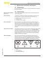
2.5 Safety label on the instrument .......................................................................................... 5
2.6 CE conformity................................................................................................................... 6
2.7 Safety instructions for Ex areas ........................................................................................ 6
2.8 Environmental instructions ............................................................................................... 6
3
Product description
3.1 Configuration .................................................................................................................... 7
3.2 Principle of operation........................................................................................................ 8
3.3 Adjustment ....................................................................................................................... 8
3.4 Packaging, transport and storage ..................................................................................... 9
4
Mounting
4.1 General instructions ....................................................................................................... 10
4.2 Mounting instructions ..................................................................................................... 10
5
Connecting to power supply
5.1 Preparing the connection ............................................................................................... 12
5.2 Connection procedure .................................................................................................... 12
5.3 Wiring plan ..................................................................................................................... 14
6
Setup with the integrated display and adjustment unit
6.1 Adjustment system ......................................................................................................... 16
6.2 Setup steps .................................................................................................................... 17
6.3 Menu schematic ............................................................................................................. 26
7
Setup with PACTware
7.1 Connect the PC .............................................................................................................. 32
7.2 Parameter adjustment with PACTware ............................................................................ 34
7.3 Setup web server/e-mail, remote enquiry ....................................................................... 35
8
Application examples
8.1 Levelmeasurementinacylindricaltankwithoverfillprotection/dryrunprotection ......... 36
8.2 Pump control 1/2 (running time controlled) ..................................................................... 37
8.3 Tendency recognition ..................................................................................................... 39
8.4 Flow measurement ......................................................................................................... 40
10 Dismounting
10.1 Dismounting steps.......................................................................................................... 46
2
VEGAMET 624 • 4 … 20 mA/HART
28969-EN-130701
9 Maintenanceandfaultrectification
9.1 Maintenance .................................................................................................................. 43
9.2 Rectify faults ................................................................................................................... 43
9.3 Instrument repair ............................................................................................................ 45
Contents
10.2 Disposal ......................................................................................................................... 46
28969-EN-130701
11 Supplement
11.1 Technical data ................................................................................................................ 47
11.2 Overview applications/functionality ................................................................................ 50
11.3 Dimensions .................................................................................................................... 51
Supplementary documentation
Information:
Supplementary documents appropriate to the ordered version come
withthedelivery.Youcanfindthemlistedinchapter"Product description".
Editing status: 2013-06-18
VEGAMET 624 • 4 … 20 mA/HART
3
1 About this document
1
About this document
1.1
Function
1.2
Target group
1.3
Symbolism used
This operating instructions manual provides all the information you
need for mounting, connection and setup as well as important instructionsformaintenanceandfaultrectification.Pleasereadthisinformation before putting the instrument into operation and keep this manual
accessible in the immediate vicinity of the device.
This operating instructions manual is directed to trained specialist
personnel. The contents of this manual should be made available to
these personnel and put into practice by them.
Information, tip, note
This symbol indicates helpful additional information.
Caution: If this warning is ignored, faults or malfunctions can result.
Warning: If this warning is ignored, injury to persons and/or serious
damage to the instrument can result.
Danger: If this warning is ignored, serious injury to persons and/or
destruction of the instrument can result.
•
→
1
Ex applications
This symbol indicates special instructions for Ex applications.
List
The dot set in front indicates a list with no implied sequence.
Action
This arrow indicates a single action.
Sequence of actions
Numbers set in front indicate successive steps in a procedure.
Battery disposal
This symbol indicates special information about the disposal of batteries and accumulators.
28969-EN-130701
4
VEGAMET 624 • 4 … 20 mA/HART
2 For your safety
2
For your safety
2.1
Authorised personnel
All operations described in this operating instructions manual must
be carried out only by trained specialist personnel authorised by the
plant operator.
During work on and with the device the required personal protective
equipment must always be worn.
2.2
Appropriate use
VEGAMET 624 is a universal signal conditioning instrument and
power supply unit for connection of a 4 … 20 mA/HART sensor.
Youcanfinddetailedinformationontheapplicationrangeinchapter
"Product description".
Operational reliability is ensured only if the instrument is properly
usedaccordingtothespecificationsintheoperatinginstructions
manual as well as possible supplementary instructions.
For safety and warranty reasons, any invasive work on the device
beyond that described in the operating instructions manual may be
carried out only by personnel authorised by the manufacturer. Arbitraryconversionsormodificationsareexplicitlyforbidden.
2.3
Warning about incorrect use
2.4
General safety instructions
Inappropriate or incorrect use of the instrument can give rise to
application-specifichazards,e.g.vesseloverfillordamagetosystem
components through incorrect mounting or adjustment.
This is a high-tech instrument requiring the strict observance of standard regulations and guidelines. The user must take note of the safety
instructionsinthisoperatinginstructionsmanual,thecountry-specific
installation standards as well as all prevailing safety regulations and
accident prevention rules.
Theinstrumentmustonlybeoperatedinatechnicallyflawlessand
reliable condition. The operator is responsible for trouble-free operation of the instrument.
During the entire duration of use, the user is obliged to determine the
compliance of the necessary occupational safety measures with the
current valid rules and regulations and also take note of new regulations.
28969-EN-130701
2.5
Safety label on the instrument
The safety approval markings and safety tips on the device must be
observed.
VEGAMET 624 • 4 … 20 mA/HART
5
2 For your safety
2.6
CE conformity
ThedevicefulfillsthelegalrequirementsoftheapplicableECguidelines.ByaffixingtheCEmarking,weconfirmsuccessfultestingofthe
product.
YoucanfindtheCECertificateofConformityinthedownloadsection
of our homepage.
Electromagnetic compatibility
The instrument is designed for use in an industrial environment.
Nevertheless, electromagnetic interference from electrical conductors
and radiated emissions must be taken into account, as is usual with a
class A instrument according to EN 61326-1. If the instrument is used
inadifferentenvironment,itselectromagneticcompatibilitywithother
devices must be ensured by suitable measures.
2.7
Safety instructions for Ex areas
2.8
Environmental instructions
PleasenotetheEx-specificsafetyinformationforinstallationandoperation in Ex areas. These safety instructions are part of the operating
instructions manual and come with the Ex-approved instruments.
Protection of the environment is one of our most important duties.
That is why we have introduced an environment management system
with the goal of continuously improving company environmental protection.Theenvironmentmanagementsystemiscertifiedaccording
to DIN EN ISO 14001.
Pleasehelpusfulfillthisobligationbyobservingtheenvironmental
instructions in this manual:
•
•
Chapter"Packaging, transport and storage"
Chapter"Disposal"
28969-EN-130701
6
VEGAMET 624 • 4 … 20 mA/HART
3 Product description
3
Product description
3.1 Configuration
Scope of delivery
The scope of delivery encompasses:
Constituent parts
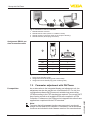
The VEGAMET 624 consists of the components:
•
•
•
•
•
•
•
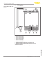
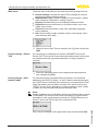
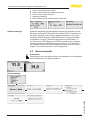
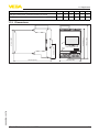
VEGAMET 624 signal conditioning instrument
Terminal socket
Coded pins and bridges
RS232 modem connection cable (optional)
Documentation
– this operating instructions manual
– Supplementaryinstruction30325"RS232/Ethernet connection"
(optional)
– Supplementaryinstructionsmanual30768"Modbus-TCP,
VEGA ASCII protocol"(optional)
– Ex-specific"Safety instructions"(withExversions)
– ifnecessary,furthercertificates
VEGAMET 624 signal conditioning instrument with display and
adjustment unit in the front
Terminal socket
1
1
2
3
4
5
6
7
8
2
1
2
3
3
COM
ESC
6
4
Ser. No.
12345678
VEGAMET
9 10
5
OK
on
17 18
11 12
20 21 22
13 14
15 16
23 24 25 26 27 28
Fig. 1: VEGAMET 624
1
2
3
4
5
6
28969-EN-130701
Type plate
Ex separating chamber with Ex version
VEGAMET 624
Display and adjustment unit
Communication interface for VEGACONNECT (I²C)
RS232 or Ethernet interface (optional)
Terminal socket
Thenameplatecontainsthemostimportantdataforidentificationand
use of the instrument:
•
•
•
•
Article number
Serial number
Technical data
Article numbers, documentation
VEGAMET 624 • 4 … 20 mA/HART
7
3 Product description
The order data and the documentation of the instrument can be
retrieved by means of the instrument serial number on the type label.
To do this, go to www.vega.com,"VEGA Tools"and"serial number
search".
Application area
3.2
Principle of operation
VEGAMET 624 is a universal signal conditioning instrument for a
variety of applications such as level, gauge and process pressure
measurement. At the same time, it can serve as power supply unit for
connected sensors. VEGAMET 624 is designed for connection of any
4 … 20 mA/HART sensor.
On instruments with one of the optional interfaces (RS232/Ethernet),
the measured values can be retrieved via modem or network and
displayed by means of a web browser or WEB-VV. It is also possible
to send measured values and messages via e-mail/SMS. The use of
VEGAMET 624 is particularly suitable for stocktaking, VMI (Vendor
Managed Inventory) and remote enquiry.
Functional principle
The VEGAMET 624 signal conditioning instrument can power connected sensors and process their measured signals. The requested
parameter is displayed and also sent to the integrated current outputs
for further processing. Hence the measured signal can be transferred
to a remote indicating unit or a superordinate control system. Three
level relays for control of pumps or other actuators are also integrated.
Voltage supply
Wide-range power supply unit with 20 … 253 V AC/DC for world-wide
use.
Detailed information about the power supply can be found in chapter
"Technical data".
3.3
Adjustment
The instrument can be adjusted with the following adjustment media:
•
•
With integrated display and adjustment unit
an adjustment software according to FDT/DTM standard, e.g.
PACTware and a Windows PC
The entered parameters are generally saved in VEGAMET 624, when
used with PACTware and PC also optionally in the PC.
Information:
When using PACTware and the corresponding VEGA DTM, additional
settings can be carried out which are not possible or only partly possible with the integrated display and adjustment unit. When using an
adjustment software, you either need one of the integrated interfaces
(RS232/Ethernet) or the interface converter VEGACONNECT.
8
VEGAMET 624 • 4 … 20 mA/HART
28969-EN-130701
Further instructions for setting up the web server and e-mail functions
can be found in the online help of PACTware or the VEGAMET 624
DTMsaswellastheoperatinginstructionsmanual"RS232/Ethernet
connection".
3 Product description
Packaging
3.4
Packaging, transport and storage
Your instrument was protected by packaging during transport. Its
capacity to handle normal loads during transport is assured by a test
based on ISO 4180.
The packaging of standard instruments consists of environmentfriendly, recyclable cardboard. For special versions, PE foam or PE
foil is also used. Dispose of the packaging material via specialised
recycling companies.
Transport
Transport must be carried out under consideration of the notes on the
transport packaging. Nonobservance of these instructions can cause
damage to the device.
Transport inspection
The delivery must be checked for completeness and possible transit
damage immediately at receipt. Ascertained transit damage or concealed defects must be appropriately dealt with.
Storage
Up to the time of installation, the packages must be left closed and
stored according to the orientation and storage markings on the
outside.
Unless otherwise indicated, the packages must be stored only under
the following conditions:
•
Not in the open
Dry and dust free
Not exposed to corrosive media
Protected against solar radiation
Avoiding mechanical shock and vibration
Storageandtransporttemperatureseechapter"Supplement Technical data - Ambient conditions"
Relative humidity 20 … 85 %
28969-EN-130701
Storage and transport
temperature
•
•
•
•
•
•
VEGAMET 624 • 4 … 20 mA/HART
9
4 Mounting
4
Installation possibilities
Mounting
Mounting
4.1
General instructions
4.2
Mounting instructions
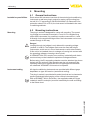
Each series 600 instrument consists of the actual signal conditioning
instrument as well as a plug-in socket for carrier rail mounting (tophat rail 35 x 7.5 according to DIN EN 50022/60715). Because it has
protection class IP 30 or IP 20, the instrument is intended to be used
in switching cabinets.
The plug-in socket is designed for carrier rail mounting. The operating voltage is connected to terminals 17 and 18. For neighbouring
series 600 instruments it is possible to continue connection L1 and
Ndirectlyviathesuppliedbridges.Max.fiveinstrumentscanbeconnected through in this way.
Danger:
Looping through via bridges is only allowed for operating voltage
(sockets L1 and N). The bridges must never be used with single
instruments, at the end of a row of instruments or with other sockets.
If this rule is not heeded, there is a danger of coming into contact with
the operating voltage or causing a short circuit.
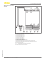
A VEGAMET 624 in Ex version is an auxiliary, intrinsically safe instrument and may not be installed in explosion-endangered areas.
Before setup, the Ex separating chamber must be attached (as shown
below) with Ex versions. Safe operation can be only ensured if the
operatinginstructionsmanualandtheEGtypeapprovalcertificate
are observed. VEGAMET 624 must not be opened.
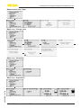
Instrument coding
Allsignalconditioninginstrumentsareprovidedwithdifferentgaps
dependent on type and version (mechanical coding).
The plug-in socket is provided with coded pins that can be inserted to
prevent accidental interchanging of the various instrument types.
With a VEGAMET 624 in Ex version, the supplied coded pins (type
coded pin and Ex coded pin) must be inserted by the user according
to the below chart.
28969-EN-130701
10
VEGAMET 624 • 4 … 20 mA/HART
4 Mounting
1
1
2
3
Ao
Bo
Co
1o
2o
3o
o
o
o
4
7o
8o
9o
o
o
12 o
4
VEGA
N
L1
5
6
7
Ao
Bo
Co
1o
2o
3o
4o
5o
6o
7o
8o
9o
10 o
11 o
12 o
8
VEGA
2
3
N
L1
4
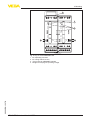
Fig. 2: Plug-in socket VEGAMET 624
Ex separating chamber
Ex coding with Ex version
Type coding for VEGAMET 624/625
Bridges for looping the operating voltage
28969-EN-130701
1
2
3
4
VEGAMET 624 • 4 … 20 mA/HART
11
5 Connecting to power supply
5
Note safety instructions
Connecting to power supply
5.1
Preparing the connection
Always keep in mind the following safety instructions:
•
•
Connect only in the complete absence of line voltage
If overvoltage surges are expected, overvoltage arresters should
be installed
Take note of safety
instructions for Ex
applications
Inhazardousareasyoumusttakenoteoftherespectiveregulations,
conformityandtypeapprovalcertificatesofthesensorsandpower
supply units.
Select power supply
Thevoltagesupplycanbe20…253VAC/DC,50/60Hz.
Select connection cable
The operating voltage of VEGAMET 624 is connected with standard
cable according to the national installation standards.
Standard two-wire cable can be used for connecting the sensors. The
screening is absolutely necessary to ensure interference-free operation with HART sensors.
Cable screening and
grounding
Connect the cable screen on both ends to ground potential. In the
sensor, the screen must be connected directly to the internal ground
terminal. The ground terminal on the outside of the sensor housing
must be connected to the potential equalisation (low impedance).
If potential equalisation currents are expected, the screen connection
on the side of VEGAMET 624 must be made via a ceramic capacitor
(e. g. 1 nF, 1500 V). The low frequency potential equalisation currents
arethussuppressed,buttheprotectiveeffectagainsthighfrequency
interference signals remains.
Select connection
cable for Ex applications
Take note of the corresponding installation regulations for Ex applications. In particular, make sure that no potential equalisation currents
flowoverthecablescreen.Incaseofgroundingonbothsidesthis
can be achieved by the use of a capacitor or a separate potential
equalisation.
5.2
Connection procedure
Move on to electrical connection and proceed as follows:
1. Snap the socket without VEGAMET 624 onto the carrier rail
2. Connect sensor cable to terminal 1/2 (active input) or 3/4 (passive
input), provide a screening
3. When using several sockets, loop the power supply by means of
bridges
4. Connectpowersupply(switchedoff)toterminal17and18
6. Insert VEGAMET 624 into the plug-in socket and screw it down
tightly
Theelectricalconnectionishencefinished.
12
VEGAMET 624 • 4 … 20 mA/HART
28969-EN-130701
5. If necessary, connect relays or other outputs
5 Connecting to power supply
Before setting up Ex versions, make sure the Ex separating chamber
is plugged on the left housing side (above the sensor terminals). The
pins for type and Ex coding must also be inserted correctly.
28969-EN-130701
Information:
• On the active input (terminal 1/2), VEGAMET 624 provides power
for the connected sensors. Power supply and measurement data
are transmitted over the same two-wire cable. This mode is provided for connection of measuring transducers without separate
operating voltage (sensors in two-wire version).
• On the passive input (terminals 3/4), the sensors are not supplied
with energy - only the measured value is transmitted. This input is
for instruments with their own separate operating voltage (sensors
in four-wire version or separators such as VEGATRENN 149). On
a VEGAMET 624 in Ex version, the passive input is not available
due to approval/technical reasons.
VEGAMET 624 • 4 … 20 mA/HART
13
5 Connecting to power supply
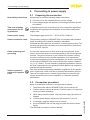
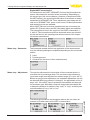
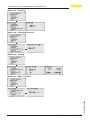
Wiring plan for two-wire
sensor
5.3
Wiring plan
10
+ -
+ -
1
3
2
8
4
6
7
8
9
4
9 10
5
5
6
+ -
+ -
+ -
11 12
13 14
15 16
17 18 19 20 21 22
23 24 25 26 27 28
+ -
11
L1 N
7
1
2
3
Fig. 3: Wiring plan VEGAMET 624 with two-wire sensor
1
2
3
4
5
6
7
8
9
10
11
Internal operating relay 1
Internal operating relay 2
Internal operating relay 3
Internal current output 1
Internal current output 2
Internal current output 3
Voltage supply of VEGAMET 624
Measurement data input with sensor supply (active input)
Measurement data input (passive input), not with Ex-ia version
Internal fail safe relay
4 … 20 mA/HART sensor (two-wire version)
28969-EN-130701
14
VEGAMET 624 • 4 … 20 mA/HART
5 Connecting to power supply
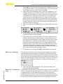
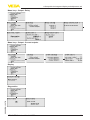
Wiring plan for four-wire
sensors
10
+ -
+ -
1
3
2
8
4
6
7
8
9
4
9 10
5
5
6
+ -
+ -
+ -
11 12
13 14
15 16
17 18 19 20 21 22
23 24 25 26 27 28
+ -
11
L1 N
12
7
1
2
3
Fig. 4: Wiring plan VEGAMET 624 with four-wire sensors
Internal operating relay 1
Internal operating relay 2
Internal operating relay 3
Internal current output 1
Internal current output 2
Internal current output 3
Voltage supply of VEGAMET 624
Measurement data input with sensor supply (active input)
Measurement data input (passive input), not with Ex-ia version
Internal fail safe relay
4 … 20 mA/HART sensor (four-wire version)
Power supply for four-wire sensor
28969-EN-130701
1
2
3
4
5
6
7
8
9
10
11
12
VEGAMET 624 • 4 … 20 mA/HART
15
6 Setup with the integrated display and adjustment unit
6
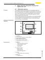
Function
Display and adjustment
elements
Setup with the integrated display and
adjustment unit
6.1
Adjustment system
The integrated display and adjustment unit is used for measured
value display, adjustment and diagnosis of VEGAMET 624 as well as
the connected sensors. The indication and adjustment are carried out
via four keys and a clear, graphic-capable display with background
lighting. The adjustment menu with selectable language is clearly
structured and enables easy setup.
Certain adjustment options are not possible or only partially available
with the integrated display and adjustment unit, e.g. settings for the
e-mail server. For such applications, the use of PACTware with appropriate DTMs is recommended.
7
1
1
2
6
3
COM
5
4
ESC
OK
2
3
on
Ser. No.
12345678
Fig. 5: Display and adjustment elements
Key functions
1
2
3
4
5
6
7
LC display
Adjustment keys
Communication interface for VEGACONNECT
Status indication operation
Status indication fail safe relay
Status indication interface activity
Status indication operating relay 1 - 3
•
[OK] key:
– Move to the menu overview
– Confirmselectedmenu
– Edit parameter
– Save value
•
•
16
[+] key:
– Change value of the parameter
[ESC] key:
– Interrupt input
VEGAMET 624 • 4 … 20 mA/HART
28969-EN-130701
•
[->] key to select:
– Menu change
– Select list entry
– Select editing position
6 Setup with the integrated display and adjustment unit
– Jump to next higher menu
Note:
Approx. 10 minutes after the last pressing of a key, an automatic reset
tomeasuredvalueindicationistriggered.Anyvaluesnotconfirmed
with [OK] will not be saved.
Parameter adjustment
6.2
Setup steps
Through parameter adjustment, the instrument is adapted to the individual application conditions. A measurement loop calibration is the
most important step and should always be carried out. A scaling of
the measured value to the desired physical variable and unit, possibly
includingalinearizationcurve,isoftenuseful.Theadaptationofthe
relay switching points or the setting of an integration time to smooth
the measured value are further standard adjustment options.
Instruments with Ethernet interface can be provided with a Host name
suitable for the measurement loop. As an alternative to the addressing
via DHCP, it is also possible to adjust an IP address and subnet mask
suitable for your network. If necessary, the e-mail/Web server can be
alsoconfiguredwithPACTware.
Information:
When using PACTware and the corresponding VEGA DTM, additional
settings can be carried out which are not possible or only partly possible with the integrated display and adjustment unit. When using an
adjustment software, you either need one of the integrated interfaces
(RS232/Ethernet) or the interface converter VEGACONNECT.
Further instructions for setting up the web server and e-mail functions
are stated in the online help of PACTware or the VEGAMET 624 DTMs
aswellasthesupplementaryinstructionsmanual"RS232/Ethernet
connection".
Switch-on phase
Afterbeingswitchedon,VEGAMET624firstofallcarriesoutashort
self-check. The following steps are carried out:
•
•
•
Internal check of the electronics
indicationoftheinstrumenttype,firmwareversionaswellasthe
instrument TAG (instrument name)
Theoutputsignalsjumpbrieflytothesetfaultvalue
Then the current measured values will be displayed and outputted.
28969-EN-130701
Measured value indication
The measured value indication displays the digital indication value,
the measurement loop name (measurement loop TAG) and the unit.
An analogue bar graph can also be displayed. By pushing the [>] key,
you move between the individual display options.
→ By pushing [OK] you move from the measured value indication to
the main menu.
VEGAMET 624 • 4 … 20 mA/HART
17
6 Setup with the integrated display and adjustment unit
Main menu
The main menu is divided into six areas with the following functions:
•
•
•
•
•
•
Device settings: Includes the device-TAG, settings for network
connection such as date/time setting, …
Measurement loop: Includes settings for input selection, adjustment,damping,linearization,scaling,outputs,…
Display: Includes settings to the displayed measured value
Diagnosis Includes information to the device status, error messages, input current
Service Includes simulation, reset, PIN, selectable language,
sensor address, …
Info: Shows serial number, software version, last change, instrument features, MAC addr., …
→ Selectthemenuitem"Device settings"with[->]andconfirmwith
[OK].
Device settings - DeviceTAG
You can assign an unambiguous name to VEGAMET 624 via the
Device-TAG. This function is recommended when several instruments
are implemented and a good documentation of larger systems is
required.
→ Enter the requested values via the appropriate keys and save
Device settings - Host
Name/IP addr.
your settings with [OK].
For instruments with integrated Ethernet interface, the automatic
addressing via DHCP is preset, i.e. the IP address must be assigned
by a DHCP server. Generally the instrument is contacted via the Host
name. By default, the host name consists of the serial number plus
"VEGA-"infront.Asanalternative,itisalsopossibletoenterastatic
IP addr. with Subnet mask and optional Gateway addr.
Note:
Keepinmindthatyourmodificationwillbeonlyeffectiveafterarestart
ofVEGAMET624.Youcanfindfurtherinformationofthesenetwork
parametersinthesupplementaryinstructions"RS232/Ethernet connection"andintheOnlinehelpoftherespectiveDTM.
18
VEGAMET 624 • 4 … 20 mA/HART
28969-EN-130701
Carry out your settings via the appropriate keys and save with [OK].
6 Setup with the integrated display and adjustment unit
→ Carry out your settings via the appropriate keys and save with
[OK].Disconnectbrieflytheoperatingvoltagesothatthemodifiedsettingsbecomeeffective.
Device settings - Time/
Date
Date and time can be entered in this menu item for instruments with
integratedRS232/Ethernetinterface.Thesetimesettingsarebuffered
in case of power failure for approx. 3 days.
→ Enter the values via the appropriate keys and save your settings
with [OK].
Device settings - Commu- For instruments with integrated RS232 interface, you determine here
nication protocol
which mode this serial interface should operate in. The following options are available:
•
•
•
VVO protocol: Direct standard connection between signal conditioning instrument and PC for parameter adjustment and enquiry
(e.g. with PACTware and DTM)
PPP: Dial-up connection between signal conditioning instrument
and modem for independent transmission of e-mails (dial-out connection) or enquiry via web browser (dial-in connection)
ASCII protocol: Direct standard connection between signal conditioning instrument and PC for enquiry with terminal programs,
e.g. Hyperterminal
→ Carry out your settings via the respective keys and save with
[OK]. Further information is available in the supplementary
instructionsmanual"RS232/Ethernet connection"andtheonline
help of the respective DTM.
28969-EN-130701
Measurement loop - Input The VEGAMET 624 can process measured values from 4 … 20 mA/
HART sensors via analogue communication as well as via digital
HART protocol.
Analogue 4 … 20 mA transmission
In the standard setting of VEGAMET 624 the measured value transmission is carried out via analogue 4 … 20 signal. An adjustment in
thesensorinfluencesdirectlytheinputvariableofVEGAMET624.
Only carry out the adjustment on one instrument, either on VEGAMET
624 or on the sensor. The adjustment in VEGAMET 624 is always carried out in mA (analogue transmission).
VEGAMET 624 • 4 … 20 mA/HART
19
6 Setup with the integrated display and adjustment unit
Digital HART transmission
For transmission via HART, VEGAMET 624 must be informed which
sensor value should be used for further processing. Depending on
the sensor type, this can be distance, pressure or temperature. With
all HART sensors, the unchanged initial value of the sensor is always
transmitted to VEGAMET 624. Thus, adjustment must always be carriedoutonVEGAMET624,neveronthesensor.Differentparameters
and measuring units are available.
When HART sensors from other manufacturers are connected, the
options PV (Primary Value) and SV (Secondary Value) are available.
The prerequisite for this is the support of the HART commands 0, 1,
3, and 15. This information and which measured values are transmitted can be found in the operating instructions manual of the respective sensor manufacturer.
Meas. loop - Parameter
Themeasuredvariabledefinestheapplicatonofthemeasurement
loop, the following settings are available depending on the connected
sensor:
•
•
•
Meas. loop - Adjustment
Level
Process pressure
Universal (for sensors of other manufacturers)
Through the adjustment the input value of the connected sensor is
converted into a percentage value. This conversion step allows any
input value range to be depicted in a relative range (0 % up to 100 %).
Before carrying out the adjustment, the requested adjustment unit can
beselected.Withinputselection"Analogue",theadjustmentunitisalways"mA".IftheHARTinputisactivated,theavailableunitdepends
on the sensor type. With radar, ultrasonic and guided microwave this
isalwaysthedistanceinmetresorfeet"m(d)"or"ft(d)",andwithpressuretransmittersitise.g."bar"or"psi".
20
VEGAMET 624 • 4 … 20 mA/HART
28969-EN-130701
The following illustrations and examples relate to the min./max. adjustment of a radar sensor with HART communication.
6 Setup with the integrated display and adjustment unit
1. With [OK] you prepare the percentage value for editing, with [->]
you place the cursor to the requested position. Set the requested
percentage value with [+] and save with [OK].
2. After entering the percentage value for the min. adjustment, the
suitable distance value must be entered. If you want the use the
currentlymeasureddistancevalue,selectthemenuitem"Accept"
(live adjustment or adjustment with medium). If the adjustment
should be carried out independent of the measured level, then
selecttheoption"Edit".Enternowthedistancevalueinm[m(d)]
for the empty vessel that is suitable for the percentage value, e.g.
distance from the sensor to the vessel bottom (dry adjustment or
adjustment without medium).
3. Save your settings with [OK]andmoveto"Max.adjustment"with
[->].
4. As described previously, enter now the percentage value for max.
adjustmentandconfirmwith[OK].
5. After entering the percentage value for the max. adjustment, the
suitable distance value must be entered. If you want the use the
currentlymeasureddistancevalue,selectthemenuitem"Accept"
(live adjustment or adjustment with medium). If the adjustment
should be carried out independent of the measured level, then
selecttheoption"Edit".Enternowthedistancevalueinm[m(d)]
for the full vessel that is suitable for the percentage value (dry
adjustment or adjustment without medium). Keep in mind that the
max. level must be below the radar antenna.
6. Finally save your settings with [OK],theadjustmentisfinished.
Meas. loop - Damping
Tosuppressfluctuationsinthemeasuredvaluedisplay,e.g.caused
by an agitated product surface, an integration time can be set. This
time can be between 0 and 999 seconds. Remember that the reaction
time of the entire measurement will then be longer and the sensor will
react to measured value changes with a delay. In general, a period of
afewsecondsissufficienttosmooththemeasuredvaluedisplay.
→ Enter the requested parameters via the appropriate keys and
28969-EN-130701
save your settings with [OK].
Meas. loop - Linearization Alinearizationisnecessaryforallvesselsinwhichthevesselvolume
curve
does not increase linearly with the level, for example, with a cylindrical
orsphericaltank.Correspondinglinearizationcurvesarepreprogrammed for these vessels. They represent the correlation between
the level percentage and vessel volume. By activating the appropriate
curve, the volume percentage of the vessel is displayed correctly. If
VEGAMET 624 • 4 … 20 mA/HART
21
6 Setup with the integrated display and adjustment unit
the volume should not be displayed in percent but e.g. in l or kg, a
scaling can be also set.
→ Enter the requested parameters via the appropriate keys and
save your settings with [OK].
Meas. loop - Scaling
Scaling means converting the measured value into a certain parameterandunit.Thelinearizedpercentagevalueisthesourcesignal
which is used as basis for the scaling. The indication can then show
the volume in litres e.g., instead of the percentage value. Indication
values from max. -99999 to +99999 are possible.
→ Enter the requested parameters via the appropriate keys and
save your settings with [OK].
Meas. loop - Meas. loop
TAG
In this menu item you can enter an unambiguous designation for each
measurement loop, e.g. the measurement loop name or the tank or
product designation. In digital systems and in the documentation
of larger plants, a singular designation should be entered for exact
identificationofindividualmeasuringpoints.
→ Enter the requested parameters via the appropriate keys and
save your settings with [OK].
Meas. loop - Outputs Relays outputs
Under"Outputs"youwillfindtherelay/currentoutputs.Withrelay
output,firstofalltherequestedmode("Overfill protection"or"Dry
running protection")mustbeselected.
•
•
Overfillprotection:Relayisswitchedoffwhenthemax.levelis
exceeded (safe currentless condition), relay is switched on again
when the level falls below the min. level (switch-on point < switchoffpoint)
Dry run protection:Relayisswitchedoffwhenthelevelfalls
below the min. level (safe currentless condition), relay is switched
on again when the max. level is exceeded (switch-on point >
switch-offpoint)
22
VEGAMET 624 • 4 … 20 mA/HART
28969-EN-130701
Additionalmodessuchas"Switching window","Flow"and"Tendency"canbeonlyadjustedviaPACTwareandDTM.
6 Setup with the integrated display and adjustment unit
Select the requested mode and save with [OK]. By pushing [->], you
reach the next menu item.
1. Now enter the reference value to which the relay switching points
relate. By pushing [->], you reach the next menu item.
2. Enternowtheswitchingpointsforswitchingtherelayonandoff.
The parameter to which they refer can also be selected.
In the following window the reaction of the relay in case of failure can
bedetermined.Hereyoucandefinewhether,incaseoffailure,the
switching condition of the relay remains unchanged or the relay is
switchedoff.
Meas. loop - Outputs Current outputs
The current output is used to transfer the measured value to a higher
ranking system, for example to a PLC, a control system or a measured value indication. This is an active output, i.e. a current is provided
actively. The processing unit must hence have a passive current input.
28969-EN-130701
The characteristics of the current outputs can be set to 0 … 20 mA,
4 … 20 mA or inverted. The reaction in case of failure can be also
adapted to the requirements. The parameter to which they refer can
also be selected.
→ Enter the requested parameters via the appropriate keys and
save your settings with [OK].
Display
Inthemenuitem"Display - Indication value",youcansettherequested indication value. The following options are available:
VEGAMET 624 • 4 … 20 mA/HART
23
6 Setup with the integrated display and adjustment unit
•
•
•
•
Percent: adjusted measured value without taking a probably
storedlinearizationintoaccount
Lin. percent: adjusted measured value by taking a probably
storedlinearizationintoaccount
Scaled: adjusted measured value by taking a probably stored
linarizationintoaccountaswellasthevaluesenteredunder"Scaling"
Sensor value: input value delivered by the sensor. Presentation in
the selected adjustment unit
→ Enter the requested parameters via the appropriate keys and
save your settings with [OK].
Diagnostics
When the instrument displays a failure message, further information is
availableunderthemenuitem"Diagnosis - Device status".
Service - Simulation
The simulation of a measured value is used to check the outputs and
connected components. The simulation can be applied to the percentage value, the lin. percentage value and the sensor value.
Note:
Please note that connected system parts (valves, pumps, motors,
controlsystems)areinfluencedbythesimulation,thusunintentional
plant operating conditions can occur. The simulation is terminated
automatically after approxminately 10 minutes.
→ Carry out your settings via the appropriate keys and save with
[OK].
A reset to default changes all settings (with only a few exceptions)
back to factory default. Exceptions are: Host name, IP-address, subnet mask, time, language.
Service - Display language
Inthemenuitem"Display - Language",therequesteddisplaylanguage can be adjusted. The following languages are available:
24
•
German
VEGAMET 624 • 4 … 20 mA/HART
28969-EN-130701
Service - Reset
6 Setup with the integrated display and adjustment unit
•
•
•
•
•
•
English
French
Spanish
Russian
Italian
Dutch
→ Carry out your settings via the appropriate keys and save with
[OK].
Service - PIN
The signal conditioning instrument can be locked with a PIN to protect
thesetparametersagainstunauthorizedmodification.Afteractivation, it is not possible to carry out a parameter adjustment via the
built-in display and adjustment unit without entering the previously
specifiedPIN.Thislockingdoesnotapplytoparameteradjustment
with PACTware and the respective DTM.
Service - Sensor address
With every 4 … 20 mA/HART sensor, the measured value can be
transmitted via analog current signal or digital HART signal. This is
regulated via the HART mode or the address. If a HART sensor is set
to address 0, the sensor is in the standard mode. Here the measured
value is transmitted digitally on the 4 … 20 mA cable.
In mode HART Multidrop, an address from 1 … 15 is assigned to the
sensor.Bydoingso,thecurrentisfixlimitedto4mAandthemeasured value transmission is only made digitally.
28969-EN-130701
Firstofall,enterthepreviousaddressofthesensortobemodified
(factory setting 0), then you can assign the requested HART address
intherangeof01-15inthemenu"New address".
Service - Data transmission
With instrument versions with integrated RS232/Ethernet interface,
a manual data transmission to a WEB-VV server can be trigger, for
example, for test purposes. Requirement is that a WEB-VV event was
configuredinadvanceviaPACTware/DTM.
Info
Inthemenuitem"Info"thefollowinginformationisavailable:
VEGAMET 624 • 4 … 20 mA/HART
25
6 Setup with the integrated display and adjustment unit
•
•
•
•
•
Optional settings
Sensor type and serial number
Date of manufacture and software version
Date of last change using PC
Instrument features
MAC address (with interface option Ethernet)
Additional adjustment and diagnostics options are available via the
Windows software PACTware and the suitable DTM. Connection can
be made optionally via the built-in standard interface or one of the
optionallyofferedinterfaces(RS232/Ethernet).Furtherinformation
isavailableinchapter"Parameter adjustment with PACTware",in
the online help of PACTware or the DTM as well as in the operating
instructionsmanual"RS232/Ethernet connection".Anoverviewof
the standard functions and their adjustment options can be found in
chapter"Functional overview"inthe"Supplement".
6.3
Menu schematic
Information:
Depending on the instrument version and application, the highlighted
menu windows are not always available.
Measured value indication
Device settings
28969-EN-130701
26
VEGAMET 624 • 4 … 20 mA/HART
6 Setup with the integrated display and adjustment unit
Measurement loop - Input
Meas. loop - Change input
Meas. loop - Parameter
28969-EN-130701
Meas. loop - Adjustment
VEGAMET 624 • 4 … 20 mA/HART
27
6 Setup with the integrated display and adjustment unit
Meas. loop - Damping
Meas. loop - Linearization curve
Meas. loop - Scaling
Meas. loop - Meas. loop TAG
28969-EN-130701
28
VEGAMET 624 • 4 … 20 mA/HART
6 Setup with the integrated display and adjustment unit
Meas. loop - Output - Relay
Meas. loop - Output - Current outputs
Display
28969-EN-130701
Diagnostics
VEGAMET 624 • 4 … 20 mA/HART
29
6 Setup with the integrated display and adjustment unit
Service
Service - Simulation
Service - Sensor address
Service - Data transmission (only with option RS232/Ethernet interface)
28969-EN-130701
30
VEGAMET 624 • 4 … 20 mA/HART
6 Setup with the integrated display and adjustment unit
28969-EN-130701
Info
VEGAMET 624 • 4 … 20 mA/HART
31
7 Setup with PACTware
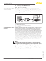
7
7.1
Connect the PC
For a brief connection of the PC, e.g. for parameter adjustment,
connection can be carried out via the VEGACONNECT 4 interface
converter. The necessary I²C interface on the front is available on all
instrument versions. On the computer side, connection is carried out
via the USB interface.
EN
OP
USB
TWIST
LO
CK
Connection of the PC via
VEGACONNECT
Setup with PACTware
3
1
2
Fig. 6: Connection via VEGACONNECT
1
2
3
Connection of the PC via
Ethernet
USB interface of the PC
I²C connection cable of VEGACONNECT 4
I²C interface
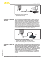
With the Ethernet interface, the instrument can be connected directly
to an existing PC network. Any standard patch cable can be used.
A cross-over cable must be used when connecting the instrument
directly to the PC. To reduce EMC interferences, the supplied split ferrite should be connected to the Ethernet cable. Each instrument can
then be accessed from anywhere in the network by an unique Host
name or its own IP address. The parameter adjustment of the instrument via PACTware and DTM can be carried out from any PC. The
measured values can be made available to individual users within the
company network as HTML chart. As an alternative, the independent,
time or event-controlled transmission of measured values via e-mail
is also possible. The measured values can also be called up via a
visualisation software.
Note:
To respond the instrument, the IP address or the Host name must
beknown.Youcanfindthisinformationunderthemenuitem"Device
settings".Ifyouaremodifyingthesespecifications,theinstrument
must be restarted afterwards. Then the instruments can be reached
from everywhere in the network via its IP address or the Host name.
ThesespecificationsmustbealsoenteredintheDTM(seechapter
"Parameter adjustment with PACTware").
28969-EN-130701
32
VEGAMET 624 • 4 … 20 mA/HART
7 Setup with PACTware
2
3
1
Fig. 7: Connection of the PC via Ethernet
1
2
3
Ethernet interface of the PC
Ethernet connection cable (Cross-Over cable)
Ethernet interface
Connection of the modem The RS232 interface is particularly suitable for simple modem convia RS232
nection. External analog, ISDN and GSM modems with standard
interface can be used. The necessary RS232 modem connection
cable is included with the delivery. To reduce EMC interference, you
should mount the supplied ferrite bead on the RS232 modem connection cable. Via a visualisation software, measured values can be
retrieved remotely and further processed. Alternatively, autonomous
time or event controlled transmission of measured values via e-mail
is also possible. Remote parameter adjustment of the instrument and
the connected sensors is also possible with PACTware.
3
1
2
Fig. 8: Connection of the modem via RS232
1
2
3
28969-EN-130701
Connection of the PC via
RS232
Analogue, ISDN or GSM modem with RS232 interface
RS232 modem connection cable (in the scope of delivery)
RS232 interface (RJ45 plug connection)
Via the RS232 interface, direct parameter adjustment and measured
value retrieval from the instrument can be carried out with PACTware.
Use the RS232 modem connection cable supplied with the instrument and an additionally connected null modem cable (e.g. article no.
LOG571.17347). To reduce EMC interference, you should mount the
supplied ferrite bead on the RS232 modem connection cable.
If there is no RS232 interface available on the PC or if it is already
occupied, you can also use a USB-RS232 adapter (e.g. article no.
2.26900).
VEGAMET 624 • 4 … 20 mA/HART
33
7 Setup with PACTware
4
3
1
2
Fig. 9: Connection of the PC via RS232
1
2
3
4
RS232 interface of the PC
RS232 interlink cable (article no. LOG571.17347)
RS232 modem connection cable (in the scope of delivery)
RS232 interface (RJ45 plug connection)
Assignment RS232 modem connection cable
1
1
8
2
3
5 4 3 2 1
9 8 7 6
RXD
4
2
TXD
3
3
RTS
6
7
CTS
2
8
GND
5
5
DTR
1
4
Fig. 10: Terminal assignment of the RS232 modem connection cable
1
2
3
Prerequisites
Name of the interface cable
Assignment of the RJ45 plug (view contact side)
Assignment of the RS232 plug (view soldering side)
7.2
Parameter adjustment with PACTware
Note:
To ensure that all instrument functions are supported, you should
always use the latest DTM Collection. Furthermore, not all described
functionsareincludedinolderfirmwareversions.Youcandownload
34
VEGAMET 624 • 4 … 20 mA/HART
28969-EN-130701
As an alternative to the integrated display and adjustment unit, the
adjustment can be also carried out via a Windows PC. For this, the
configurationsoftwarePACTwareandasuitableinstrumentdriver
(DTM) according to the FDT standard are required. The current PACTware version as well as all available DTMs are compiled in a DTM
Collection. Furthermore, the DTMs can be integrated into other frame
applications compliant with the FDT standard.
7 Setup with PACTware
the latest instrument software from our homepage. A description of
the update procedure is also available in the Internet.
Further setup steps are described in the operating instructions
manual"DTM Collection/PACTware"attachedtoeachDTMCollection and which can also be downloaded from the Internet. A detailed
description is available in the online help of PACTware and the DTMs
aswellasinthesupplementaryinstructionsmanual"RS232/Ethernet
connection".
Connection via Ethernet
To respond the instrument, the IP address or the Host name must be
known.Youcanfindthisinformationunderthemenuitem"Device
settings".Iftheprojectsetupiscarriedoutwithoutassistant(offline
mode), IP address and subnet mask or the Host name must be
entered in the DTM. Click in the project window with the right mouse
keyontheEthernetDTMandchoose"Add. functions - Modify DTM
addresses".
Standard/Full version
All device DTMs are available as a free-of-charge standard version
and as a full version that must be purchased. In the standard version,
all functions for complete setup are already included. An assistant for
simpleprojectconfigurationsimplifiestheadjustmentconsiderably.
Saving/printing the project as well as import/export functions are also
part of the standard version.
In the full version there is also an extended print function for complete
project documentation as well as a save function for measured value
and echo curves. In addition, there is a tank calculation program as
well as a multiviewer for display and analysis of the saved measured
value and echo curves.
7.3
Setup web server/e-mail, remote enquiry
Setup and application examples of the web server, the e-mail functionsandthevisualisationWEB-VVarespecifiedinthesupplementaryinstructions"RS232/Ethernet connection".
The connection via Modbus-TCP or ASCII protocol is described in the
supplementaryinstructionmanual"Modbus-TCP, ASCII protocol".
28969-EN-130701
Both supplementary instruction manuals are included with every
instrument with RS232 or Ethernet interface.
VEGAMET 624 • 4 … 20 mA/HART
35
8 Application examples
8
Application examples
8.1
Functional principle
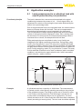
Level measurement in a cylindrical tank with
overfillprotection/dryrunprotection
The level is detected via a sensors and transmitted to the signal
conditioning instrument by means of a 4 … 20 mA signal. Here, an
adjustment is carried out converting the input value delivered by the
sensor into a percentage value.
Due to the geometrical form of the cylindrical tank, the vessel volume
does not increase linear with the level. This can be compensated
byselectingthelinearizationcurveintegratedintheinstrument.
This curve states the relation between percentage level and vessel
volume. If the level should be displayed in litres, also a scaling must
becarriedout.Forthispurpose,thelinearizedpercentagevalueis
converted into a volume, for example with the unit litres.
Filling and emptying are controlled via relay 1 and 2 which are
integratedinthesignalconditioninginstrument.Duringfilling,relay
mode"Overfill protection"isset.Therelayisthusswitchedoff(safe
currentless condition) when the max. level is exceeded, and switched
onagainwhenthemin.levelisunderrun(switch-onpoint<switch-off
point).Duringemptying,mode"Dry run protection"isused.Thisrelay
isthusswitchedoffwhenthemin.levelisunderrun(safecurrentless
condition), and switched on again when the min. level is exceeded
(switch-onpoint>switch-offpoint).
Rel. 1
Rel. 2
100%
Rel. 1: 90%
Rel. 2: 5%
0%
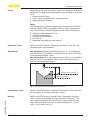
Fig. 11: Example for a level measurement, cylindrical tank
Example
VEGAMET 624 • 4 … 20 mA/HART
28969-EN-130701
36
A cylindrical tank has a capacity of 10000 litres. The measurement
is carried out with a level sensor operating according to the principle
oftheguidedmicrowave.Thefillingbyatankcariscontrollviarelay
1andavalve(overfillprotection).Thedischargeiscarriedoutvia
a pump and is controlled by relay 2 (dry run protection). The max.
volume should be at 90 % level, these are 9538 litres with a standard
vessel (according to bearing chart). The min. level should be adjusted
8 Application examples
to 5 %, this corresponds to 181 litres. The volume should be displayed
in litres.
Adjustment
Carry out the adjustment in the signal conditioning instrument as
describedinchapter"Setup steps".Noadditionaladjustmentmust
hencebecarriedoutonthesensors.Forthemax.adjustment,fillthe
vessel up to the requested max. level and accept the actually measured value. If this is not possible, the respective current value can be
entered alternatively. For the min. adjustment, empty the vessel up to
the min. level or enter the respective current value.
Linearization
Todisplaythepercentagelevelcorrectly,selectunder"Measurement
loop - Linearization curve"theentry"Cylindrical tank".
Scaling
Todisplaythevolumeinlitres,youhavetoenter"Volume"asunitin
litresunder"Measurement loop - Scaling".Theallocationisthencarried out, in this example 100 % ≙ 10000 litres and 0 % ≙ 0 litres.
Relay
Percent is selected as reference value for the relays. The mode of relay1issettooverfillprotection,relay2getsmodedryrunprotection.
Toensurethatthepumpswitchesoffincaseoffailure,thereaction
in case of failure should be adjusted to switching status OFF. The
switching points are adjusted as follows:
•
•
Relay 1:Switch-offpoint90%,switch-onpoint85%
Relay 2: Switch-offpoint5%,switch-onpoint10%
Information:
Theswitchonandoffpointoftherelaysmustnotbeadjustedtothe
same switching point because this would cause a permanent switchin
onandoffwhenthisthresholdisreached.Toavoidthiseffectalso
withfluctuatingproductsurface,adifference(hysteresis)of5%is
useful between the switching points.
8.2
28969-EN-130701
Functional principle
Pump control 1/2 (running time controlled)
Pump control 1/2 is used to control several pumps with the same
function dependent on the previous running time. Always the pump
with the shortest running time is switched on and the pump with
thelongestrunningtimeswitchedoff.Withincreasedrequirement,
all pumps can also run at the same time dependent on the entered
switchingpoints.Withthismeasure,asteadyutilizationofthepumps
is achieved and the reliability increased.
All relays with activated pump control are not assigned to a certain
switchingpointbutareswitchedonoroffdependingontheaccumulated operating time. The signal conditioning instrument selects
the relay with the shortest operating time when the switch-on point
is reached and the relay with the longest operating time when the
switch-offpointisreached.
Withthispumpcontrol,therearetwodifferentversions:
VEGAMET 624 • 4 … 20 mA/HART
37
8 Application examples
•
•
Pump control 1: The upper switching point determines the switchoffpointfortherelay,whereasthelowerswitchingpointdetermines the switch-on point
Pump control 2: The upper switching point determines the switchon point for the relay, whereas the lower switching point determinestheswitch-offpoint
Example
Two pumps should empty the vessel when a certain level is reached.
At80%filling,thepumpwiththeshortestrunningtimeshouldswitch
on. If the level nevertheless increases, a second pump should switch
onat90%.Bothpumpsshouldswitchoffagainat10%filling.
Setup
SelectintheDTMnavigationsectionthemenuitems"Meas. loop Outputs - Relay".
•
•
Setmode"Pump control 2"forrelay1and2.
Entertheswitchingpointsfortheaffectedrelaysasfollows:
– Relay 1 upper switching point = 80.0 %
– Relay 1 lower switching point = 10.0 %
– Relay 2 upper switching point = 90.0 %
– Relay 2 lower switching point = 10.0 %
The function of pump control 2 is shown in detail in the following diagram. The previously described example is used as a basis.
Rel. 2: 90% On
Rel. 1: 80% On
Rel. 1, 2: 10% Off
Rel. 1
Rel. 2
On
Off
On
Off
10
30
20
20
5
15
t [h]
Fig. 12: Example of pump control 2
Switch on reaction of the pump control 2
When the signal conditioning instrument is switched on, the relays are
atfirstinaswitched-offstatus.Dependingontheinputsignalandthe
switched-on period of the individual relays, the following relay switching conditions can occur after the start procedure:
•
•
38
Input signal is higher than the upper switching point -> Relay with
the shortest switch on period is switched on
Input signal is between lower and upper switching point -> Relay
remainsswitchedoff
Input signal is smaller than the lower switching point -> Relay
remainsswitchedoff
VEGAMET 624 • 4 … 20 mA/HART
28969-EN-130701
•
8 Application examples
Option forced changeover
When the level was not changed for a longer period, always the same
pumpwouldhavebeenswitchedon.Viatheparameter"Changeover
time",atimecanbepresetafterwhichaforcedchangeoverofthe
pump is carried out. Which pump will be switched on depends ont he
selected pump mode. If all pumps are already switched on, then the
pump still remains switched on. These function can be only adjusted
via PC and DTM.
Note:
If the pump is already switched on when activating the forced
changeover,thetimerwillnotbestarted.Onlyafterswitchingoffand
onagain,willthetimerstart.Iftheswitch-offdelayisset,itwillnot
be taken into account, i.e. the changeover is carried out exactly after
the preset time for the forced changeover expires. A preset switch-on
delay, however, is taken into account, i.e. the forced changeover to
another pump is carried out after the preset time expires. Before the
newly selected pump switches on, the preset switch-on delay for this
pump must be expired.
8.3
Functional principle
Thefunctionofthetendencyrecognitionistorecognizeadefined
change within a certain time period and to transfer this information to
a relay output.
Principle of operation
The information for tendency recognition is generated out of the
measured value change per time unit. The output variable is always
themeasuredvalueinpercent.Thefunctioncanbeconfiguredfor
rising and falling tendency. The actual measured value is determined
and summed with a sample rate of a second. After the max. reaction time, the average value is generated out of this sum. The real
measured value change results then of the newly calculated average
valuelessthepreviouslycalculatedaveragevalue.Ifthisdifference
exceedsthedefinedpercentagevalue,thetendencyrecognition
responds and the relay deenergises.
Parameter
Note:
ActivationandconfigurationoftendencyrecognitionrequiresPACTware with the suitable DTM. The respective parameters cannot be set
via the integrated display and adjustment unit.
•
•
•
28969-EN-130701
Tendency recognition
•
Measured value change higher: Measured value change per
time unit, at which the tendency recognition should respond
Max. reaction time: Time after which a new measured value
generation is carried out and the measured value change is
recalculated
Hysteresis:isautomaticallyalways10%ofthevalueof"Measured value change larger than"
Reaction in case of failure: In case of a failure, the relay goes
intothedefinedcondition
VEGAMET 624 • 4 … 20 mA/HART
39
8 Application examples
Note:
After switching on or a failure, always two complete cycles must be
executeduntilameasuredvaluedifferencecanbecalculatedanda
tendency can be outputted.
Example
The level in a basin should be monitored on rising tendency. If the rise
is higher than 25 % per minute, an additional emptying pumpt should
be switched on. The max. reaction time should be one minute. In case
ofaprobablefailure,thepumpshouldbeswitchedoff.
Setup
SelectintheDTMnavigationsectionthemenuitems"Meas. loop Outputs - Relay".
•
•
•
E.g.setforrelay1themode"Rising tendency"
Selectunder"Reaction in case of failure"theoption"Switching
condition off"
Enterthefollowingvaluesintotheparameterfields:
– Measured value more than 25 %/min.
– Max. reaction time 1 min.
The function of the tendency recognition is shown in detail in the following diagram. The previously described example is used as a basis.
%
100
tm
tm
tm
tm
5
75
50
25
0
ON
OFF
...
60
1
...
120
...
2
180
...
3
240
...
t [sec]
4
Fig. 13: Example for tendency recognition
1
2
3
4
5
Old average value = 25 %, new average value = 25 %
Difference < 25 % -> Relay ON
Old average value = 25 %, new average value = 37.5 %
Difference < 25 % -> Relay ON
Old average value = 37.5 %, new average value = 62.5 %
Difference = 25 % -> Relay OFF
Old average value = 62.5 %, new average value = 75 %
Difference < 25 % -> Relay ON
tm -> max. reaction time
8.4
Functional principle
Forflowmeasurementinopenflumes,acontractionorstandardised
flumemustbeused.Dependingontheflowvolume,thiscontraction
generatesacertainbackwater.Theflowcanbedeterminedfromthe
heightofthisbackwater.Theflowvolumeisoutputtedbyanappropriate number of pulses on the relay or current output.
VEGAMET 624 • 4 … 20 mA/HART
28969-EN-130701
40
Flow measurement
8 Application examples
Flume
Dependingonthetypeandversion,eachflumegeneratesadifferent
backwater.Thedataofthefollowingflumesareavailableintheinstrument:
•
•
•
Palmer-Bowlus-Flume
Venturiflume,trapezoidalweir,rectangularweir
Rectangular weir, V-Notch
Setup
TheconfigurationoftheflowmeasurementlooprequiresPACTware
withthesuitableDTMs.Theexamplereferstoaflowmeasurement
with a radar sensor. The following setup steps must be carried out:
•
•
•
•
•
Selectionoftheparameter"Flow"
Carrying out adjustment
Selectflume(linearization)
Set scaling
Parameter adjustment of pulse outputs
Parameter - Flow
SelectintheDTMwindow"Parameter"theoption"Flow"withthe
requested unit of measurement.
Adjustment
Min. adjustment: Enter the suitable value for 0 %, i.e. the distance
fromthesensortothemediumaslongasthereisnoflow.Theseare
in the following example 1.40 m.
Max. adjustment: Enter the suitable value for 100 %, i.e. the distance
fromthesensortothemedium,withthemax.flowvolume.Thisis
0.80 m in the following example.
100% = 0,80m (d) = 400m3/h
0% = 1,40m (d) = 0m3/h
28969-EN-130701
Fig. 14: Adjustment of flow measurement with V-notch
Linearization curve
SelectintheDTMwindow"Linearization"theoption"Flow"andthen
theusedflume(intheaboveexampleV-notch).
Scaling
SelectintheDTMwindow"Scaling"under"Parameter"theoption
"Flow".Finallytheallocationofavaluemustbecarriedout,i.e.the
flowvolumeisassignedtothe0and100%value.Asthelaststep,
select the requested meas. unit. For above example: 0 % = 0 and
100 % = 400, meas. unit m³/h.
VEGAMET 624 • 4 … 20 mA/HART
41
8 Application examples
Outputs
First of all decide if you want to use a relay and/or a current output. In
theDTMwindow"Outputs"youcanuseanyofthethreeoutputsas
long as these are not yet used for other tasks.
Finallyselectunder"Mode"(relay)or"Output characteristics"(currentoutput)theoption"Flow volume pulse"or"Sampling pulse".Enter
under"Pulse output all"theflowvolumeafterwhichapulseshouldbe
outputted(e.g.400m³correspondstoonepulseperhourwithaflow
volume of 400 m³/h).
Inmode"Sampling pulse"anadditionalpulseisoutputtedaftera
definedtime.Thismeansthatatimerisstartedaftereachpulseafter
which another pulse is outputted. This applies only if already a pulse
wasoutputtedafterexceedingtheflowvolume.
Duetosludgeatthebottomoftheflume,itcanhappenthatthemin.
adjustment originally carried out can no longer be reached. Therefore
smallquantitieswillcontinuouslyentertheflowvolumedetection
despitethe"empty"flume.Theoption"Min. flow volume suppression"
offersthepossibilitytosuppressmeasuredflowvolumesbelowa
certainpercentagevaluefortheflowvolumedetection.
28969-EN-130701
42
VEGAMET 624 • 4 … 20 mA/HART
9Maintenanceandfaultrectification
9 Maintenanceandfaultrectification
9.1
Maintenance
9.2
Rectify faults
If the instrument is used properly, no special maintenance is required
in normal operation.
Reaction when malfunctions occur
The operator of the system is responsible for taking suitable measures to rectify faults.
Failure reasons
A maximum of reliability is ensured. Nevertheless, faults can occur
during operation. These may be caused by the following, e.g.:
•
•
•
Measured value from sensor not correct
Voltage supply
Interference on the cables
Faultrectification
Thefirstmeasurestobetakenaretochecktheinputandoutput
signal as well as to evaluate the error messages via the display. The
procedure is described below. Further comprehensive diagnostics
can be carried out on a PC with PACTware and the suitable DTM. In
many cases, the causes can be determined in this way and faults
rectified.
24 hour service hotline
Should these measures not be successful, please call in urgent cases
the VEGA service hotline under the phone no. +49 1805 858550.
The hotline is available to you 7 days a week round-the-clock. Since
weofferthisserviceworld-wide,thesupportisonlyavailableinthe
English language. The service is free of charge, only the standard
telephone costs will be charged.
Status messages
When the connected sensor is provided with a self-monitoring
according to NE 107, the probably occurring status messages are
passed on and outputted on the VEGAMET indication. Requirement
isthattheHARTinputoftheVEGAMETisactivated.Youcanfind
further information in the operating instructions manual of the sensor.
28969-EN-130701
1
2
3
4
Fig. 15: Pictographs of the status messages
1
2
3
4
Failure
Function check
Out of specification
Maintenance requirement
VEGAMET 624 • 4 … 20 mA/HART
43
9Maintenanceandfaultrectification
Fault message
The signal conditioning instrument and the connected sensors are
permanently monitored during operation and the values entered during parameter adjustment are checked for plausibility. If irregularities
occur or in case of incorrect parameter adjustment, a fault signal is
triggered. In case of an instrument defect or line break/shortcircuit, a
fault signal is also triggered.
The fail safe relay deenergises in case of failure, the failure indicationlightsandthecurrentoutputsreactaccordingtotheirconfigured
control behaviour. In addition, one of the following fault messages is
outputted on the display.
Error code
Cause
E003
CRC error (error with – Carry out a reset
self-check)
– Send instrument for repair
Rectification
E007
Sensor type not com- – Search for sensor again and allocate
patible
under"Meas. loop - Input"
E008
Sensor not found
– Check connection of the sensor
– Check HART address of the sensor
E013
Sensor signals
failure, no valid
measured value
– Check sensor parameter adjustment
– Send sensor for repair
E014
Sensor current
> 21 mA or shortcircuit
– Check sensor, e.g. on failure
– Remove short-circuit
E015
Sensor in boot phase – Check sensor, e.g. on failure
– Remove line break
Sensor current
– Check connection of the sensor
< 3.6 mA or line
break
Empty/full adjustment – Carry out a fresh adjustment
reversed
E017
Adjustment span too
small
– Carry out a fresh adjustment and
increase the distance between min.
and max. adjustment
E021
Scaling span too
small
– Carry out a fresh scaling, increase
the distance between min. and max.
scaling.
E030
Sensor in boot phase – Check sensor parameter adjustment
E034
EEPROM CRC error
– Switchtheinstrumentoffandon
– Carry out a reset
– Send instrument for repair
E035
ROM CRC error
– Switchtheinstrumentoffandon
– Carry out a reset
– Send instrument for repair
E036
Instrument software – Waituntilsoftwareupdateisfinished
not executable (dur- – Carry out another software update
ing software update
or after failed update)
Measured value not
valid
VEGAMET 624 • 4 … 20 mA/HART
28969-EN-130701
44
E016
9Maintenanceandfaultrectification
Reaction after fault rectification
Error code
Cause
Rectification
E053
Sensor measuring
range not read correctly
– Communication error: Check sensor
cable and screening
E062
Pulse priority too
small
– Increaseunder"Output"theentry
"Pulse output all"sothatmax.one
pulse per second is outputted.
E110
Relay switching
points too close together
– Increasethedifferencebetweenthe
two relay switching points
E111
Relay switching
points interchanged
– Change relay switching points for
"On/Off"
E115
Several relays are as- – All relays which are assigned to the
pump control must be set to the
signef to the pump
same failure mode
control which are not
set to the same failure mode
E116
Several relays that
arenotconfigured
with the same mode
are assigned to the
pump control
– All relays which are assigned to the
pump control must be set to the
same mode
Depending on the reason for the fault and the measures taken, the
stepsdescribedinchapter"Set up"mayhavetobecarriedoutagain.
9.3
Instrument repair
If a repair is necessary, please proceed as follows:
You can download a return form (23 KB) from our Internet homepage
www.vega.comunder:"Downloads - Forms and certificates - Repair
form".
By doing this you help us carry out the repair quickly and without having to call back for needed information.
•
•
•
28969-EN-130701
•
Printandfilloutoneformperinstrument
Clean the instrument and pack it damage-proof
Attach the completed form and, if need be, also a safety data
sheet outside on the packaging
Please ask the agency serving you for the address of your return
shipment.Youcanfindtherespectivecontactdataonourwebsite
www.vega.comunder:"Company - VEGA worldwide"
VEGAMET 624 • 4 … 20 mA/HART
45
10 Dismounting
10 Dismounting
10.1 Dismounting steps
Takenoteofchapters"Mounting"and"Connecting to power supply"
and carry out the listed steps in reverse order.
10.2 Disposal
The instrument consists of materials which can be recycled by specialised recycling companies. We use recyclable materials and have
designed the parts to be easily separable.
WEEE directive 2002/96/EG
This instrument is not subject to the WEEE directive 2002/96/EG and
the respective national laws. Pass the instrument directly on to a specialised recycling company and do not use the municipal collecting
points. These may be used only for privately used products according
to the WEEE directive.
Correctdisposalavoidsnegativeeffectsonhumansandtheenvironment and ensures recycling of useful raw materials.
Materials:seechapter"Technical data"
If you have no way to dispose of the old instrument properly, please
contact us concerning return and disposal.
28969-EN-130701
46
VEGAMET 624 • 4 … 20 mA/HART
11 Supplement
11 Supplement
11.1 Technical data
General data
Series
Weight
Housing materials
Socket materials
Connection terminals
Ʋ Type of terminal
Ʋ Max. wire cross-section
500 g (1.10 lbs)
Noryl SE100, Lexan 920A
Noryl SE100, Noryl SE1 GFN3
Screw terminal
1.5 mm² (AWG 16)
Voltage supply
Operating voltage
20…253VAC,50/60Hz,20…253VDC
Sensor input
Number of sensors
1 x 4 … 20 mA (HART)
Max. power consumption
Type of input (selectable)
Ʋ Active input
Ʋ Passive input
Measured value transmission (switchable)
Ʋ HART protocol
12 VA; 7.5 W
Sensor supply through VEGAMET 624
Sensor has an own power supply
digital for VEGA HART sensors
Ʋ 4 … 20 mA
analogue for 4 … 20 mA sensors
Ʋ Accuracy
±20 µA (0.1 % of 20 mA)
Ʋ Non-Ex version
28.5 … 22 V at 4 … 20 mA
Deviation
Terminal voltage
Ʋ Ex version
Current limitation
Detection line break
Detection shortcircuit
Adjustment range 4 … 20 mA sensor
Ʋ Empty adjustment
Ʋ Full adjustment
Ʋ min. adjustment delta
Adjustment range HART sensor
28969-EN-130701
Module unit with plug-in socket for mounting on carrier
rail (35 x 7.5 according to DIN EN 50022/60715)
Ʋ Adjustment range
Ʋ min. adjustment delta
Connection cable to the sensor
VEGAMET 624 • 4 … 20 mA/HART
19 … 15 V at 4 … 20 mA
approx. 45 mA (26 mA with Ex)
≤3.6mA
≥21mA
2.4 … 21.6 mA
2.4 … 21.6 mA
16 µA
± 10 % of sensor measuring range
0.1 % of sensor measuring range
two-wire screened standard cable
47
11 Supplement
Relay outputs
Quantity
3 x operating relay, 1 x fail safe relay
Contact
Floating spdt
Function
Contact material
Switching voltage
Switching current
Breaking capacity
Switchingrelayforlevelorpulserelayforflow/sampling
pulse
AgSnO2, hard gold-plated
min. 10 mV DC, max. 250 V AC/DC
min. 10 µA DC, max. 3 A AC, 1 A DC
min. 50 mW, max. 750 VA, max. 40 W DC (with U less
than 40 V)1)
Min. programmable switching hysteresis 0.1 %
Ʋ Fault signal (switch over)
Switchingconditionoff;unchanged
Ʋ Pulse length
350 ms
Mode pulse output
Current outputs
Quantity
3 x outputs
Range
0/4 … 20 mA, 20 … 0/4 mA
Max. load
500Ω
Function
Resolution
Fault signal (switch over)
Accuracy
Temperature error relating to 20 mA
Mode pulse output
Ʋ Voltage pulse
Ʋ Pulse length
Currentoutputforlevelorflow/samplingpulse
1 µA
0; 3,6; 4; 20; 20.5; 22 mA, unchanged
±20 µA (0.1 % of 20 mA)
0.005 %/K
12VDCat20mAwithload600Ω
200 ms
I²C interface for VEGACONNECT
Quantity
1 x on front plate
Ethernet interface (optional)
Quantity
1 x, cannot be combined with RS232
Plug connection
RJ45
Plug connection
Data transmission
Max. cable length
I²C socket 4-pole for VEGACONNECT
10/100 MBit
100 m (3937 in)
1 x, cannot be combined with Ethernet
Max. cable length
15 m (590 in)
Plug connection
48
RJ45 (modem connection cable on 9-pole D-SUB in the
scope of delivery)
VEGAMET 624 • 4 … 20 mA/HART
28969-EN-130701
RS232 interface (optional)
Quantity
11 Supplement
Indications
Measured value indication
Ʋ graphic-capable LC display
(50 x 25 mm), with lighting
Ʋ Max. indicating range
LED displays
Ʋ Status operating voltage
Ʋ Status fault signal
Ʋ Status operating relay 1/2/3
Ʋ Status interface
Adjustment
Adjustment elements
PC adjustment
Ambient conditions
Ambient temperature
Storage and transport temperature
Electrical protective measures
Protection rating
Ʋ Instrument
Ʋ Terminal socket
Overvoltage category
Protection class
digital and quasianalogue indication
-99999 … 99999
1 x LED green
1 x LED red
3 x LED yellow
1 x LED green
4 x keys for menu adjustment
PACTware with respective DTM
-20 … +60 °C (-4 … +140 °F)
-40 … +80 °C (-40 … +176 °F)
IP 30
IP 20
II
II
Electrical separating measures
Reliable separation according to VDE 0106 part 1 between power supply, input and digital component
Ʋ Reference voltage
Ʋ Voltage resistance of the isolation
250 V
3.75 kV
Galvanic separation between relay output and digital part
Ʋ Reference voltage
Ʋ Voltage resistance of the isolation
250 V
4 kV
Potential separation between Ethernet interface and digital part
Ʋ Reference voltage
Ʋ Voltage resistance of the isolation
50 V
1 kV
Potential separation between RS232 interface and digital part
28969-EN-130701
Ʋ Reference voltage
Ʋ Voltage resistance of the isolation
50 V
50 V
Approvals
Instrumentswithapprovalscanhavedifferenttechnicaldatadependingontheversion.
VEGAMET 624 • 4 … 20 mA/HART
49
11 Supplement
For that reason the associated approval documents of these instruments have to be carefully
noted. They are part of the delivery or can be downloaded under www.vega.comvia"VEGA Tools"
and"serial number search"aswellasvia"Downloads"and"Approvals".
11.2 Overview applications/functionality
The following charts provide an overview of the standard applications and functions of signal conditioning instruments VEGAMET 391/624/625 and VEGASCAN 693. They also give information about
whether the respective function can be activated and adjusted via the integrated indicating and
adjustment unit (OP) or via PACTware/DTM.
Application/Function
391
624
625
693
OP2)
DTM
Level measurement
•
•
•
•
•
•
Process pressure measurement
•
•
•
•
•
•
Differentialmeasurement
-
-
•
-
•
•
Interface measurement
-
-
•
-
•
•
Pressurizedvessel
-
-
•
-
-
•
Pump control
•
•
•
-
•3)
•
Totalizer
•
-
-
-
-
•
Tendency recognition
•
•
•
-
-
•
Flow measurement
•
•
•
-
-
•
Simulation sensor value/%-value/lin-%-value
•
•
•
•
•
•
Simulation scaled values
•
•
•
•
-
•
Live adjustment
•
•
•
•
•
-
Measured value limitation (suppression of negative measured
values)
•
•
•
•
-
•
Selection linearisation curve (cylindrical tank, spherical tank)
•
•
•
•
•
•
Creation of individual linearisation curves
•
•
•
•
-
•
Allocate fail safe relay
•
•
•
•
-
•
Modify allocation of outputs
•
•
•
•
-
•
Switchon/Switchoffdelayrelay
•
•
•
-
-
•
Passive input with Ex version
-
-
-
-
-
-
Modify HART address of the connected sensors
•
•
•
•
•
•
Activate/deactivate measurement loop
-
-
-
•
•
•
Instrument version with interface option
Application/Function
624
625
693
OP
DTM
•
•
•
•
•
•
Assign/modify IP-addr./Subnet mask/Gateway addr.
•
•
•
•
•
•
Assign/modify DNS server addr.
•
•
•
•
-
•
Parameter adjustment of PC/DCS output
•
•
•
•
-
•
Web-VV settings
•
•
•
•
-
•
Device trend
•
•
•
•
-
•
50
VEGAMET 624 • 4 … 20 mA/HART
28969-EN-130701
391
Set the time
11 Supplement
391
624
625
693
OP
DTM
Configuretransmissionofmeasuredvaluesviae-mail
Application/Function
•
•
•
•
-
•
ConfiguretransmissionofmeasuredvaluesviaSMS
•
•
•
•
-
•
11.3 Dimensions
3
4
5
6
7
8
COM
55 mm (2.17")
ESC
on
Ser. No.
12345678
9 10
11
12
17 18
20 21 22
13 14
15
16
23 24 25 26 27 28
72 mm (2.84")
28969-EN-130701
130 mm (5.12")
OK
119 mm (4.69")
2
110 mm (4.33")
87 mm (3.43")
1
VEGAMET 624 • 4 … 20 mA/HART
51
11 Supplement
11.4 Industrial property rights
VEGA product lines are global protected by industrial property rights. Further information see
www.vega.com.
Only in U.S.A.: Further information see patent label at the sensor housing.
VEGA Produktfamilien sind weltweit geschützt durch gewerbliche Schutzrechte.
Nähere Informationen unter www.vega.com.
Les lignes de produits VEGA sont globalement protégées par des droits de propriété intellectuelle. Pour plus d'informations, on pourra se référer au site www.vega.com.
VEGA lineas de productos están protegidas por los derechos en el campo de la propiedad industrial. Para mayor información revise la pagina web www.vega.com.
Линии продукции фирмы ВЕГА защищаются по всему миру правами на интеллектуальную
собственность. Дальнейшую информацию смотрите на сайте www.vega.com.
VEGA系列产品在全球享有知识产权保护。
进一步信息请参见网站<www.vega.com>。
11.5 Trademark
All the brands as well as trade and company names used are property of their lawful proprietor/
originator.
28969-EN-130701
52
VEGAMET 624 • 4 … 20 mA/HART
INDEX
INDEX
A
Adjustment 8, 20, 34, 44
– Max. adjustment 21
– Min. adjustment 20
Application area 8
ASCII protocol 35
C
Cable
– Grounding 12
– Potential equalisation 12
– Shielding 12
Carrier rail mounting 10
Current output 23
Cylindrical tank 21
D
Damping 21
Date of manufacture 25
Date setting 19
Default setting 24
Device info 25
Device-TAG 18
DHCP 17, 32
Diagnostics 24
Display
– Language adjustment 24
Displayed value 23
Disposal 46
Dry run protection 22, 36
DTM 8, 17, 22, 35
– DTM Collection 34
– Full version 35
E
E-mail 32, 35
Ethernet 32, 35
Ethernet interface 25
28969-EN-130701
F
H
HART 25
Horizontalcylindricaltank36
Host name 18
Hotline 43
HTML 32
Hysteresis 37
I
I²C interface 32
Input
– 4 … 20 mA 19
– active 13
– HART 19
– Passive 13
Installation possibilities 10
Instrument coding 10
Integration time 21
IP address 18, 32, 35
L
Language adjustment 24
Level measurement 36
Linearization21
Linearizationcurve21, 36
Line break 44
Lin. percent 23
M
MAC address 25
Main menu 18
Meas. loop TAG 22
Measured value indication 17
Measured variable 20
Modbus-TCP 35
Modem 33
Mounting 10
Multidrop 25
Multiviewer 35
Fault 23
– Causes 43
– Fault message 24, 44
– Rectification43
Flow measurement 22, 40
Fluctuating product surface 21
Functional principle 8
N
G
PACTware 8, 17, 22
Parameter adjustment 17
Gateway address 18
VEGAMET 624 • 4 … 20 mA/HART
Network 17
O
Online help 26, 35
Overfillprotection22, 36
P
53
INDEX
PIN 25
Potential equalisation 12
Primary Value 20
Pump control 37
W
Web server 35
WEB-VV 8, 25
WEEE directive 46
R
Recycling 46
Relay 45
Relay output 22
– Fail safe relay 44
Repair form 45
Reset 24
Return form 45
RS232 33
– Communication protocol 19
– Terminal assignment RS232 modem
connection cable 34
– USB - RS232 adapter 33
RS232 interface 25
S
Safety data sheet 45
Scaling 22, 23, 36, 44
Secondary Value 20
Sensor address 25
Sensor input
– active 13
– Passive 13
Serial number 7, 8, 25
Service 24
Service hotline 43
Short-circuit 44
Simulation 24
Software update 34
Spherical tank 21
Stocktaking 8
Subnet mask 18
Switching window 22
T
Tank calculation 35
Tendency 22
Tendency recognition 39
Time setting 19
Type plate 7
U
28969-EN-130701
USB
– USB - RS232 adapter 33
V
Visualization32
VMI 8
54
VEGAMET 624 • 4 … 20 mA/HART
28969-EN-130701
Notes
VEGAMET 624 • 4 … 20 mA/HART
55
All statements concerning scope of delivery, application, practical use and operating conditions of the sensors and processing systems correspond to the information
available at the time of printing.
Subject to change without prior notice
© VEGA Grieshaber KG, Schiltach/Germany 2013
VEGA Grieshaber KG
Am Hohenstein 113
77761 Schiltach
Germany
Phone +49 7836 50-0
Fax +49 7836 50-201
E-mail: [email protected]
www.vega.com
28969-EN-130701
Printing date: