1
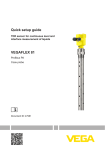
Quick setup guide
Submersible pressure transmitter with
ceramic measuring cell
VEGABAR 86
Foundation Fieldbus
Document ID: 46323
Contents
Contents
1 For your safety
1.1 Authorised personnel........................................................................................................ 3
1.2 Appropriate use................................................................................................................. 3
1.3 Warning about incorrect use.............................................................................................. 3
1.4 General safety instructions................................................................................................ 3
1.5 CE conformity.................................................................................................................... 3
1.6 Permissible process pressure........................................................................................... 3
1.7 NAMUR recommendations............................................................................................... 4
1.8 Environmental instructions................................................................................................ 4
2 Product description
2.1 Configuration..................................................................................................................... 5
3Mounting
3.1 General instructions for use of the instrument................................................................... 7
3.2 Ventilation and pressure compensation............................................................................. 7
4 Connecting to the bus system
4.1Connecting........................................................................................................................ 8
4.2 Single chamber housing.................................................................................................... 9
4.3 Double chamber housing................................................................................................ 10
5 Set up with the display and adjustment module
5.1 Insert display and adjustment module............................................................................. 12
5.2 Parameter adjustment - Quick setup............................................................................... 13
5.3 Parameter adjustment - Extended adjustment................................................................ 14
6Supplement
6.1 Technical data................................................................................................................. 17
Information:
This quick setup guide enables quick setup and commissioning of
your instrument.
Operating instructions VEGABAR 86 - Foundation Fieldbus:
Document-ID 45043
Editing status of the quick setup guide: 2014-07-30
2
VEGABAR 86 • Foundation Fieldbus
46323-EN-140801
You can find supplementary information in the corresponding, more
detailed Operating Instructions Manual as well as the Safety Manual
that comes with instruments with SIL qualification. These manuals are
available on the supplied DVD or in the download area of "www.vega.
com".
1 For your safety
1 For your safety
1.1 Authorised personnel
All operations described in this operating instructions manual must
be carried out only by trained specialist personnel authorised by the
plant operator.
During work on and with the device the required personal protective
equipment must always be worn.
1.2 Appropriate use
Model VEGABAR 86 is a pressure transmitter for level and gauge
measurement.
You can find detailed information about the area of application in
chapter "Product description".
Operational reliability is ensured only if the instrument is properly
used according to the specifications in the operating instructions
manual as well as possible supplementary instructions.
1.3 Warning about incorrect use
Inappropriate or incorrect use of the instrument can give rise to
application-specific hazards, e.g. vessel overfill or damage to system
components through incorrect mounting or adjustment.
1.4 General safety instructions
This is a high-tech instrument requiring the strict observance of standard regulations and guidelines. The user must take note of the safety
instructions in this operating instructions manual, the country-specific
installation standards as well as all prevailing safety regulations and
accident prevention rules.
The instrument must only be operated in a technically flawless and
reliable condition. The operator is responsible for trouble-free operation of the instrument.
During the entire duration of use, the user is obliged to determine the
compliance of the necessary occupational safety measures with the
current valid rules and regulations and also take note of new regulations.
1.5 CE conformity
46323-EN-140801
The device fulfills the legal requirements of the applicable EC guidelines. By affixing the CE marking, we confirm successful testing of the
product.
You can find the CE Certificate of Conformity in the download section
of our homepage.
1.6 Permissible process pressure
The permissible process pressure is specified on the type label with
"Process pressure", see chapter "Configuration". For safety reasons,
VEGABAR 86 • Foundation Fieldbus
3
1 For your safety
this range may not be exceeded. This applies even if a measuring cell
with a measuring range (order-related) higher than the permissible
pressure range of the process fitting is installed.
1.7 NAMUR recommendations
NAMUR is the automation technology user association in the process
industry in Germany. The published NAMUR recommendations are
accepted as the standard in field instrumentation.
The device fulfills the requirements of the following NAMUR recommendations:
•
•
•
NE 21 – Electromagnetic compatibility of equipment
NE 53 – Compatibility of field devices and display/adjustment
components
NE 107 – Self-monitoring and diagnosis of field devices
For further information see www.namur.de.
1.8 Environmental instructions
Protection of the environment is one of our most important duties.
That is why we have introduced an environment management system
with the goal of continuously improving company environmental protection. The environment management system is certified according
to DIN EN ISO 14001.
Please help us fulfill this obligation by observing the environmental
instructions in this manual:
•
•
Chapter "Packaging, transport and storage"
Chapter "Disposal"
46323-EN-140801
4
VEGABAR 86 • Foundation Fieldbus
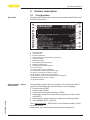
2 Product description
2 Product description
Type label
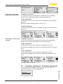
2.1 Configuration
The type label contains the most important data for identification and
use of the instrument:
1
2
3
4
5
6
7
8
9
10
17
16
15
14
13
12
11
Fig. 1: Layout of the type label (example)
1 Instrument type
2 Product code
3 Field for approvals
4 Power supply and signal output, electronics
5 Protection rating
6 Measuring range
7 Permissible process pressure
8 Material, wetted parts
9 Hardware and software version
10 Order number
11 Serial number of the instrument
12 Data-Matrix-Code for Smartphone-App
13 Symbol of the device protection class
14 ID numbers, instrument documentation
15 Reminder to observe the instrument documentation
16 Notified authority for CE marking
17 Approval directive
46323-EN-140801
Serial number - Instrument search
The type label contains the serial number of the instrument. With it
you can find the following instrument data on our homepage:
•
•
•
•
•
•
Product code (HTML)
Delivery date (HTML)
Order-specific instrument features (HTML)
Operating instructions and quick setup guide at the time of shipment (PDF)
Order-specific sensor data for an electronics exchange (XML)
Test certificate (PDF) - optional
Go to www.vega.com, "VEGA Tools" and "Instrument search". Enter
the serial number.
Alternatively, you can access the data via your smartphone:
VEGABAR 86 • Foundation Fieldbus
5
2 Product description
•
•
•
Download the smartphone app "VEGA Tools" from the "Apple App
Store" or the "Google Play Store"
Scan the Data Matrix code on the type label of the instrument or
Enter the serial number manually in the app
46323-EN-140801
6
VEGABAR 86 • Foundation Fieldbus
3 Mounting
3Mounting
Protection against moisture
3.1 General instructions for use of the instrument
Protect your instrument against moisture ingress through the following
measures:
•
•
•
•
Use the recommended cable (see chapter "Connecting to power
supply")
Tighten the cable gland
When mounting horizontally, turn the housing so that the cable
gland points downward
Loop the connection cable downward in front of the cable gland
This applies particularly to:
•
•
•
Instruments in non-Ex
and Ex-ia version
Outdoor mounting
Installations in areas where high humidity is expected (e.g. through
cleaning processes)
Installations on cooled or heated vessels
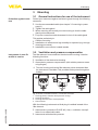
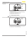
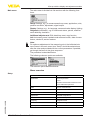
3.2 Ventilation and pressure compensation
The filter element is mounted into the electronics housing. It has the
following functions:
•
•
Ventilation of the electronics housing
Atmospheric pressure compensation (with relative pressure measuring ranges)
→ Turn the housing so that the filter element points downward after
the instrument is installed. This provides better protection against
buildup.
4
4
1
4
2
3
Fig. 2: Position of the filter element - non-Ex, Ex-ia version
1
2
3
4
Housing plastic, stainless steel precision casting
Housing aluminium
Housing stainless steel, electropolished
Filter element
46323-EN-140801
With the following instruments a blind plug is installed instead of the
filter element:
•
•
Instruments in protection IP 66/IP 68 (1 bar) - ventilation via capillaries in non-detachable cable
Instruments with absolute pressure
VEGABAR 86 • Foundation Fieldbus
7
4 Connecting to the bus system
4 Connecting to the bus system
Connection technology
4.1Connecting
The voltage supply and signal output are connected via the springloaded terminals in the housing.
Connection to the display and adjustment module or to the interface
adapter is carried out via contact pins in the housing.
Information:
The terminal block is pluggable and can be removed from the
electronics. To do this, lift the terminal block with a small screwdriver
and pull it out. When reinserting the terminal block, you should hear it
snap in.
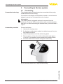
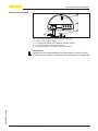
Connection procedure
Proceed as follows:
1. Unscrew the housing cover
2. If a display and adjustment module is installed, remove it by turning it slightly to the left.
3. Loosen compression nut of the cable entry gland
4. Remove approx. 10 cm (4 in) of the cable mantle, strip approx.
1 cm (0.4 in) of insulation from the ends of the individual wires
5. Insert the cable into the sensor through the cable entry
Fig. 3: Connection steps 5 and 6 - Single chamber housing
46323-EN-140801
8
VEGABAR 86 • Foundation Fieldbus
4 Connecting to the bus system
Fig. 4: Connection steps 5 and 6 - Double chamber housing
6. Insert the wire ends into the terminals according to the wiring plan
Information:
Solid cores as well as flexible cores with wire end sleeves are inserted directly into the terminal openings. In case of flexible cores without
end sleeves, press the terminal from above with a small screwdriver,
the terminal opening is then free. When the screwdriver is released,
the terminal closes again.
You can find further information on the max. wire cross-section under
"Technical data/Electromechanical data"
7. Check the hold of the wires in the terminals by lightly pulling on
them
8. Connect the screen to the internal ground terminal, connect the
outer ground terminal to potential equalisation
9. Tighten the compression nut of the cable entry gland. The seal
ring must completely encircle the cable
10. Reinsert the display and adjustment module, if one was installed
11. Screw the housing cover back on
The electrical connection is finished.
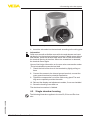
4.2 Single chamber housing
46323-EN-140801
The following illustration applies to the non-Ex, Ex-ia and Ex-d version.
VEGABAR 86 • Foundation Fieldbus
9
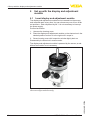
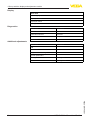
4 Connecting to the bus system
Electronics and terminal
compartment
2
3
4
1
1
0
0
Bus
(+)1
2(-)
5
6
7
8
5
1
Fig. 5: Electronics and terminal compartment, single chamber housing
1
2
3
4
5
Voltage supply, signal output
Contact pins for the display and adjustment module or interface adapter
Simulation switch ("1" = mode for simulation release)
For external display and adjustment unit
Ground terminal for connection of the cable screen
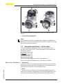
4.3 Double chamber housing
Electronics compartment
The following illustrations apply to the non-Ex as well as to the Ex-ia
version.
2
3
1
1
0
0
Bus
(+)1
2(-)
1
5
6
7
8
1
Fig. 6: Electronics compartment, double chamber housing
1 Internal connection to the terminal compartment
2 Contact pins for the display and adjustment module or interface adapter
3 Simulation switch ("1" = mode for simulation release)
46323-EN-140801
10
VEGABAR 86 • Foundation Fieldbus
4 Connecting to the bus system
Terminal compartment
2
3
Bus
(+)1
2(-)
5
6
7
8
4
1
Fig. 7: Terminal compartment, double chamber housing
1
2
3
4
Voltage supply, signal output
For display and adjustment module or interface adapter
For external display and adjustment unit
Ground terminal for connection of the cable screen
46323-EN-140801
Information:
Parallel use of an external display and adjustment unit and a display
and adjustment module in the terminal compartment is not supported.
VEGABAR 86 • Foundation Fieldbus
11
5 Set up with the display and adjustment module
5 Set up with the display and adjustment
module
5.1 Insert display and adjustment module
The display and adjustment module can be inserted into the sensor
and removed again at any time. You can choose any one of four different positions - each displaced by 90°. It is not necessary to interrupt
the power supply.
Proceed as follows:
1. Unscrew the housing cover
2. Place the display and adjustment module on the electronics in the
desired position and turn it to the right until it snaps in.
3. Screw housing cover with inspection window tightly back on
Disassembly is carried out in reverse order.
The display and adjustment module is powered by the sensor, an additional connection is not necessary.
Fig. 8: Installing the display and adjustment module in the electronics compartment of the single chamber housing
46323-EN-140801
12
VEGABAR 86 • Foundation Fieldbus
5 Set up with the display and adjustment module
1
2
Fig. 9: Installing the display and adjustment module in the double chamber
housing
1 In the electronics compartment
2 In the terminal compartment
Note:
If you intend to retrofit the instrument with a display and adjustment
module for continuous measured value indication, a higher cover with
an inspection glass is required.
5.2 Parameter adjustment - Quick setup
To quickly and easily adapt the sensor to the application, select
the menu item "Quick setup" in the start graphic on the display and
adjustment module.
Carry out the following steps in the below sequence.
You can find "Extended adjustment" in the next sub-chapter.
46323-EN-140801
Quick setup - Presettings
1. Application
In this menu item, you activate/deactivate the slave for the electronic
differential pressure and select the application. The application comprises process pressure and level measurement.
2. Units
In this menu item you determine the adjustment and temperature
units of the instrument. Depending on the selected application in the
menu item "Application", different adjustment units are available.
VEGABAR 86 • Foundation Fieldbus
13
5 Set up with the display and adjustment module
Quick setup - Process
pressure measurement
3. Position correction
In this menu item you compensate the influence of the installation
position of the instrument (offset) on the measured value.
4. Zero adjustment
In this menu item you carry out the zero adjustment for the processs
pressure.
Enter the corresponding pressure value for 0 %.
5. Span adjustment
In this menu item you carry out the span adjustment for the processs
pressure
Enter the corresponding pressure value for 100 %.
Quick setup - Level meas- 3. Position correction
urement
In this menu item you compensate the influence of the installation
position of the instrument (offset) on the measured value.
4. Max. adjustment
In this menu item you carry out the max. adjustment for level
Enter the percentage value and the corresponding value for the max.
level.
5. Min. adjustment
In this menu item you carry out the min. adjustment for level
Enter the percentage value and the corresponding value for the min.
level.
The quick setup is finished.
5.3 Parameter adjustment - Extended adjustment
For technically demanding measuring points, you can carry out
extended settings in "Extended adjustment".
46323-EN-140801
14
VEGABAR 86 • Foundation Fieldbus
5 Set up with the display and adjustment module
Main menu
The main menu is divided into five sections with the following functions:
Setup: Settings, e.g., for measurement loop name, application, units,
position correction, adjustment, signal output
Display: Settings, e.g., for language, measured value display, lighting
Diagnosis: Information, e.g. on instrument status, pointer, measurement reliability, simulation
Additional adjustments: PIN, date/time, reset, copy function
Info: Instrument name, hardware and software version, date of manufacture, device ID, sensor features
Note:
For optimum adjustment of the measuring point, the individual submenu items in the main menu item "Setup" should be selected one
after the other and provided with the correct parameters. If possible,
go through the items in the given sequence.
The procedure is described below.
The following submenu points are available:
The submenu points described below.
Setup
Menu overview
Menu item
Parameter
Application
Process pressure
Level
Activation/Deactivation Slave for electronic differential pressure
Units
Unit of measurement
Temperature unit
Position correction
Adjustment
Zero/Min. adjustment
46323-EN-140801
Span/Max. adjustment
Damping
Integration time
Linearization
Linearization type
Lock adjustment
VEGABAR 86 • Foundation Fieldbus
15
5 Set up with the display and adjustment module
Display
Menu item
Menu language
Displayed value 1
Displayed value 2
Diagnostics
Backlight
Menu item
Parameter
Sensor status
Peak value indicator
Pressure
Temperature
Additional adjustments
Simulation
Menu item
Parameter
PIN
Date/Time
Copy instrument settings
Special parameters
Scaling
Scaling size
Scaling format
46323-EN-140801
16
VEGABAR 86 • Foundation Fieldbus
6 Supplement
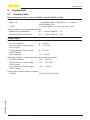
6Supplement
6.1
Technical data
Electromechanical data - version IP 66/IP 67 and IP 66/IP 68; 0.2 bar
Cable entry
ƲƲ M20 x 1.5
ƲƲ ½ NPT
1 x cable gland M20 x 1.5 (cable: ø 6 … 12 mm), 1 x
blind plug M20 x 1.5
1 x blind plug NPT, 1 x closing cap (red) ½ NPT
Wire cross-section (spring-loaded terminals)
ƲƲ Massive wire, stranded wire
ƲƲ Stranded wire with end sleeve
Voltage supply
Operating voltage
0.2 … 2.5 mm² (AWG 24 … 14)
0.2 … 1.5 mm² (AWG 24 … 16)
ƲƲ Non-Ex instrument
9 … 32 V DC
ƲƲ Ex-ia instrument - Power supply
ENTITY model
9 … 24 V DC
ƲƲ Ex-ia instrument - Power supply
FISCO model
9 … 17.5 V DC
ƲƲ Ex-d instrument
14 … 32 V DC
ƲƲ Non-Ex instrument
13.5 … 32 V DC
ƲƲ Ex-ia instrument - Power supply
ENTITY model
13.5 … 24 V DC
ƲƲ Fieldbus
max. 32 (max. 10 with Ex)
Operating voltage UB - illuminated display and adjustment module
ƲƲ Ex-ia instrument - Power supply
FISCO model
46323-EN-140801
Power supply by/max. number of sensors
13.5 … 17.5 V DC
VEGABAR 86 • Foundation Fieldbus
17
Notes
46323-EN-140801
18
VEGABAR 86 • Foundation Fieldbus
46323-EN-140801
Notes
VEGABAR 86 • Foundation Fieldbus
19
All statements concerning scope of delivery, application, practical use and operating conditions of the sensors and processing systems correspond to the information
available at the time of printing.
Subject to change without prior notice
© VEGA Grieshaber KG, Schiltach/Germany 2014
VEGA Grieshaber KG
Am Hohenstein 113
77761 Schiltach
Germany
Phone +49 7836 50-0
Fax +49 7836 50-201
E-mail: [email protected]
www.vega.com
46323-EN-140801
Printing date: