1
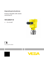
Operating Instructions
Pressure transmitter with ceramic
measuring cell
VEGABAR 82
4 … 20 mA/HART
Document ID: 45028
Contents
Contents
1 About this document
1.1Function............................................................................................................................ 4
1.2 Target group...................................................................................................................... 4
1.3 Symbolism used................................................................................................................ 4
2 For your safety
2.1 Authorised personnel........................................................................................................ 5
2.2 Appropriate use................................................................................................................. 5
2.3 Warning about incorrect use.............................................................................................. 5
2.4 General safety instructions................................................................................................ 5
2.5 CE conformity.................................................................................................................... 5
2.6 Measuring range - permissible process pressure.............................................................. 6
2.7 NAMUR recommendations............................................................................................... 6
2.8 Environmental instructions................................................................................................ 6
3 Product description
3.1 Configuration..................................................................................................................... 7
3.2 Principle of operation........................................................................................................ 8
3.3 Packaging, transport and storage.................................................................................... 11
3.4 Accessories and replacement parts................................................................................ 12
4Mounting
4.1 General instructions to use the instrument...................................................................... 14
4.2 Ventilation and pressure compensation........................................................................... 15
4.3 Process pressure measurement...................................................................................... 18
4.4 Level measurement......................................................................................................... 20
4.5 External housing............................................................................................................. 21
5 Connecting to power supply
5.1 Preparing the connection................................................................................................ 22
5.2Connecting...................................................................................................................... 23
5.3 Single chamber housing.................................................................................................. 24
5.4 Double chamber housing................................................................................................ 25
5.5 Double chamber housing Ex d........................................................................................ 27
5.6 Double chamber housing Ex d ia..................................................................................... 28
5.7 Double chamber housing with DIS-ADAPT..................................................................... 29
5.8 Housing IP 66/IP 68 (1 bar)............................................................................................. 29
5.9 External housing with version IP 68 (25 bar)................................................................... 30
5.10 Switch-on phase............................................................................................................. 31
7 Setup with PACTware
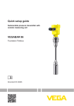
7.1 Connect the PC............................................................................................................... 51
7.2 Parameter adjustment..................................................................................................... 52
7.3 Saving the parameter adjustment data............................................................................ 53
2
VEGABAR 82 • 4 … 20 mA/HART
45028-EN-131010
6 Set up with the display and adjustment module
6.1 Insert display and adjustment module............................................................................. 33
6.2 Adjustment system.......................................................................................................... 34
6.3 Parameter adjustment - Quick setup............................................................................... 35
6.4 Parameter adjustment - Extended adjustment................................................................ 36
6.5 Saving the parameter adjustment data............................................................................ 50
Contents
8 Set up with other systems
8.1 DD adjustment programs................................................................................................ 54
8.2 Field Communicator 375, 475......................................................................................... 54
9 Diagnosis, asset management and service
9.1Maintenance................................................................................................................... 55
9.2 Diagnosis memory.......................................................................................................... 55
9.3 Asset Management function............................................................................................ 55
9.4 Rectify faults.................................................................................................................... 59
9.5 Calculation of total deviation (according to DIN 16086)................................................... 60
9.6 Exchange process assembly with version IP 68 (25 bar)................................................. 61
9.7 Exchanging the electronics module................................................................................. 62
9.8 Software update.............................................................................................................. 63
9.9 How to proceed in case of repair..................................................................................... 63
10Dismounting
10.1 Dismounting steps.......................................................................................................... 64
10.2Disposal.......................................................................................................................... 64
45028-EN-131010
11Supplement
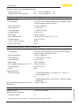
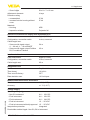
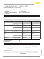
11.1 Technical data................................................................................................................. 65
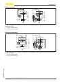
11.2Dimensions..................................................................................................................... 76
Safety instructions for Ex areas
Please note the Ex-specific safety information for installation and operation in Ex areas. These safety instructions are part of the operating
instructions manual and come with the Ex-approved instruments.
Editing status: 2013-09-25
VEGABAR 82 • 4 … 20 mA/HART
3
1 About this document
1 About this document
1.1Function
This operating instructions manual provides all the information you
need for mounting, connection and setup as well as important instructions for maintenance and fault rectification. Please read this information before putting the instrument into operation and keep this manual
accessible in the immediate vicinity of the device.
1.2 Target group
This operating instructions manual is directed to trained specialist
personnel. The contents of this manual should be made available to
these personnel and put into practice by them.
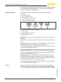
1.3 Symbolism used
Information, tip, note
This symbol indicates helpful additional information.
Caution: If this warning is ignored, faults or malfunctions can result.
Warning: If this warning is ignored, injury to persons and/or serious
damage to the instrument can result.
Danger: If this warning is ignored, serious injury to persons and/or
destruction of the instrument can result.
•
→
1
Ex applications
This symbol indicates special instructions for Ex applications.
List
The dot set in front indicates a list with no implied sequence.
Action
This arrow indicates a single action.
Sequence of actions
Numbers set in front indicate successive steps in a procedure.
Battery disposal
This symbol indicates special information about the disposal of batteries and accumulators.
45028-EN-131010
4
VEGABAR 82 • 4 … 20 mA/HART
2 For your safety
2 For your safety
2.1 Authorised personnel
All operations described in this operating instructions manual must
be carried out only by trained specialist personnel authorised by the
plant operator.
During work on and with the device the required personal protective
equipment must always be worn.
2.2 Appropriate use
The VEGABAR 82 is a pressure transmitter for process pressure and
hydrostatic level measurement.
You can find detailed information on the application range in chapter
"Product description".
Operational reliability is ensured only if the instrument is properly
used according to the specifications in the operating instructions
manual as well as possible supplementary instructions.
2.3 Warning about incorrect use
Inappropriate or incorrect use of the instrument can give rise to
application-specific hazards, e.g. vessel overfill or damage to system
components through incorrect mounting or adjustment.
2.4 General safety instructions
This is a high-tech instrument requiring the strict observance of standard regulations and guidelines. The user must take note of the safety
instructions in this operating instructions manual, the country-specific
installation standards as well as all prevailing safety regulations and
accident prevention rules.
The instrument must only be operated in a technically flawless and
reliable condition. The operator is responsible for trouble-free operation of the instrument.
During the entire duration of use, the user is obliged to determine the
compliance of the necessary occupational safety measures with the
current valid rules and regulations and also take note of new regulations.
2.5 CE conformity
45028-EN-131010
The device fulfills the legal requirements of the applicable EC guidelines. By affixing the CE marking, we confirm successful testing of the
product.
You can find the CE Certificate of Conformity in the download section
of our homepage.
Electromagnetic compatibility
Instruments with plastic housing as well as in four-wire or Ex-d-ia
version are designed for use in an industrial environment. Nevertheless, electromagnetic interference from electrical conductors and
VEGABAR 82 • 4 … 20 mA/HART
5
2 For your safety
radiated emissions must be taken into account, as is usual with a
class A instrument according to EN 61326-1. If the instrument is used
in a different environment, the electromagnetic compatibility to other
instruments must be ensured by suitable measures.
2.6 Measuring range - permissible process
pressure
The permissible process pressure is specified on the type label with
"process pressure", see chapter "Configuration". For safety reasons,
this range must not be exceeded. This applies also if a measuring
cell with higher measuring range (order-related) than the permissible
pressure range of the process fitting is installed.
2.7 NAMUR recommendations
NAMUR is the automation technology user association in the process
industry in Germany. The published NAMUR recommendations are
accepted as the standard in field instrumentation.
The device fulfills the requirements of the following NAMUR recommendations:
•
•
•
•
NE 21 – Electromagnetic compatibility of equipment
NE 43 – Signal level for malfunction information from measuring
transducers
NE 53 – Compatibility of field devices and display/adjustment
components
NE 107 – Self-monitoring and diagnosis of field devices
For further information see www.namur.de.
2.8 Environmental instructions
Protection of the environment is one of our most important duties.
That is why we have introduced an environment management system
with the goal of continuously improving company environmental protection. The environment management system is certified according
to DIN EN ISO 14001.
Please help us fulfill this obligation by observing the environmental
instructions in this manual:
•
•
Chapter "Packaging, transport and storage"
Chapter "Disposal"
45028-EN-131010
6
VEGABAR 82 • 4 … 20 mA/HART
3 Product description
3 Product description
Type plate
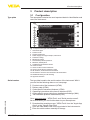
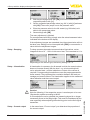
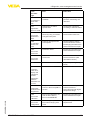
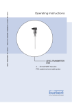
3.1 Configuration
The nameplate contains the most important data for identification and
use of the instrument:
1
2
3
4
5
6
7
8
9
10
16
15
14
13
12
11
Fig. 1: Layout of the type label (example)
1 Instrument type
2 Product code
3 Field for approvals
4 Power supply and signal output, electronics
5 Protection rating
6 Measuring range
7 Permissible process pressure
8 Material, wetted parts
9 Hardware and software version
10 Order number
11 Serial number of the instrument
12 Symbol of the device protection class
13 ID numbers, instrument documentation
14 Reminder to observe the instrument documentation
15 Notified authority for CE marking
16 Approval directive
Serial number
The type label contains the serial number of the instrument. With it
you can find the following data on our homepage:
•
•
•
•
•
•
Product code of the instrument (HTML)
Delivery date (HTML)
Order-specific instrument features (HTML)
Operating instructions at the time of shipment (PDF)
Order-specific sensor data for an electronics exchange (XML)
Test certificate pressure transmitters (PDF)
45028-EN-131010
Go to www.vega.com, "VEGA Tools" and "Serial number search".
As an alternative, you can find the data via your Smartphone:
•
•
•
Download the smartphone app "VEGA Tools" from the "Apple App
Store" or the "Google Play Store"
Scan the Data Matrix code on the type label of the instrument or
Enter the serial number manually in the app
VEGABAR 82 • 4 … 20 mA/HART
7
3 Product description
Scope of this operating
instructions manual
This operating instructions manual applies to the following instrument
versions:
Scope of delivery
The scope of delivery encompasses:
Measured variables
The VEGABAR 82 is suitable for the measurement of the following
process variables:
•
•
•
•
Hardware from 1.0.0
Software version from 1.0.0
Pressure transmitter
Documentation
–– this operating instructions manual
–– Test certificate, pressure transmitters
–– Operating instructions manual "Display and adjustment module" (optional)
–– Supplementary instructions "GSM/GPRS radio module"
(optional)
–– Supplementary instructions manual "Heating for display and
adjustment module" (optional)
–– Supplementary instructions manual "Plug connector for continuously measuring sensors" (optional)
–– Ex-specific "Safety instructions" (with Ex versions)
–– if necessary, further certificates
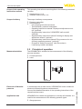
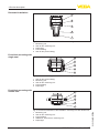
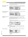
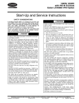
3.2 Principle of operation
•
•
Process pressure
Level
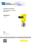
Fig. 2: Process pressure measurement VEGABAR 82
In combination with a slave sensor, VEGABAR 82 is also suitable for
electronic differential pressure measurement.
Application area
VEGABAR 82 is suitable for applications in virtually all industries. It is
used for the measurement of the following pressure types.
You can find detailed information in the operating instructions of the
respective slave sensor.
•
8
Gauge pressure
VEGABAR 82 • 4 … 20 mA/HART
45028-EN-131010
Electronic differential
pressure
3 Product description
•
•
Absolute pressure
Vacuum
Measured products
Measured products are gases, vapours and liquids.
Measuring system
Sensor element is the CERTEC® measuring cell with robust ceramic
diaphragm. The process pressure deflects the ceramic diaphragm
and causes a capacitance change in the measuring cell. This capacitance change is converted into an electrical signal and outputted as
measured value via the output signal.
Depending on the process fitting and measurement setup, measured
products can be also viscous or contain abrasive substances.
The CERTEC® measuring cell is available in two sizes:
•
•
ø 17.5 mm with small process fittings and pressure measuring
range 100 bar
ø 28 mm with large process fittings as well as all flange connections
The CERTEC® measuring cell has also an integrated temperature
sensor. The temperature value is outputted through:
•
•
•
Pressure types
The display and adjustment module
The current output
The digital signal output
The measuring cell design depends on the selected pressure type.
Relative pressure: the measuring cell is open to atmosphere. The
ambient pressure is detected in the measuring cell and compensated.
It thus has no influence on the measured value.
Absolute pressure: the measuring cell is evacuated and encapsulated. The ambient pressure is not compensated and does hence
influence the measured value.
Relative pressure, climate-compensated: the measuring cell is
evacuated and encapsulated. The ambient pressure is detected
through a reference sensor in the electronics and compensated. It
thus has no influence on the measured value.
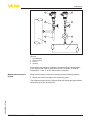
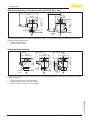
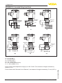
The following presentations show the installation of the CERTEC®
measuring cell into the process fitting and the different seal concepts.
45028-EN-131010
Seal concepts
VEGABAR 82 • 4 … 20 mA/HART
9
3 Product description
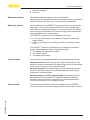
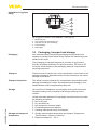
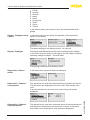
Recessed installation
1
2
3
4
5
Fig. 3: Recessed installation of the CERTEC® measuring cell
1
2
3
4
5
Measuring cell
Seal for the measuring cell
Diaphragm
Process fitting
Seal for the process fitting
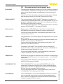
Front-flush mounting with
single seal
1
2
3
4
5
Fig. 4: Front-flish mounting of the CERTEC® measuring cell
1
2
3
4
5
Seal for the process fitting
Measuring cell
Seal for the measuring cell
Process fitting
Diaphragm
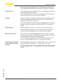
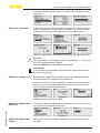
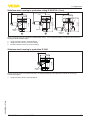
Front-flush mounting with
double seal
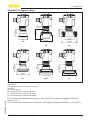
1
2
3
4
5
1
2
3
4
5
10
Measuring cell
Seal for the measuring cell
Process fitting
Additional, front seal for measuring cell
Diaphragm
VEGABAR 82 • 4 … 20 mA/HART
45028-EN-131010
Fig. 5: Front-flush installation of the CERTEC® measuring cell with double seal
3 Product description
Installation in hygienic
fitting
1
2
3
4
5
Fig. 6: Hygienic installation of the CERTEC measuring cell
®
1
2
3
4
5
Packaging
Measuring cell
Form seal for the measuring cell
Gap-free seal for process fitting
Process fitting
Diaphragm
3.3 Packaging, transport and storage
Your instrument was protected by packaging during transport. Its
capacity to handle normal loads during transport is assured by a test
based on ISO 4180.
The packaging of standard instruments consists of environmentfriendly, recyclable cardboard. For special versions, PE foam or PE
foil is also used. Dispose of the packaging material via specialised
recycling companies.
Transport
Transport must be carried out in due consideration of the notes on the
transport packaging. Nonobservance of these instructions can cause
damage to the device.
Transport inspection
The delivery must be checked for completeness and possible transit
damage immediately at receipt. Ascertained transit damage or concealed defects must be appropriately dealt with.
Storage
Up to the time of installation, the packages must be left closed and
stored according to the orientation and storage markings on the
outside.
45028-EN-131010
Unless otherwise indicated, the packages must be stored only under
the following conditions:
Storage and transport
temperature
•
•
•
•
•
•
•
Not in the open
Dry and dust free
Not exposed to corrosive media
Protected against solar radiation
Avoiding mechanical shock and vibration
Storage and transport temperature see chapter "Supplement Technical data - Ambient conditions"
Relative humidity 20 … 85 %
VEGABAR 82 • 4 … 20 mA/HART
11
3 Product description
PLICSCOM
3.4 Accessories and replacement parts
The display and adjustment module PLICSCOM is used for measured
value indication, adjustment and diagnosis. It can be inserted into the
sensor or the external display and adjustment unit and removed at
any time.
You can find further information in the operating instructions "Display
and adjustment module PLICSCOM" (Document-ID 27835).
VEGACONNECT
The interface adapter VEGACONNECT enables the connection of
communication-capable instruments to the USB interface of a PC. For
parameter adjustment of these instruments, the adjustment software
PACTware with VEGA-DTM is required.
You can find further information in the operating instructions "Interface
adapter VEGACONNECT" (Document-ID 32628).
Slave sensors
Slave sensors of VEGABAR series 80 enable in conjunction with
VEGABAR 82 an electronic differential pressure measurement.
You can find further information in the operating instructions of the
respective slave sensor.
VEGADIS 81
The VEGADIS 81 is an external display and adjustment unit for VEGA
plics® sensors.
For sensors with double chamber housing the interface adapter "DISADAPT" is also required for VEGADIS 81.
You can find further information in the operating instructions "VEGADIS 81" (Document-ID 43814).
DIS-ADAPT
The adapter "DIS-ADAPT" is an accessory part for sensors with
double chamber housings. It enables the connection of VEGADIS 81
to the sensor housing via an M12 x 1 plug.
You can find further information in the supplementary instructions
"Adapter DISADAPT" (Document-ID 45250).
VEGADIS 62
VEGADIS 62 is suitable for measured value indication and adjustment
of sensors with HART protocol. It is looped into the 4 … 20 mA/HART
signal cable.
You can find further information in the operating instructions "VEGADIS 62" (Document-ID 36469).
PLICSMOBILE T61
The PLICSMOBILE T61 is an external GSM/GPRS radio unit for
transmission of measured values and for remote parameter adjustment of plics® sensors. The adjustment is carried out via PACTware/
DTM by using the integrated USB connection.
PLICSMOBILE
12
The PLICSMOBILE is an internal GSM/GPRS radio unit for transmission of measured values and for remote parameter adjustment of
plics® sensors. The adjustment is carried out via PACTware/DTM by
using the integrated USB connection.
VEGABAR 82 • 4 … 20 mA/HART
45028-EN-131010
You can find further information in the supplementary instructions
"PLICSMOBILE T61" (Document-ID 37700).
3 Product description
You can find further information in the supplementary instructions
"PLICSMOBILE GSM/GPRS radio module" (Document-ID 36849).
Protective cap
The protective cover protects the sensor housing against soiling and
intense heat from solar radiation.
You will find additional information in the supplementary instructions
manual "Protective cover" (Document-ID 34296).
Flanges
Screwed flanges are available in different versions according to the
following standards: DIN 2501, EN 1092-1, BS 10, ANSI B 16.5,
JIS B 2210-1984, GOST 12821-80.
You can find additional information in the supplementary instructions
manual "Flanges according to DIN-EN-ASME-JIS" (Document-ID
31088).
Welded socket
Welded sockets are used to connect the sensors to the process.
Electronics module
The electronics module VEGABAR series 80 is a replacement part
for pressure transmitters of VEGABAR series 80. There is a different
version available for each type of signal output.
You can find further information in the supplementary instructions
"Welded socket VEGABAR series 80" (Document-ID 45082).
You can find further information in the operating instructions "Electronics module VEGABAR series 80" (Document-ID 45054).
The supplementary electronics is a replacement part for sensors with
double chamber housing and 4 … 20 mA/HART - two-wire.
You can find further information in the operating instructions "Supplementary electronics for 4 … 20 mA/HART - two-wire" (Document-ID
42764).
45028-EN-131010
Supplementary electronics for double chamber
housing
VEGABAR 82 • 4 … 20 mA/HART
13
4 Mounting
4Mounting
4.1 General instructions to use the instrument
Suitability for the process Make sure that all parts of the instrument exposed to the process are
conditions
suitable for the existing process conditions.
These are mainly:
•
•
•
Active measuring component
Process fitting
Process seal
•
•
•
•
Process pressure
Process temperature
Chemical properties of the medium
Abrasion and mechanical influences
Process conditions are particularly:
You can find the specifications of the process conditions in chapter
"Technical data" as well as on the nameplate.
Protection against moisture
Protect your instrument further through the following measures
against moisture penetration:
•
•
•
Use the recommended cable (see chapter "Connecting to power
supply")
Tighten the cable gland
Loop the connection cable downward in front of the cable gland
This applies particularly to:
•
•
•
Screwing in
Outdoor mounting
Installations in areas where high humidity is expected (e.g. through
cleaning processes)
Installations on cooled or heated vessels
On instruments with process fitting thread, the hexagon must be tightened with a suitable screwdriver. Wrench size see chapter "Dimensions".
Warning:
The housing must not be used to screw the instrument in! Applying
tightening force can damage internal parts of the housing.
In case of strong vibrations at the mounting location, the instrument
version with external housing should be used. See chapter "External
housing".
Temperature limits
Higher process temperatures often mean also higher ambient
temperatures. Make sure that the upper temperature limits stated in
chapter "Technical data" for the environment of the electronics housing and connection cable are not exceeded.
14
VEGABAR 82 • 4 … 20 mA/HART
45028-EN-131010
Vibrations
4 Mounting
2
1
Fig. 7: Temperature ranges
1 Process temperature
2 Ambient temperature
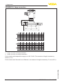
Filter elements
4.2 Ventilation and pressure compensation
Ventilation and pressure compensation are carried out with VEGABAR 82 via a filter element. It is air permeable and moistureblocking.
Caution:
The filter element causes a time-delayed pressure compensation.
When quickly opening/closing the housing cover, the measured value
can change for approx. 5 s by up to 15 mbar.
For effective ventilation, the filter element must always be free of
buildup.
Caution:
Do not use a high-pressure cleaner. The filter element could be damaged, which would allow moisture into the housing.
The following paragraphs describe how the filter element is arranged
in the different instrument versions.
The filter element is mounted into the electronics housing. It has the
following functions:
•
•
Ventilation electronics housing
Atmospheric pressure compensation (with relative pressure measuring ranges)
45028-EN-131010
Instruments in non-Ex,
Ex-ia and Ex-d-ia version
VEGABAR 82 • 4 … 20 mA/HART
15
4 Mounting
6
6
1
6
2
3
6
6
4
5
Fig. 8: Position of the filter element - non-Ex, Ex-ia and Ex-d-ia version
1
2
3
4
5
6
Single chamber housing plastic, stainless steel (precision casting)
Single chamber housing Aluminium
Single chamber housing, stainless steel electropolished
Double chamber housing plastic
Double chamber housing Aluminium
Filter element
With the following instruments a blind plug is installed instead of the
filter element:
•
•
Instruments in Ex-d version
Instruments in protection IP 66/IP 68 (1 bar) - ventilation via capillaries in fix connected cable
Instruments with absolut pressure
The filter element is integrated in the process assembly. It is located in
a rotatable metal ring and has the following function:
•
Atmospheric pressure compensation (with relative pressure measuring ranges)
Turn the metal ring in such a way that the filter element points downward after installtion of the instrument. This provides better protection
against buildup.
45028-EN-131010
16
VEGABAR 82 • 4 … 20 mA/HART
4 Mounting
3
3
4
4
1
2
Fig. 9: Position of the filter element - Ex-d version
1
2
3
4
Single chamber housing, aluminium, stainless steel precision casting
Double chamber housing, aluminium, stainless steel precision casting
Rotatable metal ring
Filter element
Instruments with absolute pressure have a blind plug mounted
instead of the filter element.
Instruments with Second
Line of Defense
The filter element is mounted into the electronics housing. It has the
following functions:
•
•
Ventilation electronics housing
Atmospheric pressure compensation (with relative pressure measuring ranges)
The process assembly of instruments with Second Line of Defense
(gastight leadthrough) is completely encapsulated. An absolute pressure measuring cell is used so that no ventilation is required.
1
1
Fig. 10: Position of the filter element - gastight leadthrough
1 Filter element
45028-EN-131010
With relative pressure measuring ranges, the ambient pressure is
detected and compensated by a reference sensor in the electronics.
Instruments in IP 69K
version
The filter element is mounted into the electronics housing. It has the
following functions:
•
•
Ventilation electronics housing
Atmospheric pressure compensation (with relative pressure measuring ranges)
VEGABAR 82 • 4 … 20 mA/HART
17
4 Mounting
1
Fig. 11: Position of the filter element - IP 69K version
1 Filter element
Instruments with absolute pressure have a blind plug mounted
instead of the filter element.
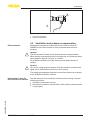
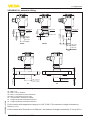
Measurement setup in
gases
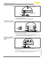
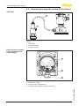
4.3 Process pressure measurement
Keep the following in mind when setting up the measuring system:
•
Mount the instrument above the measuring point
Possible condensation can then drain off into the process line.
1
2
3
Fig. 12: Measurement setup for process pressure measurement of gases in
pipelines
1 VEGABAR 82
2 Blocking valve
3 Pipeline
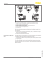
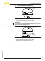
Measurement setup in
vapours
Keep the following in mind when setting up the measuring system:
•
•
•
Connect via a siphon
Do not insulate the siphon
Fill the siphon with water before setup
45028-EN-131010
18
VEGABAR 82 • 4 … 20 mA/HART
4 Mounting
1
1
2
2
3
3
4
4
Fig. 13: Measurement setup with process pressure measurement of gases in
pipelines
1
2
3
4
VEGABAR 82
Blocking valve
Siphon
Pipeline
A protective accumulation of water is formed through condensation
in the pipe bends. Even in applications with hot steam, a medium
temperature < 100 °C on the transmitter is ensured.
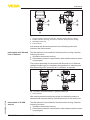
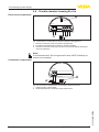
Measurement setup in
liquids
Keep the following in mind when setting up the measuring system:
•
Mount the instrument below the measuring point
45028-EN-131010
The effective pressure line is always filled with liquid and gas bubbles
can bubble up to the process line.
VEGABAR 82 • 4 … 20 mA/HART
19
4 Mounting
3
2
1
Fig. 14: Measurement setup for process pressure measurement of liquids in
pipelines
1 VEGABAR 82
2 Blocking valve
3 Pipeline
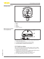
Measurement setup
4.4 Level measurement
Keep the following in mind when setting up the measuring system:
•
•
•
Mount the instrument below the min. level
Do not mount the instrument close to the filling stream or emptying
area
Mount the instrument so that it is protected against pressure
shocks from the stirrer
Fig. 15: Measurement setup for level measurement
45028-EN-131010
20
VEGABAR 82 • 4 … 20 mA/HART
4 Mounting
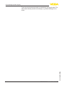
Configuration
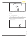
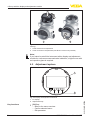
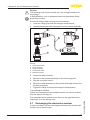
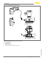
4.5 External housing
4
3
2
5
1
Fig. 16: Setup process assembly, external housing
1
2
3
4
Mounting
Process assembly
Connection cable process assembly - External housing
External housing
Signal cable
1. Mark the holes according to the following drilling template
2. Fasten wall mounting plate with 4 screws
90 mm
(3.54")
70 mm
(2.76")
3mm
(0.12")
mm
3,5 4")
.1
0
(
93 mm
(3.66")
110 mm
(4.33")
R
8 mm
(0.32")
45028-EN-131010
Fig. 17: Drilling template - wall mounting plate
VEGABAR 82 • 4 … 20 mA/HART
21
5 Connecting to power supply
5 Connecting to power supply
Safety instructions
Voltage supply
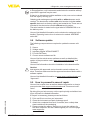
5.1 Preparing the connection
Always keep in mind the following safety instructions:
•
•
Connect only in the complete absence of line voltage
If overvoltage surges are expected, overvoltage arresters should
be installed
Power supply and current signal are carried on the same two-wire
cable. The operating voltage can differ depending on the instrument
version.
The data for power supply are specified in chapter "Technical data".
Provide a reliable separation between the supply circuit and the
mains circuits according to DIN EN 61140 VDE 0140-1.
Keep in mind the following additional factors that influence the operating voltage:
•
•
Connection cable
Lower output voltage of the power supply unit under nominal load
(e.g. with a sensor current of 20.5 mA or 22 mA in case of fault
message)
Influence of additional instruments in the circuit (see load values in
chapter "Technical data")
The instrument is connected with standard two-wire cable without
screen. If electromagnetic interference is expected which is above the
test values of EN 61326-1 for industrial areas, screened cable should
be used.
Use cable with round cross section for instruments with housing and
cable gland. To ensure the seal effect of the cable gland (IP protection
rating), find out which cable outer diameter the cable gland is suitable
for.
•
•
•
5 … 9 mm (0.20 … 0.35 in)
6 … 12 mm (0.24 … 0.47 in)
10 … 14 mm (0.40 … 0.55 in)
Use a cable gland fitting the cable diameter.
We generally recommend the use of screened cable for HART multidrop mode.
Cable gland ½ NPT
With plastic housing, the NPT cable gland or the Conduit steel tube
must be screwed without grease into the threaded insert.
Max. torque for all housings see chapter "Technical data".
If screened cable is required, we recommend connecting the cable
screen on both ends to ground potential. In the sensor, the screen
must be connected directly to the internal ground terminal. The
ground terminal on the outside of the housing must be connected to
the ground potential (low impedance).
With Ex systems it must be ensured that the grounding corresponds
to the installation regulations.
22
VEGABAR 82 • 4 … 20 mA/HART
45028-EN-131010
Cable screening and
grounding
5 Connecting to power supply
In electroplating and CCP systems (cathodic corrosion protection) it
must be taken into account that significant potential differences exist.
This can lead to unacceptably high shield currents if the cable shield
is grounded at both ends.
Information:
The metallic parts of the instrument (process fitting, transmitter, concentric tube, etc.) are conductively connected with the inner and outer
ground terminal on the housing. This connection exists either directly
via connecting metallic parts or, in case of instruments with external
electronics, via the screen of the special connection cable.
You can find specifications on the potential connections inside the
instrument in chapter "Technical data".
Connection technology
5.2Connecting
The voltage supply and signal output are connected via the springloaded terminals in the housing.
The connection to the display and adjustment module or to the interface adapter is carried out via contact pins in the housing.
Information:
The terminal block is pluggable and can be removed from the
electronics. To do this, lift the terminal block with a small screwdriver
and pull it out. When reinserting the terminal block, you should hear it
snap in.
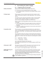
Connection procedure
Proceed as follows:
1. Unscrew the housing cover
2. If a display and adjustment module is installed, remove it by turning it slightly to the left.
3. Loosen compression nut of the cable entry
4. Remove approx. 10 cm (4 in) of the cable mantle, strip approx.
1 cm (0.4 in) of insulation from the ends of the individual wires
45028-EN-131010
5. Insert the cable into the sensor through the cable entry
Fig. 18: Connection steps 5 and 6 - Single chamber housing
VEGABAR 82 • 4 … 20 mA/HART
23
5 Connecting to power supply
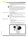
Fig. 19: Connection steps 5 and 6 - Double chamber housing
6. Insert the wire ends into the terminals according to the wiring plan
Information:
Solid cores as well as flexible cores with wire end sleeves are inserted directly into the terminal openings. In case of flexible cores without
end sleeves, press the terminal from above with a small screwdriver;
the terminal opening is freed. When the screwdriver is released, the
terminal closes again.
You can find further information on the max. wire cross-section under
"Technical data/Electromechanical data"
7. Check the hold of the wires in the terminals by lightly pulling on
them
8. Connect the screen to the internal ground terminal, connect the
outer ground terminal to potential equalisation
9. Tighten the compression nut of the cable entry. The seal ring must
completely encircle the cable
10. Reinsert the display and adjustment module, if one was installed
11. Screw the housing cover back on
The electrical connection is hence finished.
5.3 Single chamber housing
The following illustration applies to the non-Ex, Ex-ia, Ex-d vand Exd-ia version.
45028-EN-131010
24
VEGABAR 82 • 4 … 20 mA/HART
5 Connecting to power supply
Electronics and connection compartment
2
3
4...20mA
(+)1
2(-)
5
6
7
8
4
1
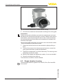
Fig. 20: Electronics and connection compartment, single chamber housing
1
2
3
4
Voltage supply/Signal output
For display and adjustment module or interface adapter
For external display and adjustment unit or Slave sensor
Ground terminal for connection of the cable screen
5.4 Double chamber housing
Electronics compartment
The following illustrations apply to the non-Ex as well as to the Ex-ia
version.
2
4...20mA
(+)1
2(-)
1
5
6
7 8
1
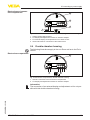
Fig. 21: Electronics compartment, double chamber housing
1 Internal connection to the connection compartment
2 For display and adjustment module or interface adapter
45028-EN-131010
Information:
The connection of an external display and adjustment unit is not possible with this double chamber housing.
VEGABAR 82 • 4 … 20 mA/HART
25
5 Connecting to power supply
Connection compartment
2
4...20mA
(+)1
3
2(-)
1
Fig. 22: Connection compartment, double chamber housing
1 Voltage supply/Signal output
2 For display and adjustment module or interface adapter
3 Ground terminal for connection of the cable screen
Connection compartment
- Second current output
II
4...20mA
I
4...20mA
(+)1
1
( +)7
2(-)
3
8(-)
2
Fig. 23: Connection compartment double chamber housing, supplementary
electronics - second current output
1 First current output (I) - Voltage supply and signal output (HART)
2 Second current output (II) - Voltage supply and signal output (without HART)
3 Ground terminal for connection of the cable screen
Connection compartment
- Radio module PLICSMOBILE
SIM-Card
Status
Test
USB
(+)1
2(-)
1
Fig. 24: Connection compartment radio module PLICSMOBILE
You can find detailed information on connection in the supplementary
instructions "PLICSMOBILE GSM/GPRS radio module".
26
VEGABAR 82 • 4 … 20 mA/HART
45028-EN-131010
1 Voltage supply
5 Connecting to power supply
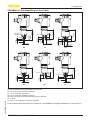
Electronics compartment
5.5 Double chamber housing Ex d
2
4...20mA
(+)1
2(-)
1
5
6
7 8
1
Fig. 25: Electronics compartment, double chamber housing
1 Internal connection to the connection compartment
2 For display and adjustment module or interface adapter
Connection compartment
Information:
The connection of an external display and adjustment unit is not possible with this double chamber housing.
2
4...20mA
(+)1
2(-)
3
1
Fig. 26: Connection compartment, double chamber housing
45028-EN-131010
1 Voltage supply/Signal output
2 For display and adjustment module or interface adapter
3 Ground terminal for connection of the cable screen
VEGABAR 82 • 4 … 20 mA/HART
27
5 Connecting to power supply
Electronics compartment
5.6 Double chamber housing Ex d ia
2
4...20mA
(+)1
2(-)
1
5
6
7 8
3
Fig. 27: Electronics compartment, double chamber housing Ex d ia
1 Internal connection to the connection compartment
2 For display and adjustment module or interface adapter
3 Internal connection to the plug connector for external display and adjustment unit (optional)
Connection compartment
Note:
If an instrument with Ex-d-ia approval is used, HART multidrop operation is not possible.
4...20mA
(+)1
2
2(-)
1
Fig. 28: Connection compartment, Ex-d double chamber housing
1 Voltage supply, signal output
2 Ground terminal for connection of the cable screen
45028-EN-131010
28
VEGABAR 82 • 4 … 20 mA/HART
5 Connecting to power supply
Electronics compartment
5.7 Double chamber housing with DIS-ADAPT
1
2
3
Fig. 29: View to the electronics compartment
1 DIS-ADAPT
2 Internal plug connection
3 Plug connector M12 x 1
Assignment of the plug
connector
4
3
1
2
Fig. 30: Top view of the plug connector
1
2
3
4
Wire assignment, connection cable
Pin 1
Pin 2
Pin 3
Pin 4
Contact pin
Colour connection cable in the sensor
Terminal, electronics
module
Pin 1
Brown
5
Pin 2
White
6
Pin 3
Blue
7
Pin 4
Black
8
5.8 Housing IP 66/IP 68 (1 bar)
1
45028-EN-131010
2
Fig. 31: Wire assignment fix-connected connection cable
1 brown (+) and blue (-) to power supply or to the processing system
2 Shielding
VEGABAR 82 • 4 … 20 mA/HART
29
5 Connecting to power supply
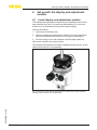
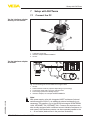
Overview
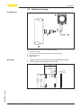
5.9 External housing with version IP 68 (25 bar)
3
2
1
Fig. 32: VEGABAR 82 in IP 68 version 25 bar with axial cable outlet, external
housing
1 Transmitter
2 Connection cable
3 External housing
Electronics and connection compartment for
power supply
1
4...20mA
(+)1
2(-)
5
6
7
8
2
3
Fig. 33: Electronics and connection compartment
1 Electronics module
2 Cable gland for voltage supply
3 Cable gland for connection cable, transmitter
45028-EN-131010
30
VEGABAR 82 • 4 … 20 mA/HART
5 Connecting to power supply
Terminal compartment,
housing socket
1 2 3 4
1
5
2
3
4
6
Fig. 34: Connection of the sensor in the housing base
1
2
3
4
5
6
Brown
Blue
Yellow
White
Shielding
Breather capillaries
Electronics and connection compartment
2
3
4...20mA
(+)1
2(-)
5
6
7
8
4
1
Fig. 35: Electronics and connection compartment, single chamber housing
1
2
3
4
Voltage supply/Signal output
For display and adjustment module or interface adapter
For external display and adjustment unit or Slave sensor
Ground terminal for connection of the cable screen
5.10 Switch-on phase
45028-EN-131010
After connecting the instrument to power supply or after a voltage
recurrence, the instrument carries out a self-check for approx. 10 s:
•
•
•
•
Internal check of the electronics
Indication of the instrument type, hardware and software version,
measurement loop name on the display or PC
Indication of a status message on the display or PC
The output signal jumps to the set error current
VEGABAR 82 • 4 … 20 mA/HART
31
5 Connecting to power supply
Then the actual measured value is outputted to the signal cable. The
value takes already carried out settings, e.g. default setting into account.
45028-EN-131010
32
VEGABAR 82 • 4 … 20 mA/HART
6 Set up with the display and adjustment module
6 Set up with the display and adjustment
module
6.1 Insert display and adjustment module
The display and adjustment module can be inserted into the sensor
and removed any time. Four positions displaced by 90° can be selected. It is not necessary to interrupt the power supply.
Proceed as follows:
1. Unscrew the housing cover
2. Place the display and adjustment module in the requested position onto the electronics and turn to the right until it snaps in
3. Screw housing cover with inspection window tightly back on
Removal is carried out in reverse order.
The display and adjustment module is powered by the sensor, an additional connection is not necessary.
45028-EN-131010
Fig. 36: Insertion of the display and adjustment module with single chamber
housing into the electronics compartment
VEGABAR 82 • 4 … 20 mA/HART
33
6 Set up with the display and adjustment module
1
2
Fig. 37: Insertion of the display and adjustment module into the double chamber
housing
1 In the electronics compartment
2 In the connection compartment (with Ex-d-ia version not possible)
Note:
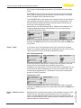
If you intend to retrofit the instrument with a display and adjustment
module for continuous measured value indication, a higher cover with
an inspection glass is required.
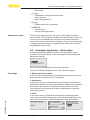
6.2 Adjustment system
1
2
Fig. 38: Display and adjustment elements
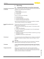
Key functions
34
•
45028-EN-131010
1 LC display
2 Adjustment keys
[OK] key:
–– Move to the menu overview
–– Confirm selected menu
–– Edit parameter
VEGABAR 82 • 4 … 20 mA/HART
6 Set up with the display and adjustment module
•
•
•
Adjustment system
–– Save value
[->] key:
–– Presentation, change measured value
–– Select list entry
–– Select editing position
[+] key:
–– Change value of the parameter
[ESC] key:
–– Interrupt input
–– Jump to next higher menu
The sensor is adjusted via the four keys of the display and adjustment module. The LC display indicates the individual menu items. The
functions of the individual keys are shown in the above illustration.
Approx. 60 minutes after the last pressing of a key, an automatic reset
to measured value indication is triggered. Any values not confirmed
with [OK] will not be saved.
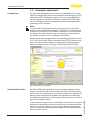
6.3 Parameter adjustment - Quick setup
To quickly and easily adapt the sensor to the application, select
the menu item "Quick setup" in the start graphic on the display and
adjustment module.
Carry out the following steps in the below sequence.
You can find "Extended adjustment" in the next sub-chapter.
Presettings
1. Measurement loop name
In the first menu item you assign a suitable measurement loop name.
Permitted are names with max. 19 characters.
45028-EN-131010
2. Application
In this menu item you activate/deactivate the slave for the electronic
differential pressure and select the application. With process pressure
transmitters, the selection comprises process pressure and level
measurement; with suspension pressure transmitters it comprises
level measurement.
3. Units
In this menu item you determine the adjustment and temperature
units of the instrument. Depending on the selected application in the
menu item "Application", different adjustment units are available.
VEGABAR 82 • 4 … 20 mA/HART
35
6 Set up with the display and adjustment module
Adjustment - Process
pressure measurement
4. Position correction
In this menu item you compensate the influence of the installation
position of the instrument (offset) to the measured value.
5. zero adjustment
In this menu item you carry out the zero adjustment for the processs
pressure.
Enter the respective pressure value for 0 %.
6. span adjustment
In this menu item you carry out the span adjustment for the processs
pressure
Enter the respective pressure value for 100 %.
Adjustment - Level measurement
4. Position correction
In this menu item you compensate the influence of the installation
position of the instrument (offset) to the measured value.
5. Max. adjustment
In this menu item you carry out the max. adjustment for level
Enter the percentage value and the corresponding value for the max.
level.
6. Min. adjustment
In this menu item you carry out the min. adjustment for level
Enter the percentage value and the corresponding value for the min.
level.
The quick setup is hence finished.
6.4 Parameter adjustment - Extended adjustment
For technically demanding measurement loops you can carry out
extended settings in "Extended adjustment".
36
The main menu is divided into five sections with the following functions:
VEGABAR 82 • 4 … 20 mA/HART
45028-EN-131010
Main menu
Main menu
6 Set up with the display and adjustment module
Setup: Settings, e.g., for measurement loop name, application, units,
position correction, adjustment, signal output
Display: Settings, e.g., for language, measured value display, lighting
Diagnosis: Information, e.g. on instrument status, pointer, measurement reliability, simulation
Additional adjustments: PIN, date/time, reset, copy function
Info: Instrument name, hardware and software version, date of manufacture, sensor features
In the main menu item "Setup", the individual submenu items should
be selected one after the other and provided with the correct parameter values.
The following submenu points are available:
In the following paragraphs the menu items of the menu "Setup" for
electronic differential pressure measurement are described. Depending on the selected application, different paragraphs are important.
The additional menu items of the menu "Setup" as well as the complete menus "Display", "Diagnosis", "Additional settings" and "Info"
are described in the operating instructions of the master sensor.
Setup - Measurement
loop name
In the menu item "Sensor TAG" you edit a twelve digit measurement
loop designation label.
You can enter an unambiguous designation for the sensor, e.g. the
measurement loop name or the tank or product designation. In digital
systems and in the documentation of larger plants, a singular designation must be entered for exact identification of individual measuring
points.
The available digits comprise:
45028-EN-131010
•
•
•
Setup - Application
Letters from A … Z
Numbers from 0 … 9
Special characters +, -, /, -
In this menu item you activate/deactivate the slave for electronic differential pressure and select the application.
If you have connected a slave sensor, you confirm this with "Activate".
VEGABAR 82 • 4 … 20 mA/HART
37
6 Set up with the display and adjustment module
If you have connected no slave sensor, you confirm this with "Deactivate".
VEGABAR 82 can be used for process pressure and level measurement. Default setting is process pressure measurement. The mode
can be changed in this adjustment menu.
The VEGABAR 82 in conjunction with a slave sensor can be used for
flow, differential pressure, density and interface measurement. The
default setting is differential pressure measurement. Switchover is
carried out in the adjustment menu.
Depending on the selected application, different subchapters in the
following adjustment steps are important. There you can find the
individual adjustment steps.
Enter the requested parameters via the appropriate keys, save your
settings with [OK] and jump to the next menu item with the [ESC] and
the [->] key.
Setup - Units
In this menu item, the adjustment units of the instrument are determined. The selection determines the displayed unit in the menu items
"Min. adjustment (zero)" and "Max. adjustment (span)".
Unit of measurement:
If the level should be adjusted in a height unit, the density of the medium must also be entered later during the adjustment.
In addition, the temperature unit of the instrument is specified. The selection determines the displayed unit in the menu items "Peak value,
measuring cell temperature", "Peak value, electronics temperature"
as well as "HART variables".
Temperature unit:
Enter the requested parameters via the appropriate keys, save your
settings with [OK] and jump to the next menu item with the [ESC] and
the [->] key.
38
Especially with chemical seal systems, the installation position of the
instrument can shift (offset) the measured value. The position correction compensates this offset. Hence the actual measured value is
taken over automatically. With relative pressure measuring cells also a
manual offset can be carried out.
VEGABAR 82 • 4 … 20 mA/HART
45028-EN-131010
Setup - Position correction
6 Set up with the display and adjustment module
If with the automatic position correction, the actual measured value
should be taken over as corrective value, then this value must not be
influeces by product covering or a static pressure.
With the manual position correction, the offset value can be determined by the user. Select for this purpose the function "Edit" and
enter the requested value.
Save your settings with [OK] and move with [ESC] and [->] to the
next menu item.
When the position correction was carried out, then the actual measured value is corrected to 0. The corrective value appears with inverse
signs as offset value in the display.
The position correction can be repeated as often as necessary. However, if the sum of the corrective values exceeds 20 % of the nominal
measuring range, then no position correction is possible.
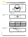
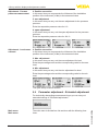
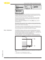
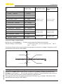
Setup - Adjustment
VEGABAR 82 always measures pressure independently of the process variable selected in the menu item "Application". To output the
selected process variable correctly, an allocation to 0 % and 100 % of
the output signal must be carried out (adjustment).
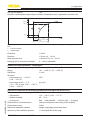
With the application "Level", the hydrostatic pressure, e.g. with full
and empty vessel, is entered for adjustment. See following example:
2
5m
(196.9")
100%
45028-EN-131010
0%
1
Fig. 39: Parameter adjustment example "Min./max. adjustment, level measurement"
1 Min. level = 0 % corresponds to 0.0 mbar
2 Max. level = 100 % corresponds to 490.5 mbar
VEGABAR 82 • 4 … 20 mA/HART
39
6 Set up with the display and adjustment module
If these values are not known, an adjustment with levels of for example 10 % and 90 % is also possible. By means of these settings, the
real filling height is then calculated.
The real product level during this adjustment is not important, because the min./max. adjustment is always carried out without changing the product level. These settings can be made ahead of time
without the instrument having to be installed.
Note:
If the adjustment ranges are exceeded, the entered value will not be
accepted. Editing can be interrupted with [ESC] or corrected to a
value within the adjustment ranges.
For the other process variables such as e.g. process pressure, differential pressure or flow, the adjustment is performed in like manner.
Setup - zero adjustment
Proceed as follows:
1. Select the menu item "Setup" with [->] and confirm with [OK].
Now select with [->] the menu item "zero adjustment" and confirm
with [OK].
2. Edit the mbar value with [OK] and set the cursor to the requested
position with [->].
3. Set the requested mbar value with [+] and store with [OK].
4. Move with [ESC] and [->] to the span adjustment
The zero adjustment is finished.
Information:
The zero adjustment shifts the value of the span adjustment. The
span, i.e. the difference between these values, however, remains
unchanged.
For an adjustment with pressure, simply enter the actual measured
value indicated at the bottom of the display.
If the adjustment ranges are exceeded, the message "Outside parameter limits" appears. The editing procedure can be aborted with [ESC]
or the displayed limit value can be accepted with [OK].
40
Proceed as follows:
1. Select with [->] the menu item "Span adjustment" and confirm
with [OK].
VEGABAR 82 • 4 … 20 mA/HART
45028-EN-131010
Setup - span adjustment
6 Set up with the display and adjustment module
2. Edit the mbar value with [OK] and set the cursor to the requested
position with [->].
3. Set the requested mbar value with [+] and store with [OK].
For an adjustment with pressure, simply enter the actual measured
value indicated at the bottom of the display.
If the adjustment ranges are exceeded, the message "Outside parameter limits" appears. The editing procedure can be aborted with [ESC]
or the displayed limit value can be accepted with [OK].
The span adjustment is finished.
Setup - Min. adjustment
Level
Proceed as follows:
1. Select the menu item "Setup" with [->] and confirm with [OK].
Now select with [->] the menu item "Adjustment", then "Min.
adjustment"and confirm with [OK].
2. Edit the percentage value with [OK] and set the cursor to the
requested position with [->].
3. Set the requested percentage value (e.g. 10 %) with [+] and save
with [OK]. The cursor jumps now to the pressure value.
4. Enter the pressure value corresponding to the min. level (e.g.
0 mbar).
5. Save settings with [OK] and move with [ESC] and [->] to the max.
adjustment.
The min. adjustment is finished.
For an adjustment with filling, simply enter the actual measured value
indicated at the bottom of the display.
45028-EN-131010
If the adjustment ranges are exceeded, then the entered value will not
be taken over. Editing can be interrupted with [ESC] or corrected to a
value within the adjustment ranges.
Setup - Max. adjustment
Level
Proceed as follows:
1. Select with [->] the menu item max. adjustment and confirm with
[OK].
VEGABAR 82 • 4 … 20 mA/HART
41
6 Set up with the display and adjustment module
2. Edit the percentage value with [OK] and set the cursor to the
requested position with [->].
3. Set the requested percentage value (e.g. 90 %) with [+] and save
with [OK]. The cursor jumps now to the pressure value.
4. Enter the pressure value for the full vessel (e.g. 900 mbar) suitable for the percentage value.
5. Save settings with [OK]
The max. adjustment is finished.
For an adjustment with filling, simply enter the actual measured value
indicated at the bottom of the display.
If the adjustment ranges are exceeded, then the entered value will not
be taken over. Editing can be interrupted with [ESC] or corrected to a
value within the adjustment ranges.
Setup - Damping
To damp process-dependent measured value fluctuations, set an
integration time of 0 … 999 s in this menu item. The increment is 0.1 s.
Depending on the sensor type, the factory setting is 0.1 s.
Setup - Linearization
A linearization is necessary for all vessels in which the vessel volume
does not increase linearly with the level - e.g. a horizontal cylindrical or spherical tank - and the indication or output of the volume is
required. Corresponding linearization curves are preprogrammed for
these vessels. They represent the correlation between the level percentage and vessel volume. The linearization applies to the measured
value indication and the current output.
Caution:
Note the following, if the respective sensor is used as part of an overfill protection system according to WHG:
Setup - Current output
42
In the menu items "Current output" you determine the properties of
the current output.
VEGABAR 82 • 4 … 20 mA/HART
45028-EN-131010
If a linearization curve is selected, the measuring signal is no longer
necessarily linear to the filling height. This must be considered by the
user especially when adjusting the switching point on the limit signal
transmitter.
6 Set up with the display and adjustment module
On instrumdents with integrated 2. current output, the properties for
each current output are adjusted individually. The following descriptions apply to both current outputs.
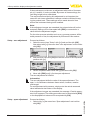
Setup - Current output 1
and 2 (mode)
In the menu item "Current output mode" you determine the output
characteristics and reaction of the current output in case of failure.
The default setting is output characteristics 4 … 20 mA, failure mode
< 3.6 mA.
Setup - Current output 1
and 2 (min./max.)
In the menu item "Current output Min./Max.", you determine the reaction of the current output during operation.
The default setting is min. current 3.8 mA and max. current 20.5 mA.
Lock/release setup - Adjustment
In the menu item "Lock/unlock adjustment", you can protect the
sensor parameters against unauthorized modification. The PIN is
activated/deactivated permanently.
The following adjustment functions are possible without entering the
PIN:
•
•
Select menu items and show data
Read data from the sensor into the display and adjustment module.
Caution:
With active PIN, adjustment via PACTware/DTM as well as other
systems is also blocked.
You can change the PIN number under "Additional adjustments PIN".
45028-EN-131010
Display - Language
This menu item enables the setting of the requested national language.
The following languages are available:
•
•
German
English
VEGABAR 82 • 4 … 20 mA/HART
43
6 Set up with the display and adjustment module
•
•
•
•
•
•
•
•
•
French
Spanish
Russian
Italian
Dutch
Portuguese
Polish
Czech
Turkish
In the delivery status, the sensor is set to the ordered national language.
Display - Displayed value
1 and 2
In this menu item you can define the indication of the measured
values on the display.
The default setting for the display value is "Lin. percent".
Display - Backlight
The display and adjustment module has a backlight for the display.
In this menu item you switch on the lighting. You can find the required
operating voltage in chapter "Technical data".
The lighting is switched off in delivery status.
Diagnostics - Device
status
In this menu item, the device status is displayed.
Diagnostics - Peak values, pressure
The respective min. and max. measured value is saved in the sensor.
The two values are displayed in the menu item "Peak values, pressure".
In another window you can carry out a reset of the peak values
separately.
44
The respective min. and max. measured values of the measuring cell
and electronics temperature are stored in the sensor. In the menu
item "Peak value, temperature", both values are displayed.
VEGABAR 82 • 4 … 20 mA/HART
45028-EN-131010
Diagnostics - Peak values, temperature
6 Set up with the display and adjustment module
In another window you can carry out a reset of the two peak values
separately.
Diagnosis - Simulation
In this menu item you can simulate measured values via the current
output. This allows the signal path to be tested, e.g. via downstream
indicating instruments or the input card of the control system.
Select the requested simulation size and adjust the requested value.
Caution:
During simulation, the simulated value is outputted as 4 … 20 mA current value and digital HART signal.
Push the [ESC] key to deactivate the simulation.
Information:
The simulation is terminated automatically 60 minutes after the last
key has been pushed.
Additional settings - PIN
By entering a 4-digit PIN, you protect the sensor data against unauthorized access and unintentional modification.
In this menu item, the PIN is displayed or edited as well as modified.
However, it is only available when the adjustment is released in the
menu "Setup/ Lock/release adjustment ".
45028-EN-131010
In delivery status, the PIN is "0000".
Additional adjustments Date Time
In this menu item, you adjust the internal clock of the sensor. There is
no adjustment to summer/winter time.
Additional adjustments
- Reset
With a reset, certain parameter adjustments carried out by the user
are reset.
VEGABAR 82 • 4 … 20 mA/HART
45
6 Set up with the display and adjustment module
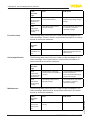
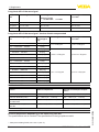
The following reset functions are available:
Delivery status: Restoring the parameter settings at the time of
shipment from the factory incl. the order-specific settings. A user-programmable linearization curve as well as the measured value memory
will be deleted.
Basic settings: Resetting the parameter settings incl. special
parameters to the default values of the respective instrument. A programmed linearization curve as well as the measured value memory
is deleted.
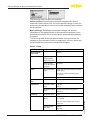
The following table shows the default values of the instrument. Depending on the instrument version or application, all menu items may
not be available or some may be differently assigned:
Reset - Setup
Menu item
Parameter
Application
Default value
Sensor
Measurement
loop name
Application process pressure
No reset
Slave for electronic differential
pressure
No reset
Unit of measurement
mbar (with nominal measuring range
≤400 mbar)
Temperature unit
°C
Application level
Units
0.00 bar
Position correction
Adjustment
bar (with nominal measuring ranges ≥1 bar)
Zero/Min. adjustment
0.00 bar
0.00 %
Span/Max. adjust- Nominal measuring range in bar
ment
100.00 %
Damping
Integration time
0.0 s
Current output
Current output Mode
Output characteristics
4 … 20 mA
≤ 3.6 mA
Current output Min./Max.
46
3.8 mA
20.5 mA
VEGABAR 82 • 4 … 20 mA/HART
45028-EN-131010
Reaction when malfunction occurs
6 Set up with the display and adjustment module
Menu item
Parameter
Default value
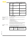
Released
Lock adjustment
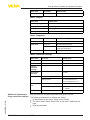
Reset - Display
Menu item
Default value
Menu language
Order-specific
Displayed value 1
Current output in %
Displayed value 2
Measuring cell temperature in °C
Backlight
Switched off
Reset - Diagnosis
Menu item
Parameter
Peak value
Default value
-
Sensor status
Pressure
Actual measured value
Temperature
Actual temperature values from measuring cell, electronics
Process pressure
Simulation
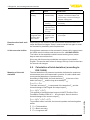
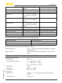
Reset - Additional settings
Menu item
Parameter
Default value
PIN
0000
Date/Time
Actual date/Actual time
Copy instrument
settings
No reset
Special parameters
Scaling
Current output
HART mode
Scaling size
Volume in l
Scaling format
0 % corresponds to 0 l
Current output - Size
Lin. percent - Level
Current output - adjustment
0 … 100 % correspond to
4 … 20 mA
100 % corresponds to 0 l
Address 0
45028-EN-131010
Additional adjustments - With this function the following device settings are copied.
Copy instrument settings The following parameters or settings are saved:
•
•
•
All parameters of the menu "Setup" and "Display"
The menu items "Reset, Date/Time" in the menu "Additional settings"
Special parameters
VEGABAR 82 • 4 … 20 mA/HART
47
6 Set up with the display and adjustment module
The copied data are permanently saved in the display and adjustment
module. They remain even in case of voltage loss.
Note:
Before the data are stored in the sensor, they are checked to make
sure they match the sensor. For this purpose, the sensor type of the
source data as well as the target sensor are displayed. Storing is only
carried out after release.
Additional adjustments Special parameters
In this menu item you gain access to the protected area where
you can enter special parameters. In exceptional cases, individual
parameters can be modified in order to adapt the sensor to special
requirements.
Change the settings of the special parameters only after having contacted our service staff.
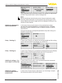
In menu item "Scaling" you define the scaling variable and the scaling
unit for the level value on the display, e.g. volume in l.
Setup - Scaling (2)
In menu item "Scaling (2)" you define the scaling format on the display
and the scaling of the measured level value for 0 % and 100 %.
Additional settings - Current output 1 and 2 (size)
In menu item"Current output, size" you determine which measured
value the current output refers to.
Additional settings Current output 1 and 2
(adjustment)
In menu item "Current output, adjustment" you can assign a respective measured value to the current output.
48
VEGABAR 82 • 4 … 20 mA/HART
45028-EN-131010
Setup - Scaling (1)
6 Set up with the display and adjustment module
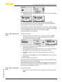
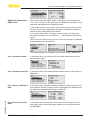
Additional adjustments HART mode
The sensor offers the HART modes "Analogue current output" and
"Fix current (4 mA)". In this menu item you determine the HART mode
and enter the address with Multidrop mode.
In the mode "Fixed current output" up to 63 sensors can be operated
on one two-wire cable (Multidrop operation). An address between 0
and 63 must be assigned to each sensor.
If you select the function "Analogue current output" and also enter
an address number, you can output a 4 … 20 mA signal in Multidrop
mode.
With the mode "Fixed current (4 mA)" a fixed 4 mA signal is outputted
independently of the actual level.
45028-EN-131010
The default setting is "Analogue current output" and the address 00.
Info - Instrument name
In this menu item, you read out the instrument name and the instrument serial number:
Info - Instrument version
In this menu item, the hardware and software version of the sensor is
displayed.
Info - Factory calibration
date
In this menu item, the date of factory calibration of the sensor as well
as the date of the last change of sensor parameters are displayed via
the display and adjustment module or via the PC.
Info - Sensor characteristics
In this menu item, the features of the sensor such as approval, process fitting, seal, measuring range, electronics, housing and others
are displayed.
VEGABAR 82 • 4 … 20 mA/HART
49
6 Set up with the display and adjustment module
6.5 Saving the parameter adjustment data
We recommended noting the adjusted data, e.g. in this operating
instructions manual, and archiving them afterwards. They are thus
available for multiple use or service purposes.
If the instrument is equipped with a display and adjustment module,
the data in the sensor can be saved in the display and adjustment
module. The procedure is described in the operating instructions
manual "Display and adjustment module" in the menu item "Copy
sensor data". The data remain there permanently even if the sensor
power supply fails.
The following data or settings for adjustment of the display and adjustment module are saved:
•
•
•
All data of the menu "Setup" and "Display"
In the menu "Additional adjustments" the items "Sensor-specific
units, temperature unit and linearization"
The values of the user programmable linearization curve
The function can also be used to transfer settings from one instrument to another instrument of the same type. If it is necessary to
exchange a sensor, the display and adjustment module is inserted
into the replacement instrument and the data are likewise written into
the sensor via the menu item "Copy sensor data".
45028-EN-131010
50
VEGABAR 82 • 4 … 20 mA/HART
7 Setup with PACTware
7 Setup with PACTware
7.1 Connect the PC
Via the interface adapter
directly on the sensor
2
1
3
Fig. 40: Connection of the PC directly to the sensor via the interface adapter
1 USB cable to the PC
2 Interface adapter VEGACONNECT
3 Sensor
Via the interface adapter
and HART
2
4
USB
N
OPE
3
TWIST
LO
CK
1
5
Fig. 41: Connecting the PC via HART to the signal cable
45028-EN-131010
1
2
3
4
5
Sensor
HART resistance 250 Ω (optional depending on processing)
Connection cable with 2 mm pins and terminals
Processing system/PLC/Voltage supply
Interface adapter, for example VEGACONNECT 4
Note:
With power supply units with integrated HART resistance (internal
resistance approx. 250 Ω), an additional external resistance is not
necessary. This applies, e.g. to the VEGA instruments VEGATRENN
149A, VEGAMET 381, VEGAMET 391. Common Ex separators are
also usually equipped with a sufficient current limitation resistance. In
such cases, the interface converter can be connected parallel to the
4 … 20 mA cable (dashed line in the previous illustration).
VEGABAR 82 • 4 … 20 mA/HART
51
7 Setup with PACTware
Prerequisites
7.2 Parameter adjustment
For parameter adjustment of the sensor via a Windows PC, the configuration software PACTware and a suitable instrument driver (DTM)
according to FDT standard are required. The up-to-date PACTware
version as well as all available DTMs are compiled in a DTM Collection. The DTMs can also be integrated into other frame applications
according to FDT standard.
Note:
To ensure that all instrument functions are supported, you should
always use the latest DTM Collection. Furthermore, not all described
functions are included in older firmware versions. You can download
the latest instrument software from our homepage. A description of
the update procedure is also available in the Internet.
Further setup steps are described in the operating instructions manual "DTM Collection/PACTware" attached to each DTM Collection and
which can also be downloaded from the Internet. Detailed descriptions are available in the online help of PACTware and the DTMs.
Fig. 42: Example of a DTM view
Standard/Full version
In the full version there is also an extended print function for complete
project documentation as well as a save function for measured value
and echo curves. In addition, there is a tank calculation program as
well as a multiviewer for display and analysis of the saved measured
value and echo curves.
52
VEGABAR 82 • 4 … 20 mA/HART
45028-EN-131010
All device DTMs are available as a free-of-charge standard version
and as a full version that must be purchased. In the standard version,
all functions for complete setup are already included. An assistant for
simple project configuration simplifies the adjustment considerably.
Saving/printing the project as well as import/export functions are also
part of the standard version.
7 Setup with PACTware
The standard version is available as a download under
www.vega.com/downloads and "Software". The full version is available on CD from the agency serving you.
7.3 Saving the parameter adjustment data
45028-EN-131010
We recommend documenting or saving the parameter adjustment
data via PACTware. That way the data are available for multiple use or
service purposes.
VEGABAR 82 • 4 … 20 mA/HART
53
8 Set up with other systems
8 Set up with other systems
8.1 DD adjustment programs
Device descriptions as Enhanced Device Description (EDD) are
available for DD adjustment programs such as, for example, AMS™
and PDM.
The files can be downloaded at www.vega.com/downloads under
"Software".
8.2 Field Communicator 375, 475
Device descriptions for the instrument are available as EDD for parameter adjustment with the Field Communicator 375 or 475.
45028-EN-131010
54
VEGABAR 82 • 4 … 20 mA/HART
9 Diagnosis, asset management and service
9 Diagnosis, asset management and service
Maintenance
9.1Maintenance
If the instrument is used properly, no special maintenance is required
in normal operation.
In some applications, product buildup on the diaphragm can influence
the measuring result. Depending on the sensor and application, take
precautions to ensure that heavy buildup, and especially a hardening
thereof, is avoided.
9.2 Diagnosis memory
The instrument has several memories which are available for diagnosis purposes. The data remain even with voltage interruption.
Measured value memory
Up to 60,000 measured values can be stored in the sensor in a ring
memory. Each entry contains date/time as well as the respective
measured value. Storable values are for example:
•
•
•
•
•
•
•
•
•
•
•
Pressure
Differential pressure
Level
Flow
Density
Interface
Percentage value
Lin. percent
Scaled values
Measuring cell temperature
Electronics temperature
When the instrument is shipped, the measured value memory is
active, saving distance, measurement certainty and electronics temperature every minute.
The requested values and recording conditions are set via a PC with
PACTware/DTM or the control system with EDD. Data are thus read
out and also reset.
Event memory
Up to 500 events are automatically stored with a time stamp in the
sensor (non-deletable). Each entry contains date/time, event type,
event description and value. Event types are for example:
45028-EN-131010
•
•
•
•
Modification of a parameter
Switch-on and switch-off times
Status messages (according to NE 107)
Error messages (according to NE 107)
The data are read out via a PC with PACTware/DTM or the control
system with EDD.
9.3 Asset Management function
The instrument features self-monitoring and diagnostics according
to NE 107 and VDI/VDE 2650. In addition to the status messages in
VEGABAR 82 • 4 … 20 mA/HART
55
9 Diagnosis, asset management and service
the following tables there are more detailed error messages available
under the menu item "Diagnostics" via the display and adjustment
module, PACTware/DTM and EDD.
Status messages
The status messages are divided into the following categories:
•
•
•
•
Failure
Function check
Out of specification
Maintenance requirement
and explained by pictographs:
1
2
3
4
Fig. 43: Pictographs of the status messages
1
2
3
4
Failure - red
Out of specification - yellow
Function check - orange
Maintenance - blue
Failure: Due to a malfunction in the instrument, a failure message is
outputted.
This status message is always active. It cannot be deactivated by the
user.
Function check: The instrument is in operation, the measured value
is temporarily invalid (for example during simulation).
This status message is inactive by default. It can be activated by the
user via PACTware/DTM or EDD.
Out of specification: The measured value is unstable because the
instrument specification is exceeded (e.g. electronics temperature).
This status message is inactive by default. It can be activated by the
user via PACTware/DTM or EDD.
Maintenance: Due to external influences, the instrument function
is limited. The measurement is affected, but the measured value is
still valid. Plan in maintenance for the instrument because a failure is
expected in the near future (e.g. due to buildup).
This status message is inactive by default. It can be activated by the
user via PACTware/DTM or EDD.
Failure
The following table shows the error codes in the status message
"Failure" and gives information on the reason and rectification. Keep
in mind that some information is only valid with four-wire instruments.
45028-EN-131010
56
VEGABAR 82 • 4 … 20 mA/HART
9 Diagnosis, asset management and service
Code
Cause
Rectification
F013
–– No valid measured value
available
–– Gauge pressure or low
pressure, measuring cell
defective
F017
–– Adjustment not within
specification
–– Change the adjustment
according to the limit values
F025
–– Index markers are not continuously rising, for examle
unlogical value pairs
–– Check linearization table
–– Delete table/Create new
F036
–– Failed or interrupted software update
–– Repeat software update
–– Check electronics version
–– Exchanging the electronics
–– Send instrument for repair
F040
–– Hardware defect
–– Exchanging the electronics
–– Send instrument for repair
F041
Error in the
electronics
–– No connection to the sensor –– Check connection to the
electronics
sensor electronics (with
detachable version)
F080
–– General software error
–– Separate operating voltage
briefly
F113
–– EMC interference
–– Remove EMC influences
F125
–– Temperature of the electronics in the non-specified
section
–– Check ambient temperature
–– Isolate electronics
–– Use instrument with higher
temperature range
F260
–– Error in the calibration carried out in the factory
–– Error in the EEPROM
–– Exchanging the electronics
–– Send instrument for repair
F261
–– Error during setup
–– Error when carrying out a
reset
–– Repeat setup
–– Repeat reset
Text message
no measured
value available
Adjustment
span too small
Error in the
linearization
table
no operable
sensor software
Error in the
electronics
Communication error,
display and
adjustment
module
Adjustment
software
PACTware out
of order
Unpermissible electronics
temperature
45028-EN-131010
Error in the
calibration
Error in the
configuration
VEGABAR 82 • 4 … 20 mA/HART
57
9 Diagnosis, asset management and service
Code
Cause
Rectification
F265
–– Sensor no longer carries
out a measurement
–– Carry out a reset
–– Separate operating voltage
briefly
F266
–– Operating voltage below
specified range
–– Check electrical connection
–– if necessary, increase
operating voltage
Text message
Measurement
function disturbed
Impermissible operating
voltage
Function check
The following table shows the error codes and text messages in the
status message "Function check" and provides information on causes
as well as corrective measures.
Code
Cause
Rectification
C700
–– A simulation is active
–– Finish simulation
–– Wait for the automatic end
after 60 mins.
Text message
Simulation active
Out of specification
The following table shows the error codes and text messages in the
status message "Out of specification" and provides information on
causes as well as corrective measures.
Code
Cause
Rectification
S600
–– Temperature of the electronics in the non-specified
section
–– Check ambient temperature
–– Isolate electronics
–– Use instrument with higher
temperature range
S603
–– Operating voltage below
specified range
–– Check electrical connection
–– if necessary, increase
operating voltage
Text message
Unpermissible electronics
temperature
Impermissible operating
voltage
Maintenance
The following table shows the error codes and text messages in the
status message "Maintenance" and provides information on causes
as well as corrective measures.
Cause
Rectification
M500
–– Stored delivery status is
wrong
–– Send instrument for repair
Text message
Error in the
delivery status
58
VEGABAR 82 • 4 … 20 mA/HART
45028-EN-131010
Code
9 Diagnosis, asset management and service
Code
Cause
Rectification
M501
–– Index markers are not continuously rising, for examle
unlogical value pairs
–– Check linearization table
–– Delete table/Create new
M502
–– Hardware error EEPROM
–– Exchanging the electronics
–– Send instrument for repair
M504
–– Hardware defect
–– Check connections
–– Exchanging the electronics
–– Send instrument for repair
M507
–– Error during setup
–– Error when carrying out a
reset
–– Carry out reset and repeat
setup
Text message
Error in the
non-active
linearization
table
Error in the
event memory
Error on an
device interface
Error in the
instrument
settings
9.4 Rectify faults
Reaction when malfunctions occur
The operator of the system is responsible for taking suitable measures to rectify faults.
Procedure for fault rectification
The first measures are:
•
•
•
Evaluation of fault messages, for example via the display and
adjustment module
Checking the output signal
Treatment of measurement errors
Further comprehensive diagnostics options offer a PC with the software PACTware and the suitable DTM. In many cases, the reasons
can be determined in this way and faults can be rectified.
Check the 4 … 20 mA
signal
Connect a multimeter in the suitable measuring range according to
the wiring plan. The following table describes possible errors in the
current signal and helps to remove them:
Error
Cause
Rectification
–– Set damping according to the
instrument via the display and
adjustment module or PACTware/
DTM
45028-EN-131010
4 … 20 mA signal –– Fluctuations of
not stable
the measured
variable
VEGABAR 82 • 4 … 20 mA/HART
59
9 Diagnosis, asset management and service
Error
Cause
Rectification
4 … 20 mA signal –– Electrical conmissing
nection faulty
–– Check connection according to
chapter "Connection steps" and
if necessary, correct according to
chapter "Wiring plan"
–– Voltage supply
missing
–– Check cables for breaks; repair if
necessary
–– Operating voltage too low or
load resistance
too high
–– Check, adapt if necessary
–– Electronics
module in the
sensor defective
–– Exchange the instrument or send it
in for repair
Current signal greater than
22 mA or less
than 3.6 mA
Reaction after fault rectification
Depending on the reason for the fault and the measures taken, the
steps described in chapter "Setup" must be carried out again or must
be checked for plausibility and completeness.
24 hour service hotline
Should these measures not be successful, please call in urgent cases
the VEGA service hotline under the phone no. +49 1805 858550.
The hotline is also available outside normal working hours, seven
days a week around the clock.
Since we offer this service worldwide, the support is provided in
English. The service itself is free of charge, the only costs involved are
the normal call charges.
Meaning of the total
deviation
9.5 Calculation of total deviation (according to
DIN 16086)
The total deviation of a pressure transmitter indicates the maximum
measurement error to be expected in practice. It is also called maximum practical deviation or operational error.
According to DIN 16086, the total deviation Ftotal is the sum of the
basic accuracy Fperf and the long-term stability Fstab:
Ftotal= Fperf + Fstab
The basic accuracy Fperf is composed of the deviation FKl and the
thermal change of zero signal and output span FT:
Fperf = √((FT)2 + (FKl)2)
This applies to the digital signal output via HART, Profibus PA or
Foundation Fieldbus. With a 4 … 20 mA output, there is also the
thermal change of the current output Fa:
To provide a better overview, the formula symbols are listed together
below:
•
•
•
60
Ftotal: Total deviation
Fperf: Basic accuracy
Fstab: Long-term drift
VEGABAR 82 • 4 … 20 mA/HART
45028-EN-131010
Fperf = √((FT)2 + (FKl)2 + (Fa)2)
9 Diagnosis, asset management and service
•
•
•
FT: Thermal change of zero signal and output span
FKl: Deviation
Fa: Thermal change of the current output
You can find the specifications in chapter "Technical data".
Practical example
Pressure measurement in the pipeline 8 bar (800 KPa)
Product temperature up to 50 °C
VEGABAR 82 with measuring range 10 bar, deviation < 0.075 %
Calculation of the turn down: TD = 10 bar/8 bar, TD = 1.25
Calculation - Digital output signal
1. step: Calculation of the basic accuracy
Fperf = √((FT)2 + (FKl)2)
FT = (0.15 %) x (0.5 + 0.5 x TD)
FKl= 0.075 %
Fperf = √((0.15 %) x (0.5 + 0.5 x TD)2 + (0.075 %)2)
Fperf = 0.19 %
Step 2: Calculation of the total deviation
Ftotal = Fperf + Fstab
Fstab = (0.05 % x TD)
Fstab = (0.05 % x 1.25)
Fstab = 0.06 %
Ftotal = 0.19 % + 0.063 % = 0.25 %
Calculation - Analogue
output signal
1. step: Calculation of the basic accuracy
Fperf = √((FT)2 + (FKl)2 + (Fa)2)
FT = (0.15 %) x (0.5 + 0.5 x TD)
FKl= 0.075 %
Fa = 0.15 %
Fperf = √((0.15 %) x (0.5 + 0.5 x TD)2 + (0.075 %)2) + (0.15 %)2)
Fperf = 0.24 %
Step 2: Calculation of the total deviation
Ftotal = Fperf + Fstab
Fstab = (0.05 % x TD)
Fstab = (0.05 % x 1.25)
Fstab = 0.06 %
45028-EN-131010
Ftotal = 0.24 % + 0.06 % = 0.30 %
9.6 Exchange process assembly with version
IP 68 (25 bar)
With version IP 68 (25 bar), the user can exchange the process assembly on site. Connection cable and external housing can be kept.
Required tools:
•
Hexagon socket wrench, size 2
VEGABAR 82 • 4 … 20 mA/HART
61
9 Diagnosis, asset management and service
Caution:
The exchange may only be carried out in the complete absence of
line voltage.
In Ex applications, only a replacement part with appropriate Ex approval may be used.
Proceed as follows when carrying out the exchange:
1. Losen the fixing screw with the hexagon socket wrench
2. Carefully detach the cable assembly from the process assembly
3
5
4
2
1
Fig. 44: VEGABAR 82 in IP 68 version, 25 bar and lateral cable outlet, external
housing
1
2
3
4
5
Process assembly
Plug connector
Cable assembly
Connection cable
External housing
3. Loosen the plug connector
4. Mount the new process assembly on the measuring point
5. Plug the connector back in
6. Mount the cable assembly on the process assembly and turn it to
the desired position
7. Tighten the fixing screw with the hexagon socket wrench
The exchange is finished.
If there is no replacement part available on site, one can be ordered
from the agency serving you.
The necessary serial number can be found on the type label of the
instrument or on the delivery note.
In case of a defect, the user can replace the electronics module with
another one of identical type.
62
VEGABAR 82 • 4 … 20 mA/HART
45028-EN-131010
9.7 Exchanging the electronics module
9 Diagnosis, asset management and service
In Ex applications, only instruments and electronics modules with appropriate Ex approval may be used.
If there is no electronics module available on site, one can be ordered
from the agency serving you.
Ordering and exchange are possible with or without sensor serial
number. The electronics module with serial number includes orderspecific data such as factory setting, seal material etc. These are not
included in the electronics module without serial number.
The serial number is stated on the type label of VEGABAR 82 or on
the delivery note.
You can find detailed information on the electronics exchange in the
booklet "Operating instructions for electronics module VEGABAR
series 80".
9.8 Software update
The following components are required to update the sensor software:
•
•
•
•
•
Sensor
Voltage supply
Interface adapter VEGACONNECT
PC with PACTware
Current sensor software as file
You can find the actual sensor software as well as detailed information of the procedure under "www.vega.com/downloads" and
"Software".
You can find information about the installation in the download file.
Caution:
Instruments with approvals can be bound to certain software versions. Therefore make sure that the approval remains effective with a
software update.
You can find detailed information on www.vega.com/downloads and
"Approvals".
9.9 How to proceed in case of repair
You can find a repair form as well as detailed information on how to
proceed under www.vega.com/downloads and "Forms and certificates".
By doing this you help us carry out the repair quickly and without having to call back for needed information.
45028-EN-131010
If a repair is necessary, please proceed as follows:
•
•
•
•
Print and fill out one form per instrument
Clean the instrument and pack it damage-proof
Attach the completed form and, if need be, also a safety data
sheet outside on the packaging
Please contact the agency serving you to get the address for
the return shipment. You can find the agency on our home page
www.vega.com.
VEGABAR 82 • 4 … 20 mA/HART
63
10 Dismounting
10Dismounting
10.1 Dismounting steps
Warning:
Before dismounting, be aware of dangerous process conditions such
as e.g. pressure in the vessel or pipeline, high temperatures, corrosive or toxic products etc.
Take note of chapters "Mounting" and "Connecting to power supply"
and carry out the listed steps in reverse order.
10.2Disposal
The instrument consists of materials which can be recycled by specialised recycling companies. We use recyclable materials and have
designed the parts to be easily separable.
Correct disposal avoids negative effects on humans and the environment and ensures recycling of useful raw materials.
Materials: see chapter "Technical data"
If you have no way to dispose of the old instrument properly, please
contact us concerning return and disposal.
WEEE directive 2002/96/EG
This instrument is not subject to the WEEE directive 2002/96/EG and
the respective national laws. Pass the instrument directly on to a specialised recycling company and do not use the municipal collecting
points. These may be used only for privately used products according
to the WEEE directive.
45028-EN-131010
64
VEGABAR 82 • 4 … 20 mA/HART
11 Supplement
11Supplement
11.1 Technical data
Materials and weights
Materials, wetted parts
Process fitting
Diaphragm
Joining material diaphragm/Basic element measuring cell
Measuring cell seal
316L, PVDF, Alloy C-22, Alloy C-276, Duplex 1.4462,
Titanium Grade 2
Sapphire-ceramic® (> 99.9 % Al2O3 ceramic)
Glass (with double and form seal, non-wetted parts)
FKM (VP2/A, A+P 70.16), EPDM (A+P 75.5/KW75F),
FFKM (Kalrez 6375, Perlast G75S, Perlast G75B)
Seal for process fitting (in the scope of delivery)
ƲƲ Thread G½ (EN 837)
Klingersil C-4400
ƲƲ M44 x 1.25 (DIN 13), M30 x 1.5
FKM, FFKM, EPDM
ƲƲ Thread G1½ (DIN 3852-A)
Klingersil C-4400
Materials for applications in foodstuffs
Surface quality hygienic fittings, typ.
Seal below wall mounting plage 316L
with 3A approval
Materials, non-wetted parts
Electronics housing
External housing
Socket, wall mounting plate external
housing
EPDM
Plastic PBT (polyester), Alu die-casting powder-coated,
316L
plastic PBT (Polyester), 316L
plastic PBT (Polyester), 316L
Seal between base and wall mounting
plate
EPDM (fixed connected)
Inspection window in housing cover for
display and adjustment module
Polycarbonate (UL-746-C listed)
Seal, housing cover
NBR (stainless steel housing), silicone (Alu/plastic housing)
Ground terminal
316Ti/316L
Type label support on connection cable
PE hard
Connection cable between transmitter
and external electronics housing with
IP 68 (25 bar) version
Connection cable with IP 68 (1 bar)
version
45028-EN-131010
Ra < 0.8 µm
Weights
Total weight VEGABAR 82 approx.
VEGABAR 82 • 4 … 20 mA/HART
PE, PUR
PE
0.8 … 8 kg (1.764 … 17.64 lbs), depending on process
fitting and housing
65
11 Supplement
Input variable
Adjustment
Adjustment range of the min./max. adjustment relating to the nominal measuring range:
ƲƲ Percentage value
ƲƲ Pressure value
-10 … 110 %
-20 … 120 %
Adjustment range of the zero/span adjustment relating to the nominal measuring range:
ƲƲ zero
-20 … +95 %
ƲƲ Difference between zero and span
max. 120 % of the nominal range
ƲƲ span
Recommended max. turn down
-120 … +120 %1)
20 : 1 (no limitation)
Nominal measuring ranges and overload capability in bar/kPa
The specifications are only an overview and refer to the measuring cell. Limitations due to the
material and version of the process fitting as well as the selected pressure type are possible. The
specifications on the nameplate apply.
Nominal range
Overload capacity, max.
pressure
Overload capacity, min. pressure
0 … +0.025 bar/0 … +2.5 kPa
+5 bar/+500 kPa
-0.05 bar/-5 kPa
0 … +0.1 bar/0 … +10 kPa
+15 bar/+1500 kPa
-0.2 bar/-20 kPa
0 … +0.4 bar/0 … +40 kPa
+30 bar/+3000 kPa
-0.8 bar/-80 kPa
0 … +1 bar/0 … +100 kPa
+35 bar/+3500 kPa
-1 bar/-100 kPa
0 … +2.5 bar/0 … +250 kPa
+50 bar/+5000 kPa
-1 bar/-100 kPa
0 … +10 bar/0 … +1000 kPa
+90 bar/+9000 kPa
-1 bar/-100 kPa
0 … +25 bar/0 … +2500 kPa
+130 bar/+13000 kPa
-1 bar/-100 kPa
0 … +60 bar/0 … +6000 kPa
+200 bar/+20000 kPa
-1 bar/-100 kPa
0 … +100 bar/0 … +10000 kPa
+200 bar/+20000 kPa
-1 bar/-100 kPa
-1 … 0 bar/-100 … 0 kPa
+35 bar/+3500 kPa
-1 bar/-100 kPa
-1 … +1.5 bar/-100 … +150 kPa
+40 bar/+4000 kPa
-1 bar/-100 kPa
-1 … +10 bar/-100 … +1000 kPa
+90 bar/+9000 kPa
-1 bar/-100 kPa
-1 … +25 bar/-100 … +2500 kPa
+130 bar/+13000 kPa
-1 bar/-100 kPa
-1 … +60 bar/-100 … +6000 kPa
+200 bar/+20000 kPa
-1 bar/-100 kPa
-1 … +100 bar/-100 … +10000 kPa
+200 bar/+20000 kPa
-1 bar/-100 kPa
-0.05 … +0.05 bar/-5 … +5 kPa
+15 bar/+1500 kPa
-0.2 bar/-20 kPa
-0.2 … +0.2 bar/-20 … +20 kPa
+20 bar/+2000 kPa
-0.4 bar/-40 kPa
-0.5 … +0.5 bar/-50 … +50 kPa
+35 bar/+3500 kPa
-1 bar/-100 kPa
Gauge pressure
(only for measuring cell ø 28 mm)
(only for measuring cell ø 17.5 mm)
(only for measuring cell ø 17.5 mm)
1)
Values less than -1 bar cannot be set.
66
VEGABAR 82 • 4 … 20 mA/HART
45028-EN-131010
Absolute pressure
11 Supplement
Nominal range
Overload capacity, max.
pressure
Overload capacity, min. pressure
0 … 0.1 bar/0 … 10 kPa
15 bar/1500 kPa
0.8 bar abs.
0 … 1 bar/0 … 100 kPa
35 bar/3500 kPa
0 bar abs.
0 … 2.5 bar/0 … 250 kPa
50 bar/5000 kPa
0 bar abs.
0 … 10 bar/0 … 1000 kPa
90 bar/9000 kPa
0 bar abs.
0 … 25 bar/0 … 2500 kPa
130 bar/13000 kPa
0 bar abs.
0 … 60 bar/0 … 6000 kPa
200 bar/20000 kPa
0 bar abs.
0 … +100 bar/0 … +10000 kPa
200 bar/20000 kPa
0 bar abs.
(only for measuring cell 17.5 mm)
Nominal measuring ranges and overload capacity in psi
The specifications are only an overview and refer to the measuring cell. Limitations due to the
material and version of the process fitting as well as the selected pressure type are possible. The
specifications on the nameplate apply.
Nominal range
Overload capacity, max.
pressure
Overload capacity, min. pressure
0 … +0.4 psig
+75 psig
-0.725 psig
0 … +1.5 psig
+225 psig
-2.901 psig
0 … +5 psig
+435 psig
-11.60 psig
0 … +15 psig
+510 psig
-14.51 psig
0 … +30 psig
+725 psig
-14.51 psig
0 … +150 psig
+1300 psig
-14.51 psig
0 … +300 psig
+1900 psig
-14.51 psig
0 … +900 psig
+2900 psig
-14.51 psig
0 … +1500 psig
+2900 psig
-14.51 psig
-14.5 … 0 psig
+510 psig
-14.51 psig
-14.5 … +20 psig
+580 psig
-14.51 psig
-14.5 … +150 psig
+1300 psig
-14.51 psig
-14.5 … +300 psig
+1900 psig
-14.51 psig
-14.5 … +900 psig
+2900 psig
-14.51 psig
-14.5 … +1500 psig
+2900 psig
-14.51 psig
-0.7 … +0.7 psig
+225 psig
-2.901 psig
-3 … +3 psig
+290 psi
-5.800 psig
-7 … +7 psig
+510 psig
-14.51 psig
225 psig
0 psi
Gauge pressure
(only for measuring cell ø 28 mm)
(only for measuring cell ø 17.5 mm)
45028-EN-131010
(only for measuring cell ø 17.5 mm)
Absolute pressure
0 … 1.5 psi
VEGABAR 82 • 4 … 20 mA/HART
67
11 Supplement
Nominal range
Overload capacity, max.
pressure
Overload capacity, min. pressure
0 … 5 psi
435 psi
0 psi
0 … 15 psi
510 psi
0 psi
0 … 30 psi
725 psi
0 psi
0 … 150 psi
1300 psi
0 psi
0 … 300 psi
1900 psi
0 psi
0 … 900 psi
2900 psi
0 psi
0 … +1450 psig
2900 psig
0 psi
(only for measuring cell 17.5 mm)
Output variable
For details on the operating voltage see chapter "Voltage supply"
Output signal
4 … 20 mA/HART
Fulfilled HART specification
7.3
Range of the output signal
Signal resolution
Failure signal current output (adjustable)
3.8 … 20.5 mA/HART (default setting)
0.3 µA
≥ 21 mA, ≤ 3.6 mA, last valid measured value
Max. output current
21.5 mA
Load
Load resistor, see chapter "Voltage supply"
Starting current
Damping (63 % of the input variable),
adjustable
≤ 10 mA for 5 ms after switching on, ≤ 3.6 mA
0 … 999 s
HART output values according to HART 7 (default setting)2)
ƲƲ First HART value (PV)
Linear percentage value
ƲƲ Third HART value (TV)
Measuring cell temperature
ƲƲ Second HART value (SV)
ƲƲ Fourth HART value (QV)
Physical unit of the application
Electronics temperature
Output variable - Second current output
For details on the operating voltage see chapter "Voltage supply"
Output signal
4 … 20 mA (passive)
Signal resolution
0.3 µA
Range of the output signal
3.8 … 20.5 mA (default setting)
Failure signal current output (adjustable) Last valid measured value, ≥ 21 mA, ≤ 3.6 mA
Max. output current
21.5 mA
Load
Load resistor, see chapter "Voltage supply"
Starting current
2)
0 … 999 s
The output values can be assigned individually
68
VEGABAR 82 • 4 … 20 mA/HART
45028-EN-131010
Damping (63 % of the input variable),
adjustable
≤ 10 mA for 5 ms after switching on, ≤ 3.6 mA
11 Supplement
Dynamic behaviour output
Run-up time approx.
10 s
Dynamic characteristics, depending on medium, temperature and, if applicable, chemical seal
100 %
90 %
2
1
10 %
tT
tS
tA
t
Fig. 45: Behaviour in case of sudden change of the process variable. tT: dead time; tA: rise time; tS: jump response
time
1
2
Process variable
Output signal
Dead time
> 45 ms
Step response time
> 80 ms (ti: 0 s, 10 … 90 %)
Rise time
Damping (63 % of the input variable)
> 35 ms (10 … 90 %)
0 … 999 s, adjustable
Additional output parameter - temperature
Processing is made via output signal HART multidrop, Profibus PA and Foundation Fieldbus
Range
Resolution
Accuracy
ƲƲ in the range of 0 … +100 °C
(+32 … +212 °F)
ƲƲ In the range of -60 … 0 °C
(-76 … +32 °F) and +100 … +150 °C
(+212 … +302 °F)
-60 … +150 °C (-76 … +302 °F)
< 0.2 K
±2 K
typ. ±4 K
Reference conditions and actuating variables (according to DIN EN 60770-1)
Reference conditions according to DIN EN 61298-1
ƲƲ Temperature
+15 … +25 °C (+59 … +77 °F)
ƲƲ Air pressure
860 … 1060 mbar/86 … 106 kPa (12.5 … 15.4 psig)
45028-EN-131010
ƲƲ Relative humidity
Determination of characteristics
Characterstic curve
Reference installation position
Influence of the installation position
VEGABAR 82 • 4 … 20 mA/HART
45 … 75 %
Limit point adjustment according to IEC 61298-2
Linear
upright, diaphragm points downward
< 0.2 mbar/20 Pa (0.003 psig)
69
11 Supplement
Deviation (according to IEC 60770)
Applies to the digital signal output (HART, Profibus PA, Foundation Fieldbus) as well as to the
analogue current output 4 … 20 mA and refers to the set span. Turn down (TD) is the ratio nominal
measuring range/set span.
The specified values correspond to the value FKl in chapter "Calculation of the total deviation".
Accuracy class
Non-linearity, hysteresis and re- Non-linearity, hysteresis and repeatability with TD 1 : 1 up to 5 : 1 peatability with 5 : 1
0.05 %
< 0.05 %
< 0.01 % x TD
0.1 %
< 0.1 %
< 0.02 % x TD
0.2 %
< 0.2 %
< 0.04 % x TD
Influence of the product or ambient temperature
Thermal change zero signal and output span
Applies to the digital signal output (HART, Profibus PA, Foundation Fieldbus) as well as to the
analogue current output 4 … 20 mA and refers to the set span. Turn down (TD) is the ratio nominal
measuring range/set span.
The thermal change of zero signal and output span corresponds to the value FT in chapter "Calculation of the total deviation (according to DIN 16086)".
Measuring cell - Standard
Medium or ambient tem- Accuracy class 0.05 %,
perature T
0.1 %
Accuracy class 0.2 %
Accuracy class 0.2 %
with measuring range
0.1 barabs
-40 … 0 °C (-40 … +32 °F) < {0.15 % + 0.015 %/K x (- < {0.1 % + 0.03 %/K x (-T)} < {0.30 % + 0.03 %/K x (T)} x {0.5+0.5 x TD}
x {0.5+0.5 x TD}
T)} x {0.5+0.5 x TD}
0 … 40 °C
(+32 … +104 °F)
< {0.0075 %/K x (T 20 °C)} x {0.5+0.5 x TD}
< {0.005 %/K x (T - 20 °C)} < {0.015 %/K x (T - 20 °C)}
x {0.5+0.5 x TD}
x {0.5+0.5 x TD}
40 … 100 °C
(+104 … +212 °F)
< {0.15 % } x {0.5+0.5 x
TD}
< {0.005 %/K x (T - 20 °C)}
< {0.3 % } x {0.5+0.5 x TD}
x {0.5+0.5 x TD}
100 … 120 °C
(+212 … +248 °F)
< {0.15 % + 0.005 %/K x (T < {0.40 % + 0.01 %/K x (T - < {0.30 % + 0.01 %/K x (T - 100 °C)} x {0.5+0.5 x TD} 100 °C)} x {0.5+0.5 x TD} 100 °C)} x {0.5+0.5 x TD}
Measuring cell - climate-compensated
Compensated temperature range
Non-compensated temperature range
0 … +100 °C (+32 … +212 °F)
-40 … 0 °C (-40 … +32 °F), -100 … +130 °C
(+212 … +276 °F)
45028-EN-131010
70
VEGABAR 82 • 4 … 20 mA/HART
11 Supplement
Nominal measuring range in bar/
kPa
Nominal measuring
range in psig
0 … 10 bar/0 … 1000 kPa
0 … 150 psig
0 … 25 bar/0 … 2500 kPa
0 … 350 psig
0 … 60 bar/0 … 6000 kPa
0 … 900 psig
0 … 100 bar/0 … 10000 kPa
0 … 1450 psig
-1 … 0 bar/-100 … 0 kPa
-15 … 0 psig
-1 … 1.5 bar/-100 … 150 kPa
-15 … 25 psig
-1 … 10 bar/-100 … 1000 kPa
-15 … 150 psig
-1 … 25 bar/-100 … 2500 kPa
-15 … 350 psig
-1 … 60 bar/-100 … 6000 kPa
-15 … 900 psig
-1 … 100 bar/-100 … 10000 kPa
-15 … 1450 psig
0 … 1 bar/0 … 100 kPa
0 … 15 psig
0 … 2.5 bar/0 … 250 kPa
0 … 35 psig
-0.5 … 0.5 bar/-50 … 50 kPa
-7 … 7 psig
-0.2 … 0.2 bar/-20 … 20 kPa
-3 … 3 psig
0 … 0.4 bar/0 … 40 kPa
0 … 6 psig
In the compensated
temperature range
In the non-compensated temperature
range
< {0.05 % + 0.1 x
(0.5+0.5 x TD)}
< {0.1 % + 0.15 x
(0.5+0.5 x TD)}
< {0.1 % + 0.2 x
(0.5+0.5 x TD)}
< {0.1 % + 0.3 x
(0.5+0.5 x TD)}
< {0.15 % + 0.4 x
(0.5+0.5 x TD)}
< {0.15 % + 0.6 x
(0.5+0.5 x TD)}
Thermal change, current output
Applies also to the analogue 4 … 20 mA current output and refers to the set span.
Thermal change, current output
< 0.05 %/10 K, max. < 0.15 %, each with -40 … +80 °C
(-40 … +176 °F)
The thermal change of the current output corresponds to the value Fa in chapter "Calculation of the
total deviation (according to DIN 16086)".
0,15 %
-40°C
-20°C
20°C
40°C
60°C
80°C
-0,15 %
45028-EN-131010
Fig. 46: Thermal change, current output
>>>Long-term stability (according to DIN 16086 and IEC 60770-1)
Applies to the digital signal output (HART, Profibus PA, Foundation Fieldbus) as well as to the
analogue current output 4 … 20 mA under reference conditions. The specifications refer to the set
span. Turn down (TD) is the ratio nominal measuring range/set span.
The long-term drift of the zero signal corresponds to the value FStab in chapter "Calculation of the
total deviation (according to DIN 16086)".
VEGABAR 82 • 4 … 20 mA/HART
71
11 Supplement
Long-term drift of the zero signal
Time period
Measuring cell ø 28 mm
Measuring cell ø 28 mm
Measuring cell
ø 17.5 mm
One year
< 0.05 % x TD
< 0.1 % x TD
< 0.1 % x TD
Five years
< 0.1 % x TD
< 0.2 % x TD
< 0.2 % x TD
Ten years
< 0.2 % x TD
< 0.4 % x TD
< 0.4 % x TD
Measuring range
0 … +0.025 bar/0 … +2.5 kPa
Long-term drift of the zero signal - Version climate-compensated
Nominal measuring range in bar/ Nominal measkPa
uring range in
psig
0 … 0.4 bar/0 … 40 kPa
0 … 6 psig
-0.2 … 0.2 bar/-20 … 20 kPa
-3 … 3 psig
0 … 1 bar/0 … 100 kPa
0 … 15 psig
0 … 2.5 bar/0 … 250 kPa
0 … 35 psig
-1 … 0 bar/-100 … 0 kPa
-15 … 0 psig
-1 … 1.5 bar/-100 … 150 kPa
-15 … 25 psig
-0.5 … 0.5 bar/-50 … 50 kPa
-7 … 7 psig
0 … 10 bar/0 … 1000 kPa
0 … 150 psig
0 … 25 bar/0 … 2500 kPa
0 … 350 psig
0 … 60 bar/0 … 6000 kPa
0 … 900 psig
0 … 100 bar/0 … 6000 kPa
0 … 1450 psig
-1 … 10 bar/-100 … 1000 kPa
-15 … 150 psig
-1 … 25 bar/-100 … 2500 kPa
-15 … 350 psig
-1 … 60 bar/-100 … 6000 kPa
-15 … 900 psig
Measuring cell ø 28 mm
Measuring cell
ø 17.5 mm
< (1 % x TD)/year
< (1.5 % x TD)/year
< (0.25 % x TD)/year
< (0.375 % x TD)/year
< (0.1 % x TD)/year
< (0.15 % x TD)/year
Ambient conditions
Version
Ambient temperature
Storage and transport temperature
Standard version
-40 … +80 °C (-40 … +176 °F)
-60 … +80 °C (-76 … +176 °F)
Version IP 66/IP 68 (1 bar)
-20 … +80 °C (-4 … +176 °F)
-20 … +80 °C (-4 … +176 °F)
Version IP 68 (25 bar) with connection cable PUR
-20 … +80 °C (-4 … +176 °F)
-20 … +80 °C (-4 … +176 °F)
Version IP 68 (25 bar), connection
cable PE
-20 … +60 °C (-4 … +140 °F)
-20 … +60 °C (-4 … +140 °F)
The specifications are an overview. The specification on the type plate are valid.
3)
With process fitting PVDF, max. 100 °C (212 °F).
72
VEGABAR 82 • 4 … 20 mA/HART
45028-EN-131010
Process conditions
Product temperature depending on the measuring cell seal3)
11 Supplement
Measuring cell seal
Product temperature - standard
version
Product temperature - version
with extended temperature range
FKM (VP2/A)
-20 … +130 °C (-4 … +266 °F)
-20 … +150 °C (-4 … +302 °F)
FKM (A+P 70.16)
-40 … +130 °C (-40 … +266 °F)
-
FKM (ET 7067)
-20 … +130 °C (-4 … +266 °F)
-
EPDM (A+P 75.5/KW75F)
-40 … +130 °C (-40 … +266 °F)
-40 … +150 °C (-40 … +302 °F)
EPDM (ET 7056)
-40 … +130 °C (-40 … +266 °F)
-
FFKM (Kalrez 6375)
-20 … +130 °C (-4 … +266 °F)
-20 … +150 °C (-4 … +302 °F)
FFKM (Perlast G75S)
-15 … +130 °C (-4 … +266 °F)
-15 … +150 °C (5 … +302 °F)
FFKM (Perlast G75B)
-15 … +130 °C (-4 … +266 °F)
-15 … +150 °C (5 … +302 °F)
FFKM (Chemraz 535)
-30 … +130 °C (-22 … +266 °F)
-
FEPM (Fluoraz SD890)
-5 … +130 °C (-22 … +266 °F)
-
1 h: 140 °C/284 °F cleaning temperature
1 h: 140 °C/284 °F cleaning temperature
1 h: 140 °C/284 °F cleaning temperature
Product temperature depending on the ambient temperature
Ambient temperature
Product temperature
+50 °C (+122 °F)
+150 °C (+302 °F)
+80 °C (+176 °F)
+100 °C (+212 °F)
Mechanical stress, depending on the instrument version
Vibration resistance
Shock resistance
4 g at 5 … 200 Hz according to EN 60068-2-6 (vibration
with resonance)
100 g, 6 ms according to EN 60068-2-27 (mechanical
shock)
Electromechanical data - version IP 66/IP 67 and IP 66/IP 68; 0.2 bar
Options of the cable entry
ƲƲ Cable gland
ƲƲ Cable diameter (options)
ƲƲ Cable entry
45028-EN-131010
ƲƲ Blind plug
ƲƲ Closing cap
Plug options
ƲƲ Signal circuit
ƲƲ Indication circuit
VEGABAR 82 • 4 … 20 mA/HART
M20 x 1.5
5 … 9 mm (0.20 … 0.35 in)
6 … 12 mm (0.24 … 0.47 in)
10 … 14 mm (0.39 … 0.55 in)
½ NPT
M20 x 1.5; ½ NPT
M20 x 1.5; ½ NPT
Plug M12 x 1, according to ISO 4400, Harting HAN,
7/8" FF
M12 x 1 plug
73
11 Supplement
Wire cross-section (spring-loaded terminals)
ƲƲ Massive wire, cord
ƲƲ Stranded wire with end sleeve
0.2 … 2.5 mm² (AWG 24 … 14)
0.2 … 1.5 mm² (AWG 24 … 16)
Electromechanical data - version IP 66/IP 68 (1 bar)
Connection cable
ƲƲ Configuration
ƲƲ Wire cross-section
ƲƲ Wire resistance
ƲƲ Tensile strength
ƲƲ Standard length
ƲƲ Max. length
ƲƲ Min. bending radius
ƲƲ Diameter approx.
ƲƲ Colour - Non-Ex version
ƲƲ Colour - Ex-version
four wires, one breather capillary, one suspension cable,
screen braiding, metal foil, mantle
0.5 mm² (AWG 20)
< 0.036 Ω/m
< 1200 N (270 lbf)
5 m (16.4 ft)
180 m (590.6 ft)
25 mm (0.984 in) with 25 °C (77 °F)
8 mm (0.315 in)
Black
Blue
Electromechanical data - version IP 68 (25 bar)
Connection cable between IP 68 instrument and external housing
ƲƲ Configuration
ƲƲ Wire cross-section
ƲƲ Wire resistance
ƲƲ Standard length
ƲƲ Max. length
ƲƲ Min. bending radius at 25 °C/77 °F
ƲƲ Diameter approx.
ƲƲ Colour
Cable entry/plug
4)
ƲƲ External housing
Spring-loaded terminals for wire crosssection up to
Measured value indication
ƲƲ Number of digits
4)
0.5 mm² (AWG 20)
< 0.036 Ω/m (0.011 Ω/ft)
5 m (16.40 ft)
180 m (590.5 ft)
25 mm (0.985 in)
8 mm (0.315 in)
Blue
–– 1 x cable gland M20 x 1.5 (cable: ø 5 … 9 mm), 1 x
blind plug M20 x 1.5
or:
–– 1␣x plug (depending on the version), 1␣x blind stopper
M20␣x␣1.5
2.5 mm² (AWG 14)
Display with backlight
5
Depending on the version M12 x 1, according to ISO 4400, Harting, 7/8" FF.
74
VEGABAR 82 • 4 … 20 mA/HART
45028-EN-131010
Display and adjustment module
Display element
four wires, one suspension wire, one breather capillary,
screen braiding, metal foil, mantle
11 Supplement
ƲƲ Size of digits
Adjustment elements
Protection rating
ƲƲ unassembled
ƲƲ mounted into the housing without
cover
Materials
ƲƲ Housing
ƲƲ Inspection window
W x H = 7 x 13 mm
4 keys
IP 20
IP 40
ABS
Polyester foil
Interface to the external display and adjustment unit
Data transmission
digital (I²C-Bus)
Configuration, connection cable
Cable length max.
ƲƲ Sensors with signal output
4 … 20 mA, 4 … 20 mA/HART
ƲƲ Sensors with signal output Profibus
PA, Foundation Fieldbus
4-wire, screened
50 m
25 m
Interface to the slave sensor
Data transmission
digital (I²C-Bus)
Cable length max.
25 m
Configuration, connection cable
4-wire, screened
Integrated clock
Date format
Day.Month.Year
Time zone Ex factory
CET
Time format
Rate deviation max.
12 h/24 h
10.5 min/year
Measurement electronics temerature
Resolution
1 °C (1.8 °F)
Accuracy
Voltage supply
Operating voltage UB
ƲƲ Non-Ex instrument
9.6 … 35 V DC
ƲƲ Ex-ia instrument
9.6 … 30 V DC
ƲƲ Ex-d instrument
45028-EN-131010
±1 °C (1.8 °F)
ƲƲ Ex-d-ia instrument
ƲƲ Ex-d-ia instrument with ship approval
Interpolation protection
9.6 … 35 V DC
15 … 35 V DC
15 … 35 V DC
Integrated
Permissible residual ripple - Non-Ex, Ex-ia instrument
VEGABAR 82 • 4 … 20 mA/HART
75
11 Supplement
ƲƲ for UN 12 V DC (9.6 V< UB < 14 V)
ƲƲ for UN 24 V DC (18 V< UB < 35 V)
≤ 0.7 Veff (16 … 400 Hz)
≤ 1.0 Veff (16 … 400 Hz)
Permissible residual ripple - Ex-d-ia instrument
ƲƲ for UN 24 V DC (18 V< UB < 35 V)
≤ 1 Veff (16 … 400 Hz)
ƲƲ Calculation
(UB - Umin)/0.022 A
Load resistor
ƲƲ Example - Non-Ex instrument with
UB= 24 V DC
(24 V - 9.6 V)/0.022 A = 655 Ω
Potential connections in the instrument
Electronics
Not non-floating
Ground terminal
Galvanically connected with the process fitting
Electrical protective measures
Housing material
Version
IP-protection class
NEMA protection
Plastic
Single chamber
IP 66/IP 67
NEMA 4X/6P
Double chamber
IP 66/IP 67
NEMA 4X
Single chamber
IP 66/IP 68 (0.2 bar)
NEMA 4X/6P
Double chamber
IP 66/IP 67
NEMA 4X
Single chamber
IP 69K
-
IP 66/IP 68 (0.2 bar)
NEMA 4X/6P
Double chamber
IP 66/IP 67
NEMA 4X
Transmitter for external
housing
IP 68 (25 bar)
-
Aluminium
Stainless steel, electropolished
IP 68 (1 bar)
IP 66/IP 68 (0.2 bar)
Single chamber
IP 66/IP 68 (0.2 bar)
Stainless steel, investment Single chamber
casting
Stainless steel
Overvoltage category
Protection class
IP 68 (1 bar)
IP 66/IP 68 (0.2 bar)
-
NEMA 4X
NEMA 4X/6P
NEMA 4X
NEMA 4X
III
II
Approvals
Instruments with approvals can have different technical data depending on the version.
For that reason the associated approval documents of these instruments must be carefully noted.
They are part of the delivery or can be downloaded under www.vega.com and "VEGA Tools" as
well as under "Downloads" and "Approvals".
The following dimensional drawings represent only an extract of the possible versions. Detailed
dimensional drawings can be downloaded at www.vega.com under "Downloads" and "Drawings".
76
VEGABAR 82 • 4 … 20 mA/HART
45028-EN-131010
11.2Dimensions
11 Supplement
Plastic housing
~ 69 mm
(2.72")
ø 79 mm
(3.11")
~ 84 mm
(3.31")
ø 79 mm
(3.11")
M20x1,5/
½ NPT
112 mm
(4.41")
112 mm
(4.41")
M16x1,5
M20x1,5/
½ NPT
1
2
Fig. 47: Housing versions in protection IP 66/IP 67 - with integrated display and adjustment module the housing is
9 mm/0.35 in higher
1
2
Single chamber version
Double chamber version
Aluminium housing
~ 116 mm
(4.57")
~ 87 mm
(3.43")
ø 86 mm
(3.39")
ø 86 mm
(3.39")
120 mm
(4.72")
116 mm
(4.57")
M16x1,5
M20x1,5
M20x1,5/
½ NPT
1
M20x1,5/
½ NPT
2
Fig. 48: Housing versions in protection IP 66/IP 67 - with integrated display and adjustment module the housing is
9 mm/0.35 in higher
Single chamber version
Double chamber version
45028-EN-131010
1
2
VEGABAR 82 • 4 … 20 mA/HART
77
11 Supplement
Aluminium housing in protection rating IP 66/IP 68 (1 bar)
~ 105 mm
(4.13")
~ 150 mm
(5.91")
ø 86 mm
(3.39")
ø 86 mm
(3.39")
120 mm
(4.72")
116 mm
(4.57")
M16x1,5
M20x1,5
M20x1,5
M20x1,5/
½ NPT
1
2
Fig. 49: Housing versions in protection IP␣66/IP␣68 (1␣bar) - with integrated display and adjustment module the
housing is 9␣mm/0.35␣in higher
1
2
Single chamber version
Double chamber version
Stainless steel housing
~ 87 mm
(3.43")
~ 69 mm
(2.72")
ø 79 mm
(3.11")
~ 59 mm
(2.32")
ø 80 mm
(3.15")
ø 86 mm
(3.39")
M20x1,5/
½ NPT
M20x1,5/
½ NPT
1
2
120 mm
(4.72")
112 mm
(4.41")
117 mm
(4.61")
M16x1,5
M20x1,5/
½ NPT
3
Fig. 50: Housing versions in protection IP 66/IP 67 - with integrated display and adjustment module the housing is
9 mm/0.35 in higher
1
2
3
Single chamber version, electropolished
Single chamber version, precision casting
Double chamber version, precision casting
45028-EN-131010
78
VEGABAR 82 • 4 … 20 mA/HART
11 Supplement
Stainless steel housing in protection rating IP 66/IP 68 (1 bar)
~ 93 mm
(3.66")
~ 103 mm
(4.06")
ø 80 mm
(3.15")
~ 105 mm
(4.13")
ø 79 mm
(3.11")
ø 86 mm
(3.39")
M20x1,5/
½ NPT
120 mm
(4.72")
112 mm
(4.41")
117 mm
(4.61")
M16x1,5
M20x1,5
1
M20x1,5/
½ NPT
2
3
Fig. 51: Housing versions in protection IP␣66/IP␣68 (1␣bar) - with integrated display and adjustment module the
housing is 9␣mm/0.35␣in higher
1
2
3
Single chamber version, electropolished
Single chamber version, precision casting
Double chamber version, precision casting
Stainless steel housing in protection IP 69K
ø 80 mm
(3.15")
104 mm
(4.1")
~ 59 mm
(2.3")
M20x1,5/
½ NPT
Fig. 52: Housing version in protection IP 69K - ith integrated display and adjustment module the housing is
9 mm/0.35 in higher
Single chamber version, electropolished
45028-EN-131010
1
VEGABAR 82 • 4 … 20 mA/HART
79
11 Supplement
External housing with IP 68 version
80 mm
(3.15")
82 mm
(3.23")
41,6 mm
(1.64")
3
59 mm
(2.32")
108 mm
(4.25")
1
110 mm x 90 mm
(4.33" x 3.54")
41,6 mm
(1.64")
~ 66 mm
(2.60")
2
51 mm
(2.01")
4
110 mm x 90 mm
(4.33" x 3.54")
5
Fig. 53: VEGABAR 82, IP 68 version with external housing
1
2
3
4
5
Lateral cable outlet
Axial cable outlet
Plastic version
Stainless steel version
Seal 2 mm (0.079 in) - only with 3A approval
45028-EN-131010
80
VEGABAR 82 • 4 … 20 mA/HART
11 Supplement
DD
17 mm
(0.67")
85 mm
(3.35")
75 mm
(2.95")
ø 17,5 mm
(0.69")
25 mm
(0.98")
M20x1,5
5 mm
(0.20")
¼ NPT
DL
G¼
DQ
15 mm
(0.59")
75 mm
(2.95")
73 mm
(2.87")
23 mm
(0.91")
ø 6 mm
(0.24")
½ NPT
25 mm
(0.98")
3 mm
(0.12")
ø 3 mm
(0.12")
G¼
ø 17,5 mm
(0.69")
DI
DU
G½
G½
20 mm
(0.79")
2 mm
(0.08")
ø 6 mm
(0.24")
17 mm
(0.67")
70 mm
(2.76")
23 mm
(0.91")
ø 3 mm
(0.12")
G½
3 mm
(0.12")
3 mm
(0.12")
SW 27 mm
(1.06")
G½
20 mm
(0.79")
73 mm
(2.87")
VEGABAR 82, threaded fitting not front-flush
ø 3 mm
(0.12")
C2
ø 6 mm
(0.24")
45028-EN-131010
Fig. 54: VEGABAR 82, threaded fitting not front-flush
DU G½ manometer connection (EN 837)
DI G½ A inside G¼ (ISO 228-1)
DQ G½ A inside G¼ A PVDF (ISO 228-1)
DD G½ manometer connection (EN 837) volume-reduced
DL ½ NPT
C2 M20 x 1.5 manometer connection (EN 837)
For the version with "Second Line of Defense", the measure of length increases by 17 mm (0.67 in).
VEGABAR 82 • 4 … 20 mA/HART
81
11 Supplement
VEGABAR 82, threaded fitting front-flush
C3
44 mm
(1.73")
G¾
SW 41 mm
(1.61")
G1
21 mm
(0.83")
ø 24 mm
(0.95")
C1
C5
SW 55 mm
(2.17")
G1 ½
ø 60 mm
(2.36")
DV
50 mm
(1.97")
55 mm
(2.17")
DA
ø 30 mm
(1.18")
ø 40 mm
(1.58")
SW 46 mm
(1.81")
22 mm
(0.87")
ø 55 mm
(2.17")
25 mm
(0.87")
G1 ½
50 mm
(1.97")
22 mm
(0.87")
44 mm
(1.73")
ø 18 mm
(0.71")
ø 27 mm
(1.06")
SW 46 mm
(1.81")
SW 36 mm
(1.42")
22 mm
(0.87")
21 mm
(0.83")
45 mm
(1.77")
SW 27 mm
(1.06")
G½
1 ½ NPT
ø 55 mm
(2.17")
C9
Fig. 55: VEGABAR 82, threaded fitting front-flush
C3
C1
C5
DA
DV
C9
G½ (ISO 228-1
G¾ (DIN 3852-E)
G1 A (ISO 228-1)
G1½ (DIN 3852-A)
G1½ A PVDF (DIN 3852-A-B)
1½ NPT (ASME B1.20.1)
For the version with temperature range up to 150 °C/302 °F, the measure of length increases by
28 mm (1.1 in).
82
VEGABAR 82 • 4 … 20 mA/HART
45028-EN-131010
For the version with "Second Line of Defense", the measure of length increases by 17 mm (0.67 in).
11 Supplement
VEGABAR 82, hygienic fitting
55 mm
(2.17")
ø 48 mm
(1.89")
60 mm
(2.36")
51 mm
(2.01")
SW 46 mm
(1.81")
ø 64 mm
(2.52 ")
ø 66 mm
(2.60")
ø 78 mm
(3.07")
AR
ø 105 mm
(4.13")
ø 84 mm
(3.31")
FR
AA
50 mm
(1.97")
51 mm
(2.01")
51 mm
(2.01")
ES
ø 78 mm (3.07")
ø 92 mm (3.62")
EZ/E1
ø 92 mm
(3.62")
E3
Fig. 56: VEGABAR 82, hygienic fitting
45028-EN-131010
AR
ES
AA
FR
EZ
E1
E3
Clamp 2"
Hygienic fitting with compression nut F40
DRD
Varivent DN 32
Bolting DN 40 according to DIN 11851
Bolting DN 50 according to DIN 11851
Bolting DN 50 according to DIN 11864-1
For the version with temperature range up to 150 °C/302 °F, the measure of length increases by
28 mm (1.1 in).
For the version with "Second Line of Defense", the measure of length increases by 17 mm (0.67 in).
VEGABAR 82 • 4 … 20 mA/HART
83
11 Supplement
b
d2
f
50 mm
(1.97")
VEGABAR 82, flange connection
d4
k
D
mm
DN
PN
D
b
k
d2
d4
f
1 A8
40
40
150
18
110
4xø18
88
3
B2
50
40
165
20
125
4xø18
102
3
R5
80
40
200
24
160
8xø18
138
3
2 CA
2”
150 lbs
152,4
19,1
120,7
4xø19,1
91,9
3,2
3”
150 lbs
190,5
23,9
152,4
8xø19,1
127
3,2
DN
PN
D
b
k
d2
d4
40
40
5.91" 0.71" 4.33" 4xø 0.71" 3.46"
0.12"
0.12"
CB
inch
1 A8
f
B2
50
40
6.50" 0.79" 4.92" 4xø 0.71" 4.02"
B5
80
40
7.87" 0.95" 6.30" 8xø 0.71" 5.43"
0.12"
2 CA
2”
150 lbs
6"
0.75" 4.75" 4xø 0.75" 3.62"
0.13"
3”
150 lbs
7.5"
0.94"
0.13"
CB
6"
8xø 0.75"
5”
Fig. 57: VEGABAR 82, flange connection
1
2
Flange connection according to DIN 2501
Flange connection according to ANSI B16.5
For the version with temperature range up to 150 °C/302 °F, the measure of length increases by
28 mm (1.1 in).
For the version with "Second Line of Defense", the measure of length increases by 17 mm (0.67 in).
45028-EN-131010
84
VEGABAR 82 • 4 … 20 mA/HART
11 Supplement
VEGABAR 82, extension fitting
52 mm
(2.05")
ø 25 mm
(0.98")
M 44 x 1,25
ø 27,4 mm
(1.08")
AL/AP
G1
104,8 mm
(4.13")
30 mm
(1.18")
M30x1,5
SW 36 mm
(1.42")
SW 46 mm
(1.81")
21 mm
(0.83")
AF/AG
ø 24,7 mm
(0.97")
30...300 mm
(1.18...11.81")
40 mm
(1.58")
40 mm
(1.58")
F9
ø 29,3 mm
(1.15")
F1
ø 32...60 mm
(1.26...2.36")
F2
ø 48...90 mm
(1.89...3.54")
25...300 mm
(0.98...11.81")
29 mm
(1.14")
48 mm
(1.89")
SW 32 mm
(1.26")
45028-EN-131010
Fig. 58: VEGABAR 82, extension fitting
AL
AP
AF
AG
F9
F1
F2
M30 x 1.5
M30 x 1.5 for headbox
M44 x 1.25 pressure screw Aluminium
M44 x 1.25 pressure screw 316L
G1 (ISO 228-1) suitable for PASVE
Flange DN 50 with selectable extension
Flange DN 80 with selectable extension
For the version with temperature range up to 150 °C/302 °F, the measure of length increases by
28 mm (1.1 in).
For the version with "Second Line of Defense", the measure of length increases by 17 mm (0.67 in).
VEGABAR 82 • 4 … 20 mA/HART
85
11 Supplement
11.3 Industrial property rights
VEGA product lines are global protected by industrial property rights. Further information see
www.vega.com.
Only in U.S.A.: Further information see patent label at the sensor housing.
VEGA Produktfamilien sind weltweit geschützt durch gewerbliche Schutzrechte.
Nähere Informationen unter www.vega.com.
Les lignes de produits VEGA sont globalement protégées par des droits de propriété intellectuelle. Pour plus d'informations, on pourra se référer au site www.vega.com.
VEGA lineas de productos están protegidas por los derechos en el campo de la propiedad industrial. Para mayor información revise la pagina web www.vega.com.
Линии продукции фирмы ВЕГА защищаются по всему миру правами на интеллектуальную
собственность. Дальнейшую информацию смотрите на сайте www.vega.com.
VEGA系列产品在全球享有知识产权保护。
进一步信息请参见网站<www.vega.com>。
11.4Trademark
All the brands as well as trade and company names used are property of their lawful proprietor/
originator.
45028-EN-131010
86
VEGABAR 82 • 4 … 20 mA/HART
INDEX
INDEX
A
Adjust Date/Time 45
Adjustment
––Level 41
––Menu 36
––Process pressure 40
––System 35
––Unit 38
Adjust the current output 42, 43, 48
Adjust the indication 44
C
Calculate total deviation 60
Change the language 43
Check output signal 59
Connecting
––Electrically 23
––Mechanically 14
––To the PC 51
Connection
––Cable 22
––Steps 23
––Technology 23
Copy sensor settings 47
D
Damping 42
Default values 46
Differential pressure measurement 8
Display lighting 44
E
EDD (Enhanced Device Description) 54
Error codes 56, 58
Event memory 55
F
Fault rectification 59
L
Level measurement 20
Linearization 42
M
Maintenance 55
Measured value memory 55
Measurement setup
––In gases 18
––In liquids 19
––In the open vessel 20
––In vapours 18
P
Peak value
––Pressure 44
––Temperature 44
PIN 45
Position correction 38
Pressure compensation 15, 16, 17
Process pressure measurement 18, 19
R
Repair 63
Reset
––Basic settings 45
––Delivery status 45
S
Seal concept 9
Service
––Access 48
––Hotline 60
Setup
––Quick setup 35
Simulation 45
Status messages - NAMUR NE 107 55
G
45028-EN-131010
Gas-tight leadthrough (Second Line of Defense)
17
Grounding 22
H
HART
––Address 49
––Resistor 51
VEGABAR 82 • 4 … 20 mA/HART
87
All statements concerning scope of delivery, application, practical use and operating conditions of the sensors and processing systems correspond to the information
available at the time of printing.
Subject to change without prior notice
© VEGA Grieshaber KG, Schiltach/Germany 2013
VEGA Grieshaber KG
Am Hohenstein 113
77761 Schiltach
Germany
Phone +49 7836 50-0
Fax +49 7836 50-201
E-mail: [email protected]
www.vega.com
45028-EN-131010
Printing date: