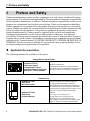
1
YASKAWA AC Drive 1000-Series Option Analog Monitor Installation Manual Type AO-A3 To properly use the product, read this manual thoroughly and retain for easy reference, inspection, and maintenance. Ensure the end user receives this manual. 安川インバータ 1000シリーズ オプション アナログモニタ 取扱説明書 形式 AO-A3 製品を安全にお使い頂くために,この取扱説明書を必ずお読みください。 また,本書をお手元に保管していただくとともに,最終的に本製品をご使用になる ユーザー様のお手元に確実に届けられるよう,お取り計らい願います。 MANUAL NO. TOBP C730600 40C Copyright © 2008 YASKAWA ELECTRIC CORPORATION All rights reserved. No part of this publication may be reproduced, stored in a retrieval system, or transmitted, in any form or by any means, mechanical, electronic, photocopying, recording, or otherwise, without the prior written permission of Yaskawa. No patent liability is assumed with respect to the use of the information contained herein. Moreover, because Yaskawa is constantly striving to improve its high-quality products, the information contained in this manual is subject to change without notice. Every precaution has been taken in the preparation of this manual. Yaskawa assumes no responsibility for errors or omissions. Neither is any liability assumed for damages resulting from the use of the information contained in this publication. 2 YASKAWA ELECTRIC TOBP C730600 40C 1000-Series Option AO-A3 Installation Manual Table of Contents 1 PREFACE AND SAFETY . . . . . . . . . . . . . . . . . . . . . . . . . . . . 4 2 PRODUCT OVERVIEW . . . . . . . . . . . . . . . . . . . . . . . . . . . . . . 7 3 RECEIVING . . . . . . . . . . . . . . . . . . . . . . . . . . . . . . . . . . . . . . . 8 4 OPTION COMPONENTS. . . . . . . . . . . . . . . . . . . . . . . . . . . . . 9 5 INSTALLATION PROCEDURE . . . . . . . . . . . . . . . . . . . . . . . 10 6 RELATED PARAMETERS . . . . . . . . . . . . . . . . . . . . . . . . . . 22 7 TROUBLESHOOTING. . . . . . . . . . . . . . . . . . . . . . . . . . . . . . 23 8 SPECIFICATIONS . . . . . . . . . . . . . . . . . . . . . . . . . . . . . . . . . 25 YASKAWA ELECTRIC TOBP C730600 40C 1000-Series Option AO-A3 Installation Manual 3 1 Preface and Safety 1 Preface and Safety Yaskawa manufactures products used as components in a wide variety of industrial systems and equipment. The selection and application of Yaskawa products remain the responsibility of the equipment manufacturer or end user. Yaskawa accepts no responsibility for the way its products are incorporated into the final system design. Under no circumstances should any Yaskawa product be incorporated into any product or design as the exclusive or sole safety control. Without exception, all controls should be designed to detect faults dynamically and fail safely under all circumstances. All systems or equipment designed to incorporate a product manufactured by Yaskawa must be supplied to the end user with appropriate warnings and instructions as to the safe use and operation of that part. Any warnings provided by Yaskawa must be promptly provided to the end user. Yaskawa offers an express warranty only as to the quality of its products in conforming to standards and specifications published in the Yaskawa manual. NO OTHER WARRANTY, EXPRESS OR IMPLIED, IS OFFERED. Yaskawa assumes no liability for any personal injury, property damage, losses, or claims arising from misapplication of its products. ◆ Applicable Documentation The following manuals are available for the option: Analog Monitor AO-A3 Option AO-A3 AO Yaskawa AC Drive 1000-Series Option Analog Monitor AO-A3 Installation Manual (This book) Manual No: TOBPC73060040 Read this manual first. The installation manual is packaged with the option and contains information required to install the option and set up related drive parameters. Yaskawa Drive Yaskawa AC Drive 1000-Series Quick Start Guide Yaskawa AC Drive 1000-Series Technical Manual 4 The drive manuals cover basic installation, wiring, operation procedures, functions, troubleshooting, and maintenance information. The manuals also include important information about parameter settings and drive tuning. Access these sites to obtain Yaskawa instruction manuals: U.S.: http://www.yaskawa.com Europe: http://www.yaskawa.eu.com Japan: http://www.e-mechatronics.com For questions, contact your local Yaskawa sales office or the nearest Yaskawa representative. YASKAWA ELECTRIC TOBP C730600 40C 1000-Series Option AO-A3 Installation Manual 1 Preface and Safety ◆ Terms Note: Indicates supplemental information that is not related to safety messages Drive: Yaskawa AC Drive 1000-Series Option: Yaskawa AC Drive 1000-Series Option Analog Monitor AO-A3 ◆ Registered Trademarks Trademarks are the property of their respective owners. ◆ Supplemental Safety Information Read and understand this manual before installing, operating, or servicing this option. Install the option according to this manual and local codes. The following conventions indicate safety messages in this manual. Failure to heed these messages could cause fatal injury or damage products and related equipment and systems. DANGER Indicates a hazardous situation, which, if not avoided, will result in death or serious injury. WARNING Indicates a hazardous situation, which, if not avoided, could result in death or serious injury. CAUTION Indicates a hazardous situation, which, if not avoided, could result in minor or moderate injury. NOTICE Indicates an equipment damage message. YASKAWA ELECTRIC TOBP C730600 40C 1000-Series Option AO-A3 Installation Manual 5 1 Preface and Safety ■ General Safety General Precautions • The diagrams in this book may include options and drives without covers or safety shields to illustrate details. Be sure to reinstall covers or shields before operating any devices. Use the option according to the instructions described in this manual. • Any illustrations, photographs, or examples used in this manual are provided as examples only and may not apply to all products to which this manual is applicable. • The products and specifications described in this manual or the content and presentation of the manual may be changed without notice to improve the product and/or the manual. • When ordering new copies of the manual, contact a Yaskawa representative or the nearest Yaskawa sales office and provide the manual number shown on the front cover. DANGER Heed the safety messages in this manual. Failure to comply will result in death or serious injury. The operating company is responsible for any injuries or equipment damage resulting from failure to heed the warnings in this manual. NOTICE Do not modify the drive or option circuitry. Failure to comply could result in damage to the drive or option and will void warranty. Yaskawa is not responsible for any modification of the product made by the user. This product must not be modified. Do not expose the drive or option to halogen group disinfectants. Failure to comply may cause damage to the electrical components in the drive or option. Do not pack the drive in wooden materials that have been fumigated or sterilized. Do not sterilize the entire package after the product is packed. 6 YASKAWA ELECTRIC TOBP C730600 40C 1000-Series Option AO-A3 Installation Manual 2 Product Overview 2 ◆ Product Overview About This Product The Analog Monitor Option AO-A3 allows the user to expand the number of available analog outputs to monitor drive performance. The option uses drive parameter settings and the output signal gain and bias to assign functions to output terminals V1 and V2. The option has two analog outputs, an 11-bit signed (1/2048) output resolution, and a -10 to 10 Vdc non-isolated output voltage. ◆ Applicable Models The option can be used with the drive models in Table 1. Table 1 Applicable Models Drive Series Drive Model Number A1000 All models L1000A All models YASKAWA ELECTRIC TOBP C730600 40C 1000-Series Option AO-A3 Installation Manual 7 3 Receiving 3 Receiving Please perform the following tasks upon receiving the option: • Inspect the option for damage. Contact the shipper immediately if the option appears damaged upon receipt. • Verify receipt of the correct model by checking the model number printed on the option nameplate. (Refer to Figure 1 on page 9 for more information) • Contact your supplier if you have received the wrong model or the option does not function properly. ◆ Option Package Contents Description: Option Ground Wires Screws (M3) Installation Manual MANUAL – AO-A3 AO Quantity: ◆ 1 3 3 1 Tools Required for Installation • A Phillips screwdriver (M3 metric / #1, #2 U.S. standard size) is required to install the option. • A straight-edge screwdriver (blade depth: 0.4 mm, width: 2.5 mm) is required to wire the option terminal block. • A pair of diagonal cutting pliers. • A small file or medium-grit sandpaper. Note: Tools required to prepare option cables for wiring are not listed in this manual. 8 YASKAWA ELECTRIC TOBP C730600 40C 1000-Series Option AO-A3 Installation Manual 4 Option Components 4 ◆ Option Components Analog Monitor AO-A3 Option Figure 1 B A D C Underside F AO-A3 AO E A – Terminal Block TB1 B – Potentiometers <1> C – Installation hole D – Connector (CN5) E – Model number F – Ground terminal and installation hole <1> <1> NOTICE: Do not adjust the potentiometers on the option. The potentiometers are factory set and may change the voltage output characteristics and cause output signal inaccuracy if misadjusted. <2> The ground wires provided in the option shipping package must be connected during installation. Figure 1 Analog Monitor AO-A3 Option Components ◆ Terminal Block TB1 V1 AC V2 AC FE AO Refer to Table 4 on page 21 for details on TB1 terminal functions and signal levels. YASKAWA ELECTRIC TOBP C730600 40C 1000-Series Option AO-A3 Installation Manual 9 5 Installation Procedure 5 ◆ Installation Procedure Section Safety DANGER Electric Shock Hazard Do not connect or disconnect wiring while the power is on. Failure to comply will result in death or serious injury. Disconnect all power to the drive and wait at least the amount of time specified on the drive front cover safety label. After all indicators are off, measure the DC bus voltage to confirm safe level, and check for unsafe voltages before servicing. The internal capacitor remains charged after the power supply is turned off. WARNING Electrical Shock Hazard Do not remove the front covers of the drive while the power is on. Failure to comply could result in death or serious injury. The diagrams in this section may include options and drives without covers or safety shields to show details. Be sure to reinstall covers or shields before operating any devices. Use the option according to the instructions described in this manual. Do not allow unqualified personnel to use equipment. Failure to comply could result in death or serious injury. Maintenance, inspection, and replacement of parts must be performed only by authorized personnel familiar with installation, adjustment, and maintenance of this product. Do not touch circuit boards while the power to the drive is on. Failure to comply could result in death or serious injury. Do not use damaged wires, stress the wiring, or damage the wire insulation. Failure to comply could result in death or serious injury. 10 YASKAWA ELECTRIC TOBP C730600 40C 1000-Series Option AO-A3 Installation Manual 5 Installation Procedure WARNING Fire Hazard Tighten all terminal screws to the specified tightening torque. Loose electrical connections could result in death or serious injury by fire due to overheating of electrical connections. NOTICE Damage to Equipment Observe proper electrostatic discharge (ESD) procedures when handling the option, drive, and circuit boards. Failure to comply may result in ESD damage to circuitry. Never shut the power off while the drive is running or outputting voltage. Failure to comply may cause the application to operate incorrectly or damage the drive. Do not operate damaged equipment. Failure to comply may cause further damage to the equipment. Do not connect or operate any equipment with visible damage or missing parts. Tighten all terminal screws to the specified tightening torque. Failure to comply could result in damage to the terminal block. Do not use unshielded cable for control wiring. Failure to comply may cause electrical interference resulting in poor system performance. Use shielded twisted-pair wires and ground the shield to the ground terminal of the drive. Properly connect all pins and connectors. Failure to comply may prevent proper operation and possibly damage equipment. Check wiring to ensure that all connections are correct after installing the option and connecting any other devices. Failure to comply may result in damage to the option. YASKAWA ELECTRIC TOBP C730600 40C 1000-Series Option AO-A3 Installation Manual 11 5 Installation Procedure ◆ Prior to Installing the Option Prior to installing the option, wire the drive, make the necessary connections to the drive terminals, and verify that the drive functions normally. Refer to the Quick Start Guide packaged with the drive for information on wiring and connecting the drive. Figure 2 shows an exploded view of the drive with the option and related components for reference. Figure 2 A L C B K D J I H A B C D E F – – – – – – E G F Insertion point for CN5 Option card Front cover Digital operator Terminal cover Removable tabs for wire routing G H I J K L – – – – – – Included screws Ground wire Drive grounding terminal (FE) Connector CN5-A Connector CN5-B Connector CN5-C Figure 2 Drive Components with Option 12 YASKAWA ELECTRIC TOBP C730600 40C 1000-Series Option AO-A3 Installation Manual 5 Installation Procedure ◆ Installing the Option Refer to the instructions below to install the option. 1. Shut off power to the drive, wait the appropriate amount of time for voltage to dissipate, then remove the digital operator (D), front cover (C), and terminal cover (E). Cover removal varies depending on drive size. Refer to the Quick Start Guide packaged with the drive for directions on removing the covers. DANGER! Electrical Shock Hazard. Disconnect all power to the drive and wait at least the amount of time specified on the drive front cover safety label. After all indicators are off, measure the DC bus voltage to confirm safe level, and check for unsafe voltages before servicing to prevent electric shock. The internal capacitor remains charged even after the power supply is turned off. NOTICE: Damage to Equipment. Observe proper electrostatic discharge procedures (ESD) when handling the option, drive, and circuit boards. Failure to comply may result in ESD damage to circuitry. Figure 3 C D E Figure 3 Remove the Front Cover, Terminal Cover, and Digital Operator YASKAWA ELECTRIC TOBP C730600 40C 1000-Series Option AO-A3 Installation Manual 13 5 Installation Procedure 2. Insert the option card (B) into the CN5-A (J), CN5-B (K), or CN5-C (L) connector located on the drive and fasten it into place using one of the included screws (G). Figure 4 L B K J G Figure 4 Insert the Option Card 14 YASKAWA ELECTRIC TOBP C730600 40C 1000-Series Option AO-A3 Installation Manual 5 Installation Procedure 3. Connect one end of the ground wire (H) to the ground terminal (I) using one of the remaining screws (G). Connect the other end of the ground wire (H) to the remaining ground terminal and installation hole on the option (B) using the last remaining provided screw (G). Figure 5 B I H G Figure 5 Connect the Ground Wire Note: 1. The option package includes three ground wires. Use the longest wire when plugging the option into connector CN5-C on the drive side. Use the next longest wire when plugging the option into connector CN5-B. Use the shortest wire when plugging the option into connector CN5-A. Refer to Option Package Contents on page 8 for more information. 2. There are two screw holes on the drive for use as ground terminals (J). When connecting three options, two ground wires will need to share the same drive ground terminal. YASKAWA ELECTRIC TOBP C730600 40C 1000-Series Option AO-A3 Installation Manual 15 5 Installation Procedure 4. Prepare and connect the wire ends as shown in Figure 6 and Figure 7. Refer to Wire Gauges and Tightening Torques on page 20 to confirm that the proper tightening torque is applied to each terminal. Take particular precaution to ensure that each wire is properly connected and wire insulation is not accidentally pinched into electrical terminals. WARNING! Fire Hazard. Tighten all terminal screws according to the specified tightening torque. Loose electrical connections could result in death or serious injury by fire due to overheating electrical connections. Tightening screws beyond the specified tightening torque may cause erroneous operation, damage the terminal block, or cause a fire. NOTICE: Heat shrink tubing or electrical tape may be required to ensure that cable shielding does not contact other wiring. Insufficient insulation may cause a short circuit and damage the option or drive. Figure 6 Insulation To customer circuit Option terminal FE AO Shield sheath (Insulate with electrical tape or shrink tubing) Figure 6 Preparing Ends of Shielded Cable Figure 7 Preparing wire ends: Screwdriver blade size AO Pull back the shielding and lightly twist the end with fingers, keeping the ends from fraying. about 5.5 mm (7/32”) When not using crimped insulated sleeves Blade depth of 0.4 mm or less Blade width of 2.5 mm or less Loosen the screws and insert the wire into the opening on the terminal block. Option terminal block To customer circuit (do not solder ends) Figure 7 Preparing and Connecting Cable Wiring 16 YASKAWA ELECTRIC TOBP C730600 40C 1000-Series Option AO-A3 Installation Manual 5 Installation Procedure 5. Wire the customer-supplied circuit to the terminal block on the option. Refer to Figure 8 for wiring instructions. Connection Diagram Refer to Table 4 on page 21 for a detailed description of the option board terminal functions. To ensure accurate control, use stable power supply for the voltage reference source. Figure 8 AO-A3 Drive R/L1 T/L2 S/L3 CN5 TB1 V1 Monitor AC 㧙 V2 AC 㧙 AM FM 㧗 㧗 FE FE Ground wire Twisted-pair shielded line Main circuit terminal Control circuit terminal AO Figure 8 Option Connection Diagram NOTICE: Do not adjust the potentiometers on the option. The potentiometers are factory set and may change the voltage output characteristics and cause output signal inaccuracy if misadjusted. YASKAWA ELECTRIC TOBP C730600 40C 1000-Series Option AO-A3 Installation Manual 17 5 Installation Procedure 6. Route the option wiring. Depending on the drive model, some drives may require routing the wiring through the side of the front cover to the outside. In these cases, cut out the perforated openings on the left side of the drive front cover as shown in Figure 9-A and leave no sharp edges to damage wiring. Route the wiring inside the enclosure as shown in Figure 9-B for drives that do not require routing through the front cover. Refer to the Peripheral Devices & Options section of the drive Technical Manual for more information. Figure 9 A A – Route wires through the openings provided on the left side of the front cover. <1> B B – Use the open space provided inside the drive to route option wiring. <1> The drive will not meet NEMA Type 1 requirements if wiring is exposed outside the enclosure. Figure 9 Wire Routing Examples 18 YASKAWA ELECTRIC TOBP C730600 40C 1000-Series Option AO-A3 Installation Manual 5 Installation Procedure 7. Replace and secure the front covers of the drive (C, E) and replace the digital operator (D). Figure 10 C D E Figure 10 Replace the Front Covers and Digital Operator Note: Take proper precautions when wiring the option so that the front covers will easily fit back onto the drive. Make sure cables are not pinched between the front covers and the drive when replacing the covers. 8. Set drive parameters in Table 5 for proper option performance. YASKAWA ELECTRIC TOBP C730600 40C 1000-Series Option AO-A3 Installation Manual 19 5 Installation Procedure ◆ Wire Gauges, Tightening Torques, and Crimp Terminals ■ Wire Gauges and Tightening Torques Wire gauge and torque specifications are listed in Table 2. Table 2 Wire Gauges and Tightening Torques Bare Cable Terminal Screw Tightening Torque Applicable Recomm. signal Size Nxm (inxlb) Gauges mm2 Gauge mm2 V1, V2, AC, FE ■ M2 Stranded wire: 0.25 to 1.0 0.22 to 0.25 (24 to 17 AWG) (1.95 to 2.21) Solid wire: 0.25 to 1.5 (24 to 16 AWG) 0.75 (18 AWG) Crimp Terminals Applicable Gauges mm2 Recomm. Gauge mm2 0.25 to 0.5 (24 to 20 AWG) 0.5 (20 AWG) Wire Type Shielded twisted pair, etc. Crimp Terminals Yaskawa recommends using CRIMPFOX 6 by Phoenix Contact or equivalent crimp terminals with the specifications listed in Table 3 for wiring to ensure proper connections. Note: Properly trim wire ends so loose wire ends do not extend from the crimp terminals. Table 3 Crimp Terminal Sizes d1 20 6 mm L d2 Wire Gauge mm2 Phoenix Contact Model L mm (in) d1 mm (in) d2 mm (in) 0.25 (24 AWG) AI 0.25 - 6YE 10.5 (13/32) 0.8 (1/32) 2 (5/64) 0.34 (22 AWG) AI 0.34 - 6TQ 10.5 (13/32) 0.8 (1/32) 2 (5/64) 0.5 (20 AWG) AI 0.5 - 6WH 14 (9/16) 1.1 (3/64) 2.5 (3/32) YASKAWA ELECTRIC TOBP C730600 40C 1000-Series Option AO-A3 Installation Manual 5 Installation Procedure ◆ Terminal Functions Table 4 Option Terminal Functions Terminal Function V1 Analog voltage output 1 V2 Analog voltage output 2 AC Common FE Ground Signal Level -10 to 10 V Description • Analog voltage output for an external monitoring device <1> Output resolution 11-bit plus sign (1/2048) • Max. load current 3 mA 0V Common for analog voltage output – Used for grounding shielded lines <1> Set the functions and output levels for terminals V1 and V2 using drive parameters. See the drive Quick Start Guide or Technical Manual for directions on setting parameters. YASKAWA ELECTRIC TOBP C730600 40C 1000-Series Option AO-A3 Installation Manual 21 6 Related Parameters 6 Related Parameters The parameters outlined in the following sections are used to set up the drive for operation with the option. Set parameters as needed. Parameter setting methods can be found in the drive Quick Start Guide or Technical Manual. ◆ Parameter Table Table 5 Related Parameters No. (Addr. Hex) Name Description Values Terminal V1 Monitor Selection Sets the monitor signal for output from terminal V1. Set this parameter to the last three digits of the desired U- monitor. Some U parameters are available only in certain control modes. For example, enter “103” for U1-03. Default: 102 (output frequency) Range: 000 to 999 Terminal V1 Monitor Gain Sets the gain for voltage output via terminal V1, where 100% equals 10 V output. Terminal output voltage is limited to 10 V. Default: 100.0% Min: -999.9 Max: 999.9 F4-03 (393) Terminal V2 Monitor Selection Sets the monitor signal for output from terminal V2. Set this parameter to the last three digits of the Default: 0.0% desired U- monitor. Some U parameters are Min: -999.9 available only in certain control modes. Max: 999.9 For example, enter “103” for U1-03. F4-04 (394) Terminal V2 Monitor Gain Sets the gain for voltage output via terminal V2, where 100% equals 10 V output. Terminal output voltage is limited to 10 V. <1> Default: 50.0% Min: -999.9 Max: 999.9 F4-05 (395) Terminal V1 Monitor Bias Sets the amount of bias added to the voltage output via terminal V1. <1> Default: 0.0% Min: -999.9 Max: 999.9 F4-06 (396) Terminal V2 Monitor Bias Sets the amount of bias added to the voltage output via terminal V2. <1> Default: 0.0% Min: -999.9 Max: 999.9 F4-07 (397) Terminal V1 Signal Level F4-08 (398) Terminal V2 Signal Level F4-01 (391) F4-02 (392) Sets the voltage level for the analog output. 0: 0 to +10 Vdc 1: -10 to +10 Vdc Default: 0 Range: 0, 1 Default: 0 Range: 0, 1 <1> The drive outputs voltage while this parameter is being adjusted. Voltage levels can be adjusted to match the specifications of an external meter. 22 YASKAWA ELECTRIC TOBP C730600 40C 1000-Series Option AO-A3 Installation Manual 7 Troubleshooting 7 ◆ Troubleshooting Drive-Side Error Codes Table 6 lists the various fault codes related to the option. Refer to the drive Technical Manual for further details on fault codes. Check the following items first when an error code occurs on the drive: • Are the cables connected properly and securely? • Is the option is properly installed to the drive? • Did a momentary power loss occur? Table 6 Fault Displays, Causes, and Possible Solutions Digital Operator Display oFA01 Fault Name Option Fault (CN5-A) Option is not properly connected Cause Possible Solution Option at drive port CN5-A was changed during run. Turn the power off and check the connectors between the drive and option. Digital Operator Display oFb01 Fault Name Option Fault (CN5-B) Option is not properly connected Cause Possible Solution Option at drive port CN5-B was changed during run. Turn the power off and check the connectors between the drive and option. Digital Operator Display oFb02 Cause Fault Name Option Fault (CN5-B) Two of the same options are connected simultaneously. Possible Solution Same type of option connected to ports CN5-A and CN5-B. Digital Operator Display oFC01 Use only compatible options. Fault Name Option connection error at drive port CN5-C Cause Possible Solution Option at drive port CN5-C was changed during run. Turn the power off and check the connectors between the drive and option. YASKAWA ELECTRIC TOBP C730600 40C 1000-Series Option AO-A3 Installation Manual 23 7 Troubleshooting Digital Operator Display oFC02 Fault Name Option Fault (CN5-C) Two of the same options are connected simultaneously. Cause Possible Solution Same type of option connected to drive ports CN5-A, CN5-B, and CN5-C. ◆ Use only compatible options. Preventing Noise Interference Take the following steps to prevent erroneous operation caused by noise interference: • Use shielded wire for the signal lines. • Limit the length of wiring under 50 m (164 ft.). • Separate the control wiring to the option, main circuit wiring, and power lines. ■ Interface Circuit Figure 11 Signal processor – + V1, V2 AC AO Figure 11 Output Interface Circuit 24 YASKAWA ELECTRIC TOBP C730600 40C 1000-Series Option AO-A3 Installation Manual 8 Specifications 8 Specifications Table 7 Option Specifications Item Description Model AO-A3 Analog Output Terminals 2 terminals Voltage Output • Output signal voltage: -10 to 10 Vdc • Output resolution: 11 bit plus sign (1/2048) • Max. load current: 3 mA Ambient Temperature -10 °C to +50 °C (14 °F to 122 °F) Humidity 95% RH or lower with no condensation Storage Temperature -20 °C to +60 °C (-4 °F to 140 °F) allowed for short-term transport of the product Area of use Indoor (free of corrosive gas, airborne particles, etc.) Altitude 1000 m (3280 ft.) or lower YASKAWA ELECTRIC TOBP C730600 40C 1000-Series Option AO-A3 Installation Manual 25 8 Specifications ◆ Revision History Revision dates and manual numbers are located on the bottom of the back cover. MANUAL NO. TOBP C730600 40B Published in Japan May 2010 08-7 1 AO Revision number Date of original publication Date of publication Date of Publication 26 Revision Number February 2011 4 July 2010 3 July 2010 2 May 2010 July 2008 Section Front cover, back cover Revised Content Revision: Format Chapter 3, 4, 5, and 7 Edited for clarity. Back cover Revision: Address Entire Document Edited for procedural clarity and readability. Back cover Revision: Address 1 Back cover Revision: Address − − First edition YASKAWA ELECTRIC TOBP C730600 40C 1000-Series Option AO-A3 Installation Manual YASKAWA AC Drive 1000-Series Option Analog Monitor Installation Manual DRIVE CENTER (INVERTER PLANT) 2-13-1, Nishimiyaichi, Yukuhashi, Fukuoka, 824-8511, Japan Phone: 81-930-25-3844 Fax: 81-930-25-4369 http://www.yaskawa.co.jp YASKAWA ELECTRIC CORPORATION New Pier Takeshiba South Tower, 1-16-1, Kaigan, Minatoku, Tokyo, 105-6891, Japan Phone: 81-3-5402-4502 Fax: 81-3-5402-4580 http://www.yaskawa.co.jp YASKAWA AMERICA, INC. 2121 Norman Drive South, Waukegan, IL 60085, U.S.A. Phone: (800) YASKAWA (927-5292) or 1-847-887-7000 Fax: 1-847-887-7310 http://www.yaskawa.com YASKAWA ELÉTRICO DO BRASIL LTDA. Avenda Fagundes Filho, 620 Bairro Saude, São Paulo, SP04304-000, Brasil Phone: 55-11-3585-1100 Fax: 55-11-5581-8795 http://www.yaskawa.com.br YASKAWA EUROPE GmbH Hauptstrasse 185, 65760 Eschborn, Germany Phone: 49-6196-569-300 Fax: 49-6196-569-398 http://www.yaskawa.eu.com YASKAWA ELECTRIC UK LTD. 1 Hunt Hill Orchardton Woods, Cumbernauld, G68 9LF, United Kingdom Phone: 44-1236-735000 Fax: 44-1236-458182 http://www.yaskawa.co.uk YASKAWA ELECTRIC KOREA CORPORATION 7F, Doore Bldg. 24, Yeoido-dong, Yeoungdungpo-gu, Seoul, 150-877, Korea Phone: 82-2-784-7844 Fax: 82-2-784-8495 http://www.yaskawa.co.kr YASKAWA ELECTRIC (SINGAPORE) PTE. LTD. 151 Lorong Chuan, #04-01, New Tech Park, 556741, Singapore Phone: 65-6282-3003 Fax: 65-6289-3003 http://www.yaskawa.com.sg YASKAWA ELECTRIC (SHANGHAI) CO., LTD. No. 18 Xizang Zhong Road, 17F, Harbour Ring Plaza, Shanghai, 200001, China Phone: 86-21-5385-2200 Fax: 86-21-5385-3299 http://www.yaskawa.com.cn YASKAWA ELECTRIC (SHANGHAI) CO., LTD. BEIJING OFFICE Room 1011, Tower W3 Oriental Plaza, No. 1 East Chang An Ave., Dong Cheng District, Beijing, 100738, China Phone: 86-10-8518-4086 Fax: 86-10-8518-4082 YASKAWA ELECTRIC TAIWAN CORPORATION 9F, 16, Nanking E. Rd., Sec. 3, Taipei, 104, Taiwan Phone: 886-2-2502-5003 Fax: 886-2-2505-1280 YASKAWA ELECTRIC CORPORATION In the event that the end user of this product is to be the military and said product is to be employed in any weapons systems or the manufacture thereof, the export will fall under the relevant regulations as stipulated in the Foreign Exchange and Foreign Trade Regulations. Therefore, be sure to follow all procedures and submit all relevant documentation according to any and all rules, regulations and laws that may apply. Specifications are subject to change without notice for ongoing product modifications and improvements. © 2008-2011 YASKAWA ELECTRIC CORPORATION. All rights reserved. MANUAL NO. TOBP C730600 40C Published in Japan February 2011 08-7 4 -0 10-10-6