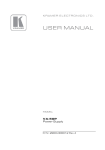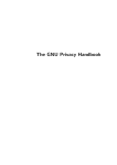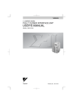
1
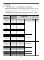
Σ-V シリーズ ACサーボパック SGDV 安全上のご注意 形式 SGDV-FA SGDV-AA SGDV-DA 製品を安全にお使い頂くために,本書を必ずお読みください。 また,本書をお手元に保管していただくとともに,最終的に 本製品をご使用になるユーザー様のお手元に確実に届けられるよう, お取り計らい願います。 Σ-V SERIES AC SERVOPACK SGDV SAFETY PRECAUTIONS Type SGDV-FA SGDV-AA SGDV-DA To properly use the product, read this manual thoroughly and retain for easy reference, inspection, and maintenance. Ensure the end user receives this manual. MANUAL NO. TOBP C710800 10E Copyright © 2007 YASKAWA ELECTRIC CORPORATION All rights reserved. No part of this publication may be reproduced, stored in a retrieval system, or transmitted, in any form, or by any means, mechanical, electronic, photocopying, recording, or otherwise, without the prior written permission of Yaskawa. No patent liability is assumed with respect to the use of the information contained herein. Moreover, because Yaskawa is constantly striving to improve its high-quality products, the information contained in this manual is subject to change without notice. Every precaution has been taken in the preparation of this manual. Nevertheless, Yaskawa assumes no responsibility for errors or omissions. Neither is any liability assumed for damages resulting from the use of the information contained in this publication. General Precautions • The drawings presented in this manual are sometimes shown without covers or protective guards. Always replace the cover or protective guard as specified first, and then operate the products in accordance with the manual. • The drawings presented in this manual are typical examples and may not match the product you received. • This manual is subject to change due to product improvement, specification modification, and manual improvement. When this manual is revised, the manual code is updated and the new manual is published as a next edition. The edition number appears on the front and back covers. • Yaskawa will not take responsibility for the results of unauthorized modifications of this product. Yaskawa shall not be liable for any damages or troubles resulting from unauthorized modification. Safety Information The following conventions are used to indicate precautions in this manual. Failure to heed precautions provided in this manual can result in serious or possibly even fatal injury or damage to the products or to related equipment and systems. WARNING CAUTION PROHIBITED Indicates precautions that, if not heeded, could possibly result in loss of life or serious injury. Indicates precautions that, if not heeded, could result in relatively serious or minor injury, damage to the product, or faulty operation. In some situations, the precautions indicated could have series consequences if not heeded. Indicates prohibited actions that must not be performed. For example, this symbol would be used to indicate that fire is prohibited as follows: MANDATORY . Indicates compulsory actions that must be performed. For example, this symbol would be used as follows to indicate that grounding is compulsory: E-1 . Notes for Safe Operation WARNING • Never touch any rotating motor parts while the motor is running. Failure to observe this warning may result in injury. • Before starting operation with a machine connected, make sure that an emergency stop can be applied at any time. Failure to observe this warning may result in injury or damage to the product. • Never touch the inside of the SERVOPACKs. Failure to observe this warning may result in electric shock. • Do not remove the cover of power supply terminal while the power is ON. Failure to observe this warning may result in electric shock. • Do not touch terminals for five minutes after the power is turned OFF. Residual voltage may cause electric shock. • Do not touch terminals while the charge indicator is lit. Residual voltage may cause electric shock. • Do not touch terminals for five minutes after voltage resistance test. Residual voltage may cause electric shock. • Follow the procedures and instructions for the trial operation as noted in the applicable manual for that product. Malfunctions that occur after the servomotor is connected to the equipment not only damage the equipment, but may also cause an accident resulting in death or injury. • The output range of multi-turn data for Σ-V series absolute detection system differs from that for conventional systems (15-bit encoder and 12-bit encoder). Especially when “Infinite length positioning system” of Σ series is to be configured with Σ-V series, be sure to make the system modification. E-2 WARNING • The multi-turn limit value must be changed only for special applications. Changing it inappropriately or unintentionally can be dangerous. • If the Multi-turn Limit Disagreement alarm occurs, check the setting of parameter Pn205 in the SERVOPACK to be sure that it is correct. If Fn013 is executed when an incorrect value is set in Pn205, an incorrect value will be set in the encoder. The alarm will disappear even if an incorrect value is set, but incorrect positions will be detected, resulting in a dangerous situation where the machine will move to unexpected positions. • Do not remove the front cover, cables, connectors, or optional items on the foreside while the power is ON. Failure to observe this warning may result in electric shock. • Do not damage, press, exert excessive force or place heavy objects on the cables. Failure to observe this warning may result in electric shock, stopping operation of the product, or fire. • Do not modify the product. Failure to observe this warning may result in injury, damage to the product, or fire. • Provide an appropriate stopping device on the machine side to ensure safety. A holding brake for a servomotor with brake is not a stopping device for ensuring safety. Failure to observe this warning may result in injury. • Do not come close to the machine immediately after resetting momentary power loss to avoid an unexpected restart. Take appropriate measures to ensure safety against an unexpected restart. Failure to observe this warning may result in injury. • Connect the ground terminal to electrical codes (ground resistance: 100 Ω or less for a SERVOPACK with a 200 V/ 100 V power supply. 10 Ω or less for a SERVOPACK with a 400 V power supply). Improper grounding may result in electric shock or fire. E-3 WARNING • Installation, disassembly, or repair must be performed only by authorized personnel. Failure to observe this warning may result in electric shock or injury. • The person who designs a system using the safety function (Hard Wire Baseblock function) must have full knowledge of the related safety standards and full understanding of the instructions in Σ-V series User’s Manual Design and Maintenance. Failure to observe this warning may result in injury or damage to the product. E-4 Storage and Transportation CAUTION • Do not store or install the product in the following places. • Locations subject to direct sunlight. • Locations subject to temperatures outside the range specified in the storage/installation temperature conditions. • Locations subject to humidity outside the range specified in the storage/installation humidity conditions. • Locations subject to condensation as the result of extreme changes in temperature. • Locations subject to corrosive or flammable gases. • Locations subject to dust, salts, or iron dust. • Locations subject to exposure to water, oil, or chemicals. • Locations subject to shock or vibration. Failure to observe this caution may result in fire, electric shock, or damage to the product. • Do not hold the product by the cables, motor shaft, or detector while transporting it. Failure to observe this caution may result in injury or malfunction. • Do not place any load exceeding the limit specified on the packing box. Failure to observe this caution may result in injury or malfunction. • If disinfectants or insecticides must be used to treat packing materials such as wooden frames, pallets, or plywood, the packing materials must be treated before the product is packaged, and methods other than fumigation must be used. Example: Heat treatment, where materials are kiln-dried to a core temperature of 56°C for 30 minutes or more. If the electronic products, which include stand-alone products and products installed in machines, are packed with fumigated wooden materials, the electrical components may be greatly damaged by the gases or fumes resulting from the fumigation process. In particular, disinfectants containing halogen, which includes chlorine, fluorine, bromine, or iodine can contribute to the erosion of the capacitors. E-5 Installation CAUTION • Never use the products in an environment subject to water, corrosive gases, inflammable gases, or combustibles. Failure to observe this caution may result in electric shock or fire. • Do not step on or place a heavy object on the product. Failure to observe this caution may result in injury or malfunction. • Do not cover the inlet or outlet ports and prevent any foreign objects from entering the product. Failure to observe this caution may cause internal elements to deteriorate resulting in malfunction or fire. • Be sure to install the product in the correct direction. Failure to observe this caution may result in malfunction. • Provide the specified clearances between the SERVOPACK and the control panel or with other devices. Failure to observe this caution may result in fire or malfunction. • Do not apply any strong impact. Failure to observe this caution may result in malfunction. E-6 Wiring CAUTION • Be sure to wire correctly and securely. Failure to observe this caution may result in motor overrun, injury, or malfunction. • Do not connect a commercial power supply to the U, V, or W servomotor connection terminals. Failure to observe this caution may result in injury or fire. • Securely connect the power supply terminal screws and servomotor connection terminal screws. Failure to observe this caution may result in fire. • Do not bundle or run the main circuit cables and input/output signal lines or the encoder cables together in the same duct. Keep power and signal lines separated by at least 30 cm. • Use twisted-pair shielded wires or multi-core twisted pair shielded wires for input/output signal lines and the encoder cables. The maximum length is 3 m for input/output signal lines and 20 m for encoder cables. • Do not touch the power terminals for 5 minutes after turning power OFF because high voltage may still remain in the SERVOPACK. Make sure the charge indicator is out first before wiring or starting an inspection. • Observe the following precautions when wiring main circuit terminal blocks. • If the main circuit terminal is the connector, remove the connector from the SERVOPACK prior to wiring. • Insert only one wire per insertion slot on the terminal block and the connector. • Make sure that the core wire is not electrically shorted to adjacent core wires. E-7 CAUTION • Install the battery at either the host controller and the battery unit of the encoder. It is dangerous to install batteries at both simultaneously, because that sets up a loop circuit between the batteries. • Always use the specified power supply voltage. An incorrect voltage may result in fire. • Take appropriate measures to ensure that the input power supply is supplied within the specified voltage fluctuation range. Be particularly careful in places where the power supply is unstable. An incorrect power supply may result in damage to the product. • Install external breakers or other safety devices against short-circuiting in external wiring. Failure to observe this caution may result in fire. • Take appropriate and sufficient countermeasures for each when installing systems in the following locations. • Locations subject to static electricity or other forms of noise. • Locations subject to strong electromagnetic fields and magnetic fields. • Locations subject to possible exposure to radioactivity. • Locations close to power supplies. Failure to observe this caution may result in damage to the product. • Do not reverse the polarity of the battery when connecting it. Failure to observe this caution may damage the battery, SERVOPACK, and servomotor or cause it to explode. • Wiring or inspection must be performed by a technical expert. E-8 Operation CAUTION • Conduct trial operation on the servomotor alone with the motor shaft disconnected from machine to avoid any unexpected accidents. Failure to observe this caution may result in injury. • Before starting operation with a machine connected, change the settings to match the parameters of the machine. Starting operation without matching the proper settings may cause the machine to run out of control or malfunction. • Avoid frequently turning power ON and OFF. Since the SERVOPACK has a capacitor in the power supply, a high charging current flows when power is turned ON. Frequently turning power ON and OFF causes main power devices like capacitors and fuses to deteriorate, resulting in unexpected problems. • Forced stop function with forward/reverse overtravel is not effective during JOG mode operation using utility function Fn002 and zero point search using Fn003. • When using the servomotor for a vertical axis, install the safety devices to prevent workpieces to fall off due to occurrence of alarm or overtravel. Set the servomotor so that it will stop in the zero clamp state at occurrence of overtravel. Failure to observe this caution may cause workpieces to fall off due to overtravel. • When not using the tuning-less function, set to the correct moment of inertia ratio Pn103. Setting to an incorrect moment of inertia ratio may cause vibration. • Do not touch the SERVOPACK heatsinks, regenerative resistor, or servomotor while power is ON or soon after the power is turned OFF. Failure to observe this caution may result in burns due to high temperatures. • Do not make any extreme adjustments or setting changes of parameters. Failure to observe this caution may result in injury or damage to the product due to unstable operation. E-9 CAUTION • When an alarm occurs, remove the cause, reset the alarm after confirming safety, and then resume operation. Failure to observe this caution may result in damage to the product, fire, or injury. • Do not use the holding brake of the servomotor for braking. Failure to observe this caution may result in malfunction. • Always use the servomotor and SERVOPACK in one of the specified combinations. Failure to observe this caution so may result in fire or malfunction. • The servomotor stopping method of turning the main-circuit or control-circuit power OFF without turning the servo OFF during operation can not be set in Parameter Pn001. • When turning the main-circuit power OFF without turning the servo OFF: The servomotor will be stopped by dynamic braking (DB). • When turning the control-circuit power OFF without turning the servo OFF: The stopping method will vary depending on the SERVOPACK model. Refer to the Σ-V Series User's Manual Design and Maintenance for details. Maintenance and Inspection CAUTION • Do not disassemble the SERVOPACK. Failure to observe this caution may result in electric shock or injury. • Do not attempt to change wiring while the power is ON. Failure to observe this caution may result in electric shock or injury. • When replacing the SERVOPACK, resume operation only after transferring the previous SERVOPACK parameters to the new SERVOPACK. Failure to observe this caution may result in damage to the product. E-10 Disposal CAUTION • When disposing of the products, treat them as ordinary industrial waste. Warranty Information Free Warranty Period This product is warranted for twelve months after being delivered to Yaskawa’s customer or if applicable eighteen months from the date of shipment from Yaskawa’s factory whichever comes first. Scope of Warranty If a Yaskawa product is found to be defective due to Yaskawa workmanship or materials and the defect occurs during the warranty period, Yaskawa will provide a replacement, repair the defective product, and provide shipping to and from the site free of charge. However, if the Yaskawa Authorized Service Center determines that the problem with a Yaskawa product is not due to defects in Yaskawa’s workmanship or materials, then the customer will be responsible for the cost of any necessary repairs. E-11 1 Checking Products on Delivery Check the following items when the Σ-V Series SERVOPACK is delivered. Items Check Method Is the delivered SERVOPACK the one Check the model numbers marked on the that was ordered? nameplates of the SERVOPACK. Check the accessories as well. Is there any damage? Check the overall appearance, and check for damage or scratches that may have occurred during shipping. Are there any loose screws? Check screws for looseness using a screwdriver. If any of the above items are faulty or incorrect, contact your Yaskawa sales representative or the dealer from whom you purchased the products. 1.1 Nameplate Use proper grounding techniques. MODEL SGDV-1R6A01A Applicable power supply SERVOPACK type Rated output current Serial number SERVOPACK nameplate E-12 2 Installation 2 Installation Observe the Installation instructions in Σ-V series User’s Manual Setup Rotational Motor (SIEPS80000043) or Σ-V series User’s Manual Setup Linear Motor (SIEPS80000044). For installation sites, use proper care with the following notes. Situation When installed in a control panel Notes on Installation • Design the control panel size, unit layout, and cooling method so that the surrounding air temperature of the SERVOPACK does not exceed 55°C. • When installing multiple SERVOPACKs side by side in a control panel, install cooling fans and provide sufficient space around each SERVOPACK to allow cooling by fan and natural convection. Provide a space of 5 mm or more between each of the SGDV-R70A, R90A, 1R6A, or 2R8A SERVOPACKs and 10 mm or more for any other SERVOPACKs. When installed near a heat- Suppress radiation heat from the heating unit and a ing unit temperature rise caused by convection so that the surrounding air temperature of the SERVOPACK does not exceed 55°C. When installed near a Install a vibration isolator underneath the SERVOsource of vibration PACK to prevent it from receiving vibration. When installed in a place re- Corrosive gases do not immediately affect the SERceiving corrosive gases VOPACK but will eventually cause SERVOPACK or contactor-related devices to malfunction. Take appropriate action to protect against corrosive gases. Others • Avoid installation in a hot and humid place or where excessive dust or iron powder is present in the air. • Be sure there is no condensation or freezing. • Keep the surrounding air temperature 45 °C or less to ensure long-term reliability. E-13 3 Wiring 3.1 Molded-case Circuit Breaker and Fuse When choosing a molded-case circuit breaker and a fuse capacity, refer to this table. The rated input current of the SERVOPACK is the nominal value at the rated load. Select the appropriate capacity in accordance with the specified derating. Cutoff characteristics (25°C): 300% five seconds min. Power Supply SERVOPACK Capacity per Model SGDV- SERVOPACK (kVA) R70F R90F 2R1F 2R8F R70A R90A 1R6A 2R8A 3R8A 5R5A 7R6A 120A 180A 200A 330A 470A 550A 590A 780A 1R9D 3R5D 5R4D 8R4D 120D 170D 210D 260D 280D 370D 0.2 0.3 0.7 1.4 0.2 0.3 0.6 1 1.4 1.6 2.3 3.2 4 5.9 7.5 10.7 14.6 21.7 29.6 1.1 2.3 3.5 4.5 7.1 11.7 12.4 14.4 21.9 30.6 Rated Input Current of SERVOPACK (Arms) Main circuit power supply 1.5 2.5 5 10 1.0 1.0 2.0 3.0 3.0 6.0 6.0 7.5 10 15 25 29 37 54 73 1.4 2.9 4.3 5.8 8.6 14.5 17.4 21.7 31.8 43.4 E-14 Control circuit power supply 0.38 Rated Voltage Fuse MCCB 250 V 240 V 600 V 480 V 0.2 0.25 0.3 0.45 1.2 1.4 1.5 1.7 3 Wiring 3.2 Main Circuit Wiring Do not use SGDV SERVOPACKs in a power-supply environment where a short-circuit current of 5000 A or more flows after a short circuit occurs. The maximum available voltage is • With 100V class: 115 Vrms • With 200V class: 230 Vrms • With 400V class: 480 Vrms (neutral grounding) SERVOPACKs must be used with UL-listed fuses or circuit breakers, in accordance with the guidelines of the National Electrical Code (NEC). Use 75 °C heat-resistant copper wires or an equivalent. Use a flexible cable for moving parts when the SERVOPACK is used with a linear servomotor. 3.3 Wire Size and Tightening Torque Cable Types • Wire sizes are selected for three cables per bundle at 40°C surrounding air temperature with the rated current. • Use cable with a minimum withstand voltage of 600 V for main circuits. • If cables are bundled in PVC or metal ducts, consider the reduction ratio of the allowable current. • Use heat-resistant cables under high surrounding air or panel temperatures where normal vinyl cables will rapidly deteriorate. • Use cables within the allowable moment of inertia. • Do not use cables under continuous regenerative state. The following table shows the wire size and allowable current for three cables. Use a cable whose specifications meet or are less than the values in the table. E-15 600-V Heat-resistant Vinyl Cables (HIV) AWG Size 20 18 16 14 12 10 8 6 4 Nominal Cross Section Diameter mm2 0.5 0.75 0.9 1.25 2.0 3.5 5.5 8.0 14.0 22.0 Configuration Number of wires/mm2 Conductive Resistance Ω/km 19/0.18 30/0.18 37/0.18 50/0.18 7/0.6 7/0.8 7/1.0 7/1.2 7/1.6 7/2.0 39.5 26.0 24.4 15.6 9.53 5.41 3.47 2.41 1.35 0.85 Allowable Current at Surrounding Air Temperature A 30°C 40°C 50°C 6.6 8.8 9.0 12.0 23 33 43 55 79 91 5.6 7.0 7.7 11.0 20 29 38 49 70 81 4.5 5.5 6.0 8.5 16 24 31 40 57 66 Note: The values in the table are only for reference. Wire Size The following table shows the markings for the power-supply terminals, the wire sizes, the screw sizes and torque for the ground terminals of the SERVOPACK. L1, L2, L3: Main circuit power-supply input terminals U, V, W: Servomotor connection terminals L1C, L2C / 24 V, 0 V: Control power input terminals B1, B2: External regenerative resistor terminals : Ground terminal E-16 3 Wiring Wire Size and Tightening Torque for Connectors Terminal Symbol and Wire Size(mm2) SERVOPACK Model SGDVR70F R90F 2R1F 2R8F R70A R90A 1R6A 2R8A 3R8A 5R5A 7R6A 120A 1R9D 3R5D 5R4D L1, L2, L3 U, V, W L1C, L2C B1/+, B2 /L1, L2 /24V, 0V HIV 1.25 Ground Terminal Terminal Tightening Screw Torque Size (Nxm) M4 1.2 to 1.4 HIV 1.25 HIV 1.25 HIV 1.25 HIV2.0 or more HIV 1.25 HIV 1.25 HIV 1.25 HIV2.0 or more M4 1.2 to 1.4 HIV 1.25 HIV 1.25 HIV2.0 or more M4 1.2 to 1.4 HIV 2.0 HIV 1.25 HIV 2.0 HIV 1.25 HIV 2.0 HIV 1.25 E-17 Wire Size and Tightening Torque for Terminal Screws SERVOPACK Model SGDV180A 200A 330A 470A 550A 590A 780A 8R4D 120D 170D 210D 260D 280D 370D Terminal Symbol and Wire Size(mm2) L2C L1, L2, L3 U, V, W L1C, /24V, 0V B1/+, B2 HIV HIV HIV HIV 3.5 3.5 1.25 2.0 HIV HIV 5.5 3.5 HIV HIV HIV 5.5 8.0 5.5 HIV HIV HIV 8.0 14.0 8.0 HIV 14.0 HIV HIV HIV 22.0 22.0 22.0 HIV 2.0 HIV 2.0 HIV 1.25 HIV 1.25 HIV 3.5 HIV 3.5 HIV 5.5 HIV 8.0 HIV 14.0 HIV 3.5 HIV 5.5 HIV 2.0 HIV 3.5 HIV 8.0 HIV 14.0 HIV 5.5 HIV 8.0 HIV2.0 or more HIV2.0 or more Terminal Screw Size Tightening Torque (Nxm) M4 1.2 to 1.4*1 M6 4.5 to 5.5*2 M4*3 1.2 to 1.4*3 M5*4 1.6 to 2.4*4 M6*5 4.5 to 5.5*5 * 1. The tightening torque is 1.8 Nxm for the following terminal on the SGDV-330A SERVOPACK. ・Servomotor connection terminals (U, V, W) * 2. The tightening torque is 2.5 to 3.8 Nxm for the following terminal on the SGDV-470A, -550A, -590A, and -780A SERVOPACKs. ・Ground terminal ( ) * 3. The tightening torque is 1.4 Nxm for all terminals other than the ground terminal ( ) on the SGDV-8R4D and -120D SERVOPACKs. * 4. The screw size is M5 and the tightening torque is 2.4 Nxm for the following terminals on the SGDV-170D SERVOPACK. ・Main circuit power-supply input terminals (L1, L2, L3) ・Servomotor connection terminals (U, V, W) The screw size is M4 and the tightening torque is 1.8 Nxm for the following terminals on the SGDV-170D SERVOPACK. ・Control power input terminals (24 V, 0 V) E-18 3 Wiring ・External regenerative resistor terminals (B1/+, B2) * 5. The tightening torque is 2.5 to 3.8 Nxm for the following terminals on the SGDV-210D, -260D, -280D, and -370D SERVOPACKs. ・Ground terminal ( ) The screw size is M4 and the tightening torque is 1.4 Nxm for the following terminals on the SGDV-210D, -260D, -280D, and -370D SERVOPACKs. ・Control power input terminals (24 V, 0 V) E-19 4 Inspection 4.1 SERVOPACK Inspection For inspections and maintenance of the SERVOPACK, follow the inspection procedures in the table below at least once every year. Item Frequency Exterior At least once a year Loose screws Procedure Check for dust, dirt, and oil on surfaces. Check for loose terminal block and connector screws. Remedy Clean with compressed air or cloth. Tighten any loose screws. 4.2 SERVOPACK’s Parts Replacement Schedule The following electric or electronic parts are subject to mechanical wear or deterioration over time. To avoid failure, replace these parts at the frequency indicated. Refer to the standard replacement period in the following table, contact your Yaskawa representative. After an examination of the part in question, we will determine whether the parts should be replaced or not. The parameters of any SERVOPACKs overhauled by Yaskawa are reset to the factory settings before shipping. Be sure to confirm that the parameters are properly set before starting operation. Part Cooling Fan Smoothing Capacitor Relays Fuses Aluminum Electrolytic Capacitor on Circuit Board Standard Replacement Period 4 to 5 years 7 to 8 years 10 years 5 years E-20 Operating Conditions • Surrounding Air Temperature: Annual average of 30°C • Load Factor: 80% max. • Operation Rate: 20 hours/day max. 5 Compliance with CE Marking 5 Compliance with CE Marking 5.1 Installation Conditions of EMC Directive To adapt the EMC directives (EN55011 group1 classA, EN61800-3) for a combination test using servomotors and SERVOPACKs from the Σ-V series, a ferritic core, a noise filter, or a surge absorber must be used. For details, read the Installation instructions in Σ-V series User’s Manual Setup Rotational Motor (SIEPS80000043) or Σ-V series User’s Manual Setup Linear Motor (SIEPS80000044). However, because this product is built-in, check that the following conditions are still met after being installed in the final product. 5.2 Conditions Corresponding to Low Voltage Directive To adapt SERVOPACKs to the Low Voltage Directive, make sure that the following environmental conditions are met. • Installation category: III • Pollution degree: 2 • Protection class: 10 • Altitude: 1000 m max. Be sure to install a fuse for the main circuit power-supply as well as meeting these environmental conditions. To choose the fuse capacity, refer to 3.1 Model-case Circuit Breaker and Fuse Capacity. E-21 6 Installation Conditions of UL Standards To adapt SERVOPACKs to the UL standards, make sure that the following conditions are met. • Pollution degree: 2 • Protection class: 10 • Altitude: 1000 m max. • Tightening torque: Varies*1 • The end user must use a transient suppressive device on the 24 VDC control power input of the 400 V main power input type SERVOPACKs to limit transient overvoltages to 500 V maximum. (Example: surge absorber, etc.) • Current capacity: Varies*2, *3 * 1. Use the maximum tightening torque listed in the table of Wire Size and Tightening Torque for Connectors and for Terminal Screw. * 2. Install the fuse or circuit breakers listed in the 3.1 Molded-case Circuit Breaker and Fuse in accordance with the guidelines of NEC. * 3. The following restrictions apply, depending on the SERVOPACKs used. SERVOPACK Restrictions Model SGDV180A, 200A Available rated current for modeled-case circuit breaker: 40 A or less 330A • Available rated current for non-time delay fuse: 70 A or less • Available rated current for time delay fuse: 40 A or less • Do not use single wires. 470A, 550A • Available rated current for molded-case circuit breaker: 60 A or less • Available rated current for non-time delay fuse or time delay fuse: 60 A or less 590A, 780A • Available rated current for molded-case circuit breaker: 100 A or less • Available rated current for non-time delay fuse or time delay fuse: 100 A or less (Available rated current for class J non-time delay or faster fuse: 125 A or less) 210D, 260D • Available rated current for molded-case circuit breaker: 60 A or less • Available rated current for non-time delay fuse: 60 A or less • Available rated current for time delay fuse: 35 A or less 280D, 370D • Available rated current for molded-case circuit breaker: 80 A or less • Available rated current for non-time delay fuse: 125 A or less • Available rated current for time delay fuse: 75 A or less E-22 6 Installation Conditions of UL Standards For the SGDV-330A, -590A, -780A, -280D and -370D SERVOPACKs, connect cables using following terminal kits. SERVOPACK Model SGDV- 330A Connection Terminals L1C, L2C (Control Power Input) -1, -2 (DC Reactor) B1/+, -2 (DC Power Input) U, V, W (Motor Main Circuit) Crimp Terminal Model (By J.S.T.Mfg. Co.,Ltd.) Sleeve Model (By Tokyo Dip Co.,Ltd.) R1.25-4*1 TP-003 (Black)*7 5.5-4NS TP-006 (White)*8 8-4NS TP-014 (Black)*9 Terminal Kit Model (Quantity of Crimp Terminal and Sleeve Required per SERVOPACK) JZSP-CVT9330A-E: 1 set*12 R2-4*2 590A, 780A (Input Power and Motor Main Circuit) L1, L2, L3 (Main Power Input) U, V, W (Motor Main Circuit) R22-6*3 TP-038 (Black)*10 JZSP-CVT9780A-E: 1 set*12 TP-014 (Black)*9 JZSP-CVT9280D-E: 1 set*12 TP-022 (Black)*11 JZSP-CVT9370D-E: 1 set*12 R2-6*4 280D (Input Power and Motor Main Circuit) U,V,W (Motor Main Circuit) R8-6*5 R2-6*4 (Input Power and Motor Main Circuit) 370D U,V,W (Motor Main Circuit) R14-6*6 R2-6*4 (Input Power and Motor Main Circuit) * 1. The 170721-1 crimp terminal manufactured by Tyco Electronics AMP K.K. can E-23 be used as an alternative. * 2. The 170722-1 crimp terminal manufactured by Tyco Electronics AMP K.K. can be used as an alternative. * 3. The 170733-1 crimp terminal manufactured by Tyco Electronics AMP K.K. can be used as an alternative. * 4. The 170724-1 crimp terminal manufactured by Tyco Electronics AMP K.K. can be used as an alternative. * 5. The 170728-2 crimp terminal manufactured by Tyco Electronics AMP K.K. can be used as an alternative. * 6. The 170730-2 crimp terminal manufactured by Tyco Electronics AMP K.K. can be used as an alternative. * 7. The TCM-21-14 sleeve manufactured by Shinagawa Shoko CO., LTD. can be used as an alternative. * 8. The TCM-53-12 sleeve manufactured by Shinagawa Shoko CO., LTD. can be used as an alternative. * 9. The TCM-141-14 sleeve manufactured by Shinagawa Shoko CO., LTD. can be used as an alternative. * 10. The TCM-381-14 sleeve manufactured by Shinagawa Shoko CO., LTD. can be used as an alternative. * 11. The TCM-221-14 sleeve manufactured by Shinagawa Shoko CO., LTD. can be used as an alternative. * 12. Since it is packed up together with SERVOPACK, it is not necessary to order the terminal kit. E-24 6 Installation Conditions of UL Standards For the SERVOPACKs without special terminal kit other than those in the table on the previous page, connect the cable to the ground terminal using following terminal kits. SERVOPACK Model SGDVF, R70A, R90A, 1R6A, 2R8A, 3R8A, 5R5A, 7R6A, 120A, 180A, 200A, 1R9D, 3R5D, 5R4D, 8R4D, 120D Connection Terminals Terminal Screw SIze Crimp Terminal Model (By J.S.T.Mfg. Co.,Ltd.) M4 R2-4*1 170D M5 R2-5*2 470A, 550A 210D, 260D M6 R2-6*3 (Input Power and Motor Main Circuit) Terminal Kit Model (Quantity of Terminal Kit Required per SERVOPACK) JZSP-CVT9FGM4-E: 1 set*4 JZSP-CVT9FGM5-E: 1 set*4 JZSP-CVT9FGM6-E: 1 set*4 * 1. The 170722-1 crimp terminal manufactured by Tyco Electronics AMP K.K. can be used as an alternative. * 2. The 170723-1 crimp terminal manufactured by Tyco Electronics AMP K.K. can be used as an alternative. * 3. The 170724-1 crimp terminal manufactured by Tyco Electronics AMP K.K. can be used as an alternative. * 4. Since it is not attached to SERVOPACK, it is necessary to order. Please place an order to the Yaskawa Control. E-25 Dimensional Drawing for Crimp Terminals Model: R1.25-4 Model: 5.5-4NS φ4.3 7.0 4.8 15.8 φ3.4 6.8 1.0 0.8 8.3 19.1 φ5.6 8.0 φ1.7 φ3.4 8.0 φ4.3 (mm) (mm) Model: 8-4NS Model: R22-6 16.5 8.0 φ7.7 φ11.5 φ6.4 φ4.5 φ7.1 φ4.3 13.5 12.0 33.7 1.2 1.8 9.3 8.5 21.8 (mm) (mm) Model: R8-6 Model: R14-6 12.0 12.0 φ5.8 φ9.0 φ6.4 φ4.5 φ7.1 φ6.4 13.3 10.5 29.8 1.5 1.2 9.3 8.5 23.8 (mm) (mm) E-26 6 Installation Conditions of UL Standards Model: R2-4 Model: R2-5 φ5.3 φ2.3 φ4.1 9.5 φ2.3 φ4.1 8.5 φ4.3 7.3 4.8 16.8 0.8 0.8 7.8 4.8 16.8 (mm) (mm) Model: R2-6 φ2.3 12 φ4.1 φ6.4 0.8 11 4.8 21.8 (mm) E-27 7 Overload Characteristics The overload detection level is set under hot start* conditions at a servomotor surrounding air temperature of 40°C. 10000.0 1000.0 B Detecting time (s) 100.0 C A 10.0 1.0 100% Rated torque (Rated current) Maximum torque × 100% Rated torque Approx. Rated torque + Maximum torque 2 Maximum torque (Maximum current) * A hot start indicates that both the SERVOPACK and the servomotor have run long enough at the rated load to be thermally saturated. Note: The overload protection characteristics of A, B, and C in the figure are applicable when the SERVOPACK is combined with one of the following servomotors. Graph Type SGMAV A – Motor Type SGMSV SGMGV SGMGV SGMPS SGMSV -A -D -A -D -A5 to -08 – – – – – SGMJV B – – – -10 to -70 -10 to -50 -03 to -1E -03 to -1E C -A5 to 10 – -01 to -15 – – – – E-28 Revision History The revision dates and numbers of the revised manuals are given on the bottom of the back cover. MANUAL NO. TOBP C710800 10B Published in Japan December 2007 07-3 1 Date of publication Date of Publication September 2010 June 2009 August 2008 June 2008 December 2007 Rev. No. 5 4 3 2 1 Section Revised Content 3.1 7 Back cover Addition: Rated voltage Addition: Current description Revision: Address Addition: Original instructions Revision: Graph of overload characteristics 7 All chapters Completely revised Back cover Revision: Address All chapters Addition: 100-V class SERVOPACKs (model: SGDV-FA) 200-V class SERVOPACKs (model: SGDV-120A, -180A, -200A, and -330A) Revision: Installation conditions of UL standards First edition 6 March 2007 – Revision number Date of original publication – Σ-V SERIES AC SERVOPACK SGDV SAFETY PRECAUTIONS IRUMA BUSINESS CENTER (SOLUTION CENTER) 480, Kamifujisawa, Iruma, Saitama 358-8555, Japan Phone 81-4-2962-5151 Fax 81-4-2962-6138 YASKAWA AMERICA, INC. 2121 Norman Drive South, Waukegan, IL 60085, U.S.A. Phone (800) YASKAWA (800-927-5292) or 1-847-887-7000 Fax 1-847-887-7310 YASKAWA ELETRICO DO BRASIL LTDA. Avenida Fagundes Filho, 620 Sao Paulo-SP CEP 04304-000, Brazil Phone 55-11-3585-1100 Fax 55-11-5581-8795 YASKAWA EUROPE GmbH Hauptstraβe 185, Eschborn 65760, Germany Phone 49-6196-569-300 Fax 49-6196-569-398 YASKAWA ELECTRIC UK LTD. 1 Hunt Hill Orchardton Woods Cumbernauld, G68 9LF, United Kingdom Phone 44-1236-735000 Fax 44-1236-458182 YASKAWA ELECTRIC KOREA CORPORATION 7F, Doore Bldg. 24, Yeoido-dong, Yeoungdungpo-gu, Seoul 150-877, Korea Phone 82-2-784-7844 Fax 82-2-784-8495 YASKAWA ELECTRIC (SINGAPORE) PTE. LTD. 151 Lorong Chuan, #04-01, New Tech Park 556741, Singapore Phone 65-6282-3003 Fax 65-6289-3003 YASKAWA ELECTRIC (SHANGHAI) CO., LTD. No.18 Xizang Zhong Road. 17F, Harbour Ring Plaza Shanghai 200001, China Phone 86-21-5385-2200 Fax 86-21-5385-3299 YASKAWA ELECTRIC (SHANGHAI) CO., LTD. BEIJING OFFICE Room 1011, Tower W3 Oriental Plaza, No.1 East Chang An Ave., Dong Cheng District, Beijing 100738, China Phone 86-10-8518-4086 Fax 86-10-8518-4082 YASKAWA ELECTRIC TAIWAN CORPORATION 9F, 16, Nanking E. Rd., Sec. 3, Taipei 104, Taiwan Phone 886-2-2502-5003 Fax 886-2-2505-1280 YASKAWA ELECTRIC CORPORATION YASKAWA In the event that the end user of this product is to be the military and said product is to be employed in any weapons systems or the manufacture thereof, the export will fall under the relevant regulations as stipulated in the Foreign Exchange and Foreign Trade Regulations. Therefore, be sure to follow all procedures and submit all relevant documentation according to any and all rules, regulations and laws that may apply. Specifications are subject to change without notice for ongoing product modifications and improvements. © 2007-2010 YASKAWA ELECTRIC CORPORATION. All rights reserved. MANUAL NO. TOBP C710800 10E Published in Japan September 2010 07-3 10-6-3 Original instructions 5 -0