1
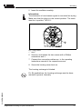
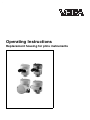
Operating Instructions
Replacement housing for plics instruments
Contents
Contents
1
About this document
1.1
1.2
1.3
2
.
.
.
.
.
.
.
.
.
.
.
.
.
.
.
.
.
.
.
.
.
.
.
.
.
.
.
.
General instructions. . . . . . . . . . . .
Mounting preparations . . . . . . . . . .
Dismounting steps existing housing
Mounting steps new housing . . . . .
.
.
.
.
.
.
.
.
.
.
.
.
.
.
.
.
.
.
.
.
.
.
.
.
.
.
.
.
.. 8
.. 8
.. 9
. . 11
Setup . . . . . . . . . . . . . . . . . . . . . . . . . . . . . . . 13
Instrument repair . . . . . . . . . . . . . . . . . . . . . . . 14
Dismounting
7.1
7.2
8
6
6
7
.
.
.
.
Maintenance
6.1
7
Configuration. . . . . . . . . . . . . . . . . . . . . . . . . .
Principle of operation . . . . . . . . . . . . . . . . . . . .
Storage and transport . . . . . . . . . . . . . . . . . . .
.
.
.
.
Setup
5.1
6
5
5
5
5
.
.
.
.
Mounting
4.1
4.2
4.3
4.4
5
..
..
..
..
Authorised personnel . . . . . . . .
Appropriate use. . . . . . . . . . . .
Safety information for Ex areas.
Environmental instructions . . . .
Product description
3.1
3.2
3.3
4
4
4
4
For your safety
2.1
2.2
2.3
2.4
3
Function . . . . . . . . . . . . . . . . . . . . . . . . . . . . .
Target group . . . . . . . . . . . . . . . . . . . . . . . . . .
Symbolism used . . . . . . . . . . . . . . . . . . . . . . .
Dismounting procedure . . . . . . . . . . . . . . . . . . 15
Disposal . . . . . . . . . . . . . . . . . . . . . . . . . . . . . 15
Supplement
8.1
Technical data. . . . . . . . . . . . . . . . . . . . . . . . . 16
31150-EN-050802
2
Replacement housing for plics instruments
About this document
1 About this document
1.1 Function
This operating instructions manual has all the information you
need for quick mounting and setup of a replacement
component. Please read this manual before you start setup.
1.2 Target group
This operating instructions manual is directed to trained
personnel. The contents of this manual should be made
available to these personnel and put into practice by them.
1.3 Symbolism used
Information, tip, note
This symbol indicates helpful additional information.
Caution, warning, danger
This symbol informs you of a dangerous situation that could
occur. Ignoring this cautionary note can impair the person and/
or the instrument.
Ex applications
This symbol indicates special instructions for Ex applications.
List
The dot set in front indicates a list with no implied sequence.
à
Action
This arrow indicates a single action.
1
Sequence
Numbers set in front indicate successive steps in a procedure.
31150-EN-050802
l
Replacement housing for plics instruments
3
For your safety
2 For your safety
2.1 Authorised personnel
All operations described in this operating instructions manual
must be carried out only by trained, specialised personnel
authorised by the operator. For safety and warranty reasons,
any internal work on the instruments must be carried out only
by personnel authorised by the manufacturer.
2.2 Appropriate use
Oscillator, emitting electronics, housing or process components are replacement components for existing sensors.
2.3 Safety information for Ex areas
Please note the Ex-specific safety information for installation
and operation in Ex areas. These safety instructions are part of
the operating instructions manual and come with the Exapproved instruments.
2.4 Environmental instructions
Protection of the environment is one of our most important
duties. That is why we have introduced an environment
management system with the goal of continuously improving
company environmental protection. The environment management system is certified acc. to DIN EN ISO 14001.
Please help us fulfil this obligation by observing the environmental instructions in this manual:
l
l
Chapter "Storage and transport"
Chapter "Disposal"
31150-EN-050802
4
Replacement housing for plics instruments
Product description
3 Product description
3.1 Configuration
Scope of delivery
The scope of delivery encompasses:
l
l
l
l
l
l
Components
Replacement housing with screwed cover
Locking ring
Check bracket
2 screws M3x5
2 lock washers 3.2 mm
Documentation
- this operating instructions manual
The housing consists of the basic body as well as a screwed
cover for the electronics or connection compartment.
Basic body and screwed cover are available in different
materials. Depending on the order, the screwed cover is
available with or without inspection window for the indicating
and adjustment module PLICSCOM.
1
Fig.
1
2
3
4
2
3
4
1: Versions of the replacement housing for plics instruments
Plastic
Stainless steel
Alu double chamber
Alu single chamber
3.2 Principle of operation
Area of application
The housing is suitable as replacement unit for the following
plics sensors:
l
31150-EN-050802
l
l
l
l
l
l
VEGAPULS series 60
VEGASON series 60
VEGAFLEX series 60
VEGABAR series 50 and 60
VEGASWING series 60
VEGAVIB series 60
VEGACAL series 60
Replacement housing for plics instruments
5
Product description
l
VEGACAP series 60.
3.3 Storage and transport
Packaging
Your instrument was protected by packaging during transport.
Its capacity to handle normal loads during transport is assured
by a test acc. to DIN EN 24180.
The packaging of standard instruments consists of environment-friendly, recyclable cardboard. For special versions, PE
foam or PE foil is also used. Dispose of the packaging material
via specialised recycling companies.
Storage and transport temperature
l
l
Storage and transport temperature see "Supplement Technical data - Ambient conditions"
Relative humidity 20 ... 85 %
31150-EN-050802
6
Replacement housing for plics instruments
Mounting
4 Mounting
4.1 General instructions
If the housing is defective, it can be replaced by the user.
In Ex applications, only a housing with appropriate Ex approval
must be used.
If there is no housing available on site, it can be ordered from
the responsible VEGA agency.
Assignment
The housings are suitable for all VEGA plics sensors in
respective version and signal output. First of all check by
means of the following overview if you have the suitable
housing.
The order number is stated on the delivery note of the
replacement housing.
4.2 Mounting preparations
Single chamber housing
The single chamber housing PLICSGEH.2... is suitable for all
instruments listed in chapter "3.2 Principle of operation". It is
available with the following approvals:
l
l
l
l
Double chamber housing
The double chamber housing PLICSGEH2K ... is suitable for
the instruments listed in chapter "3.2 Principle of operation",
except for VEGASON 64, 65, 66 as well as VEGASWING 60
and VEGAVIB 60. It is available with the following approvals:
l
l
l
31150-EN-050802
PLICSGEH...X (X = without approvals)
PLICSGEH...1 (1 = approval XM, CM, acc. to VEGA
product list)
PLICSGEH...2 (2 = approval DA, DM acc. to VEGA
product list)
PLICSGEH...3 (3 = approval GX, CK acc. to VEGA product
list)
l
l
PLICSGEH2K...X (X = without approvals)
PLICSGEH2K...1 (1 = approval XM, CX, CA,CM, CI, UX,
UF acc. to VEGA product list)
PLICSGEH2K...2 (2 = approval GX, CK acc. to VEGA
product list)
PLICSGEH2K...3 (3 = approval DX, DA, DM, DI acc. to
VEGA product list)
PLICSGEH2K...4 (4 = approval DX, DA, DK, UX acc. to
VEGA product list)
Replacement housing for plics instruments
7
Mounting
l
l
Double chamber housing
VEGASON 64, 65, 66
The double chamber housing PLICSGEH2K64 ... is only
suitale for VEGASON 64, 65 and 66. It is available with the
following approvals:
l
l
l
Tools
PLICSGEH2K...5 (5 = approval AX, AK acc. to VEGA
product list)
PLICSGEH2K...6 (6 = approvals GX acc. to VEGA product
list).
PLICSGEH2K64...X (X = without approvals)
PLICSGEH2K64...5 (5 = approval AX, AK acc. to VEGA
product list)
PLICSGEH2K64...6 (6 = approval GX acc. to VEGA
product list)
The following tools are required for dismounting the existing
housing and mounting the replacement housing:
l
l
l
magnetic Phillips head size 1
pliers for locking ring (version axle)
screwdriver 4 mm (only with stainless steel and Alu double
chamber housing)
4.3 Dismounting steps existing housing
First of all the electronics module is dismounted and the
existing housing removed.
Dismounting the electronics
The electronics module is located in the electronics compartment. The below illustrations show the respective position of
the electronics compartment in a single or double chamber
housing.
1
Fig. 2: Single chamber housing
1 Position of the electronics compartment
31150-EN-050802
8
Replacement housing for plics instruments
Mounting
1
Fig. 3: Double chamber housing
1 Position of the electronics compartment
Proceed as follows:
1
Switch off power supply
2
Remove the housing cover of the electronics compartment
as well as with Alu double chamber housing of the
connection compartment
3
Disconnect the connection cables acc. to the operating
instructions manual of the respective sensor
4
Loosen the two screws of the electronics module with the
Phillips head size 1
1
2
Fig. 4: Loosen the screws
1 Electronics module
2 Screws (2 pcs.)
5
31150-EN-050802
Remove the housing
Pull the electronics out by holding the opening levers.
Proceed as follows:
1
Loosen the screws of the check angle and the locking ring
with a screwdriver size 1
Replacement housing for plics instruments
9
Mounting
1
3
2
Fig. 5: Position of the screws and locking ring on the example of the plastic
housing
1 Screw check angle
2 Screw locking ring
3 Locking ring
2
Open the locking ring with the pliers and remove it
3
With Aluminium double chamber and stainless steel
housing loosen the screw on the socket
1
Fig. 6: Double chamber housing
1 Position of the screw
4
Remove the housing
4.4 Mounting steps new housing
Place the new housing back on.
2
With Aluminium double chamber or stainless steel housing
tighten the locking screw on the socket with a screwdriver
3
Tighten the screws of the check angle and the locking ring
with a screwdriver size 1
4
Insert the locking ring with the pliers
Replacement housing for plics instruments
31150-EN-050802
10
1
Mounting
5
Insert the oscillator carefully.
Information:
The electronics of most sensor types is connected via a plug.
Make sure that the plug is in the correct position. The notch
must be in position "18.00 h".
1
Fig. 7: Plug position
1 Notch
6
Screw in and tighten the two screws with a Phillips
screwdriver size 1.
7
Connect the connection cables acc. to the operating
instructions manual of the respective sensor
8
Screw the housing cover back on
The housing exchange is finished.
31150-EN-050802
For Ex applications, the housing exchange must be documented in general, internally.
Replacement housing for plics instruments
11
Setup
5 Setup
5.1 Setup
The setup is carried out acc. to the operating instructions
manual of the respective sensor.
31150-EN-050802
12
Replacement housing for plics instruments
Maintenance
6 Maintenance
6.1 Instrument repair
If it is necessary to repair the replacement component, please
proceed as follows:
You can download a return form (23 KB) from our homepage
www.vega.com under: "Services – Downloads – Forms and
Certificates – Repair form".
By doing this you help us carry out the repair quickly and
without having to call back for needed information.
l
l
l
31150-EN-050802
l
Print and fill out one form per instrument
Clean the instrument and pack it damage-proof
Attach the completed form and possibly also a safety data
sheet to the instrument.
Send the instrument to the respective address of your
agency. In Germany to the VEGA headquarters in
Schiltach.
Replacement housing for plics instruments
13
Dismounting
7 Dismounting
7.1 Dismounting procedure
Take note of chapters "Mounting" and "Connecting to power
supply" and carry out the listed steps in reverse order.
7.2 Disposal
The replacement component consists of materials which can
be recycled by specialised recycling companies. We have
purposely designed the electronic modules to be easily
separable. Mark the instrument as scrap and dispose of it
according to national government regulations (e.g. in Germany
acc. to electronic scrap ordinance).
Materials: see "Technical data"
If you cannot dispose of the instrument properly, please
contact us about disposal methods or return.
31150-EN-050802
14
Replacement housing for plics instruments
Supplement
8 Supplement
8.1 Technical data
Technical data
31150-EN-050802
are stated in the operating instructions manual of the appropriate sensor.
Replacement housing for plics instruments
15
VEGA Grieshaber KG
Am Hohenstein 113
77761 Schiltach
Germany
Phone +49 7836 50-0
Fax +49 7836 50-201
E-mail: [email protected]
www.vega.com
ISO 9001
All statements concerning scope of delivery, application,
practical use and operating conditions of the sensors and
processing systems correspond to the information available at the time of printing.
Technical data subject to alterations
31150-EN-050802