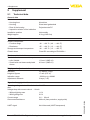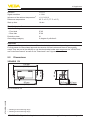
1
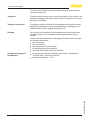
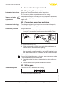
Operating Instructions
VEGADIS 176
Digital indicating instrument without external
energy for front panel mounting
Document ID: 47916
Contents
Contents
1 About this document
1.1Function............................................................................................................................ 4
1.2 Target group...................................................................................................................... 4
1.3 Symbols used................................................................................................................... 4
2 For your safety
2.1 Authorised personnel........................................................................................................ 5
2.2 Appropriate use................................................................................................................. 5
2.3 Warning about incorrect use.............................................................................................. 5
2.4 General safety instructions................................................................................................ 5
2.5 Safety label on the instrument........................................................................................... 5
2.6 CE conformity.................................................................................................................... 5
2.7 NAMUR recommendations............................................................................................... 6
2.8 Environmental instructions................................................................................................ 6
3 Product description
3.1 Configuration..................................................................................................................... 7
3.2 Principle of operation........................................................................................................ 7
3.3Operation.......................................................................................................................... 7
3.4 Packaging, transport and storage...................................................................................... 7
4Mounting
4.1 General instructions.......................................................................................................... 9
4.2 Mounting preparations...................................................................................................... 9
4.3 Mounting steps.................................................................................................................. 9
5 Connect to the signal circuit
5.1 Preparing the connection................................................................................................ 10
5.2 Connection technology and steps................................................................................... 10
5.3 Wiring plan...................................................................................................................... 10
5.4 Switch-on phase............................................................................................................. 12
6Setup
6.1 Indication and adjustment............................................................................................... 13
6.2 Parameter adjustment - Menu Setup............................................................................... 14
6.3 Parameter adjustment - Menu Diagnosis........................................................................ 15
6.4 Parameter adjustment - Menu Expert.............................................................................. 15
7 Maintenance and fault rectification
7.1Maintenance................................................................................................................... 17
7.2 Rectify faults.................................................................................................................... 17
7.3 How to proceed if a repair is needed............................................................................... 18
8Dismount
8.1 Dismounting steps.......................................................................................................... 19
8.2Disposal.......................................................................................................................... 19
2
VEGADIS 176 • Digital indicating instrument without external energy for front panel mounting
47916-EN-140903
9Supplement
9.1 Technical data................................................................................................................. 20
9.2Dimensions..................................................................................................................... 21
47916-EN-140903
Contents
Safety instructions for Ex areas
Please note the Ex-specific safety information for installation and operation in Ex areas. These safety instructions are part of the operating
instructions manual and come with the Ex-approved instruments.
Editing status: 2014-08-05
VEGADIS 176 • Digital indicating instrument without external energy for front panel mounting
3
1 About this document
1 About this document
1.1Function
This operating instructions manual provides all the information you
need for mounting, connection and setup as well as important instructions for maintenance and fault rectification. Please read this information before putting the instrument into operation and keep this manual
accessible in the immediate vicinity of the device.
1.2 Target group
This operating instructions manual is directed to trained specialist
personnel. The contents of this manual should be made available to
these personnel and put into practice by them.
1.3 Symbols used
Information, tip, note
This symbol indicates helpful additional information.
Caution: If this warning is ignored, faults or malfunctions can result.
Warning: If this warning is ignored, injury to persons and/or serious
damage to the instrument can result.
Danger: If this warning is ignored, serious injury to persons and/or
destruction of the instrument can result.
Ex applications
This symbol indicates special instructions for Ex applications.
•
→
1
SIL applications
This symbol indicates instructions for functional safety which must be
taken into account particularly for safety-relevant applications.
List
The dot set in front indicates a list with no implied sequence.
Action
This arrow indicates a single action.
Sequence of actions
Numbers set in front indicate successive steps in a procedure.
Battery disposal
This symbol indicates special information about the disposal of batteries and accumulators.
47916-EN-140903
4
VEGADIS 176 • Digital indicating instrument without external energy for front panel mounting
2 For your safety
2 For your safety
2.1 Authorised personnel
All operations described in this operating instructions manual must
be carried out only by trained specialist personnel authorised by the
plant operator.
During work on and with the device the required personal protective
equipment must always be worn.
2.2 Appropriate use
VEGADIS 176 is a digital indicating instrument for 4 … 20 mA circuits.
2.3 Warning about incorrect use
Inappropriate or incorrect use of the instrument can give rise to
application-specific hazards, e.g. vessel overfill or damage to system
components through incorrect mounting or adjustment.
2.4 General safety instructions
This is a state-of-the-art instrument complying with all prevailing
regulations and guidelines. The instrument must only be operated in a
technically flawless and reliable condition. The operator is responsible
for the trouble-free operation of the instrument.
During the entire duration of use, the user is obliged to determine the
compliance of the necessary occupational safety measures with the
current valid rules and regulations and also take note of new regulations.
The safety instructions in this operating instructions manual, the national installation standards as well as the valid safety regulations and
accident prevention rules must be observed by the user.
For safety and warranty reasons, any invasive work on the device
beyond that described in the operating instructions manual may be
carried out only by personnel authorised by the manufacturer. Arbitrary conversions or modifications are explicitly forbidden.
The safety approval markings and safety tips on the device must also
be observed.
2.5 Safety label on the instrument
The safety approval markings and safety tips on the device must be
observed.
47916-EN-140903
2.6 CE conformity
The device fulfills the legal requirements of the applicable EC guidelines. By affixing the CE marking, we confirm successful testing of the
product.
You can find the CE Certificate of Conformity in the download section
of our homepage.
VEGADIS 176 • Digital indicating instrument without external energy for front panel mounting
5
2 For your safety
2.7 NAMUR recommendations
NAMUR is the automation technology user association in the process
industry in Germany. The published NAMUR recommendations are
accepted as the standard in field instrumentation.
The device fulfills the requirements of the following NAMUR recommendations:
•
•
NE 21 – Electromagnetic compatibility of equipment
NE 43 – Signal level for malfunction information from measuring
transducers
For further information see www.namur.de.
2.8 Environmental instructions
Protection of the environment is one of our most important duties.
That is why we have introduced an environment management system
with the goal of continuously improving company environmental protection. The environment management system is certified according
to DIN EN ISO 14001.
Please help us fulfill this obligation by observing the environmental
instructions in this manual:
•
•
Chapter "Packaging, transport and storage"
Chapter "Disposal"
47916-EN-140903
6
VEGADIS 176 • Digital indicating instrument without external energy for front panel mounting
3 Product description
3 Product description
3.1 Configuration
Scope of delivery
The scope of delivery encompasses:
Application area
VEGADIS 176 is a digital indicating instrument for measured value
indication in 4 … 20 mA circuits. The measured value is displayed via
the LC display, the digital indication can be scaled. The instrument is
suitabe for front panel mounting.
•
•
•
Digital indicating instrument VEGADIS 176
Mounting material
Documentation
–– this operating instructions manual
–– Ex specific safety instructions (with Ex versions), if necessary
further certificates
3.2 Principle of operation
4
3
2
1
Fig. 1: Connection of VEGADIS 176 to the sensor
1 Voltage supply/Signal output sensor
2 VEGADIS 176
3 4 … 20 mA signal cable
4Sensor
Voltage supply
VEGADIS 176 is looped directly into the 4 … 20 mA circuits and
requires no separate external energy. Connection is carried out via a
detachable plug with spring-loaded terminals in the housing.
3.3Operation
47916-EN-140903
Adjustment is carried out via keys in the front plate of the instrument.
Packaging
3.4 Packaging, transport and storage
Your instrument was protected by packaging during transport. Its
capacity to handle normal loads during transport is assured by a test
based on ISO 4180.
The packaging of standard instruments consists of environmentfriendly, recyclable cardboard. For special versions, PE foam or PE
VEGADIS 176 • Digital indicating instrument without external energy for front panel mounting
7
3 Product description
foil is also used. Dispose of the packaging material via specialised
recycling companies.
Transport
Transport must be carried out in due consideration of the notes on the
transport packaging. Nonobservance of these instructions can cause
damage to the device.
Transport inspection
The delivery must be checked for completeness and possible transit
damage immediately at receipt. Ascertained transit damage or concealed defects must be appropriately dealt with.
Storage
Up to the time of installation, the packages must be left closed and
stored according to the orientation and storage markings on the
outside.
Unless otherwise indicated, the packages must be stored only under
the following conditions:
Storage and transport
temperature
•
•
•
•
•
•
•
Not in the open
Dry and dust free
Not exposed to corrosive media
Protected against solar radiation
Avoiding mechanical shock and vibration
Storage and transport temperature see chapter "Supplement Technical data - Ambient conditions"
Relative humidity 20 … 85 %
47916-EN-140903
8
VEGADIS 176 • Digital indicating instrument without external energy for front panel mounting
4 Mounting
4Mounting
4.1 General instructions
Mounting location, instal- The instrument is designed for use in a front panel. The installation
lation position
position is horizontal.
4.2 Mounting preparations
92mm (3 5/8")
92 mm
(3.62")
45 mm
(1.77")
Prepare panel cut-out 92 x 45 mm (3.62 x 1.77 in) according to illustration and DIN 43700. Max. panel thickness 13 mm (0.51 inch)
Required tools:
•
Slotted screwdriver
4.3 Mounting steps
Proceed as follows:
1. Insert the instrument from the front into the cut opening
1
2
3
2. Attach mounting clips laterally on the housing
47916-EN-140903
3. Tighten threaded rods steadily with the screwdriver
VEGADIS 176 • Digital indicating instrument without external energy for front panel mounting
9
5 Connect to the signal circuit
5 Connect to the signal circuit
Note safety instructions
Take note of safety
instructions for Ex
applications
5.1 Preparing the connection
Always keep in mind the following safety instructions:
•
Connect only in the complete absence of line voltage
In hazardous areas you must take note of the respective regulations,
conformity and type approval certificates of the sensors and power
supply units.
5.2 Connection technology and steps
Connection technology
The voltage supply and signal output are connected via the springloaded terminals in the housing.
Connection procedure
Proceed as follows:
1. Remove approx. 10 cm (4 in) of the cable mantle, strip approx.
1 cm (0.4 in) of insulation from the ends of the individual wires
2
3
Fig. 4: Connection steps 2 and 3
2. Solid cores as well as flexible cores with cable end sleeves are
inserted directly into the terminal openings.
3. In case of flexible cores without end sleeves, press the terminal
from above with a small screwdriver, the terminal opening is then
free. When the screwdriver is released, the terminal closes again.
Information:
You can find further information on the max. wire cross-section under
"Technical data/Electromechanical data"
4. Check the hold of the wires in the terminals by lightly pulling on
them
5. Connect screen to the potential equalisation terminal.
Terminal assignment
5.3 Wiring plan
The terminals are on the rear of the housing.
1
2
3
4
5
10
VEGADIS 176 • Digital indicating instrument without external energy for front panel mounting
47916-EN-140903
Fig. 5: Terminal assignment VEGADIS 176
5 Connect to the signal circuit
Terminal
Function
Polarity
Notes
1
Output sensor
+
Display with backlight
2
Output sensor
+
3
Output sensor
-
Bridged internally
with terminal 4
4
Input voltage sup- ply
Bridged internally
with terminal 3
5
Input voltage sup- +
ply
The terminal for the potential equalisation is also on the rear of the
instrument.
1
Fig. 6: Potential equalisation VEGADIS 176
1 Potential equalisation terminal
Connection to passive
sensors
1
2
3
4
5
+
+
– 2
1 –
Fig. 7: Wiring plan VEGADIS 176 to passive sensors
1 To the sensor
2 To power supply or the processing system
Connection to passive
sensors - with backlight
1
2
3
4
+
1 –
5
+
– 2
Fig. 8: Wiring plan VEGADIS 176 to passive sensors, with backlight
47916-EN-140903
1 To the sensor
2 To power supply or the processing system
VEGADIS 176 • Digital indicating instrument without external energy for front panel mounting
11
5 Connect to the signal circuit
Connection to active
sensors
1
2
3
4
5
4
5
+
1 –
Fig. 9: Wiring plan VEGADIS 176 to active sensors
1 To the sensor
Connection to active sensors - with backlight
1
2
3
+
1 –
Fig. 10: Wiring plan VEGADIS 176 to active sensors, with backlight
1 To the sensor
5.4 Switch-on phase
After connecting the instrument to voltage supply or after voltage
recovery, the instrument carries out a self-check for approx. 10 s and
then displays the following:
•
•
•
All display segments
Firmware version, e.g. 1.02.00
Status message, e.g. S901
Then the actual measured value will be displayed. You can find further
information of the presentation in chapter "Parameter adjustment Menu Setup".
47916-EN-140903
12
VEGADIS 176 • Digital indicating instrument without external energy for front panel mounting
6 Setup
6Setup
Display and adjustment
elements
6.1 Indication and adjustment
1
7
3
6
2
5
4
Fig. 11: Display and adjustment elements of VEGADIS 176
1
2
3
4
5
6
7
Symbol adjustment menu locked
Symbol error
Symbol upper/lower range
Adjustment keys
14-segment display for unit/TAG
Bargraph with marks for lower and upper range
5-digit 7-segment display for measured value
The adjustment is carried out via three buttons on the housing front.
Key
Function
Adjustment key
–– Invoke the adjustment menu
–– Confirm selection
–– Adjustment of parameters in the adjustment
menu
Plus/minus buttons
–– Selection and adjustment/change of values in the
adjustment menu
–– Pushing "-" and "+" simultaneously will cause a
reset to the nixt higher menu level without saving
the adjusted value (ESC)
47916-EN-140903
Adjustment system
The device setup can be locked with a 4-digit user code. When the
setup is locked, a lock symbol is displayed when invoking an adjustment parameter.
The adjustment functions of the process indicator are structured
in the following menus. The individual parameters and settings are
described in chapter "Setup".
The display in the 7-segment indication can only display figures and
not alphanumerical signal. Hence the procedure with number and text
parameters is different.
Number parameters
If an adjustment position contains only numbers as a paramter, then
the adjustment position is shown in the 14-segment display and the
VEGADIS 176 • Digital indicating instrument without external energy for front panel mounting
13
6 Setup
adjusted parameter in the 7-segment display. Push the "E" key for
editing and then enter the user code.
Text parameters
If the adjustment position contains text parameters, then first only
the adjustment position is displayed in the 14-segment display. After
pushing the "E" key again, the adjusted parameter is shown in the
14-segment display. For editing push the "+" key and finally enter the
user code.
Return
The return is carried out:
•
•
•
At the end of the individual menus and menu points with "Back"
and pushing the "E" key to the next higher menu level
After pushing "-" and "+" simultaneously (see table on top), to the
next higher menu level up to the measured value indication
Automatically 10 min. after the last key pressing to the measured
value indication
In all cases, the EXPRT menu is again locked.
Note:
If the adjustment menu is locked by a user code, the individual menus
and parameters can be displayed but not modified. To modify a parameter, the user coded has to be entered.
Adjustment menu
Setup - DECIM
The following table shows the menu structure:
Menu
Function
Description
SETUP
Setup
Fundamental device settings
DIAG
Diagnostics
Device information, indication of error messages
EXPRT
Expert
Expert settings for the
device setup. Editing
in the menu Expert is
protected through an
access code (Default
0000).
6.2 Parameter adjustment - Menu Setup
In this menu item you specify the number of decimal points for the
indication.
Value range: 0 DEC, 1 DEC, 2 DEC, 3 DEC, 4 DEC
Setup - SC__4
Example: SC__4 = 0.0 means display 0.0 with measurement current
4 mA. The unit selected under UNIT is used in the display.
Value range: -19 999 … 99 999
14
VEGADIS 176 • Digital indicating instrument without external energy for front panel mounting
47916-EN-140903
In this menu item you specify the 5-digit number value (number of
decimal points as set unter DECIM) for the scaling of the measured
value at 4 mA.
6 Setup
Setup - SC__20
In this menu item you specify the 5-digit number value (number of
decimal points as set unter DECIM) for the scaling of the measured
value at 20 mA.
Example: SC__20 = 100.0 means display 100.0 with measurement
current 20 mA. The unit selected under UNIT is used in the display.
Value range: -19 999 … 99 999
Setup - UNIT
In this menu item you select the unit for the display. By the adjustment "USER", a user-selectable unit can be entered in the parameter
"TEXT".
Value range: %, °C, °F, K, USER
Setup - TEXT
Diagnosis - AERR
By setting "USER" in "UNIT", a user-selectable unit can be entered.
Value range: Free text, 5-digit
6.3 Parameter adjustment - Menu Diagnosis
In this menu item, acutally occurring diagnosis messages (Actual
Error) are displayed. If the several message appear together, the message with the highest priority will be displayed.
Diagnosis - LERR
In this menu item, the last diagnosis message (Last Error) with the
highest priority is displayed.
Diagnosis - FWVER
In this menu item, the firmware version is displayed.
6.4 Parameter adjustment - Menu Expert
The menu Export contains in addition to all menu items from the
menu Setup also the submenus and menu items described, here.
When invoking the expert menu, the user code will be enquired
(UCODE, Default: 0000).
SYSTM - UCODE
With the user code, the device setup can be protected against unauthorized modifications. When the setup is locked, the lock symbol will
be displayed when invoking an adjustment parameter. With default
setting "0000", the user code is not active, i.e. parameters in the setup
can be modified without entering the code. For the expert menu, the
code must always be entered, also with default setting.
Value range: 0000 ... 9999
SYSTM - FRSET
Resetting the device setup to default values.
By selecting "YES" and confirming with the "E" key, the instrument will
be reset.
47916-EN-140903
Value range: YES, NO
The following table shows the default values after a reset:
VEGADIS 176 • Digital indicating instrument without external energy for front panel mounting
15
6 Setup
Menu
Submenu
Menu item
Default values
SETUP
-
DECIM
1 DEC
-
SC__4
0.0
-
SC__20
100.0
-
UNIT
%
-
TEXT
-
SYSTM
UCODE
0000
FRSET
NO
DECIM
1 DEC
SC__4
0.0
SC__20
100.0
UNIT
%
TEXT
-
CURVE
LINAR
NAMUR
YES
RNGLO
03.80
RNGHI
20.00
OFFST
0.0
EXPRT
INPUT
INPUT-CURVE
Selection of the linearization curve for the measurement current. With
this parameter the instrument can be adapted to a linear or square
measurement signal.
Value range: LINAR, SQRT
INPUT-NAMUR
Specification of the error limits according to standard NAMUR NE 43
INPUT-RNGLO
Lower range limit. If the measured current falls below this limit, an
error message is outputted.
Value range: YES, NO
Only visible with NAMUR = NO
Value range: 00.00 ... 99.99
INPUT-RNGHI
Upper range limit. If the measured current exceeds this limit, an error
message is outputted.
Only visible with NAMUR = NO
Value range: 00.00 ... 99.99
INPUT-OFFST
Value range: -19999 ... 99999
VEGADIS 176 • Digital indicating instrument without external energy for front panel mounting
47916-EN-140903
16
Entering an offset value for indication of the measured value.
7 Maintenance and fault rectification
7 Maintenance and fault rectification
7.1Maintenance
If the instrument is used properly, no special maintenance is required
in normal operation.
Causes of malfunction
7.2 Rectify faults
VEGADIS 176 offers maximum reliability. Nevertheless, faults can occur during operation. These may be caused by the following, e.g.:
•
•
•
•
Fault rectification
Check the 4 … 20 mA
signal
Sensor
Process
Voltage supply
Signal processing
The first measure is to check the sensor output signal according to
the operating instructions manual of the respective sensor. In many
cases the reasons can be determined this way and faults rectified.
System errors of VEGADIS 176 are displayed via the system error
message of the following chart:
Connect a multimeter in the suitable measuring range according to
the wiring plan.
Error code
Cause
Rectification
4 … 20 mA
signal missing
Wrong connection to
voltage supply
–– Check and correct, if necessary, according to chapter "Wiring plan"
No power supply
–– Check cables for breaks; repair if
necessary
Operating voltage
–– Check, adapt if necessary
too low or load resistance too high
In Ex applications, the regulations for the wiring of intrinsically safe
circuits must be observed.
47916-EN-140903
Error limits - NAMUR
NE 43
Sensor diagnosis
The instrument can be adjusted to error limits according to NAMUR
NE 43. If one of these values is violated, then the instrument displays
a diagnosis code.
Error limit with current Error
value I
Diagnosis code
I ≤ 3.6 mA
Lower range
F100
3.6 mA < I ≤ 3.8 mA
Unpermitted measured
value
S901
20.5 mA ≤ I < 21.0 mA
Unpermitted measured
value
S902
I > 21 mA
Upper range
F100
The instrument has diagnosis functions for the sensor. If an error is
detection, the instrument wil display a diagnosis code.
VEGADIS 176 • Digital indicating instrument without external energy for front panel mounting
17
7 Maintenance and fault rectification
Electronics diagnosis
Configuration diagnosis
24 hour service hotline
Diagnosis code
Short text
Rectification measure
F100
Sensor error
–– Check electrical wiring
–– Check sensor
–– Check sensor parameter
adjustment
S901
Input signal too low
S902
Input signal too high
–– Check sensor output on
defect and deviation of characteristic
–– Check sensor parameter
adjustment
The instrument has diagnosis functions for the own electronics. If an
error is detected, a diagnosis message will be displayed.
Diagnosis code
Short text
Rectification measure
F261
Electronics module
Replace electronics
F283
Memory content
–– Restart instrument
–– Carry out device reset
–– Replace electronics
F431
Factory calibration
Replace electronics
Diagnosis code
Short text
Rectification measure
M561
Display exceeded
Check scaling
Should these measures not be successful, please call in urgent cases
the VEGA service hotline under the phone no. +49 1805 858550.
The hotline is manned 7 days a week round-the-clock. Since we offer
this service worldwide, the support is only available in the English
language. The service is free, only standard call charges are incurred.
Reaction after fault rectification
Depending on the reason for the fault and the measures taken, the
steps described in chapter "Set up" may have to be carried out again.
7.3 How to proceed if a repair is needed
You can find a repair form as well as detailed information on how to
proceed at www.vega.com/downloads and "Forms and certificates".
By doing this you help us carry out the repair quickly and without having to call back for needed information.
If a repair is necessary, please proceed as follows:
•
18
Print and fill out one form per instrument
Clean the instrument and pack it damage-proof
Attach the completed form and, if need be, also a safety data
sheet outside on the packaging
Please contact the agency serving you to get the address for
the return shipment. You can find the agency on our home page
www.vega.com.
VEGADIS 176 • Digital indicating instrument without external energy for front panel mounting
47916-EN-140903
•
•
•
8 Dismount
8Dismount
8.1 Dismounting steps
Take note of chapters "Mounting" and "Connecting to power supply"
and carry out the listed steps in reverse order.
8.2Disposal
The display and adjustment module consists of materials which can
recycled by specialised recycling companies. We have purposely
designed the components to be easily separable.
WEEE directive 2002/96/EG
This display and adjustment module is not subject to the WEEE
directive 2002/96/EG and the respective national laws (in Germany,
e.g. ElektroG). Pass the display and adjustment module directly on
to a specialised recycling company and do not use the municipal
collecting points. These may only be used for privately used products
according to the WEEE directive.
Correct disposal avoids negative effects on humans and the environment and ensures recycling of useful raw materials.
Materials: see chapter "Technical data"
47916-EN-140903
If you have no way to dispose of the old instrument properly, please
contact us concerning return and disposal.
VEGADIS 176 • Digital indicating instrument without external energy for front panel mounting
19
9 Supplement
9Supplement
9.1
Technical data
General data
Materials
ƲƲ Housing front
Aluminium
ƲƲ Rear of the housing
Polycarbonate PC
ƲƲ Housing
ƲƲ Inspection window of the indication
Installation position
Weight approx.
Ambient conditions
Ambient temperature
ƲƲ Function range
ƲƲ Read area
Storage and transport temperature
Climatic class
Electromechanical data
Terminals for wire cross-section up to
ƲƲ solid, flexible
ƲƲ Strand with end sleeve and plastic
sleeve
Sheet steel galvanized
Horizontally
0.3 kg (0.661 lbs)
-40 … +60 °C (-40 … +140 °F)
-25 … +60 °C (-13 … +140 °F)
-40 … +85 °C (-13 … +185 °F)
Class B 2 according to EN 60654-1
1.5 mm² (AWG 16)
0.5 mm² (AWG 21)
Display and adjustment elements
Indication
LC display, 5-digit
Indication range
-19999 up to +99999
Height of figures
Adjustment elements
Signal and supply circuit
Operating voltage via 4 … 20 mA circuit
max.
17 mm (0.67 in)
3 keys (-/+/E)
30 V DC
Voltage drop with current value 4 … 20 mA
ƲƲ Without lighting max.
ƲƲ With lighting max.
Current range
HART signal
20
2.9 V
3.6 … 22 mA
200 mA (fuse protection, supply side)
Not influenced (HART-transparent)
VEGADIS 176 • Digital indicating instrument without external energy for front panel mounting
47916-EN-140903
Overcurrent resistance
1.0 V
9 Supplement
Deviation
Deviation1)
< 0.1 %
Influence of the ambient temperature2)
< 0.1 %/10 K
Signal resolution
Reference temperature
Start-up time
Electrical protective measures
Protection rating
ƲƲ Front side
ƲƲ Rear side
> 13 bit
25 °C ±5 °C (77 °C ±9 °C)
10 min.
IP 65
IP 20
Protection class
III
Overvoltage category
II, degree of pollution 2
Approvals
Instruments with approvals can have different technical specifications depending on the version.
For that reason the associated approval documents of these instruments have to be carefully
noted. They are part of the delivery or can be downloaded under www.vega.com via "VEGA Tools"
and "Instrument search" as well as via "Downloads" and "Approvals".
9.2Dimensions
96 mm
(3.78")
43 mm
(1.69")
110 mm
(4.33")
48 mm
(1.89")
VEGADIS 176
36,5 mm
(1.44")
4,5 mm
(0.18")
47916-EN-140903
Fig. 15: VEGADIS 176
1)
2)
Relating to the measuring range
Relating to the measuring range
VEGADIS 176 • Digital indicating instrument without external energy for front panel mounting
21
9 Supplement
9.3
Industrial property rights
VEGA product lines are global protected by industrial property rights. Further information see
www.vega.com.
Only in U.S.A.: Further information see patent label at the sensor housing.
VEGA Produktfamilien sind weltweit geschützt durch gewerbliche Schutzrechte.
Nähere Informationen unter www.vega.com.
Les lignes de produits VEGA sont globalement protégées par des droits de propriété intellectuelle. Pour plus d'informations, on pourra se référer au site www.vega.com.
VEGA lineas de productos están protegidas por los derechos en el campo de la propiedad industrial. Para mayor información revise la pagina web www.vega.com.
Линии продукции фирмы ВЕГА защищаются по всему миру правами на интеллектуальную
собственность. Дальнейшую информацию смотрите на сайте www.vega.com.
VEGA系列产品在全球享有知识产权保护。
进一步信息请参见网站<www.vega.com。
9.4Trademark
All the brands as well as trade and company names used are property of their lawful proprietor/
originator.
47916-EN-140903
22
VEGADIS 176 • Digital indicating instrument without external energy for front panel mounting
47916-EN-140903
Notes
VEGADIS 176 • Digital indicating instrument without external energy for front panel mounting
23
All statements concerning scope of delivery, application, practical use and operating conditions of the sensors and processing systems correspond to the information
available at the time of printing.
Subject to change without prior notice
© VEGA Grieshaber KG, Schiltach/Germany 2014
VEGA Grieshaber KG
Am Hohenstein 113
77761 Schiltach
Germany
Phone +49 7836 50-0
Fax +49 7836 50-201
E-mail: [email protected]
www.vega.com
47916-EN-140903
Printing date: