1
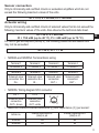
Operating instructions
(Safety-related part ATEX and IECEx)
Inductive NAMUR sensors
80001940/00
02/2014
NN504A
NN505A
UK
Remarks for safe use
in hazardous areas
Functions and features
Use in hazardous areas according to the classification
II 1G / 2G (Group II, category 1G / 2G, apparatus for gas atmosphere).
The requirements of the standards IEC 60079-0:2011 + Corr 2012, IEC 6007911:2011 and IEC 60079-26:2006 + Corr 2009 are met.
Use in hazardous areas according to the classification
II 1D (group II, category 1D, apparatus for dust atmosphere).
The requirements of the standards IEC 60079-0:2011 + Corr 2012, IEC 6007911:2011 and IEC 60079-26:2006 + Corr 2009 are met.
EC Type Test Certificate
BVS 14 ATEX E 005 X
IECEx type examination certificate
IECEx BVS 14.0005X
• Marking
II 1G Ex ia IIB T4 Ga
Ta: -25...70°C
II 2G Ex ia IIC T4 Gb
Ta: -25...70°C
II 1D Ex ia IIIB T135°C Da
Ta: -25...70°C
Installation / set-up
The units must only be installed, connected and set up by qualified staff. The
qualified staff must have knowledge of types of protection, regulations and
provisions for apparatus in hazardous areas.
Check whether the classification (see "Marking" above and marking on the unit) is
suitable for the application.
2
Sensor connection
Only to intrinsically safe certified circuits or evaluation amplifiers which do not
exceed the following maximum values of the units.
Ui = 15 V, Ii = 50 mA, Pi = 120 mW
Actuator wiring
Only to intrinsically safe certified circuits of solenoid valves that do not exceed the
following maximum values of the units. Also observe the technical data sheet.
Ui = 28 V, Ii = 250 mA,
Pi = 750 mW (up to 40 °C), Pi = 650 mW (up to 70 °C)
UK
For use in gas atmosphere (Group II), the following values are admissible and
may not be exceeded.
Ui = 28 V, Pi = 1.1 W
• NN504A and NN505A: Terminal block wiring
Terminal 1
A2 sensor 2
Terminal 2
L+ sensor 2
Terminal 3
A1 sensor 1
Terminal 4
L+ sensor 1
Terminal 5
Solenoid valve
connection Ex-i
IN +
Terminal 6
Solenoid valve
connection Ex-i
IN -
Terminal 7
Solenoid valve
connection
OUT +
Terminal 8
Solenoid valve
connection
OUT -
• NN505A: Wiring diagram M12 connector
Pin 1
Solenoid valve
connection
OUT + brown
Pin 2
Solenoid valve
connection
OUT - white
4
3
1
2
• Maximum effective internal inductance (Li) and capacitance (Ci) per sensor:
Article no.
NN504A
NN505A
Internal inductance Li
(total) in μH
130
130
Internal capacitance Ci
(total) in nF
60
60
3
Installation remarks / mounting
•
•
•
•
•
•
•
•
Adhere to the relevant national regulations and provisions.
The relevant installation regulations must be adhered to.
Protect the units efficiently against damage.
To avoid electrostatic charging, steps must be taken to ensure the equalisation
of potential of metal parts (plug housing, fixing elements, etc.).
Please use cable glands or screw plugs that guarantee at least housing
protection rating IP20 for connection. Using cable gland E12208 and protective
cap E12209 from ifm electronic, the housing reaches protection rating IP67
in case of correct installation. This combination is tested with regard to
electrostatics. If you use different cable glands or protective caps, please pay
attention to the electrostatics of this combination.
The M12 socket mounted to the NN505A is only for connection with the
actuator output.
Only use cables with an insulation resistance of at least 500 V between the
separate intrinsically safe circuits.
The units must not be installed in the partition between different zones.
Avoid electrostatic charging on housings and cables.
Maintenance / repair
The unit must not be modified nor can it be repaired. In case of a fault, please
contact the manufacturer.
Data sheets, EC declaration of conformity and EC type examination certificates
are available from the manufacturer on request.
To view the IECEx certificate online, please visit www.iecex.com.
4