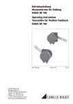
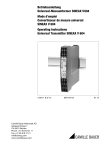
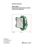
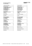
1
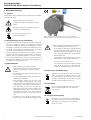
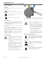
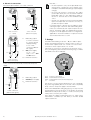
Betriebsanleitung
Messumformer für Stellung
KINAX SR709
Operating Instructions
Transmitter for Position Feedback
KINAX SR709
II 2 G
SR709 Bde
Camille Bauer AG
Aargauerstrasse 7
CH-5610 Wohlen/Switzerland
Phone +41 56 618 21 11
Fax +41 56 618 21 21
[email protected]
www.camillebauer.com
138 611-06
03.13
Bertriebsanleitung
KINAX SR709, Messumformer für Stellung
1. Sicherheitshinweise
II 2 G
1.1 Symbole
Die Symbole in dieser Anleitung weisen auf Risiken hin und haben
folgende Bedeutung:
Warnung bei möglichen Gefahren.
Nichtbeachtung kann zu Betriebsstörungen
führen.
Nichtbeachtung kann zu Betriebsstörungen
und Personenschäden führen.
Info für bestimmungsgerechte
Produkthandhabung.
Bild 1. Stellungs-Rückmelder KINAX SR 709, Anschlusshebel in
Ruhestellung nach unten gerichtet, entspricht Ausgangsstrom 0/4 mA.
1.2 Bestimmungsgemässe Verwendung
•
Der Stellungs-Rückmelder KINAX SR 709 (Bild 1) dient zum
Erfassen von Hüben an Ventilen, Drosselklappen, Schiebern
und anderen Stellgliedern und formt diese Messgrösse in einen
eingeprägten, dem Messwert proportionalen Gleichstrom um.
•
Das Gerät ist für den Einbau industrieller Anlagen vorgesehen
und erfüllt die Anforderungen nach EN 61010-1.
•
Geräteausführungen mit Explosionsschutz dürfen nur in den
geplanten Einsatzzwecken eingesetzt werden. Der Einsatz in
anderen explosionsgefährdeten Bereichen ist nicht zulässig.
•
Der Hersteller haftet nicht für Schäden, die auf unsachgemässe
Behandlung, Modifikationen oder nicht bestimmungsgemässe
Anwendungen zurückzuführen sind.
1.3 Inbetriebnahme
• Einbau, Montage, Installation und Inbetriebnahme des Gerätes muss ausschliesslich
durch eine qualifizierte Fachkraft ausgeführt
werden.
• Die Betriebsanleitung des Herstellers muss beachtet werden.
• Vor Inbetriebnahme der Anlage alle elektrischen
Verbindungen überprüfen.
• Wenn Montage, elektrischer Anschluss oder
sonstige Arbeiten am Gerät und an der Anlage
nicht fachgerecht ausgeführt werden, kann es zu
Fehlfunktionen oder Ausfall des Gerätes führen.
• Eine Gefährdung von Personen, eine Beschädigung der Anlage und eine Beschädigung von
Betriebseinrichtungen durch den Ausfall oder
Fehlfunktion des Gerätes muss durch geeignete
Sicherheitsmassnahmen ausgeschlossen werden.
• Das Gerät nicht ausserhalb der Grenzwerte betreiben, welche in der Anleitung angegeben sind.
2
• Geräteausführungen mit Explosionsschutz dürfen
nur in Betrieb genommen werden, wenn...
- die Angaben auf dem Typenschild des Gerätes
mit dem zulässigen EX-Einsatzbereich vor Ort
übereinstimmen (Gerätegruppe, Kategorie,
Zone, Temperaturklasse bzw. maximale Oberflächentemperatur)
- die Angaben auf dem Typenschild des Gerätes
mit dem Spannungsnetz übereinstimmen.
- das Gerät unbeschädigt ist und
- sichergestellt ist, dass keine explosionsfähige
Atmosphäre, Öle, Säure, Gase, Dämpfe, Strahlungen etc. bei der Montage vorhanden sind.
1.4 Reparaturen und Änderungen
Reparaturen und Änderungen sind ausschliesslich
durch den Hersteller auszuführen. Bei unsachgemässen Eingriffen in das Gerät erlischt der Garantieanspruch. Änderungen, die zur Verbesserung des
Produktes führen, behalten wir uns vor.
1.5 Entsorgung
Geräte und Bestandteile dürfen nur fachgerecht
und nach länderspezifischen Vorschriften entsorgt werden.
1.6 Transport und Lagerung
Die Geräte sind ausschliesslich in der Originalverpackung zu transportieren und zu lagern. Geräte
nicht fallen lassen oder grösseren Erschütterungen aussetzen.
Betriebsanleitung SR709 Bd – 03.13
Camille Bauer
2. Lieferumfang
5. Technische Daten
1 Stellungs-Rückmelder KINAX SR709
5.1 Messeingang
1 Betriebsanleitung deutsch, englisch
Messgrösse:
Weg, Hub
1 EG-Baumusterprüfbescheinigung, nur bei ATEX-Zulassung
Messbereich-Grenzen:
0 … 10 bis 0 … 140 mm
3. Anwendung
5.2 Hilfsenergie H
Der Stellungs-Rückmelder besteht aus einem KINAX DrehwinkelMessumformer und einem vorgeschalteten Getriebe, das einen
Weg in einen Drehwinkel 0 … 90° umsetzt. Beide Teile sind in
einem robusten Aluminiumguss-Gehäuse zusammengefasst,
dessen Form und Verbindungsteile zum Stellglied von der NAMUR
empfohlen wurden.
Gleich- und
Wechselspannung:
Tabelle 1:
10
20
Der Abgriff des Ventil-Hubes erfolgt durch einen geschlitzten Hebel.
Die Anpassung an Hübe zwischen 10 und 140 mm wird durch eine
äussere Hebelübersetzung und durch eine innere Zahnradübersetzung erreicht. Die äussere Hebelübersetzung lässt sich so einstellen,
dass die innere Schaltachse bei vollem Hub einen Drehwinkel von
ca. 90° durchläuft. Für diesen Drehwinkel von 90° ist der eingebaute
Messumformer KINAX 3W2 ausgelegt.
Nennspannungen UN
Toleranz-Angaben
24 … 60 V DC/AC
DC – 15 … + 33%
AC ± 15%
85 … 230 V DC/AC
möglich nur bei der
Standard-Ausführung, Nicht Ex,
mit Galvanischer Trennung,
mit Allstrom-Netzteil
(DC und 45 … 400 Hz)
Leistungsaufnahme:
< 0,9 W bzw. < 1,8 VA
Hilfsenergieeinfluss:
≤ 0,1% innerhalb der zulässigen
Hilfsenergie-Toleranz
Nur Gleichspannung1:
12 … 33 V
(möglich bei der Standard-Ausführung, Nicht Ex, ohne Galvanische
Trennung)
Bild 2. Minimale Hubeinstellung am Anschlusshebel.
12 … 30 V
(erforderlich bei der Ex-Ausführung,
Zündschutzart «Eigensicherheit»
Ex ia IIC T6 Gb, ohne Galvanische
Trennung)
140
88
Nennspannungen und ToleranzAngaben siehe «Tabelle 1»
Max. Restwelligkeit:
10% p.p.
Max. Stromaufnahme:
Ca. 5 mA + IA
Hilfsenergieeinfluss:
< 0,2% innerhalb der zulässigen
Hilfsenergie-Toleranz
In Zündschutzart Eigensicherheit Ex ia IIC nur zum Anschluss
an einen bescheinigten eigensicheren Stromkreis mit folgenden
Höchstwerte:
Bild 3. Maximale Hubeinstellung am Anschlusshebel.
max. Eingangsspannung Ui: 30V
4. Hauptmerkmale
• Weg - Hubmessung mit Messbereichgrenzen 0…10 bis
0…140mm
• Einstellung des Messbereiches durch Verändern der
Hebelübersetzung, Feinabgleich durch Potentiometer / Optimale Anpassung der Messspannen an individuelle Bedürfnisse
max. Eingangsstrom Ii:
160mA
max. Eingangsleistung Pi:
1W
max. innere Kapazität Ci:
10nF
max. innere Induktivität Li:
Ist vernachlässig bar klein
1
Gegen Falschpolung geschützt. Der niedrigste Spannungswert darf 12 V
nicht unterschreiten.
• Messausgang: Gleichstromsignal (eingeprägt, 2-, 3- oder
4-Drahtanschluss)
5.3 Messausgang
• Kapazitives Abtastsystem / Verschleissfrei
Ausgangsgrösse IA:
• Anbaugerät im Feldgehäuse aus Aluminiumguss mit
NAMUR- Anbausatz für Stellglieder
Eingeprägter Gleichstrom
proportional zum Messwert
Nullpunktvariation:
Ca. ± 5%
Endwertvariation:
Ca. + 5 / –30%
Strombegrenzung:
IA max. 40 mA
Normbereiche:
0…1 mA,
3- oder 4-Drahtanschluss
• Mit Explosionsschutz „Ex ia IIC T6 Gb”, nach ATEX und IECEx
lieferbar
0…5 mA,
3- oder 4-Drahtanschluss
0…10 mA,
Camille Bauer
Betriebsanleitung SR709 Bd – 03.13
3
3- oder 4-Drahtanschluss
Prüfspannung:
2,2 kVeff, 50 Hz, 1 Min.
zwischen…
… Hilfsenergie und Gehäuse
… Hilfsenergie und Messausgang
(bei DC/AC-Hilfsenergie, mit Galvanischer Trennung, mit Allstrom-Netzteil)
4…20 mA, 2-Drahtanschluss oder
0…20 mA, 3- oder 4-Drahtanschluss
(durch Potentiometer einstellbar)
4…20 mA,
3- oder 4-Drahtanschluss
500 Veff, 50 Hz, 1 Min.
alle elektrischen Anschlüsse gegen
Gehäuse (bei DC-Hilfsenergie, ohne
Galvanische Trennung)
0…20 mA, 4-Drahtanschluss
Nicht-Normbereiche:
0…> 1,00 bis 0…< 20 mA
3- oder 4-Drahtanschluss
Aussenwiderstand (Bürde):
Rext max. [kΩ] =
12 V
IA [mA]
(bei Geräten mit DC/AC-Hilfsenergie
durch Allstrom-Netzteil, mit Galvanischer Trennung)
Rext max. [kΩ] =
Zul. Gleichtaktspannung:
100 V, 50 Hz
Gehäuseschutzart:
IP 54 nach EN 60529
5.7 Umgebungsbedingungen
Klimatische
Beanspruchung:
Standard Ausführung:
Temperatur – 25 bis + 70 °C
Rel. Feuchte im Jahresmittel ≤ 90%
oder
H [V] – 12 V
IA [mA]
(bei Geräten mit DC-Hilfsenergie, ohne
Galvanische Trennung)
Ausführung mit erhöhter Klimafestigkeit:
Temperatur -40 bis + 70 °C
Rel. Feuchte im Jahresmittel ≤ 95%
IA = Ausgangssignal-Endwert
Restwelligkeit des
Ausgangsstromes:
< 0,3% p.p.
Ex-Ausführung:
Temperatur -40 bis + 55 °C bei T6
bzw. -40 bis + 70 °C bei T5
bzw. -40 bis + 75 °C bei T4
5.4 Genauigkeitsangaben
Linearitätsfehler:
≤ 0,5%
5.5 Einbauangaben
Material:
Metall (Alu)
Gebrauchslage:
Beliebig
Gewicht:
ca. 1,1 kg
Befestigung:
Unmittelbare Befestigung
oder
Befestigung mit NAMUR-Anbausatz
(siehe Bilder 7 und 8)
Anschlüsse:
Betriebshöhe:
Transport- und
Lagerungstemperatur:
2000 m max.
Vibrationsfestigkeit:
5 g je 2 h in 3 Richtungen
f ≤ 200 Hz
Schockfestigkeit:
3x50 g je 10 Stösse
in allen Richtungen
5.8 Betrieb in explosionsgefährdeten Bereichen
Gasexplosionsschutz:
2 Stopfbuchsen PG 11 aus Metall
Kennzeichnung:
Zum Anschliessen der elektrischen Leitungen befinden sich in dem
Rückenteil (Haube) 4 Schraubklemmen und 1 Erdungsklemme.
Rückenteil
(Haube)
Zündschutzart:
Schraubklemmen
Gruppe nach
EN 60079-0:2012: II
Erdungsklemme
Stopfbuchsen
Bild 4. KINAX SR709 mit Schraubklemmen und Stopfbuchsen.
• Der Einsatz in anderen explosionsgefährdeten Bereichen ist
nicht zulässig.
• An Betriebsmittel die in explosionsgefährdeten Bereichen eingesetzt werden, darf keine Veränderung vorgenommen werden.
Bei der Festlegung des Montageortes (Messortes) ist
zu berücksichtigen, dass die Angaben unter «Umgebungsbedingungen», Abschnitt «5. Technische Daten»,
eingehalten werden.
5.6 Vorschriften
Störfestigkeit:
EN 61000-6-2
4
IECEx:
IEC60079-0:2011
IEC60079-11:2011-06
ia
Temperaturklasse: T6
Deckel
EN 61000-6-3
Ex ia IIC T6 Gb
Normkonformität: ATEX:
EN 60079-0:2012
EN 60079-11:2012
Die Schraubklemmen eignen sich für max. 1,5 mm2 Drahtquerschnitte und sind nach dem Entfernen des Deckels zugänglich.
Störaussendung:
– 40 bis + 80 °C
Betriebsanleitung SR709 Bd – 03.13
Geräte mit Explosionsschutz sind entsprechend
den Angaben in der Betriebsanleitung zu betreiben. Die für die Verwendung bzw. den geplanten
Einsatzzweck geltenden Gesetze, Richtlinien und
Normen sind zu beachten.
Camille Bauer
5.9 Mass-Skizzen
98
105
70$
M6
8,1
25
+0
,
0 1
90
104
70
15,5
130
PG 11
31
18
2
14
Bild 5. KINAX SR709, Lage des Anschlusshebels bei Ruhestellung nach unten gerichtet, entspricht Ausgangsstrom 0/4 mA.
25
98
8,1
+0
,
0 1
105
90
70$
104
70
M6
15.5
130
PG 11
31
18
2
14
Bild 6. KINAX SR709, Lage des Anschlusshebels bei Ruhestellung nach oben gerichtet, entspricht Ausgangsstrom 0/4 mA.
Camille Bauer
Betriebsanleitung SR709 Bd – 03.13
5
2 Befestigungsbügel
oder
Schraube M8
Ø
–
35
70
20
90
Anbaulasche
Bild 7. KINAX SR709, Anbau nach NAMUR-Empfehlung.
105
32
43
Ø
6,5
20
13
90
130
48
5
–3
43
20
9
80
90
4
12
Bild 8. NAMUR-Anbausatz.
6
Betriebsanleitung SR709 Bd – 03.13
Camille Bauer
6. Elektrische Anschlüsse
Es ist zu beachten, …
2-, 3- oder 4-Drahtanschluss ohne Galvanische Trennung
… dass die Daten, die zur Lösung der Messaufgabe
erforderlich sind, mit denen auf dem Typenschild des
KINAX 3W2 übereinstimmen (Range/Messeingang,
Output/Messausgang, Supply Voltage/Hilfsenergie)!
–
+
21
21
43
43
+
+
–
Brücke
… dass der Gesamtwiderstand in der Messausgangsleitung (in Serie geschaltete Empfangsgeräte plus
Leitung) den maximalen Aussenwiderstand Rext. max.
nicht überschreitet! Rext. max. siehe «Messausgang»,
Abschnitt «5. Technische Daten»!
–
… dass bei der Verlegung der Messausgangsleitung
verdrillte Kabel verwendet werden und diese möglichst
getrennt von Starkstromleitungen zu verlegen sind!
+
Rext
Rext
+
–
–
+
–
A
A und H
Im übrigen landesübliche Vorschriften bei der Installation
und Auswahl des Materials der elektrischen Leitungen
befolgen!
+
H
+
–
43
21
–
+
Bei Geräten in der Zündschutzart «Eigensicherheit» mit
eigensicherem Messausgang sind zusätzlich die Angaben
der Ex-Bescheinigung sowie die nationalen Vorschriften
für die Errichtung von elektrischen Anlagen in explosionsgefährdeten Bereichen zu berücksichtigen!
3-Drahtanschluss
(diverse mA-Signale)
2-Drahtanschluss
(4 … 20 mA)
A
= Messausgang
als 2-Drahtanschluss
(4…20 mA, Signal im
Mess-Speise-Kreis)
als 3- oder 4-Drahtanschluss (diverse
mA-Signale)
H
+
Rext
–
+
A
–
H
= DC-Hilfsenergie
H = 12 … 33 V
bzw. H = 12 … 30 V
bei Ex-Ausführung
7. Einstell-Elemente
Messumformer mit dem Bestell-Code 709 – ..D (siehe «Tabelle
2: Aufschlüsselung der Varianten») sind sowohl für den 2-Drahtanschluss mit dem Ausgangsstrom 4…20 mA als auch für den
3- bzw. 4-Drahtanschluss mit dem Ausgangsstrom 0…20 mA
geeignet.
Bei einem allfälligen Wechsel im Anschliessen des Gerätes
(siehe «6. Elektrische Anschlüsse») müssen jedoch Anfangs- und
Endwert des Messbereiches, ZERO und SPAN, neu eingestellt
werden.
Rext = Aussenwiderstand
4-Drahtanschluss
(diverse mA-Signale)
4-Drahtanschluss mit Galvanischer Trennung, mit Allstrom-Netzteil
–
21
–
43
+
+
Rext
A
Span
S1
A
= Messausgang
H
= AC/DC-Hilfsenergie
Rext = Aussenwiderstand
+
–
Zero
+
–
~ ~
H
4-Drahtanschluss
(diverse mA-Signale)
Bild 9.
ZERO
SPAN
S1
Lage der Einstell-Elemente
= Potentiometer für Nullpunkt
= Potentiometer für Messbereich-Endwert
= Nicht eingebaut
In diesem Abschnitt wird die genaue Einstellung, der Feinabgleich, sowohl des Anfangswertes (Nullpunkt/ZERO) als auch
des Endwertes (Spanne/SPAN) behandelt.
Messumformer in Betrieb nehmen. Dazu einfach die Hilfsenergie
einschalten.
Die ZERO/SPAN-Dichtungsstopfen (4) herausziehen (Bild 10,
links). Messobjekt in Nullstellung bringen, d.h. in die Position,
in der der KINAX 3W2 den Ausgangsstrom 0 mA (bei einem 3oder 4-Drahtanschluss) bzw. 4 mA (bei dem 2-Drahtanschluss)
ausgeben soll.
Danach Potentiometer «ZERO» (Bild 10, rechts) mit einem
Uhrmacher-Schraubenzieher (Ø 2,3 mm) so drehen, dass genau
der gewünschte Ausgangsstrom fliesst.
Camille Bauer
Betriebsanleitung SR709 Bd – 03.13
7
Danach wieder eine Kontrolle des Nullpunktes vornehmen, allenfalls mit dem ZERO-Potentiometer korrigieren und nochmal den
Endwert prüfen.
8. Elektrische Inbetriebnahme
(4)
• Bei Verbrauchern mit hohen Störpegeln separate Spannungsversorgung für das Gerät bereitstellen.
• Die gesamte Anlage EMV gerecht installieren. Einbauumgebung und Verkabelung können die EMV des Gerätes beeinflussen.
Bild 10. Einstell-Elemente «ZERO», «SPAN» und «S1»
Links: Einstell-Elemente durch Dichtungsstopfen (4) abgedeckt
Rechts: Einstell-Elemente zugänglich
Sodann Messobjekt in Endlage drehen, d.h. in die Stellung, in der
der KINAX 3W2 den ihm zugedachten Ausgangsstrom-Endwert,
siehe Typenschild, haben soll.
Potentiometer «SPAN» mit dem erwähnten Schraubenzieher derart
drehen, dass genau der gewünschte Ausgangsstrom-Endwert
abgegeben wird.
• Für Ausführungen mit Explosionsschutz:
Für das Errichten und Betreiben sind die Vorschriften
gemäss EN60079-14, das Gerätesicherheitsgesetz,
die allgemein anerkannten Regeln der Technik und
diese Betriebsanleitung massgebend.
9. Wartung
Das Gerät arbeitet wartungsfrei. Reparaturen dürfen nur von
autorisierten Stellen ausgeführt werden.
10. Tabelle 2: Aufschlüsselung der Varianten
*Sperrcode
Bezeichnung
KINAX SR 709
unmöglich
bei Sperrcode
Bestell-Code 709 - xxxx xx
Artikel-Nr./
Merkmal
709 –
Merkmale, Varianten
1. Ausführung
Standard, Messausgang nicht eigensicher
A
1
Ex ia IIC T6 Gb, Messausgang eigensicher, ATEX
B
2
Ex ia IIC T6, Messausgang eigensicher, FTZU Tschechien
B
6
EEx ia IIC T6, Messausgang eigensicher, Ungarn
B
7
Sonstige Ausführungen auf Anfrage
B
9
Ausführung IECEx Ex ia IIC T6 Gb
B
A
2. Montagelage
Lage des Hebels bei Ruhestellung:
Unten, enspricht 0/4 mA (normal)
0
Oben, entspricht 0/4 mA
1
Nachträgliche Änderung nicht möglich!
3. Ausgangssignal (Messausgang)
0 … 1 mA / 3- oder 4-Drahtanschluss
A
0 … 5 mA / 3- oder 4-Drahtanschluss
B
0 … 10 mA / 3- oder 4-Drahtanschluss
C
4 … 20 mA / 2-Drahtanschluss oder
0 … 20 mA / 3- oder 4-Drahtanschluss (mit Potentiometer einstellbar)
C
D
4 … 20 mA / 3- oder 4-Drahtanschluss
E
0 … 20 mA / 4-Drahtanschluss
Nur in Ausführung Standard mit DC/AC-Hilfsenergie (Allstrom-Netzteil)
D
B
F
Nichtnorm, 3- oder 4-Drahtanschluss
0 … > 1,00 bis 0 … < 20
[mA]
Z
Hilfsenergie DC/AC mit Galvanischer Trennung,
zwingend mit 4-Drahtanschluss,
DC-Hilfsenergie ohne Galvanische Trennung,
mit (2-), 3- oder 4-Drahtanschluss.
Bei 2-Drahtanschluss nur Zeile D möglich, kombiniert mit Hilfsenergie 12 … 33 (30) V DC!
8
Betriebsanleitung SR709 Bd – 03.13
Camille Bauer
*Sperrcode
Bezeichnung
KINAX SR 709
unmöglich
bei Sperrcode
Bestell-Code 709 - xxxx xx
Artikel-Nr./
Merkmal
709 –
Merkmale, Varianten
4. Hilfsenergie
24 … 60 V DC/AC, mit Galvanischer Trennung, mit Allstrom-Netzteil
E
BC
1
85 … 230 V DC/AC, mit Galvanischer Trennung, mit Allstrom-Netzteil
E
BC
2
12 … 33 V DC, ohne Galvanische Trennung
F
BD
A
12 … 30 V DC (Ex), ohne Galvanische Trennung
F
AD
B
Zeilen 1, 2 und A nur bei Ausführung Standard
Zeilen 1 und 2: DC/AC-Hilfsenergie bei Ausgangssignal «Auswahl-Kriterium 3, Zeile D» nicht möglich!
5. Klimatische Beanspruchung
Normale Klimafestigkeit
0
Erhöhte Klimafestigkeit bei der Standard-Ausführung,
ohne Galvanische Trennung
Temperatur – 40 bis + 70 °C,
relative Feuchte im Jahresmittel ≤ 95% statt ≤ 90%
BE
1
Erhöhte Klimafestigkeit bei der Standard-Ausführung,
mit Galvanischer Trennung, mit Allstrom-Netzteil
Temperatur – 40 bis + 70 °C,
relative Feuchte im Jahresmittel ≤ 95% statt ≤ 90%
BF
2
Erhöhte Klimafestigkeit bei der Ex-Ausführung,
ohne Galvanische Trennung
Temperatur – 40 bis + 55 °C bei T6 bzw. – 40 bis + 70 °C bei T5 bzw. – 40 bis + 75 °C bei T4,
relative Feuchte im Jahresmittel ≤ 95% statt ≤ 90%
AE
3
6. Anbausatz
Ohne Anbausatz
0
Mit NAMUR-Anbausatz Nr. 866 288
1
* Zeilen mit Buchstaben unter «unmöglich» sind nicht kombinierbar mit vorgängigen Zeilen mit gleichem Buchstaben unter «Sperrcode».
Camille Bauer
Betriebsanleitung SR709 Bd – 03.13
9
11. Konformitätserklärung
EG / IEC KONFORMITÄTSERKLÄRUNG
EC / IEC DECLARATION OF CONFORMITY
Dokum ent -Nr. /
Docum ent . No. :
Herst el l er/
Manuf act urer:
Anschri f t /
Address:
Produkt bezei c hnung/
Product nam e:
T yp / T ype:
SR709_CE-ko n f. DO C
Cami l l e Bau er AG
Swi t zerl and
Aarg au erstrasse 7
CH-5610 W ohl en
Messu mfo rmer fü r Dreh w i n kel
T ransm i t t er f or angul ar posi t i on
Ki n ax SR709
D as b ez ei c h n et e P r od u k t s t i m m t m i t d en V or s c h r i f t en f ol g en d er E u r op äi s c h er R i c h t l i n i en
ü b er ei n , n ac h g ewi es en d u r c h d i e E i n h al t u n g f ol g en d er N o r m en :
T h e ab ove m en t i on ed p r od u c t h as b een m an u f ac t u r ed ac c or d i n g t o t h e r eg u l at i on s of t h e f ol l owi n g E u r op ean d i r ec t i ves p r oven t h r ou g h c om p l i an c e wi t h t h e f ol l owi n g s t a n d ar d s :
Ri c h t l i n i e / Di r e c t i v e
No r m / St a n d a r d
2 0 0 4 / 1 0 8 / EG ( EC)
El ek t r o m a g n et i s c h e Ver t r ä g l i c h k ei t - EMV - Ri c h t l i n i e
El ec t r o m a g n et i c c o m p a t i b i l i t y - EMC d i r ec t i v e
EN 6 1 0 0 0 - 6 - 3 : 2 0 0 7
F a c h g r u n d n o r m en - St ö r a u s s en d u n g f ü r W o h n b er ei c h , G es c h ä f t s - u n d G ewer b eb er ei c h e s o wi e Kl ei n b et r i eb e
G en er i c s t a n d a r d s - Em i s s i o n s t a n d a r d f o r r es i d en t i a l , c o m m er c i a l a n d l i g h t i n d u s t r i a l en v i r o n m en t s
EN 6 1 0 0 0 - 6 - 2 : 2 0 0 5
F a c h g r u n d n o r m en - St ö r f es t i g k ei t f ü r I n d u s t r i eb er ei c h e
G en er i c s t a n d a r d s - I m m u n i t y f o r i n d u s t r i a l en v i r o n m en t s
Prüfungen / Tests
I EC
I EC
I EC
I EC
I EC
Ri c h t l i n i e / Di r e c t i v e
2 0 0 6 / 9 5 / EG ( EC)
El ek t r i s c h e Bet r i eb s m i t t el zu r Ver wen d u n g i n n er h a l b b es t i m m t er Sp a n n u n g s g r en zen – Ni ed er s p a n n u n g s r i c h t l i n i e – CE- Ken n zei c h n u n g : 9 5
El ec t r i c a l eq u i p m en t f o r u s e wi t h i n c er t a i n v o l t a g e l i m i t s – L o w Vo l t a g e D i r ec t i v e – At t a c h m en t o f CE m a r k i n g : 9 5
EN 6 1 0 1 0 - 1 : 2 0 0 1
Si c h er h ei t s b es t i m m u n g en f ü r el ek t r i s c h e Mes s - , St eu er - , Reg el - u n d L a b o r g er ä t e – T ei l 1 : Al l g em ei n e An f o r d er u n g en
Sa f et y r eq u i r em en t s f o r el ec t r i c a l eq u i p m en t f o r m ea s u r em en t , c o n t r o l a n d
l a b o r a t o r y u s e – Pa r t 1 : G en er a l r eq u i r em en t s
No r m / St a n d a r d
61000-4-2
61000-4-3
61000-4-4
61000-4-5
61000-4-6
EN 5 5 0 1 1
D i e exp l os i on s g es c h ü t z t e A u s f ü h r u n g s t i m m t m i t f ol g en d er R i c h t l i n i e ü b er ei n :
T h e exp l os i on p r ot ec t ed var i an t ac c or d s t o t h e f ol l owi n g d i r ec t i ve:
Ri c h t l i n i e / Di r e c t i v e
9 4 / 9 / EG ( EC)
h t t p : / / www. i e c e x . c o m / r u l e s . h t m
G er ät e u n d S c h u t z s ys t em e z u r b es t i m m u n g s g em äß en V er wen d u n g i n exp l os i on s g ef äh r d et en B er ei c h en
E q u i p m en t an d p r ot ec t i ve s ys t em s i n t en d ed f or
u s e i n p ot en t i al l y exp l os i ve at m os p h er es
No r m / St a n d a r d
Na c h we i s / Pr o o f
O r t , Da t u m /
Pl a c e, d a t e:
EN 6 0 0 7 9 - 0 : 2 0 1 2 / - 1 1 : 2 0 1 2
I EC 6 0 0 7 9 - 0 : 2 0 1 1 / - 1 1 : 2 0 1 1 - 0 6
E xp l os i on s f äh i g e A t m os p h är e / E xp l os i ve at m os p h er es –
- 0 : G er ät e - A l l g em ei n e A n f or d er u n g en / G en er al r eq u i r em en t s
- 1 1 : G er ät es c h u t z d u r c h E i g en s i c h er h ei t " i " /
E q u i p m en t p r ot ec t i on b y i n t r i n s i c s af et y " i "
E xp l os i ve at m os p h er es –
- 0 : G en er al r eq u i r em en t s
- 1 1 : E q u i p m en t p r ot ec t i on b y i n t r i n s i c
s af et y " i "
Z EL M 1 0 AT EX 0 4 2 7 X
I ECEx Z L M 1 2 . 0 0 0 8 X
N ot i f i ed B od y N o. 0 1 0 2 : P T B
D - 3 8 1 1 6 B r au n s c h wei g ,
IECEx QAR: PTB
D - 3 8 1 1 6 B r au n s c h wei g ,
W o h l en , 2 7 . Mä r z 2 0 1 3
Un t er s c h r i f t / s i g n a t u r e:
M. Ul r i c h
10
J . Br em
Betriebsanleitung SR709 Bd – 03.13
Camille Bauer
Operating Instructions
KINAX SR709, Transmitter for Position Feedback
1. Safety instructions
II 2 G
1.1 Symbols
The symbols in these instructions point out risks and have the
following meaning:
Warning in case of risks.
Non-observance can result in malfunctioning.
Non-observance can result in malfunctioning
and personal injury.
Information on proper product handling.
Fig. 1. Position feedback transmitter KINAX SR 709 showing the operating
lever in the lower zero position, corresponding output current 0/4 mA.
1.2 Intended use
• The position feedback transmitter KINAX SR 709 (Fig. 1) is used
to measure and transmit linear displacement (stroke) on various
types of control valves and other control devices. The output is
a load independent DC signal.
• Operation of device versions with explosion
protection is only permissible when...
- the details on the type label of the device
match the on-site conditions for the permissible Ex area in use (group of equipment,
equipment category, zone, temperature
class or maximum surface temperature)
• The angular position transmitter is not intended to measure
rotation speed.
• The device is intended for installation in industrial plants and
meets the requirements of EN 61010-1.
- the details on the type label of the device
match the electrical supply network
• Device versions with explosion protection may only be used in
the planned purposes. The operation in other explosive atmospheres is not permissible.
- the device is undamaged and
- it has been checked that there is no explosive atmosphere, oils, acids, gases, vapors,
radiation etc. present during installation.
• Manufacturer is not liable for any damage caused by inappropriate handling, modification or any application not according
to the intended purpose.
1.4 Repair work and modifications
1.3 Commissioning
Repair work and modifications shall exclusively
be carried out by the manufacturer. In case of
any tampering with the device, the guaranty claim
shall lapse. We reserve the right of changing the
product to improve it.
• Installation, assembly, setup and commissioning
of the device has to be carried out exclusively
by skilled workers.
• Observe manufacturer’s operating instructions.
• Check all electric connections prior to commissioning the plant.
• If assembly, electric connection or other work
on the device and the plant are not carried out
properly, this may result in malfunctioning or
breakdown of the device.
• Safety measures should be taken to avoid any
danger to persons, any damage of the plant and
any damage of the equipment due to breakdown
or malfunctioning of the device.
• Do not operate the device outside of the limit
values stated in the operating instructions.
Camille Bauer
1.5 Disposal
The disposal of devices and components may
only be realised in accordance with good professional practice observing the country-specific
regulations.
1.6 Transport and storage
Transport and store the devices exclusively in
their original packaging. Do not drop devices or
expose them to substantial shocks.
Operating Instructions SR709 Be – 03.13
11
2. Scope of delivery
5.2 Power supply H
1 Postion Feedback Transmitter KINAX SR709
DC und AC voltage:
1 Operating instructions in German and English
Table 1:
1 Type examination certificate, only with ATEX-approval
3. Application
Nominal voltages and tolerances
see “Table 1”
Nominal voltages UN
Tolerances
24 … 60 V DC/AC
DC – 15 … + 33%
AC ± 15%
85 … 230 V DC/AC
The position feedback transmitter consists of a KINAX angle
transmitter and a reduction gear which converts a linear movement into an angle of rotation of 0 … 90°. Both parts are
contained in a robust cast aluminium housing. The mounting
part to the control valve is based on NAMUR recommendations,
(standards working group for measuring and process control in
the chemical industry).
20
DC voltage only1:
140
< 0.9 W resp. < 1.8 VA
≤ 0.1% within the admissible power
supply tolerance
12 … 33 V
(possible with standard version, nonEx, without electric isolation)
12 … 30 V
(necessary with Ex version, type of
protection “Intrinsic safety”
Ex ia IIC T6 Gb, without electric
isolation)
Max. residual ripple:
10% p.p.
Max. current consumption:
Approx. 5 mA + IA
< 0.2% within the admissible power
supply tolerance
Protection intrinsic safety Ex ia IIC only for connection to
certified intrinsically safe circuit with the following maximum
values:
[5.512]
88
Power supply effect
on accuracy:
Power supply effect
on accuracy:
Fig. 2. Operating lever set for minimum operating angle.
[3.464]
Power consumption:
[0.787]
10 [0.393]
The pick-up of the stroke movement is made by means of a slotted
lever. The adaption to strokes between 10 and 140 mm is made
with an external lever transmission and by an internal gear ratio.
The external lever transmission can be adjusted in such a way, that
the internal cam shaft makes an angle of rotation of approx. 90° for
a full stroke. The measuring range of the built-in angle transmitter
KINAX 3W2 then corresponds with this angular rotation of 90°.
only possible with
standard version, non-Ex,
with electric isolation,
with AC/DC power pack
(DC and 45 … 400 Hz)
max. input voltage Ui:
30V
max. input current Ii:
160mA
max. input power Pi:
1W
max. internal capacitance Ci: 10nF
max. internal inductance Li:
Fig. 3. Operating lever set for maximum operating angle.
1
is negligible
Polarity reversal protection. The voltage must not fall below 12 V.
4. Main features
• Movement- and stroke measurement with range limits 0…10 to
0…40mm
• Setting of the measuring range is achieved via adjusting the lever
system pivot point. More precise calibration is via zero and span
potentiometers / Optimum adjustment of zero and span can be
made to meet individual requirements
5.3 Measuring output
Output variable IA:
Load-independent DC current, proportional to the input angle
Zero point correction:
Approx. ± 5%
Span adjustment:
Approx. + 5 / –30%
• Measuring output: DC current signal (load-independent, 2, 3 or
4-wire connection)
Current limitation:
IA max. 40 mA
• Capacitive scanning system / Non-wearing
Standard ranges:
0…1 mA,
3 or 4-wire connection
• Unit in field type housing in cast aluminium with NAMUR mounting
part for fitting to control valve
• With explosion prevention „Ex ia IIC T6 Gb”, according to ATEX
and IECEx available
0…10 mA,
3 or 4-wire connection
4…20 mA, 2-wire connection or
0…20 mA, 3 or 4-wire connection
(adjustable with potentiometer)
5. Technical data
5.1 Measuring input
Measured variable:
Movement, stroke
Measuring range limits:
0 … 10 to 0 … 140 mm
12
0…5 mA,
3 or 4-wire connection
4…20 mA,
3 or 4-wire connection
0…20 mA, 4-wire connection
Operating Instructions SR709 Be – 03.13
Camille Bauer
Non-standard ranges:
0…> 1.00 to 0…< 20 mA
3 or 4-wire connection
External resistance (load):
Rext max. [kΩ] =
12 V
IA [mA]
(for instruments with DC/AC power
supply by AC/DC power pack, with
electric isolation)
Rext max. [kΩ] =
Admissible
common-mode voltage:
100 V, 50 Hz
Housing protection:
IP 54 acc. to EN 60529
5.7 Environmental conditions
Climatic rating:
Standard version
Temperature – 25 to + 70 °C [-13...158 °F]
Annual mean relative humidity ≤ 90% or
H [V] – 12 V
Version with improved climatic rating
Temperature – 40 to + 70 °C [-40...158 °F]
Annual mean relative humidity ≤ 95%
IA [mA]
(for instruments with DC power supply, without electric isolation)
Ex version
Temperature
– 40 to + 55 °C at T6 [-40...131 °F]
resp. – 40 to + 70 °C at T5 [-40...158 °F]
resp. – 40 to + 75 °C at T4 [-40...167 °F]
IA = Output signal end value
Residual ripple in
output current:
< 0.3% p.p.
5.4 Accuracy
Linearity error:
≤ 0.5%
5.5 Installation data
Material:
Metal (aluminium)
Mounting position:
Any
Weight:
Approx. 1.1 kg [35.366 oz]
Mounting:
Directly
or
Fixing with NAMUR mounting part
(see Fig. 7 and 8)
Connections:
2 cable glands PG11 in metal
There are 4 screw terminals and a grounding terminal in the rear
cover for connecting the electrical leads.
The screw terminals accept gauges up to 1.5 mm2 and are
accessible after removing the cover.
Altitude:
2000 m max.
Transportation and
storage temperature:
– 40 to 80 °C [-40...176 °]
Permissible vibration:
20 … 200 Hz,
10 g continuous, 15 g for 2 h
200 … 500 Hz,
5 g continuous, 10 g for 2 h
Shock:
3 ×50 g every 10 impulses
in all 3 axes
5.8 Operation in potentially explosive environments:
Gas explosion
prevention:
Labeling:
Conform to standard: ATEX:
EN 60079-0:2012
EN 60079-11:2012
IECEx:
IEC 60079-0:2011
IEC 60079-11:2011-06
Rear
(cover)
Type of protection:
Screw terminals
Group according to
EN 60079-00:2012: II
Ground terminal
Cable glands
• The operation in other explosive atmospheres is not permissible.
Fig. 4. KINAX SR709 with screw terminals and cable glands.
When deciding where to install the transmitter
(measuring location), take care that the “Ambient
conditions” given in Section “5. Technical data” are
not exceeded.
5.6 Regulations
EN 61000-6-3
Immunity:
EN 61000-6-2
Test voltage:
ia
Temperature class: T6
Cover
Spurious radiation:
Ex ia IIC T6 Gb
• It is not permissible to make any alteration to equipment that is
used in potentially explosive environments.
Devices with explosion prevention must be operated in accordance with the stipulations of the operating instructions. The relevant laws, regulations
and standards for the planned application must
be observed.
2.2 kVeff, 50 Hz, 1 min.
between…
… power supply and housing
… power supply and measuring
output
(with DC/AC power supply, with
electric isolation, with AC/DC power
pack)
500 Veff, 50 Hz, 1 min.
all electric connections to housing
(with DC power supply, without
electric isolation)
Camille Bauer
Operating Instructions SR709 Be – 03.13
13
5.9 Dimensional drawing
105
[4.134]
[4.094]
70$
M6
4]
8
98
.
[0. 1 +0 0,1
13
9]
[0.
25
90
70
[2.756]
[3.543]
104
98
[3.858]
15.5
[0.610]
130
PG 11
31
[5.118]
18
2
[0.551]
[0.708] [0.078]
14
[1.220]
98
105
98
[4.134]
[3.858]
25
4]
70
104
[4.094]
70$
90
[2.756]
[3.543]
[0.
8
.
[0. 1 +0 0,1
31
9]
Fig. 5. Position of the KINAX SR709 operating lever in the lower zero position, corresponding output current 0/4 mA.
M6
15.5
[0.610]
130
[5.118]
[0.708] [0.078]
2
18
PG 11
31
14
[0.551]
[1.220]
Fig. 6.Position of the KINAX SR709 operating lever in the upper zero position, corresponding output current 0/4 mA.
14
Operating Instructions SR709 Be – 03.13
Camille Bauer
70
35 8]
– .37
20 7-1
Ø .78
[0
[2.756]
2 shackles
or
M8 bolt
90
[3.543]
Mounting bracket
Fig. 7. KINAX SR 709 with fitting recommended by NAMUR.
105
[4.134]
43
130
[5.118]
9
[1.889]
48
43
[1.693]
32
[1.259]
-1
5 ]
– 3 .378
87
.7
[0
20
90
Ø
[3.543]
[1.693]
13
[0.511]
6,5
[0.256]
[0.787]
20
[0.354]
80
[3.149]
90
[3.543]
4
[0.157]
12 [0.472]
Fig. 8. NAMUR mounting set.
Camille Bauer
Operating Instructions SR709 Be – 03.13
15
6. Electrical connections
Note that, …
Non-electrically insulated 2, 3 or 4-wire connection
… the data required to carry out the prescribed measurement must correspond to those marked on the
nameplate of the KINAX 3W2 (Range, Output, Supply
voltage)!
–
–
+
21
21
43
43
+
+
–
Jumper
… the total loop resistance connected to the output
(receiver plus leads) does not exceed the maximum
permissible value Rext.! See “Measuring output” in
Section “5. Technical data” for the maximum values
of Rext!
… twisted cores must be use for the measured variable
input and output leads and routed as far away as
possible from power cables!
+
Rext
In all other respects, observe all local regulations when
selecting the type of electrical cable and installing them!
Rext
+
–
–
+
–
A
A and H
+
In the case of “Intrinsically safe” explosion-proof versions
with I.S. measuring output, the supplementary information given on the Ex approval and also local regulations
applicable to electrical installations in explosion hazard
areas must be taken into account!
H
3-wire connection
(different mA-signals)
2-wire connection
(4 … 20 mA)
21
–
43
+
–
+
A
= Measuring output
as 2-wire connection
(4…20 mA, signal in
output/powering)
as 3 or 4-wire
connection (different
mA-signals)
H
+
Rext
–
+
A
–
H
= DC power supply
H = 12 … 33 V
resp. H = 12 … 30 V
with Ex version
7. Settings
Transmitter with Ordering Code 709 – ..D (see «Table 2: Specification and ordering information”) can be used for a 2-wire connection and an output current of 4…20 mA or for 3 and 4-wire
connections and an output current of 0…20 mA.
If the mode of connection is changed (see “6. Electrical connections»), the beginning and end of the measuring range, i.e. ZERO
and SPAN, have to be recalibrated.
Rext = External resistance
4-wire connection
(different mA-signals)
Zero
4-wire connection and electrically insulated AC/DC power
supply
–
S1
21
–
43
+
+
Rext
A
A
= Measuring output
H
= AC/DC power supply
Rext = External resistance
+
–
Span
+
–
~ ~
H
4-wire connection
(different mA-signals)
Fig. 9.
ZERO
SPAN
S1
Locations of the settings.
= Potentiometer for zero point
= Potentiometer for full-scale measuring range
= Not fitted
This Section concerns the fine adjustment not only of the beginning of the range (ZERO), but also of the end of the scale (SPAN).
Firstly, switch on the power supply to the transmitter.
Remove the ZERO/SPAN sealing plug (4) (Fig. 10, left). Place the
measured device at its zero position, i.e. the position at which the
KINAX 3W2 should produce 0 mA (3- or 4-wire connection) resp.
4 mA (2-wire connection) at its output.
Then adjust the “ZERO” potentiometer (Fig. 10, right) using a
watchmaker’s screwdriver (2.3 mm diam.) so that the desired
output current flows.
16
Operating Instructions SR709 Be – 03.13
Camille Bauer
8. Electric commissioning
• Provide a separate power supply for the device in case of consumer loads with high interference levels.
• Install the entire plant in an EMC-compatible manner. Installation
environment and wiring can affect the EMC of the device.
• For Versions with explosion protection:
(4)
The regulations according to EN 60079-14, the
equipment safety law, the generally acknowledged
rules of the industry and these operating instructions are applicable for installation and operation.
In order to ensure the required IP protection category according to EN 60529:1991 is achieved,
the cable glands must be properly installed in the
electrical operating equipment.
Fig. 10. Adjustments «ZERO», «SPAN» and «S1».
Left: Adjustments covered by the sealing plug (4)
Right: Adjustments exposed.
Now rotate the measured device to its opposite limite position, i.e.
the position at which the KINAX 3W2 should produce the prescribed
full-scale output current (see rating plate.
Adjust the “SPAN” potentiometer with the screwdriver as before
until precisely the prescribed full-scale output current is measured
at the output.
9. Maintenance
The device is free of maintenance. Repairs may only be carried
out by authorized authorities.
Now recheck the zero value and readjust on the ZERO potentiometer
and then recheck the full-scale value.
10. Table 2: Specification and ordering information
*Blocking
Code
Description
KINAX SR 709
No-go with
blocking
code
Order Code 709 - xxxx xx
Article
No./
Feature
709 –
Features, Selection
1. Version
Standard, measuring output non intrinsically safe
A
1
Ex ia IIC T6 Gb, measuring output intrinsically safe, ATEX
B
2
Ex ia IIC T6, measuring output intrinsically safe, FTZU Czech republic
B
6
EEx ia IIC T6, measuring output intrinsically safe, Hungary
B
7
Other versions on request
B
9
IECEx Ex ia IIC T6 Gb version
B
A
2. Mounting position
Lever in spring loaded position:
Lower end position corresponding to 0/4 mA (normal)
0
Upper end position corresponding 0/4 mA
1
Later changes not possible!
3. Output signal (measuring output)
0 … 1 mA / 3 or 4-wire connection
A
0 … 5 mA / 3 or 4-wire connection
B
0 … 10 mA / 3 or 4-wire connection
C
4 … 20 mA / 2-wire connection or
0 … 20 mA / 3 or 4-wire connection (adjustable with potentiometer)
C
D
4 … 20 mA / 3 or 4-wire connection
E
0 … 20 mA / 4-wire connection
DC/AC power supply only (AC/DC power supply)
D
B
F
Non-standard, 3 or 4-wire connection
0 … > 1.00 to 0 … < 20
[mA]
Z
DC/AC electrically insulated power supply only for 4-wire connection,
DC non-electrically insulated power supply for (2), 3 or 4-wire connection.
Only line D is possible for 2-wire connection in conjunction with power supply voltage 12 … 33
(30) V DC!
Camille Bauer
Operating Instructions SR709 Be – 03.13
17
*Blocking
Code
Description
KINAX SR 709
No-go with
blocking
code
Order Code 709 - xxxx xx
Article
No./
Feature
709 –
Features, Selection
4. Power supply
24 … 60 V DC/AC, with electric isolation, with AC/DC power supply
E
BC
1
85 … 230 V DC/AC, with electric isolation, with AC/DC power supply
E
BC
2
12 … 33 V DC, without electric isolation
F
BD
A
12 … 30 V DC (Ex), without electric isolation
F
AD
B
Lines 1, 2 and A for standard version only
Lines 1 and 2: Power supply DC/AC not possible with output signal “Feature 3, line D”!
5. Climatic rating
Standard climatic rating
0
Improved climatic rating at standard version,
without electric isolation
Temperature – 40 to + 70 °C,
annual mean relative humidity ≤ 95% instead of ≤ 90%
BE
1
Improved climatic rating at standard version,
with electric isolation, with AC/DC power supply
Temperature – 40 to + 70 °C,
annual mean relative humidity ≤ 95% instead of ≤ 90%
BF
2
improved climatic rating at Ex version,
without electric isolation
Temperature – 40 to + 55 °C at T6 resp. – 40 to + 70 °C at T5 resp.
– 40 to + 75 °C at T4, annual mean relative humidity ≤ 95% instead of ≤ 90%
AE
3
6. Mounting set
Without mounting set
0
With mounting set No. 866 288
1
* Lines with letter(s) under “No-go” cannot be combined with preceding lines having the same letter under “Blocking code”.
18
Operating Instructions SR709 Be – 03.13
Camille Bauer
11. Declaration of conformity
EG / IEC KONFORMITÄTSERKLÄRUNG
EC / IEC DECLARATION OF CONFORMITY
Dokum ent -Nr. /
Docum ent . No. :
Herst el l er/
Manuf act urer:
Anschri f t /
Address:
Produkt bezei c hnung/
Product nam e:
T yp / T ype:
SR709_CE-ko n f. DO C
Cami l l e Bau er AG
Swi t zerl and
Aarg au erstrasse 7
CH-5610 W ohl en
Messu mfo rmer fü r Dreh w i n kel
T ransm i t t er f or angul ar posi t i on
Ki n ax SR709
D as b ez ei c h n et e P r od u k t s t i m m t m i t d en V or s c h r i f t en f ol g en d er E u r op äi s c h er R i c h t l i n i en
ü b er ei n , n ac h g ewi es en d u r c h d i e E i n h al t u n g f ol g en d er N o r m en :
T h e ab ove m en t i on ed p r od u c t h as b een m an u f ac t u r ed ac c or d i n g t o t h e r eg u l at i on s of t h e f ol l owi n g E u r op ean d i r ec t i ves p r oven t h r ou g h c om p l i an c e wi t h t h e f ol l owi n g s t a n d ar d s :
Ri c h t l i n i e / Di r e c t i v e
No r m / St a n d a r d
2 0 0 4 / 1 0 8 / EG ( EC)
El ek t r o m a g n et i s c h e Ver t r ä g l i c h k ei t - EMV - Ri c h t l i n i e
El ec t r o m a g n et i c c o m p a t i b i l i t y - EMC d i r ec t i v e
EN 6 1 0 0 0 - 6 - 3 : 2 0 0 7
F a c h g r u n d n o r m en - St ö r a u s s en d u n g f ü r W o h n b er ei c h , G es c h ä f t s - u n d G ewer b eb er ei c h e s o wi e Kl ei n b et r i eb e
G en er i c s t a n d a r d s - Em i s s i o n s t a n d a r d f o r r es i d en t i a l , c o m m er c i a l a n d l i g h t i n d u s t r i a l en v i r o n m en t s
EN 6 1 0 0 0 - 6 - 2 : 2 0 0 5
F a c h g r u n d n o r m en - St ö r f es t i g k ei t f ü r I n d u s t r i eb er ei c h e
G en er i c s t a n d a r d s - I m m u n i t y f o r i n d u s t r i a l en v i r o n m en t s
EN 5 5 0 1 1
Prüfungen / Tests
I EC
I EC
I EC
I EC
I EC
Ri c h t l i n i e / Di r e c t i v e
2 0 0 6 / 9 5 / EG ( EC)
El ek t r i s c h e Bet r i eb s m i t t el zu r Ver wen d u n g i n n er h a l b b es t i m m t er Sp a n n u n g s g r en zen – Ni ed er s p a n n u n g s r i c h t l i n i e – CE- Ken n zei c h n u n g : 9 5
El ec t r i c a l eq u i p m en t f o r u s e wi t h i n c er t a i n v o l t a g e l i m i t s – L o w Vo l t a g e D i r ec t i v e – At t a c h m en t o f CE m a r k i n g : 9 5
EN 6 1 0 1 0 - 1 : 2 0 0 1
Si c h er h ei t s b es t i m m u n g en f ü r el ek t r i s c h e Mes s - , St eu er - , Reg el - u n d L a b o r g er ä t e – T ei l 1 : Al l g em ei n e An f o r d er u n g en
Sa f et y r eq u i r em en t s f o r el ec t r i c a l eq u i p m en t f o r m ea s u r em en t , c o n t r o l a n d
l a b o r a t o r y u s e – Pa r t 1 : G en er a l r eq u i r em en t s
No r m / St a n d a r d
61000-4-2
61000-4-3
61000-4-4
61000-4-5
61000-4-6
D i e exp l os i on s g es c h ü t z t e A u s f ü h r u n g s t i m m t m i t f ol g en d er R i c h t l i n i e ü b er ei n :
T h e exp l os i on p r ot ec t ed var i an t ac c or d s t o t h e f ol l owi n g d i r ec t i ve:
Ri c h t l i n i e / Di r e c t i v e
9 4 / 9 / EG ( EC)
h t t p : / / www. i e c e x . c o m / r u l e s . h t m
G er ät e u n d S c h u t z s ys t em e z u r b es t i m m u n g s g em äß en V er wen d u n g i n exp l os i on s g ef äh r d et en B er ei c h en
E q u i p m en t an d p r ot ec t i ve s ys t em s i n t en d ed f or
u s e i n p ot en t i al l y exp l os i ve at m os p h er es
No r m / St a n d a r d
Na c h we i s / Pr o o f
O r t , Da t u m /
Pl a c e, d a t e:
EN 6 0 0 7 9 - 0 : 2 0 1 2 / - 1 1 : 2 0 1 2
I EC 6 0 0 7 9 - 0 : 2 0 1 1 / - 1 1 : 2 0 1 1 - 0 6
E xp l os i on s f äh i g e A t m os p h är e / E xp l os i ve at m os p h er es –
- 0 : G er ät e - A l l g em ei n e A n f or d er u n g en / G en er al r eq u i r em en t s
- 1 1 : G er ät es c h u t z d u r c h E i g en s i c h er h ei t " i " /
E q u i p m en t p r ot ec t i on b y i n t r i n s i c s af et y " i "
E xp l os i ve at m os p h er es –
- 0 : G en er al r eq u i r em en t s
- 1 1 : E q u i p m en t p r ot ec t i on b y i n t r i n s i c
s af et y " i "
Z EL M 1 0 AT EX 0 4 2 7 X
I ECEx Z L M 1 2 . 0 0 0 8 X
N ot i f i ed B od y N o. 0 1 0 2 : P T B
D - 3 8 1 1 6 B r au n s c h wei g ,
IECEx QAR: PTB
D - 3 8 1 1 6 B r au n s c h wei g ,
W o h l en , 2 7 . Mä r z 2 0 1 3
Un t er s c h r i f t / s i g n a t u r e:
M. Ul r i c h
Camille Bauer
J . Br em
Operating Instructions SR709 Be – 03.13
19