1
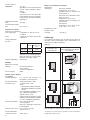
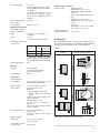
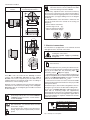
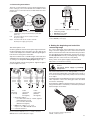
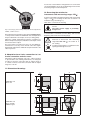
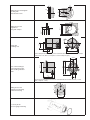
Betriebsanleitung
Messumformer für Drehwinkel KINAX WT 710
Mode d’emploi
Convertisseur de mesure
pour angle de rotation KINAX WT 710
Operating Instructions
Transmitter for angular position KINAX WT 710
WT 710 Bdfe
Camille Bauer AG
Aargauerstrasse 7
CH-5610 Wohlen/Switzerland
Telefon +41 56 618 21 11
Telefax +41 56 618 35 35
[email protected]
www.camillebauer.com
139 429-04
06.10
Betriebsanleitung
Messumformer für Drehwinkel
KINAX WT 710 .............................................................................. 3
Mode d’emploi
Convertisseur de mesure
pour angle de rotation KINAX WT 710 .........................................10
Operating Instructions
Transmitter for angular position
KINAX WT 710 ..............................................................................17
Sicherheitshinweise, die unbedingt beachtet werden müssen, sind in dieser Betriebsanleitung mit folgenden Symbolen markiert:
Les conseils de sécurité qui doivent impérativement être observés sont marqués des
symboles ci-contre dans le présent mode d’emploi:
Safety precautions to be strictly observed are marked with following symbols in the
Operating Instructions:
Der Anbau eines Zusatzgetriebes an den WT 710 muss im Herstellerwerk erfolgen!
L’adjonction d’un engrenage additionnel en WT 710 doit être faite en usine!
The mounting of an additional gear on the WT 710 must be made at the factory
Geräte dürfen nur fachgerecht entsorgt werden!
Les appareils ne peuvent être éliminés que de façon appropriée!
The instruments must only be disposed of in the correct way!
2
Betriebsanleitung
Messumformer für Drehwinkel KINAX WT 710
Inhaltsverzeichnis
1. Erst lesen, dann… ....................................................... 3
2. Kurzbeschreibung ........................................................ 3
3. Lieferumfang ................................................................ 3
4. Aufschlüsselung der Varianten .................................... 4
5. Technische Daten ........................................................ 4
6. Montage....................................................................... 5
3. Lieferumfang
Messumformer (Bild 1)
3 Spannklammern (Bild 4)
1 Schutzkappe
1 Betriebsanleitung (Bild 5), dreisprachig: Deutsch,
Französisch, Englisch
1 Ex-Bescheinigung (Bild 5), nur bei Geräten in
Ex-Ausführung
7. Elektrische Anschlüsse ................................................ 6
8. Anfangs- und Endwert
des Messbereiches einstellen ...................................... 7
9. Umstellung von 2-Drahtanschluss
in 3- bzw. 4-Drahtanschluss oder umgekehrt.............. 8
10. Drehrichtung umkehren
bei Geräten mit Messbereichen grösser 150 ° .......... 8
11. Mass-Skizzen .............................................................. 8
12. Konformitätserklärung ............................................... 24
1. Erst lesen, dann …
Der einwandfreie und gefahrlose Betrieb
setzt voraus, dass die Betriebsanleitung
gelesen und die in den Abschnitten
Bild 1
Messumformer zum Anbau an Messgeräte mit drehbarer
Zeigerwelle (Bild 2)
1 Zwischenflansch
1 Dichtungsring
1 Mitnehmergabel für ∅ 1,5 mm am Messgerät
1 Kupplungshebel für ∅ 2 mm am Messumformer
3 Spannklammern (Bild 4)
3 Zylinderschrauben M4 ×8
1 Schutzkappe
1 Betriebsanleitung (Bild 5), dreisprachig: Deutsch,
Französisch, Englisch
1 Ex-Bescheinigung (Bild 5), nur bei Geräten
in Ex-Ausführung
6. Montage
7. Elektrische Anschlüsse
8. Anfangs- und Endwert
des Messbereiches einstellen
10. Drehrichtung umkehren bei Geräten
mit Messbereichen grösser 150
enthaltenen Sicherheitshinweise beachtet werden.
Der Umgang mit diesem Gerät sollte nur durch entsprechend geschultes Personal erfolgen, das das Gerät kennt
und berechtigt ist, Arbeiten in regeltechnischen Anlagen
auszuführen.
Das Gerät darf nur zum Anschliessen der elektrischen
Leitungen (Abschnitt 7) und zum Einstellen wie in Abschnitt
8 bis 10 beschrieben, geöffnet werden.
Bild 2
Messumformer mit Zusatzgetriebe (Bild 3)
3 Spannklammern (Bild 4)
1 Montagefuss
2 Sechskantschrauben M5 ×10
2 Federscheiben
1 Betriebsanleitung (Bild 5), dreisprachig: Deutsch,
Französisch, Englisch
1 Ex-Bescheinigung (Bild 5), nur bei Geräten
in Ex-Ausführung
Bei weitergehenden Eingriffen in das Gerät erlischt der
Garantieanspruch.
Bild 3
Betriebsanleitung
Messumformer für Drehwinkel KINAX WT 710
Mode d’emploi
convertisseur de mesure
pour angle de rotation KINAX WT 710
Operating manual
Transmitter for angular position
KINAX WT 710
2. Kurzbeschreibung
Der Messumformer KINAX WT 710 erfasst kontaktlos die Winkelstellung einer Welle und formt sie in einen eingeprägten,
dem Messwert proportionalen Gleichstrom um.
Ausführungen in Zündschutzart «Eigensicherheit» mit
eigensicherem Messausgang ergänzen die Baureihe des
Messumformers.
WT 710 B d-f-e
139 429-2
07.06
Camille Bauer AG
Aargauerstrasse 7
CH-5610 Wohlen/Switzerland
Telefon +41 57 21 21 11
Telefax +41 57 22 74 32
Telex 827 901 cbm ch
Bild 4
Bild 5
3
4. Aufschlüsselung der Varianten
5. Technische Daten
Erklärung der Bestell-Ziffern 1. bis 5.
Messeingang
Messbereiche:
BestellCode
Beschreibung
1.
Ausführung des Messumformers
1
Ex ia IIC T6,
Messausgang eigensicher
2
ATEX
Sonstige Ausführungen
2.
3.
9
Drehrichtung
Kalibriert für Drehrichtung Uhrzeigersinn
1
Kalibriert für Drehrichtung
Gegenuhrzeigersinn
2
Für V-Kennlinie
3
Kalibriert für Drehrichtung beidseitig und
markiert
4
0 … 10
°
1
0 … 30
°
2
0 … 60
°
3
0 … 90
°
4
0 … 180
°
5
6
°
Nichtnorm 0 … ≥ 5 bis 0 … < 270
V-Kennlinie [±
°
°] nach Auftrag
Messausgang
Ausgangsgrösse IA:
Eingeprägter Gleichstrom,
proportional zum Drehwinkel
Normbereiche:
0…1 mA,
3- oder 4-Drahtanschluss
0…5 mA,
3- oder 4-Drahtanschluss
0…10 mA,
3- oder 4-Drahtanschluss
4…20 mA, 2-Drahtanschluss
oder
0…20 mA, 3- oder 4-Drahtanschluss
durch Potentiometer einstellbar
4…20 mA,
3- oder 4-Drahtanschluss
0…20 mA, 4-Drahtanschluss
Nicht-Normbereiche:
0…> 1,00 bis 0…< 20 mA
3- oder 4-Drahtanschluss
9
A
Aussenwiderstand
(Bürde):
Ausgangssignal (Messausgang)
0 … 1 mA / 3- oder 4-Drahtanschluss
5.
0…≥ 10 ° bis 0…48 Umdr.
(mit Zusatzgetriebe)
Messbereich (Messeingang)
0 … 270
4.
Vorzugsbereiche
0…10, 0…30, 0…60, 0…90,
0…180 oder 0…270 °
710-
Standard, Messausgang nicht eigensicher
0…≥ 5 bis 0… ≤ 270 °
(ohne Getriebe)
Rext max. [kΩ] =
12 V
IA [mA]
(bei Geräten mit
DC/AC-Hilfsenergie
durch Allstrom-Netzteil,
mit Galvanischer Trennung)
A
0 … 5 mA / 3- oder 4-Drahtanschluss
B
0 … 10 mA / 3- oder 4-Drahtanschluss
C
4 … 20 mA / 2-Drahtanschluss oder
0 … 20 mA / 3- oder 4-Drahtanschluss
D
Rext max. [kΩ] =
4 … 20 mA / 3- oder 4-Drahtanschluss
E
(bei Geräten mit DC-Hilfsenergie,
ohne Galvanische Trennung)
0 … 20 mA / 4-Drahtanschluss
F
IA = Ausgangssignal-Endwert
Nichtnorm / 3- oder 4-Drahtanschluss
0 … > 1,00 bis 0 … < 20 mA
Z
H [V] –12 V
IA [mA]
Genauigkeitsangaben
Hilfsenergie
24 … 60 V DC/AC,
mit galvanischer Trennung
1
85 … 230 V DC/AC,
mit galvanischer Trennung
2
12 … 33 V DC,
ohne galvanische Trennung
A
12 … 30 V DC (Ex),
ohne galvanische Trennung
B
Bezugswert:
Messbereich
Grundgenauigkeit:
Fehlergrenze ≤ 0,5% für Bereiche
0…≤ 150 °
Fehlergrenze ≤ 1,5% für Bereiche
von 0…> 150 bis 0…270 °
Hilfsenergie H
Gleich- und
Wechselspannung:
Nennspannungen und ToleranzAngaben siehe «Tabelle 1»
Tabelle 1:
Nennspannungen UN
Toleranz-Angaben
24 … 60 V DC/AC
DC – 15 … + 33%
AC ± 15%
85 … 230 V DC/AC
Anmerkung:
Die noch weiter festgelegten Bestell-Ziffern befassen sich mit
Besonderheiten, u.a. mit dem Zusatzgetriebe zur Erweiterung
der Messbereiche.
4
(möglich nur bei der
Standard-Ausführung, Nicht Ex,
mit Galvanischer Trennung,
mit Allstrom-Netzteil
(DC und 45…400 Hz)
Nur Gleichspannung1: 12…33 V
(möglich bei der Standard-Ausführung, Nicht Ex, ohne Galvanische
Trennung)
Umgebungsbedingungen
Klimatische
Beanspruchung:
12…30 V
(erforderlich bei der Ex-Ausführung,
Zündschutzart Eigensicherheit
Ex ia IIC T6, ohne Galvanische
Trennung)
Ausführung mit erhöhter Klimafestigkeit
Temperatur – 40 bis + 70 °C
Rel. Feuchte im Jahresmittel
≤ 95%
10% p.p.
Max. Stromaufnahme: Ca. 5 mA + IA
Ex-Ausführung
Temperatur – 40 bis + 60 °C bei T6
bzw. – 40 bis + 75 °C bei T5
Mechanische Belastbarkeit
Vibrationsbeständigkeit
(ohne Zusatzgetriebe): 5 g je 2 h in 3 Richtungen
f ≤ 200 Hz
3 ×50 g je 10 Stösse
in 3 Richtungen
Zulässige statische
Belastung der Welle:
6. Montage
radial max.
16 N
83 N
axial max.
25 N
130 N
Tabelle 2:
Bei Rüttelbetrieb wird zur Erhöhung der Lebensdauer der Lager
weitgehende Entlastung der Welle
empfohlen
3,2
Beliebig
… unmittelbarer Befestigung
Werkstoff
Feldgehäuse:
Alu-Guss
Oberfläche eloxiert
Deckel aus Kunststoff
Stopfbuchsen:
Metall
Vorschriften
500 Veff, 50 Hz, 1 Min.
alle elektrischen Anschlüsse
gegen Gehäuse
(bei DC-Hilfsenergie, ohne
Galvanische Trennung)
Stossspannungsfestigkeit:
Zul. Gleichtaktspannung:
1 kV, 1,2/50 μs, 0,5 Ws
IEC 255-4, Kl. II
Ø90
IP 43 nach EN 60 529
ohne Getriebe
IP 64 mit Getriebe oder anderem
ebenbürtigem Anbau
°
M4
12
0
2,2 kVeff, 50 Hz, 1 Min.
zwischen…
… Hilfsenergie und Gehäuse
… Hilfsenergie und Messausgang
(bei DC/AC-Hilfsenergie, mit
Galvanischer Trennung)
±0,2
Nach EN 60 079-11: 2007
Prüfspannung:
Ø75-H7
Eigensicher:
Gehäuseschutzart:
M3
Die Normen EN 50 081-2 und
EN 50 082-2 werden eingehalten
… Befestigung mit Spannklammern
Elektromagnetische
Verträglichkeit:
5
90
Gebrauchslage:
Bohr-Ausschnitts-Pläne für
Anbauteil (am Messobjekt)
bei …
MessumformerAusführungen
0°
6 mm bzw.
1/4ʺ
12
2 mm
60 ±0,2
Richtung
Die Montagearten – genaugenommen – die zugehörigen BohrAusschnitts-Pläne und ihre Zuordnung zu den MessumformerAusführungen sind Inhalt der Tabelle 2.
15 +0,018
0
Antriebswellen ∅
75-H7
Schock:
Transport- und
Lagerungs-Temperatur: – 40 bis 80 °C
±0,2
Max. Restwelligkeit:
Standard-Ausführung
Temperatur – 25 bis + 70 °C
Rel. Feuchte im Jahresmittel
≤ 90% oder
Fortsetzung Tabelle 2 siehe nächste Seite!
1
100 V, 50 Hz
Gegen Falschpolung geschützt. Der niedrigste Spannungswert
darf 12 V nicht unterschreiten.
5
Fortsetzung der Tabelle 2:
Beim Festziehen und Ausrichten ist darauf zu
achten, dass die Lage des Messumformer-Nullpunktes und die Nullstellung des Messobjektes
übereinstimmen.
Bohr-Ausschnitts-Pläne für
Anbauteil (am Messobjekt)
bei …
30°
Um ein eventuell notwendiges Verschieben des elektrischen Nullpunktes auf die Nullstellung des Messobjektes
zu ermöglichen, wird empfohlen, auch die 3 Durchgangslöcher (3,2 mm Ø) für die «unmittelbare» Befestigung
(siehe oberer Bohr-Ausschnitts-Plan in «Tabelle 2») als
Langlöcher auszuführen.
Der elektrische Nullpunkt des Gerätes ist auf der Stirnseite der Welle und aussen auf dem Gehäuse markiert,
siehe Abbildungen:
– links für Drehwinkel-Messumformer
mit Bereichen 0 bis … °,
– rechts für Winkeltransmitter
mit V-Kennlinien-Bereichen.
Ø6,8
80
±0,2
95
80
52
44-H8
7. Elektrische Anschlüsse
113
Zum Anschliessen der elektrischen Leitungen ist der Messumformer mit Schraubklemmen und 2 Stopfbuchsen ausgerüstet.
61
Unbedingt sicher stellen, dass die Leitungen
beim Anschliessen spannungsfrei sind!
25
Möglicherweise drohende Gefahr,
230 V Netzspannung als Hilfsenergie
0°
M4
12
… Anbau an Messgeräte mit drehbarer Zeigerwelle
… Befestigung mit Montagefuss
MessumformerAusführungen
Ferner ist zu beachten, …
53 ±0,05
Die «unmittelbare» Befestigung verlangt 3 Schrauben M3,
wohingegen die «mit Fuss» 2 Schrauben M6 mit Muttern
erfordern. Die Schrauben gehören nicht zum Lieferumfang,
da ihre Längen durch die von Fall zu Fall schwankende Dicke
des Anbauteils am Messobjekt bestimmt werden.
Anbauteil (am Messobjekt) mit Ausschnitt und/oder Durchgangslöchern nach dem zutreffenden Bohr-AusschnittsPlan «Tabelle 2» versehen. Danach den Messumformer
montieren.
Bei der Festlegung des Montageortes (Messortes)
ist zu berücksichtigen, dass die Angaben unter
«Umgebungsbedingungen», Abschnitt «5. Technische Daten», eingehalten werden.
Bei Ex-Geräten ist beim Errichten und Warten
darauf zu achten, dass keine elektrostatische
Aufladung entsteht.
Der Messumformer darf nur zum Erfassen eines
Drehwinkels und nicht zur permanenten Drehzahlerfassung benutzt werden.
… dass die Daten, die zur Lösung der Messaufgabe
erforderlich sind, mit denen auf dem Typenschild (Bild 6)
des KINAX WT 710 übereinstimmen (Messeingang,
Messausgang,
Hilfsenergie)!
… dass der Gesamtwiderstand in der Messausgangsleitung (in Serie geschaltete Empfangsgeräte plus Leitung) den maximalen Aussenwiderstand Rext. max. nicht
überschreitet! Rext. max. siehe «Messausgang», Abschnitt
«5. Technische Daten»!
… dass bei der Verlegung der Messausgangsleitung
verdrillte Kabel verwendet werden und diese möglichst
getrennt von Starkstromleitungen zu verlegen sind!
Im übrigen landesübliche Vorschriften (z.B. für Deutschland VDE 0100 «Bedingungen über das Errichten von
Starkstromanlagen mit Nennspannungen unter 1000 Volt»)
bei der Installation und Auswahl des Materials der elektrischen Leitungen befolgen!
Bei Geräten in der Zündschutzart «Eigensicherheit» mit
eigensicherem Messausgang sind zusätzlich die Angaben
der Baumusterprüfbescheinigung, die EN 60 079-14,
sowie die nationalen Vorschriften für die Errichtung von
elektrischen Anlagen in explosionsgefährdeten Bereichen
zu berücksichtigen!
1.5
!
0.5
Typ WT710-216A B1AC EF// P
12 -30 V
0 -270°
0 – 1 mA
Manufactured: 1999
No. 710/710710/001/001
camille bauer AG, CH-5610 Wohlen, Switzerland
Bild 6. Beispiel eines Typenschildes.
6
7.1 Leitungen anschliessen
Im Gehäuse (1) befinden sich 4 Schraubklemmen (2.1) und
1 Erdungsanschluss (2.2). Die Schraubklemmen eignen sich
für max. 1,5 mm2 Drahtquerschnitte und sind nach Abnehmen
des Deckels zugänglich.
21
43
+
–
–
+
(1)
ZERO
SPAN
ZERO
(2.2)
S1
SPAN
+
S1
Rext
–
(2.1)
(2.2)
+
–
~ ~
A
(2)
H
4-Drahtanschluss (diverse mA-Signale)
A = Messausgang
H = DC/AC-Hilfsenergie
Rext = Aussenwiderstand
Bild 7. Gehäuse (1), Deckel abgenommen, mit Klemmen (2.1)
sowie Erdungsanschluss (2.2) und Stopfbuchsen (2).
Links: Gerät ohne Galvanische Trennung und mit
DC-Hilfsenergie.
Bild 9. Anschlussplan für 4-Drahtanschluss, mit Galvanischer
Trennung, DC/AC-Hilfsenergie.
Rechts: Gerät mit Galvanischer Trennung und mit
DC/AC-Hilfsenergie (Schaltnetzteil).
8. Anfangs- und Endwert
des Messbereiches einstellen
Kunststoff-Deckel abnehmen.
Stopfbuchs-Verschraubungen lösen und zusammen mit
den Quetschringen und Dichtungen aus den StopfbuchsÖffnungen herausnehmen. Diese Verschraubungsteile auf
die Leitungen auffädeln, und die Leitungsenden durch die
Stopfbuchs-Öffnungen ins Gehäuse stecken und durchziehen.
Sodann die Leitungsenden auf passende Länge abisolieren
und nach dem jeweils zutreffenden Anschlussplan (Bild 8
oder 9) an den Klemmen (2.1) und Erdungsanschluss (2.2)
anschliessen.
Danach die Verschraubungsteile in den Stopfbuchs-Öffnungen festziehen, und den Deckel wieder anbringen.
Die «grobe» Einstellung des Messbereich-Anfangswertes,
die darin besteht, die Nullstellung des Messobjektes auf den
äusserlich markierten Nullpunkt des Messumformers auszurichten, wurde bereits unter «6. Montage» beschrieben. In
diesem Abschnitt wird dagegen die genaue Einstellung, der
Feinabgleich, sowohl des Anfangswertes (Nullpunkt/ZERO)
als auch des Endwertes (Spanne/SPAN) behandelt.
Messumformer in Betrieb nehmen. Dazu einfach die Hilfsenergie einschalten.
Deckel vom Gehäuse abnehmen.
Achtung! Die Schraubklemmen (2.1) Bild 7
führen Strom.
Möglicherweise drohende Gefahr,
230 V Netzspannung als Hilfsenergie
+
–
Nun das Messobjekt in Nullstellung bringen, d.h. in die Position, in der der KINAX WT 710 den Ausgangsstrom 0 mA
(bei einem 3- oder 4-Drahtanschluss) bzw. 4 mA (bei dem
2-Drahtanschluss) ausgeben soll.
21
–
+
21
+
–
43
43
43
21
+
+
–
Brücke
Weicht der Ausgangsstrom mehr als 2% von seinem Anfangswert ab, dann zunächst die «grobe» Nullpunkteinstellung,
siehe Abschnitt «6. Montage», wiederholen.
–
Rext
Rext
Rext
+
–
–
+
–
A und H
Danach Potentiometer «ZERO» (Bild 10 bzw. Bild 11) mit
einem Uhrmacher-Schraubenzieher (Ø 2,3 mm) so drehen,
dass genau der gewünschte Ausgangsstrom fliesst.
+
+
–
A
+
H
+
A
–
H
2-Drahtanschluss 3-Drahtanschluss 4-Drahtanschluss
(4…20 mA)
(diverse
(diverse
mA-Signale)
mA-Signale)
A
H
Rext
= Messausgang …
… als 2-Drahtanschluss (4…20 mA, Signal im
Mess-Speise-Kreis)
… als 3- oder 4-Drahtanschluss (diverse
mA-Signale)
= DC-Hilfsenergie H = 12…33 V
bzw. H = 12…30 V bei Ex-Ausführung
= Aussenwiderstand
Bild 8. Anschlusspläne für 2-, 3- oder 4-Drahtanschluss, ohne
Galvanische Trennung, DC-Hilfsenergie.
(1)
ZERO
SPAN
S1
Bild 10. Gehäuse (1) mit den Einstell-Elementen
«ZERO», «SPAN» und «S1».
7
Bei einem allfälligen Wechsel im Anschliessen des Gerätes
(siehe Anschlusspläne in Bild 8) müssen jedoch Anfangs- und
Endwert des Messbereiches neu eingestellt werden.
10. Drehrichtung umkehren
bei Geräten mit Messbereichen
grösser 150 °
(1)
ZERO
SPAN
Winkeltransmitter mit Messbereichen > 150 ° haben für die
Drehrichtungsumkehr einen Schalter, der mit S1 bezeichnet
ist (Bild 10 und Bild 11).
S1
Deckel vom Gehäuse abnehmen.
Achtung! die Schraubklemmen (2.1) Bild 7
führen Strom.
Bild 11. Gehäuse (1), Ausführung mit Schaltnetzteil, mit den
Einstell-Elementen «ZERO», «SPAN» und «S1».
Möglicherweise drohende Gefahr,
230 V Netzspannung als Hilfsenergie
Sodann Messobjekt in Endlage drehen, d.h. in die Stellung, in
der der KINAX WT 710 den ihm zugedachten AusgangsstromEndwert, siehe Typenschild, haben soll.
Sodann den Schalter mit dem Uhrmacher-Schraubenzieher
(Ø 2,3 mm) mit einer Vierteldrehung umschalten und Anfangsund Endwert des Messbereiches neu einstellen.
Potentiometer «SPAN» mit dem erwähnten Schraubenzieher
derart drehen, dass genau der gewünschte AusgangsstromEndwert abgegeben wird.
Danach wieder eine Kontrolle des Nullpunktes vornehmen und
allenfalls mit dem ZERO-Potentiometer korrigieren. Danach
nochmal den Endwert prüfen. Beide Justiervorgänge solange
wiederholen bis Nullpunkt und Endwert genau stimmen.
S1
Achtung! Bei Geräten mit Messbereichen
kleiner 150 ° ist der Schalter S1 nicht
vorhanden.
Bei Einführung eines Uhrmacher-Schraubenziehers wird die Leiterplatte beschädigt.
9. Umstellung von 2-Drahtanschluss
in 3- bzw. 4-Drahtanschluss oder umgekehrt
Messumformer mit dem Bestell-Code 710 – ...D (siehe Abschnitt «4. Aufschlüsselung der Varianten») sind sowohl für
den 2-Drahtanschluss mit dem Ausgangsstrom 4…20 mA
als auch für den 3- bzw. 4-Drahtanschluss mit dem Ausgangsstrom 0…20 mA geeignet.
11. Mass-Skizzen
80
61
101
Ø2-h5
KINAX WT 710
Grundgerät
Ø75-f8
6
10,7
3
47
25
63,1
80
61
101
Ø6-h5
KINAX WT 710
Grundgerät
mit Zusatzgetriebe
Ø75-f8
15
21,5
3
94
110,1
8
25
5
3,2
12
0°
60 ±0,2
15 +0,018
0
M3
Bohr-Ausschnittsplan für
Befestigung mit
Zylinderschrauben
±0,2
Befestigung
mit Montagefuss
75-H7
50
30°
Ø90
Ø75-H7
90 ±0,2
Bohr-Ausschnittsplan für
Befestigung mit
Spannklammern
12
0°
M4
Ø6,8
80 ±0,2
50
95
37
(Falls bei dieser Montageart die Stopfbuchse im Weg sein sollte, ist der KINAX WT 710 um
120° zu drehen, vorher sind die drei Rundmuttern am Getriebe zu lösen).
61
113
Grundgerät zum Anbau
an Messgeräte mit
drehbarer Zeigerwelle
Ø80
52
44-H8
67
25
83,1
Das Messgerät muss mit rückseitig verlängerter Zeigerwelle (Durchmesser 1,5 mm, Länge
6…7 mm) ausgeführt werden.
12
0°
M4
Bohr-Ausschnittsplan für
Messgeräte-Gehäuse
53 ±0,05
Anbausatz für
Manometer
9
Mode d’emploi
Convertisseur de mesure pour angle de rotation KINAX WT 710
3. Etendue de la livraison
Sommaire
1. A lire en premier, ensuite… ........................................ 10
2. Description brève....................................................... 10
3. Etendue de la livraison............................................... 10
4. Codage des variantes ................................................ 11
5. Caractéristiques techniques ...................................... 11
Convertisseur de mesure (Fig. 1)
3 brides (Fig. 4)
1 capuchon protecteur
1 mode d’emploi (Fig. 5) en trois langues: allemand,
français, anglais
1 attestation Ex (Fig. 5), seulement pour Ex-versions
6. Montage .................................................................... 12
7. Raccordements électriques ....................................... 13
8. Ajustage des valeurs de début et de fin
de l’étendue de mesure ............................................. 14
9. Passage du raccordement à 2 fils
à 3 ou 4 fils ou vice versa .......................................... 15
10. Inversion du sens de rotation pour des
appareils avec étendues de mesure > 150
° ......... 15
11. Croquis d’encombrements ........................................ 15
12. Certificat de conformité ............................................. 24
1. A lire en premier, ensuite …
Pour un fonctionnement sûr et sans danger, il
est essentiel de lire le présent mode d’emploi
et de respecter les recommandations de
sécurité mentionnées dans les rubriques
Ffig. 1
Convertisseur de mesure pour montage à l’arrière
d’appareils de mesure (Fig. 2)
1 flasque annulaire
1 joint torique
1 fourchette d’entraînement pour ∅ 1,5 mm à fixer
à l’appareil de mesure
1 levier d’accouplement pour ∅ 2 mm à fixer au
convertisseur de mesure
3 brides (Fig. 4)
3 vis cylindrique M4 ×8
1 capuchon protecteur
1 mode d’emploi (Fig. 5) en trois langues: allemand,
français, anglais
1 attestation Ex (Fig. 5), seulement pour Ex-versions
6. Montage
7. Raccordements électriques
8. Ajustage des valeurs de début et de
fin de l’étendue de mesure
10. Inversion du sens de rotation pour des
appareils avec étendues de mesure
> 150
Ces appareils devraient uniquement être manipulés par
des personnes qui les connaissent et qui sont autorisées
à travailler sur des installations techniques du réglage.
L’appareil ne doit être ouvert que pour le raccordement des
lignes électriques (chapitre 7) et pour l’ajustage, comme
décrit au chapitre 8 à 10.
Fig. 2
Convertisseur de mesure avec engrenage additionnel
(Fig. 3)
3 brides (Fig. 4)
1 pied de montage
2 vis hexagonale M5 ×10
2 rondelles ressorts
1 mode d’emploi (Fig. 5)en trois langues: allemand,
français, anglais
1 attestation Ex (Fig. 5), seulement pour Ex-versions
En cas d’intervention plus poussée, la garantie d’usine
s’éteint.
Fig. 3
Betriebsanleitung
Messumformer für Drehwinkel KINAX WT 710
Mode d’emploi
convertisseur de mesure
pour angle de rotation KINAX WT 710
Operating manual
Transmitter for angular position
KINAX WT 710
2. Description brève
Le convertisseur de mesure KINAX WT 710 est destiné à la
conversion, sans contact, de la position angulaire d’un axe
en un courant continu proportionnel à cet angle.
La gamme livrable du convertisseur est complétée par une
version en mode de protection à «sécurité intrinsèque»
avec sortie de mesure à sécurité intrinsèque..
10
WT 710 B d-f-e
Camille Bauer AG
Aargauerstrasse 7
CH-5610 Wohlen/Switzerland
Telefon +41 57 21 21 11
Telefax +41 57 22 74 32
Telex 827 901 cbm ch
Fig. 4
Fig. 5
139 429-2
07.06
4. Codage des variantes
5. Caractéristiques techniques
Explication des chiffres de commande 1. à 5.
Entrée de mesure
Etendues de mesure:
Code
de cde.
Description
1.
2.
3.
710-
Standard, sortie de mesure pas à
sécurité intrinsèque
1
Etendues préférentielles
0…10, 0…30, 0…60, 0…90,
0…180 ou 0…270 °
Ex ia IIC T6,
ATEX
Sortie de mesure à sécurité intrinsèque
2
0…≥ 10 ° à 0…48 tours
(avec engrenage)
Autres exécutions
9
Sens de rotation
Etalonné pour sens horaire
1
Etalonné pour sens antihoraire
2
Pour caractéristique en V
3
Etalonné pour deux sens de rotation et
marqué
4
Sortie de mesure
Sortie IA:
Courant continu,
proportionnel à l’angle de rotation
Valeurs nominales:
0…1 mA,
raccordement à 3 ou 4 fils
0…5 mA,
raccordement à 3 ou 4 fils
0…10 mA,
raccordement à 3 ou 4 fils
Etendue de mesure
(entrée de mesure)
0 … 10
°
1
0 … 30
°
2
0 … 60
°
3
0 … 90
°
4
0 … 180
°
5
0 … 270
°
6
Caractéristique V [±
°
°] selon ordre
4…20 mA, raccordement à 2 fils
ou
0…20 mA, raccordement à 3 ou 4
fils, ajustable avec potentiomètre
4…20 mA,
raccordement à 3 ou 4 fils
0…20 mA, raccordement à 4 fils
Valeurs
non-normalisées:
0…> 1,00 à 0…< 20 mA
raccordement à 3 ou 4 fils
9
A
Résistance de charge: Rext max. [kΩ] =
A
0 … 5 mA / raccordement à 3 ou 4 fils
B
0 … 10 mA / raccordement à 3 ou 4 fils
C
4 … 20 mA / raccordement à 2 ou
0 … 20 mA / raccordement à 3 ou 4 fils
D
4 … 20 mA / raccordement à 3 ou 4 fils
E
0 … 20 mA / raccordement à 4 fils
F
Non-normalisé, raccordement à 3 ou 4 fils
0 … > 1,00 à 0 … < 20 mA
Z
12 V
IA [mA]
(pour appareils avec alimentation
auxiliaire CC/CA par bloc d’alimentation tous-courants,
avec séparation galvanique)
H [V] –12 V
Rext max. [kΩ] =
IA [mA]
Signal de sortie (sortie de mesure)
0 … 1 mA / raccordement à 3 ou 4 fils
5.
°
Exécution du conv. de mesure
Non-normalisée 0 … ≥ 5 à 0 … < 270
4.
0…≥ 5 à 0… ≤ 270
(sans engrenage)
(pour appareils avec alimentation
auxiliaire CC,
sans séparation galvanique)
IA = Valeur finale de la sortie du
signal
Indications concernant la précision
Alimentation auxiliaire
24 … 60 V CC/CA,
avec séparation galvanique
1
85 … 230 V CC/CA,
avec séparation galvanique
2
12 … 33 V CC,
sans séparation galvanique
A
12 … 30 V CC (Ex),
sans séparation galvanique
B
Valeur de référence:
Etendue de mesure
Précision de base:
Limite d’erreur ≤ 0,5% pour étendues
0…≤ 150 °
Limite d’erreur ≤ 1,5% pour étendues
entre 0…> 150 à 0…270 °
Alimentation auxiliaire H
Tension continue et
tension alternative:
Tensions nominales et tolérances
voir «Tableau 1»
Tableau 1:
Tensions nominales UN
Tolérances
24 … 60 V CC/CA
CC – 15 … + 33%
CA ± 15%
85 … 230 V CC/CA
Remarque
Les chiffres de codage supplémentaires concernent des
particularités comme p.ex. les engrenages additionnels pour
étendre les gammes des étendues de mesure.
(seulement possible avec
l’éxecution standard, non-Ex,
avec séparation galvanique,
avec bloc d’alimentation auxiliaire
(CC et 45…400 Hz)
11
Influence de l’ambiance extérieure
12…33 V
(possible avec l’exécution standard,
non-Ex, sans séparation galvanique)
Sollicitations
climatiques:
12…30 V
(nécessaire pour l’exécution Ex,
mode de protection à sécurité intrinsèque Ex ia IIC T6, sans séparation
galvanique)
Ondulation résiduelle
max.:
Exécution avec sollicitations climatiques accruées
Température – 40 à + 70 °C
Humidité relative en moyenne annuelle ≤ 95%
10% p.p.
Exécution Ex
Température – 40 à + 60 °C en T6
resp. – 40 à + 75 °C en T5
Consommation propre
max:
Env. 5 mA + IA
Capacité mécanique
Résistance aux vibrations
(sans engrenage):
5 g pendant 2 h dans les 3 axes
f ≤ 200 Hz
Chocs:
Exécution standard
Température – 25 à + 70 °C
Humidité relative en moyenne annuelle ≤ 90% ou
3 ×50 g, 10 chocs dans chacune des
3 directions
Charge admissible
sur l’axe:
∅ de l’arbre
2 mm
6 mm resp.
1/4ʺ
radial max.
16 N
83 N
axial max.
25 N
130 N
Température lors du
transport ou du
stockage:
– 40 à 80 °C
6. Montage
Ces méthodes de fixation resp. les plans de perçage et de
découpe et leur correspondance avec l’exécution du convertisseur font l’objet du tableau 2.
Tableau 2:
Exécutions des
convertisseurs
Plan de perçage et de découpe
pour le montage sur l’objet à
mesurer pour …
Lors de son utilisation avec des
vibrations il est conseillé pour prolonger la durée de vie des paliers,
que l’axe ne soit pas chargé
60 ±0,2
Quelconque
Matériau
Boîtier pour montage
extérieur:
Presse-étoupes:
En fonte d’aluminium
Surface éloxée
Couvercle en plastique
12
0°
… montage direct
Position d’utilisation:
3,2
15 +0,018
0
Tension continue
seulement1:
5
M3
Métal
Normes et prescriptions
Les normes EN 50 081-2 et
EN 50 082-2 sont respectées
Protection du boîtier:
IP 43 selon EN 60 529
sans engrenage
IP 64 avec engrenage ou autre dispositif similaire
0°
12
Résistance aux chocs: 1 kV, 1,2/50 μs, 0,5 Ws
CEI 255-4, Cl. II
Suite du tableau 2 voir à la page suivante!
Tension admissible
en mode commun:
1
12
100 V, 50 Hz
Ø75-H7
500 Veff, 50 Hz, 1 min.
toutes les bornes électriques contre
le boîtier (avec alimentation auxiliaire
CC, sans séparation galvanique)
±0,2
2,2 kVeff, 50 Hz, 1 min.
entre…
… alimentation auxiliaire et boîtier
… alimentation auxiliaire et sortie de
mesure
(avec alimentation auxiliaire CC/CA,
avec séparation galvanique)
Ø90
Tension d’essai:
M4
75-H7
Selon EN 60 079-11: 2007
90 ±0,2
Sécurité intrinsèque:
… montage à l’arrière d’instr. de mesure
Compatibilité
électromagnétique:
Protection en cas d’inversion de polarité. La tension minimale ne
doit pas être inférieure à 12 V.
Suite du tableau 2:
Plan de perçage et de découpe
pour le montage sur
l’objet à mesurer pour …
Afin de permettre un ajustage éventuel du point zéro électrique par rapport à la position zéro de l’objet à mesurer,
il est conseillé de réaliser les 3 perçages (3,2 mm Ø) pour
montage «direct» (voir plan de perçage et de découpe
«tableau 2») sous forme de trous allongés.
Le point zéro électrique de l’appareil est marqué sur
la face avant de l’axe et à l’extérieur du boîtier comme
suit:
– à gauche pour des convertisseurs angulaires
avec des étendues 0 à … °,
30°
… Fixation par pied de montage
Exécutions des
convertisseurs
Lors de l’ajustage et du serrage il faut faire attention que le point zéro électrique du convertisseur et la position zéro de l’objet à mesurer
correspondent.
Ø6,8
80
±0,2
95
– à droite pour des convertisseurs angulaires
avec des étendues à caractéristique en V.
80
52
7. Raccordements électriques
113
Le convertisseur de mesure comporte des bornes et
2 presse-étoupes pour le raccordement des câbles électriques.
61
Lors du raccordement des câbles, se rassurer
impérativement que toutes les lignes soient
hors tension!
25
Danger imminent de 230 V alimentation
auxiliaire
0°
M4
12
… Montage à l’arrière d’instruments de mesure
44-H8
Veiller en plus, …
53 ±0,05
Le «montage direct» nécessite 3 vis M3. Pour la fixation
«avec pied» il faut utiliser 2 vis et écrous M6. Ces vis ne
font pas partie de la livraison, ceci du fait que leur longueur
varie selon l’épaisseur du support.
Réaliser sur l’objet à mesurer la découpe et/ou les perçages
nécessaires selon le plan de perçage et de découpe correspondant selon «Tableau 2» et monter le convertisseur
de mesure.
Pour la détermination de l’endroit de montage
(endroit de mesure) il faut respecter les indications de la rubrique «Influence de l’ambiance
extérieure» du chapitre «5. Caractéristiques
techniques».
Lors du montage ou de l’entretien d’appareils
en sécurité intrinsèque, veuillez s.v.p. prendre
toutes les précautions nécessaires pour éviter
toutes charges électrostatiques.
Le convertisseur de mesure est destiné exclusivement au captage d’un angle de rotation, il ne
doit pas servir à la mesure permanente d’une
vitesse de rotation.
… que les caractéristiques techniques qui permettent de
résoudre le problème de mesure correspondent aux données mentionnées sur la plaquette signalétique (Fig. 6) du
sortie de mesure,
KINAX WT 710 (entrée de mesure,
alimentation auxiliaire)!
… que la résistance totale du circuit de sortie de mesure (instruments récepteurs connectés en série plus
résistance des lignes) n’excède pas la valeur maximum
Rext. mentionnée sous «Sortie de mesure» du chapitre
«5. Caractéristiques techniques»!
… d’utiliser pour le circuit de sortie de mesure des câbles
avec fils torsadés par paire et de les passer si possible
séparément des lignes courant-fort!
Au reste, respecter les prescriptions nationales pour
l’installation et le choix du matériel des conducteurs
électriques!
Pour les appareils en mode de protection «à sécurité
intrinsèque» avec sortie de mesure à sécurité intrinsèque il faut respecter les indications contenues dans
le certificat d’essai du modèle type, l’EN 60 79-14,
ainsi que les prescriptions nationales pour la réalisation
d’installations électriques dans des enceintes avec danger
d’explosions!
1.5
!
0.5
Typ WT710-216A B1AC EF// P
12 -30 V
0 -270°
0 – 1 mA
Manufactured: 1999
No. 710/710710/001/001
camille bauer AG, CH-5610 Wohlen, Switzerland
Fig. 6. Exemple d’une plaquette signalétique.
13
7.1 Raccorder les lignes
Le boîtier (1) comporte 4 bornes à vis (2.1) et 1 prise de
terre (2.2). Ces bornes à vis sont prévues pour une section
des fils de max. 1,5 mm2, elles deviennent accessibles en
enlevant le couvercle.
21
43
+
–
–
+
(1)
ZERO
SPAN
ZERO
(2.2)
S1
SPAN
+
S1
Rext
–
(2.1)
(2.2)
+
–
~ ~
A
(2)
Raccordement à 4 fils (différents signaux mA)
Fig. 7. Boîtier (1) couvercle enlevé, avec bornes (2.1) ainsi que
prise de terre (2.2) et presse-étoupes (2).
à gauche: Appareil sans séparation galvanique et avec alimentation
auxiliaire CC.
à droite:
H
Appareil avec séparation galvanique et avec alimentation
auxiliaire CC/CA (bloc d’alimentation).
A = Sortie de mesure
H = Alimentation auxiliaire DC/AC
Rext = Résistance extérieure
Fig. 9. Schéma de connexion pour raccordement à 4 fils, avec
séparation galvanique, alimentation auxiliaire CC/CA.
8. Ajustage des valeurs de début et de fin de
l’étendue de mesure
Enlever le couvercle en matière plastique.
Dévisser les raccords des presse-étoupes et les sortir ensemble avec les rondelles de serrage et les joints de la partie
fixe des presse-étoupes. Enfiler ces pièces sur les câbles et
introduire les câbles dans la partie arrière du convertisseur
à travers les trous des presse-étoupes.
Dénuder les fils sur une longueur suffisante et les raccorder
aux bornes (2.1) et à la prise de terre (2.2) selon le schéma
de connexion correspondant (Fig. 8 ou 9).
Ensuite remettre en place les pièces des raccords et les
serrer correctement.
L’ajustage «grossier» du début de l’étendue de mesure
consistant à faire correspondre le point zéro de l’objet
à mesurer avec le repère du point zéro marqué sur le
convertisseur de mesure déjà été décrit dans le chapitre
«6. Montage». Le présent chapitre est donc consacré à
l’ajustage précis et fin aussi bien de la valeur de début
(point zéro/ZERO) que de la valeur de fin (plage/Span) de
l’étendue de mesure.
Mettre en service le convertisseur en enclenchant simplement
l’alimentation auxiliaire.
Enlever le couvercle du boîtier.
Attention! Les bornes à vis (2.1) Fig. 7 sont
sous tension.
Danger imminent de 230 V alimentation
auxiliaire!
–
+
Ramener l’objet à mesurer dans sa position zéro, c.à.d.
dans la position dans laquelle le KINAX WT 710 doit fournir
un courant de sortie de 0 mA (pour le raccordement à 3 ou
4 fils) resp. de 4 mA (pour le raccordement à 2 fils).
21
–
+
21
+
–
43
43
43
21
+
+
–
Pont
Si le courant de sortie dévie de plus de 2% de la valeur de
début, refaire encore une fois l’ajustage «grossier» du point
zéro décrit dans le chapitre «6. Montage».
–
–
A et H
Raccordement
à 2 fils
(4…20 mA)
Rext
–
–
+
H
Rext
Rext
+
A
+
+
Rext
–
A
+
H
+
A
–
H
Raccordement
Raccordement
à 3 fils (différents à 4 fils (différents
signaux mA)
signaux mA)
= Sortie de mesure …
… raccordement à 2 fils (4…20 mA, signal du
circuit de mesure)
… raccordement à 3 ou 4 fils (différents
signaux mA)
= Alimentation auxiliaire CC H = 12…33 V
resp. H = 12…30 V en exécution Ex
= Résistance extérieure
Fig. 8. Schéma de connexion pour raccordement à 2, 3 ou 4 fils,
sans séparation galvanique, alimentation auxiliaire CC.
14
Ensuite tourner à l’aide d’un tournevis horloger (Ø 2,3 mm)
le potentiomètre «ZERO» (Fig. 10 resp. Fig. 11) pour obtenir
la valeur désirée précise du courant de sortie.
(1)
ZERO
SPAN
S1
Fig. 10. Boîtier (1) avec les éléments d’ajustage
«ZERO», «SPAN» et «S1».
Toutefois, en cas de modification du type de raccordement
(voir schémas de connexion de la Fig. 8) les valeurs de début et de fin d’étendue de mesure ont besoin d’un nouvel
ajustage.
(1)
ZERO
10. Inversion du sens de rotation pour des
appareils avec étendues de mesure 150 °
SPAN
Les convertisseurs angulaires avec une étendue de mesure
> 150 ° comportent pour l’inversion du sens de rotation
un commutateur marqué S1 (Fig. 10 et Fig. 11).
S1
Enlever le couvercle du boîtier.
Attention! Les bornes à vis (2.1) Fig. 7 sont
sous tension.
Fig. 11. Boîtier (1), exécution avec bloc d’alimentation, avec les
éléments d’ajustage «ZERO», «SPAN» et «S1».
Danger imminent de 230 V alimentation
auxiliaire!
Ensuite amener l’objet à mesurer dans la position finale,
c.à.d. dans la position dans laquelle le KINAX WT 710 doit
fournir le courant de sortie final correspondant à la valeur
indiquée sur la plaquette signalétique.
Tourner ensuite le commutateur d’un quart de tour à l’aide
d’un tournevis horloger (Ø 2,3 mm) et régler de nouveau la
valeur de début et de fin d’étendue de mesure.
Tourner à l’aide du tournevis déjà mentionné le potentiomètre
«SPAN» pour obtenir exactement la valeur finale désirée du
courant de sortie.
Ensuite revérifier le point zéro et le cas échéant le corriger à
l’aide du potentiomètre «ZERO». Contrôler encore une fois la
valeur finale. Répèter ces deux opérations d’ajustage jusqu’à
ce que les points zéro et de fin d’étendue correspondent
exactement.
S1
Attention! Les appareils avec valeur finale de
l’étendue de mesure plus faible que 150 °
ne possèdent pas le commutateur S1.
Le circuit imprimé peut être endommagé si
on introduit un tournevis.
9. Passage du raccordement à 2 fils à 3 ou 4
fils ou vice versa
Les convertisseurs de mesure avec le code de commande
710 – ...D (voir chapitre «4. Codage des variantes») sont prévus
aussi bien pour le raccordement à 2 fils avec un courant de
sortie de 4…20 mA que pour le raccordement à 3 resp à 4
fils avec un courant de sortie de 0…20 mA.
11. Croquis d’encombrements
80
61
101
Ø2-h5
KINAX WT 710
Appareil de base
Ø75-f8
6
10,7
3
47
25
63,1
80
61
101
Ø6-h5
KINAX WT 710
Appareil de base
avec engrenage additionnel
Ø75-f8
15
21,5
3
94
110,1
25
15
5
3,2
12
0°
60 ±0,2
15 +0,018
0
M3
Plan de perçage et de découpe pour
fixation par vis à tête cylindrique
Fixation
par pied de montage
75-H7
50
30°
Ø75-H7
Ø90
±0,2
90
±0,2
Plan de perçage et de découpe pour
fixation par brides
12
0°
M4
Ø6,8
80 ±0,2
50
95
37
(Au cas où lors de ce montage un des presse-étoupe générait, il faut tourner le
KINAX WT 710 de 120°, après avoir dévissé les 3 écrous de fixation du réducteur).
61
113
Appareil de base
pour montage à l’arrière
d’instruments de mesure
Ø80
52
44-H8
67
25
83,1
L’appareil de mesure doit être fabriqué avec un axe d’aiguille prolongé (diamètre 1,5 mm,
longueur 6…7 mm).
12
0°
M4
Plan de perçage et de
découpe pour le boîtier
de l’appareil de mesure
53 ±0,05
Jeu de pièces pour
montage sur manomètre
16
Operating Instructions
Transmitter for angular position KINAX WT 710
3. Scope of supply
Contents
1. Read first and then… ................................................. 17
2. Brief description......................................................... 17
3. Scope of supply ......................................................... 17
4. Specification and ordering information...................... 18
5. Technical data ............................................................ 18
Transmitter (Fig.1)
3 clamps (Fig. 4)
1 protection cap
1 operating instructions (Fig. 5), in three languages:
German, French, English
1 Ex approval (Fig. 5), for instruments in Ex version only
6. Mounting .................................................................... 19
7. Electrical connections................................................ 20
8. Setting the beginning and end
of the measuring range .............................................. 21
9. Adaptation from 2-wire connection to
3 or 4-wire connection and vice versa....................... 22
10. Reversing the rotation
for instruments with measuring ranges 150
° ....... 22
11. Dimensional drawings................................................ 22
12. Declaration of conformity .......................................... 24
1. Read first and then …
The proper and safe operation of the device
assumes that the Operating Instructions are
read carefully and the safety warnings given
in the various Sections
Fig. 1
Transmitter for fitting on measuring instruments with
revolving indicator shaft (Fig. 2)
1 mounting ring
1 sealing ring
1 driving fork for 1.5 mm dia. on measuring instrument
1 coupling lever for 2 mm dia. on angle transmitter
3 clamps (Fig. 4)
3 screws M4 ×8
1 protection cap
1 operating instructions (Fig. 5), in three languages:
German, French, English
1 Ex approval (Fig. 5), for instruments in Ex version only
6. Mounting
7. Electrical connections
8. Setting the beginning and end
of the measuring range
10. Reversing the rotation for instruments
with measuring ranges 150
are observed.
The device should only be handled by appropriately trained
personnel who are familiar with it and authorised to work
in electrical installations.
The instrument must only be opened to make the electrical
connections (section 7) and for setting, as described in
section 8 to 10.
Fig. 2
Transmitter with additional gear (Fig. 3)
3 clamps (Fig. 4)
1 mounting foot
2 screws M5 ×10
2 spring washer
1 operating instructions (Fig. 5), in three languages,
German, French, English
1 Ex approval (Fig. 5), for instruments in Ex version only
The guarantee is no longer valid if the instrument is further
tampered with.
Fig. 3
Betriebsanleitung
Messumformer für Drehwinkel KINAX WT 710
Mode d’emploi
convertisseur de mesure
pour angle de rotation KINAX WT 710
Operating manual
Transmitter for angular position
KINAX WT 710
2. Brief description
The KINAX WT 710 converts the angular position of a shaft
into a load-independent direct current signal, proportional
to the angular position.
Explosion-proof “Intrinsically safe” versions with I.S. measuring output rounds off this series of transmitters.
WT 710 B d-f-e
139 429-2
07.06
Camille Bauer AG
Aargauerstrasse 7
CH-5610 Wohlen/Switzerland
Telefon +41 57 21 21 11
Telefax +41 57 22 74 32
Telex 827 901 cbm ch
Fig. 4
Fig. 5
17
4. Specification and ordering information
5. Technical data
Significance of digits 1. to 5.
Measuring input
OrderCode
Description
1.
2.
3.
°
710-
Standard, measuring output
non-intrinsically safe
1
Preferred ranges
0…10, 0…30, 0…60, 0…90,
0…180 or 0…270 °
Ex ia IIC T6,
ATEX
Measuring output intrinsically safe
2
0…≥ 10 ° to 0…48 turns
(with additional gear)
Other versions
9
Sense of rotation
Calibrated for sense of rotation clockwise
1
Calibrated for sense of rotation counterclockwise
2
For “V” characteristic
3
Both senses of rotation, calibrated and
marked
4
Measuring output
Output variable IA:
Load-independent DC current,
proportional to the input angle
Standard ranges:
0…1 mA,
3 or 4-wire connection
0…5 mA,
3 or 4-wire connection
0…10 mA,
3 or 4-wire connection
Measuring range (measuring input)
4…20 mA, 2-wire connection
or
0…20 mA, 3 or 4-wire connection
adjustable with potentiometer
0 … 10
°
1
0 … 30
°
2
0 … 60
°
3
0 … 90
°
4
4…20 mA,
3 or 4-wire connection
0 … 180
°
5
0…20 mA, 4-wire connection
0 … 270
°
6
“V” characteristic [±
5.
0…≥ 5 to 0… ≤ 270
(without gear)
Version of the transmitter
Non-standard 0 … ≥ 5 to 0 … < 270
4.
Measuring ranges:
°] to order
°
Non-standard ranges: 0…> 1.00 to 0…< 20 mA
3 or 4-wire connection
9
A
External resistance:
Rext max. [kΩ] =
12 V
IA [mA]
(for instruments with
DC/AC power supply
by AC/DC power pack,
with electric isolation)
Output signal (measuring output)
0 … 1 mA / 3 or 4-wire connection
A
0 … 5 mA / 3 or 4-wire connection
B
0 … 10 mA / 3 or 4-wire connection
C
4 … 20 mA / 2-wire connection or
0 … 20 mA / 3 or 4-wire connection
D
4 … 20 mA / 3 or 4-wire connection
E
(for DC power supply,
without electric isolation)
0 … 20 mA / 4-wire connection
F
IA = Output signal end value
Non-standard / 3 or 4-wire connection
0 … > 1.00 to 0 … < 20 mA
Z
Power supply
Rext max. [kΩ] =
H [V] –12 V
IA [mA]
Accuracy
Reference value:
Measuring range
Basic accuracy:
Limit of error ≤ 0.5% for ranges
0…≤ 150 °
Limit of error ≤ 1.5% for ranges from
0…> 150 to 0…270 °
24 … 60 V DC/AC,
with electric isolation
1
85 … 230 V DC/AC,
with electric isolation
2
12 … 33 V DC,
without electric isolation
A
Power supply H
12 … 30 V DC (Ex),
without electric isolation
B
DC and
AC voltage:
Nominal voltages and tolerances
see “Table 1”
Table 1:
Nominal voltages UN
Tolerances
24 … 60 V DC/AC
DC – 15 … + 33%
AC ± 15%
85 … 230 V DC/AC
Note
The remaining order code digits concern special features, e.g.
the ancillary gear for extending the measuring ranges.
18
(only possible with
standard version, non-Ex,
with electric isolation,
with AC/DC power pack
(DC and 45…400 Hz)
12…33 V
(possible with standard version,
non-Ex, without electric isolation)
Environmental conditions
Climatic rating:
12…30 V
(necessary with Ex version, type
of protection “Intrinsic safety”
Ex ia IIC T6, without electric
isolation)
Max. residual ripple:
10% p.p.
Max. current
consumption:
Approx. 5 mA + IA
version with improved climatic rating
Temperature – 40 to + 70 °C
Annual mean relative humidity
≤ 95%
Ex version
Temperature – 40 to + 60 °C at T6
resp. – 40 to + 75 °C at T5
Mechanical withstand
Permissible vibration
(without additional
gear):
Shock:
Standard version
Temperature – 25 to + 70 °C
Annual mean relative humidity
≤ 90% or
5 g every 2 h in 3 directions
f ≤ 200 Hz
3 ×50 g
10 shocks each in 3 directions
Permissible static load
on the shaft:
Drive shafts dia.
Sense
2 mm
6 mm resp.
1/4ʺ
radial max.
16 N
83 N
axial max.
25 N
130 N
Transportation and
storage temperature:
– 40 to 80 °C
6. Mounting
The relationship between the types of mounting, or more
precisely the corresponding cut-out diagrams and the different
versions of the transmitter can be seen from Table 2.
Table 2:
Transmitter
versions
Drilling and cut-out diagrams
for mounting transmitters …
3.2
Any
12
0°
Mounting position:
60 ±0.2
If subjected to vibration the shaft
load should be as low as possible to
ensure optimum life of the bearing
15 +0.018
0
DC voltage only1:
Housing:
Cable glands:
… directly
Material
Cast aluminium
Corrosion resistant finish
Plastic protection cap
5
Metal
M3
Regulations
The standards EN 50 081-2 and
EN 50 082-2 are observed
Impulse voltage
withstand:
±0.2
IP 43 acc. to EN 60 529
without gear
IP 64 with gear or other similar
mounting
Ø90
Housing protection:
Ø75-H7
500 Veff, 50 Hz, 1 min.
all electrical connections to
housing
(with DC power supply, without
electric isolation)
12
0°
M4
90
2,2 kVeff, 50 Hz, 1 min.
between…
… power supply and housing
… power supply and measuring
output
(with DC, AC power supply, with
electric isolation)
75-H7
Acc. to EN 60 079-11: 2007
Test voltage:
±0.2
Intrinsic safety:
… with clamps
Electromagnetic
compatibility:
Continuation of table 2 see on next page!
1 kV, 1,2/50 μs, 0.5 Ws
IEC 255-4, Cl. II
Permissible commonmode voltage:
100 V, 50 Hz
1
Polarity reversal protection. The voltage must not fall below 12 V.
19
Continuation of table 2:
Pay attention when aligning and tightening the
transmitter that the electrical zero and the zero
of the item being measured coincide.
Drilling and cut-out diagrams
for mounting transmitters…
To permit any adjustment of the electrical zero that may
be necessary to match the zero of the measured object,
we recommend also elongating the three 3.2 mm diameter
mounting holes (see upper drilling and cut-out diagram
in Table 2).
The electrical zero of the transmitter is marked on the
end of the shaft and on the outside of the casing (see
diagrams):
– left for rotation transmitters
with the range of 0 to … °,
Ø6.8
80
±0.2
95
80
– right for rotation transmitters
with V characteristic ranges.
52
44-H8
113
7. Electrical connections
The transmitter is equipped with screw terminals and two
cable glands for the electrical connections.
61
Make sure that the cables are not live when
making the connections!
25
The 230 V power supply is potentially
dangerous
0°
M4
12
… fitting to meas. instruments with revolving indicator shaftr
… with mounting foot
30°
Transmitter
versions
Also note that, …
53 ±0.05
Three M3 screws are needed for the “directly” mounted
versions and two M6 nuts and bolts for those “with a
bracket”. The screws, respectively nuts and bolts are not
supplied, because the required length varies according to
the thickness of the mounting surface.
Make the cut-out or drill the holes in the item onto which the
transmitter is to be mounted according to the corresponding drilling and cut-out diagram given in Table 2 and then
fit the transmitter.
When deciding where to install the transmitter
(measuring location), take care that the ambient
conditions given in Section 5 “Technical data”
are not exceeded.
When installing or servicing intrinsically safe
(Ex) instruments, care must be taken to avoid
electrostatic charges.
The transmitter may only be use for detecting a
turning angle and not to permanently measure
speed.
… the data required to carry out the prescribed measurement must correspond to those marked on the nameplate
(Fig. 6) of the KINAX WT 710 (measuring input,
measuring output,
power supply)!
… the total loop resistance connected to the output (receiver plus leads) does not exceed the maximum permissible
value Rext! See “Measuring output” in Section 5. “Technical
data” for the maximum values of Rext. max.!
… twisted cores must be use for the measured variable
input and output leads and rouled as far away as possible
from power cables!
In all other respects, observe all local regulations when selecting the type of electrical cable and installing them!
In the case of “Intrinsically safe” explosion-proof versions with I.S. measuring output, the supplementary
information given on the EC-type-examination certificate,
the EN 6079-14 and also local regulations applicable to
electrical installations in explosion hazard areas must be
taken into account!
1.5
!
0.5
Typ WT710-216A B1AC EF// P
12 - 30 V
0 -270°
0 – 1 mA
Manufactured: 1999
No. 710/710710/001/001
camille bauer AG, CH-5610 Wohlen, Switzerland
Fig. 6. Example of a nameplate.
20
7.1 Connecting transmitters
There are 4 screw terminals (2.1) and 1 ground terminal (2.2)
in the casing (1). The screw terminals are suitable for wire
gauges up to 1.5 mm2 and are accessible when the cover
is removed.
21
43
+
–
–
+
(1)
ZERO
SPAN
ZERO
SPAN
(2.2)
S1
+
S1
Rext
–
(2.1)
(2.2)
+
–
~ ~
A
(2)
4-wire connection (different mA-signals)
Fig. 7. Housing (1) with the cover removed showing the screw
terminals (2.1), the ground terminal (2.2) and cable
glands (2).
Left:
H
Instrument without electric isolation and with
DC power supply.
A = Measuring output
H = DC/AC power supply
Rext = External resistance
Fig. 9. Connection diagram for 4-wire connection, with electric
isolation, DC/AC power supply.
Right: Instrument with electric isolation and with
DC/AC power supply (power pack).
8. Setting the beginning and end of the
measuring range
Take off the plastic cover.
Undo the gland nut and remove the pinch ring and seal from
the gland opening. Place these parts over the cable in the
correct order and pass the end of the cable through the gland
hole into the housing of the transmitter.
Strip the insulation from a suitable length of the leads and
connect them to the terminals (2.1) and ground terminal (2.2)
according to the respecive wiring diagram (Fig.8 or 9).
Then fit the gland seal, pinch ring and nut. Tighten the gland
nut and replace the cover.
Firstly, switch on the power supply to the transmitter.
Take off the cover from the housing.
Caution! The screw terminals (2.1) Fig. 7
are live.
The 230 V power supply is potentially
dangereous
–
+
21
–
+
21
–
43
43
43
21
+
+
–
Bridge
+
The coarse adjustment of the beginning of the measuring
range consists in aligning the zero of the measured device
with the external zero mark on the transmitter. The procedure
was described in Section 6 “Mounting”. This Section concerns
the fine adjustment not only of the beginning of the range
(ZERO), but also of the end of the scale (SPAN).
Place themeasured device at its zero position, i.e. the position at which the KINAX WT 710 should produce 0 mA (3
or 4-wire connection), respectively 4 mA (2-wire connection)
at its output.
Should the output current differ by more than 2% from its initial
value, repeat the coarse zero setting procedure described
in Section 6 “Mounting”.
–
–
A and H
H
Rext
–
–
+
A
Rext
Rext
+
2-wire
connection
(4…20 mA)
+
+
Rext
–
A
3-wire
connection
(different
mA-signals)
+
H
+
A
–
Then adjust the “ZERO” potentiometer (Fig. 10 resp. Fig. 11)
using a watchmaker’s screwdriver (2.3 mm diam.) so that the
desired output current flows.
H
4-wire
connection
(different
mA-signals)
= Measuring output …
… as 2-wire connection (4…20 mA, signal in
output/powering circuit)
… as 3 or 4-wire connection
(different mA-signals)
= DC power supply H = 12…33 V
resp. H = 12…30 V with Ex version
= External resistance
Fig. 8. Connection diagrams for 2, 3 or 4-wire connection,
without electric isolation, DC power supply.
(1)
ZERO
SPAN
S1
Fig. 10. Housing (1) with the adjustments
“ZERO”, “SPAN” and “S1”.
21
If, however, a transmitter be changed from one to the other
(see wiring diagrams in Fig. 8), the beginning and end of the
measuring range must be readjusted.
10. Reversing the rotation for
instruments with measuring ranges 150
(1)
ZERO
°
SPAN
A switch is provided on angular transmitters with a measuring
range > 150 ° for reversing the direction of rotation. It is
marked S1 (Fig. 10 and Fig. 11).
S1
Take off the cover from the housing.
Caution! The screw terminals (2.1) Fig. 7
are live.
The 230 V power supply is potentially
dangereous!
Fig. 11. Housing (1), version with power pack, with the adjustments
“ZERO”, “SPAN” and “S1”.
Now rotate the measured device to its opposite limit position,
i.e. the position at which the KINAX WT 710 should produce
the prescribed full-scale output current (see rating plate).
Then operate the switch by turning it a quarter of a turn with
a watchmakers screwdriver (2.3 mm diam.) and reset the
beginning and end of the measuring range.
Adjust the “SPAN” potentiometer with the screwdriver as
before until precisely the prescribed full-scale output current
is measured at the output.
S1
The recheck the zero point and correct on the ZERO potentiometer if necessary. Check the full-scale value again.
Repeat both adjustments until both zero point and full-scale
value are precise.
Attention! In instruments with measuring
° the switch S1 is
range less than 150
not existing.
Forching a watchmaker’s screwdriver into the
opening will damage the PCB.
9. Adaptation from 2-wire connection to 3 or
4-wire connection and vice versa
Transmitters with the ordering code 710 – ...D (see Section
4 “Specification and ordering information”) are designed
for either a two-wire connection with an output range of
4…20 mA or a three or four-wire connection with an output
range of 0…20 mA.
11. Dimensional drawings
80
61
101
Ø2-h5
KINAX WT 710
Basic unit
Ø75-f8
6
10.7
3
47
25
63.1
80
61
101
Ø6-h5
KINAX WT 710
Basic unit with
additional gear
Ø75-f8
15
21.5
3
94
110.1
22
25
5
3.2
12
0°
60 ±0,2
15 +0,018
0
M3
Drilling and cut-out diagram
for fixing with
cheesehead screws
±0,2
Fixing with
mounting foot
75-H7
50
30°
Ø90
Ø75-H7
90 ±0,2
Drilling and cut-out
diagram for
fixing with clamps
12
0°
M4
Ø6.8
80 ±0.2
50
95
37
(If the cable glands are in the way when mounted as above, the KINAX WT 710 should be
rotated over 120°, after loosening the 3 screws holding the gear).
61
113
Basic unit for fitting to
measuring instruments
with revolving indicator
shaft
Ø80
52
44-H8
67
25
83.1
The measuring instrument must have an extended indicator shaft at the back (1.5 mm
diam., length 6…7 mm).
12
0°
M4
Drilling and cut-out
diagram for measuring
instrument housing
53 ±0.05
Accessory kit for
pressure gauge mounting
23
12. Konformitätserklärung / Certificat de conformité / Declaration of conformity
EG - KONFORMITÄTSERKLÄRUNG
EC DECLARATION OF CONFORMITY
Dokument-Nr./
Document.No.:
Kinax WT 710_CE-konf.DOC
Hersteller/
Manufacturer:
Camille Bauer AG
Switzerland
Anschrift /
Address:
Aargauerstrasse 7
CH-5610 Wohlen
Produktbezeichnung/
Product name:
Elektronischer Messumformer für Drehw inkel, Anbaugerät
Electronic Transmitter for angular position
Typ / Type:
Kinax WT 710
Das bezeichnete Produkt stimmt mit den Vorschriften folgender Europäischer Richtlinien
überein, nachgewiesen durch die Einhaltung folgender Normen:
The above mentioned product has been manufactured according to the regulations of the following European directives proven through compliance with the following standards:
Nr. / No.
R i c h t l i n i e / D i r e c t i ve
2004/108/EG
2004/108/EC
Elektromagnetische Verträglichkeit - EMV-Richtlinie
Electromagnetic compatibility - EMC directive
EMV /
EMC
Fachgrundnorm /
Generic Standard
M e s s ve r f a h r e n /
Measurement methods
Störaussendung /
Emission
Störfestigkeit /
Immunity
EN 61000-6-4 : 2007
EN 55011 : 2007+A2:2007
EN 61000-6-2 : 2005
IEC
IEC
IEC
IEC
IEC
IEC
Nr. / No.
R i c h t l i n i e / D i r e c t i ve
2006/95/EG
E l e k t r i s c h e B e t r i e b s m i t t e l z u r V e r we n d u n g i n n e r h a l b b e s t i m m t e r S p a n n u n g s grenzen – Niederspannungsrichtlinie – CE-Kennzeichnung : 95
E l e c t r i c a l e q u i p m e n t f o r u s e wi t h i n c e r t a i n v o l t a g e l i m i t s – L o w V o l t a g e D i r e c tive – Attachment of CE marking : 95
2006/95/EC
61000-4-2: 1995+A1:1998+A2:2001
61000-4-3: 2006+A1:2007
61000-4-4: 2004
61000-4-5: 2005
61000-4-6: 2008
61000-4-11: 2004
EN/Norm/Standard IEC/Norm/Standard
EN 61010-1: 2001
IEC 61010-1: 2001
Die explosionsgeschützte Ausführung dieses Produkts stimmt mit der Europäischen
Richtlinie 94/9/EG überein.
The explosion protected variant of this product has been manufactured according the
European directive 94/9
Ort, Datum /
Place, date:
Wohlen, 12. August 2009
Unterschrift / signature:
24
M. Ulrich
J. Brem
Leiter Technik / Head of engineering
Qualitätsmanager / Quality manager