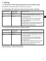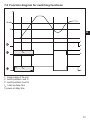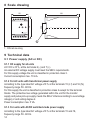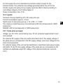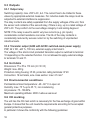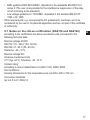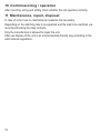
1
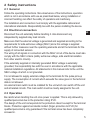
Operating instructions Standstill monitor A300 02 / 2011 7390337 / 01 UK Contents 1 Preliminary note���������������������������������������������������������������������������������������������������4 1.1 Symbols used������������������������������������������������������������������������������������������������4 1.2 Warning signs used���������������������������������������������������������������������������������������4 2 Safety instructions�����������������������������������������������������������������������������������������������5 2.1 General����������������������������������������������������������������������������������������������������������5 2.2 Electrical connection��������������������������������������������������������������������������������������5 2.3 Operation�������������������������������������������������������������������������������������������������������5 2.4 Housing temperature�������������������������������������������������������������������������������������6 2.5 Tampering with the device�����������������������������������������������������������������������������6 3 Function and features������������������������������������������������������������������������������������������6 4 Mounting��������������������������������������������������������������������������������������������������������������7 4.1 Mounting of the pulse pick-ups����������������������������������������������������������������������7 5 Electrical connection��������������������������������������������������������������������������������������������8 5.1 Terminal connection���������������������������������������������������������������������������������������8 5.2 Power supply�������������������������������������������������������������������������������������������������9 5.3 Connection of pulse pick-ups������������������������������������������������������������������������9 6 Controls and visual indication����������������������������������������������������������������������������10 7 Setting��������������������������������������������������������������������������������������������������������������� 11 7.1 Selection of the switching function and setting range���������������������������������� 11 7.1.1 Operating state: minimum rotational speed reached / standstill��������� 11 7.1.2 Fault state: below minimum rotational speed������������������������������������� 11 7.2 Setting of the switch point����������������������������������������������������������������������������12 7.3 Hysteresis����������������������������������������������������������������������������������������������������12 7.4 Start-up delay����������������������������������������������������������������������������������������������12 7.5 Function diagram for switching functions����������������������������������������������������13 8 Scale drawing����������������������������������������������������������������������������������������������������14 9 Technical data����������������������������������������������������������������������������������������������������14 9.1 Power supply (AC or DC)����������������������������������������������������������������������������14 9.1.1 DC supply for all units�������������������������������������������������������������������������14 9.1.2 For AC units with transformer power supply���������������������������������������14 9.1.3 For units with AC/DC switched-mode power supply���������������������������14 9.2 Inputs�����������������������������������������������������������������������������������������������������������15 2 9.2.1 Pulse pick-up supply���������������������������������������������������������������������������15 9.3 Outputs��������������������������������������������������������������������������������������������������������16 9.3.1 Output relay����������������������������������������������������������������������������������������16 9.3.2 Transistor output (A300 with AC/DC switched-mode power supply)��16 9.4 Unit data������������������������������������������������������������������������������������������������������16 9.5 Environmental conditions����������������������������������������������������������������������������16 9.6 CE marking��������������������������������������������������������������������������������������������������16 9.7 Notes on the cULus certification (DA0116 and DA0122)�����������������������������17 10 Commissioning / operation������������������������������������������������������������������������������18 11 Maintenance, repair, disposal��������������������������������������������������������������������������18 This document is the original instructions. 3 UK 1 Preliminary note The operating instructions apply to all control monitors of type A300. There are the following differences between the individual units: • Rating of the permissible AC or AC/DC supply which is indicated on the type label of the unit. • Setting range (pulses/min), indicated on the type label. • Additional transistor output, indicated on the wiring label. The operating instructions are part of the unit. They contain information about the correct handling of the product. Read them before use to get familiar with operating conditions, mounting and operation. Adhere to the safety instructions. The operating instructions are made for authorised persons according to the EMC and low voltage guidelines. 1.1 Symbols used ► Instruction Important note Non-compliance can result in malfunction or interference. Information Supplementary note. 1.2 Warning signs used WARNING Warning of serious personal injury. Death or serious irreversible injuries may result. CAUTION Warning of personal injury. Slight reversible injuries may result. NOTE Warning of damage to property. 4 2 Safety instructions 2.1 General Follow the operating instructions. Non-observance of the instructions, operation which is not in accordance with use as prescribed below, wrong installation or incorrect handling can affect the safety of operators and machinery. The installation and connection must comply with the applicable national and international standards. Responsibility lies with the person installing the device. 2.2 Electrical connection UK Disconnect the unit externally before handling it. Also disconnect any independently supplied relay load circuits. Make sure that the external voltage is generated and supplied according to the requirements for safe extra-low voltage (SELV) since this voltage is supplied without further measures near the operating elements and at the terminals for the supply of connected sensors. The wiring of all signals in connection with the SELV circuit of the device must also comply with the SELV criteria (safety extra-low voltage, safe electrical isolation from other electric circuits). If the externally supplied or internally generated SELV voltage is externally grounded, the responsibility lies with the user in accordance with the applicable national installation regulations. All statements in this manual refer to the unit the SELV voltage of which is not grounded. It is not allowed to supply external voltage to the terminals for the pulse pick-up supply. The consumption of current which exceeds the value given in the technical data is not allowed. An external main switch must be installed for the unit which can switch off the unit and all related circuits. This main switch must be clearly assigned to the unit. 2.3 Operation Be careful when handling the unit once power is applied. This is only allowed by qualified personnel due to the protection rating IP 20. The design of the unit corresponds to the protection class II except for the terminal blocks. Protection against accidental contact (finger protection to IP 20) for qualified personnel is only guaranteed if the terminal screw has been completely screwed in. 5 2.4 Housing temperature As described in the technical specifications below the device can be operated in a wide ambient temperature range. Because of the additional internal heating the operating elements and the housing walls can have high perceptible temperatures when touched in hot environments. 2.5 Tampering with the device In case of malfunction of the unit or queries please contact the manufacturer. Any tampering with the device can seriously affect the safety of operators and machinery. This is not permitted and leads to the exclusion of any liability and warranty claims. 3 Function and features The A300 is a pulse evaluation system for monitoring underspeed/standstill. It receives pulses from external sensors, measures the pulse interval and calculates the input frequency (= actual value), compares it with the preset switch point (preset value) and switches the output in accordance with the preset parameters. • Setting range: see type label (standard values: 5...25 and 20...100 pulses/min). • Maximum input frequency: as standard 15,000 pulses/min (which corresponds to 250 Hz). Special versions: DA0025 (4.5 kHz), DA0038 (1.6 kHz), DA0200 (200 Hz). If this value is exceeded, the A300 switches as for input frequency = 0. • Minimum pulse length: 2 ms. • Pulse pick-ups: 3-wire DC PNP, 2-wire AC/DC, 2-wire quadronorm, incremental encoders, mechanical switches. Signal level for the A300 pulse input: minimum 14 V. WARNUNG The device is not approved for safety-related tasks in the field of operator protection. 6 4 Mounting WARNUNG Mount the unit in a control cabinet with a protection rating of at least IP 54 to guarantee protection against accidental contact with voltages and against atmospheric influence. The control cabinet should be installed in accordance with local and national rules and regulations. ►► Mount the unit on a DIN rail or by means of a mounting base. Once mounted leave enough space between the unit and the top and bottom of the control cabinet (to enable air circulation and to avoid excessive heating). UK 4.1 Mounting of the pulse pick-ups ►► Adhere to the mounting instructions of the manufacturer. For optimum functioning of inductive switches the following dimensions should be adhered to: A B A A C A B=2xA C = ½ x Sn Mounting of the pulse pick-ups 7 5 Electrical connection WARNUNG The unit must only be connected by an electrician. The national and international regulations for the installation of electrical equipment must be observed. Avoid contact with voltages. Disconnect the plant from power before wiring. Check if the relays are connected to voltages of external power supplies. Observe the usual ESD protection measures. ►► In order to avoid malfunction caused by interference, lay the sensor cable separately from the load cable. Max. length of the sensor cable: 500 m. 5.1 Terminal connection A300 with switched-mode power supply 1: signal input 2: power supply DC 3: switching output 4: power supply 5: transistor output 8 A300 with transformer power supply 1: signal input 2: power supply DC 3: switching output 4: power supply 5.2 Power supply Power supply either • at terminals 15 and 16 (AC/DC; for A 300 with switched-mode power supply; AC for A300 with transformer power supply) • or at terminals 6 and 7 (24 V DC). For DC units the supply voltage must be protected externally. The terminals of the DC supply are directly linked with the terminals of the pulse pick-up supply. This is why the SELV criteria must be adhered to for DC supply (protective low voltage, circuit galvanically separated from other circuits, not UK earthed). If the DC circuit is to be earthed (e.g. because of national regulations), the PELV criteria have to be adhered to (protective low voltage, circuit galvanically separated from other circuits). If the unit is supplied with AC voltage, the low voltage supply for the pulse pick-up meets the SELV criteria. The device shall be supplied from an isolating source and protected by an overcurrent protection device such that the limited voltage circuit requirements in accordance with UL 508 are met. 5.3 Connection of pulse pick-ups 3-wire DC PNP 2-wire DC quadronorm BN BNBNBN WHWHWH WH 5 5 55 BK BK BKBK 4 4 44 BU BUBUBU3 3 3 3 2-wire AC/DC 5 5 55 BK BK BKBK4 4 44 BN BNBNBN 5 5 55 BU BUBUBU4 4 44 mechanical switch 5 5 55 4 4 44 BN = brown BK = black BU = blue WH = white A300 provides approx. 24V DC (max. 30 mA) for the supply of pulse pick-ups. Pulse pick-ups which need higher voltage/higher current consumption must have an external supply. In this case the reference point of the external voltage must be connected to terminal 6; the positive pole of the external power supply must not be connected with the A300. 9 Please also adhere to the SELV criteria for the pulse pick-up connection so that there is no dangerous contact voltage at the sensor which can enter the unit. 6 Controls and visual indication 1 2 3 4 5 6 7 8 switchpoint min 1 max pulse/min 2 3 4 5 power func. 9 I 10 11 12 13 14 II 15 16 A300 1: setting of the switch point (pulses/min.) 2: LED: lights when the output relay is energised 3: LED: indication of the input pulses 4: LED: operating voltage o.k. 5: selection of the switching function and setting range 10 III IV 7 Setting 7.1 Selection of the switching function and setting range ►► Selection is done with switch (5), there are 4 functions. 7.1.1 Operating state: minimum rotational speed reached / standstill Switch position I IV Setting range [pulses/min.] 5...25 20...100 Switching function The output relay energises when the input frequency (pulses/min) becomes lower than the UK set switch point (SP). If the input frequency becomes higher again, the relay switches back at the switch point + hysteresis (SP+Hy). The output relay is de-energised during the startup delay and as long as the input frequency is higher than the set switch point. 7.1.2 Fault state: below minimum rotational speed Switch position II III Setting range [pulses/min.] 5...25 20...100 Switching function The output relay de-energises when the input frequency (pulses/min) becomes lower than the set switch point (SP). If the input frequency becomes higher again, the relay switches back at the switch point + hysteresis (SP+Hy). The output relay is energised during the start-up delay and as long as the input frequency is higher than the set switch point. Relay energised = transistor output conductive Relay de-energised = transistor output blocked 11 7.2 Setting of the switch point ►► Set the switch point with pot (1). For low switch points the A300 recognises changes of the actual value only after a reaction time (which depends on the interval between two successive pulses). This particularly applies to the switching functions I and II. For these functions the reaction time is about 12 s in case of a switch point of 5 pulses/min and about 1.2 s in case of a switch point of 50 pulses/min. 7.3 Hysteresis The hysteresis determines the difference between switch-on point and switch-off point (switch-on point = the output changes its switching state, switch-off point = the output switches back to the previous state). The hysteresis is set to the factor 1.05 (which corresponds to 5 % of the switch point). With unequal distances between cams different times between two successive pulses are measured. They can be above or below the switch point so that the output continuously changes its switching state. By increasing the hysteresis factor this can be prevented. 7.4 Start-up delay The start-up delay suppresses an error signal as long as the machine is in the process of starting and has not yet reached its nominal speed. • It is set to 15 s but can be reduced by a resistor between the terminals 1 and 2. Resistor values: between 100 k (which corresponds to 2 s) and 3.9 M (which corresponds to 14 s). • After application of the operating voltage the start-up delay is active only once. If the drive is often turned on and off, couple the supply voltage of the drive and the monitor. By doing so, the start-up delay is active every time the drive is turned on. 12 7.5 Function diagram for switching functions f SP+Hy SP UK 1 0 tST 1 0 1) tST 1 0 1: power supply of the unit 2: switch positions I and IV 3: switch positions II and III tST = start-up delay time 1) power-on delay time 13 8 Scale drawing 110 55 75 35,5 1 2 3 4 5 6 7 8 9 10 11 12 13 14 15 16 1 1: DIN rail mounting 9 Technical data 9.1 Power supply (AC or DC) 9.1.1 DC supply for all units 24 V DC ±10 %, at the terminals 6 (-) and 7 (+). An external DC voltage supply must meet the SELV requirements. For this supply voltage the unit is classified in protection class 3. Current consumption max. 70 mA. 9.1.2 For AC units with transformer power supply According to the type label AC voltage ±10 % at the terminals 15 (L1) and 16 (N), frequency range 50...60 Hz. For this supply the unit is classified in protection class 2 except for the terminal blocks. The protective low voltage generated within the unit for the monitor supply and pulse pick-up supply meets the SELV criteria according to overvoltage category 2 and soiling degree 2. Power consumption max. 5 VA. 9.1.3 For units with AC/DC switched-mode power supply According to the type label AC voltage ±10 % at the terminals 15 and 16, frequency range 50...60 Hz. 14 For this supply the unit is classified in protection class 2 except for the terminal blocks. The protective low voltage generated within the unit for the monitor supply and pulse pick-up supply meets the SELV criteria according to overvoltage category 2 and soiling degree 2. Power consumption max. 5 VA. 9.2 Inputs Terminal 4 for pnp switching 24 V DC pulse pick-ups. Current consumption: approx. 10 mA. Switch point for pnp pulse pick-up: ≥ 14 V ON; < 7 V OFF The maximum input frequency to be detected is 250 Hz (corresponds to 15000 pulses/min) DA0200: 200 Hz (corresponds to 12000 pulses/min). UK 9.2.1 Pulse pick-up supply Voltage: typ. 24 V DC; current rating: max. 30 mA, protected against short circuit and overload. For external DC supply of the unit via the terminals 6 and 7 the supply voltage of the pulse pick-up corresponds to the DC supply voltage, less a low voltage for the short-circuit protection. For external supply of the unit via the transformer or switched-mode power supply (terminals 15 and 16) the supply voltage of the pulse pick-up corresponds to the rectified non-stabilised output DC voltage of the internal transformer (nominal 24 V). 15 9.3 Outputs 9.3.1 Output relay Switching capacity: max. 250 V AC, 4 A. The current has to be limited to these values by appropriate external measures. For inductive loads the relays must be subjected to external interference suppression. The relay contacts are safely separated from the supply voltages of the unit, from the sensor and contacts of the second relay, if there is any, up to a rated voltage of 250 V AC. They conform to the overvoltage category 2 and soiling degree 2. NOTE: If the relay is used to switch very low currents (e.g. plc inputs), considerable contact resistance can arise. The life of the relay contacts is considerably reduced by excess current or by the switching of unprotected inductive loads. 9.3.2 Transistor output (A300 with AC/DC switched-mode power supply) PNP, 24 V DC, ±20 %, 700 mA, external supply at terminal 9. The voltage of the short-circuit protected transistor output is switched to terminal 10 depending on the selected function. It is not allowed to apply external voltage to terminals 10 and 11. 9.4 Unit data Dimensions: 75 x 55 x 110 mm (H / W / D) Weight: max. 400 g Protection rating housing: IP 40, protection rating terminals: IP 20 Connection: 16 terminals, wire cross section: max: 2.5 mm² 9.5 Environmental conditions Permissible ambient temperature: -20...60 °C in open air Humidity: max. 75 % up to 35 °C, non condensing Air pressure: 75...106 KPa Maximum operating altitude: 2000 m above sea level 9.6 CE marking The unit has the CE mark which is necessary for the free exchange of good within Europe. It shows that the unit meets the requirements according to the accepted general protective purposes. In particular it shows the conformity with the following guidelines: 16 • EMC guideline EMC 89/336/EEC, stipulated in the standards EN 60947-5-2 annex X (The user is responsible for the interference suppression of the relay circuit according to the standard). • Low voltage guideline LV 73/23/EEC, stipulated in the standard EN 61010: 1993 + A2: 1995 Other requirements, e.g. concerning the EC guideline for machines, are to be considered by the user in his planned application and are not part of the certificate of conformity. 9.7 Notes on the cULus certification (DA0116 and DA0122) According to the certification the above-mentioned units correspond to the following technical data. Nominal voltage AC/DC: DA0116: 110...240 V (50...60 Hz) DA0122: 27...60 V (50...60 Hz) Tolerance: -20...10 % Nominal voltage DC: All above-mentioned units 27 V (typ. 24 V), Tolerance: -20...10 % Contact rating: According to cULus classification 6 A (250 V AC), B300, R300 Test conditions: Housing dimensions for the temperature-rise test 200 x 200 x 150 mm. Connection terminals: Up to 2.5 mm²; AWG 14 UK 17 10 Commissioning / operation After mounting, wiring and setting check whether the unit operates correctly. 11 Maintenance, repair, disposal In case of correct use no maintenance measures are necessary. Depending on the switching rate to be expected and the load to be switched, we recommend testing the relay contacts. Only the manufacturer is allowed to repair the unit. After use dispose of the unit in an environmentally friendly way according to the valid national regulations. 18