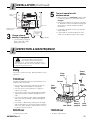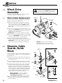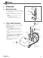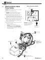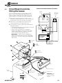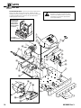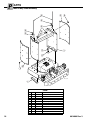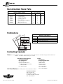
1
U
SER MANUAL
Boxcar Door Assist
Manual Number 6019803 R-3
cascade姞
corporation
Cascade is a Registered Trademark of Cascade Corporation
C
ONTENTS
Page
INTRODUCTION
Special Definitions
1
OPERATOR'S GUIDE
Safety Rules
1
Boxcar Door Assist
2
Industrial Lift Trucks
3
General Setup for Opening Doors
4
Picking Up, Securing Unit
4
Opening, Closing Doors
5
Open Docks
5
Close Quarters
6
Disengaging and Stowing
7
Troubleshooting
7
Safe Operation and Maintenance
8
OSHA Regulations
8
INSTALLATION
Truck Requirements
9
Electrical Installation
10
INSPECTION & MAINTENANCE
Daily
11
100-Hour Maintenance
11
500-Hour Maintenance
11
1000-Hour Maintenance
11
SERVICE
Winch Drive Assembly, Cable Replacement
12
Sheaves, Cable Guards, Guide Block
12
Electrical
13
PARTS
Product Identification
16
Base Unit
16
Multi-Clamp Tower Assembly
18
Narrow Doorway Boom/Sheave Assembly
19
Recommended Spare Parts
back cover
Publications
back cover
Contact Cascade
back cover
i
6019803 Rev. 3
I
NTRODUCTION
This User Manual is for the Cascade Boxcar Door Assist and
contains an Operator's Guide, Installation Instructions,
Inspection & Maintenance, Service and Parts. All specifications are shown in U.S. and (Metric) units where applicable.
Special Definitions
The statements shown appear throughout this Manual
where special emphasis is required. Read all WARNINGS
and CAUTIONS before proceeding with any work.
Statements labeled IMPORTANT and NOTE are provided
as additional information of special significance or to
make the job easier.
WARNING: Do not operate this unit with
an attachment unless you are a trained
and authorized lift truck driver.
WARNING – A statement preceded by
WARNING is information that should be
acted upon to prevent bodily injury. A
WARNING is always inside a ruled box.
CAUTION – A statement preceded by CAUTION is
information that should be acted upon to prevent
machine damage.
IMPORTANT – A statement preceded by IMPORTANT is
information that possesses special significance.
NOTE – A statement preceded by NOTE is information
that is handy to know and may make the job easier.
O
PERATOR'S GUIDE
This Section contains operating instructions for the
Cascade Boxcar Door Assist. It will help you avoid
common errors which can often cause damage to the
equipment or personnel injury.
This information is intended to simplify operator understanding about effective and safe Boxcar Door Assist
use and operation. Read this information thoroughly
before operating the unit. Be sure you know and
understand all operating procedures and safety precautions. If you have any questions, or don’t understand a
procedure, ask your supervisor.
Wireless
Remote
Control
Pickup Guides
Sliding
Boom,
Sheaves,
Winch
Cable
Guards
Emphasize Safety! Most accidents are caused by
operator carelessness or misjudgement. You must
watch for poorly maintained equipment and
hazardous situations and correct them.
Roll or Bale Clamp
Pad Grips
Power
Harness
Cable
Release
Internal
Battery (if
equipped)
Bumper
DA0013.ill
Cable & Hook
Frame with
Fork Slots
Front View - Fully Optioned Base Unit
6019803 Rev. 3
1
O
PERATOR'S GUIDE
Safety Rules – Boxcar Door Assist
Assure Door
Assist is centered
and secure prior
to lifting and
traveling.
Assure fork
safety locks
are engaged.
Assure carriage
is equipped
with fork stops.
DA0053.ill
DA0049.ill
Safety Chains, Hooks
Use gloves when
handling and
rigging cable.
Assure five (5) wraps
of cable minimum on
drum at all times.
Assure cable guards
are in place and
cable is covered.
DA0
Do not operate
winch with cover
removed.
Do not operate Door
Assist more than 2 ft.
(60 cm) above floor.
DA0055.ill
DA0050.ill
2 ft.
(60 cm)
Max.
Do not operate
Door Assist
when tilted.
CAUTION: Electrical interlocks prevent
unsafe operation with unit tilted, raised
too high, or overloaded. (Faults reset
automatically in 2-10 sec.)
DA0057.ill
2
6019803 Rev. 3
O
PERATOR'S GUIDE
Safety Rules – Industrial Lift Trucks
No riders
No reaching through mast
No standing under load
GA0172.ill
Tilt
With Load
Raise
3 in.
(8 cm)
No Load
P
P
Traveling
empty
Motor off, park, lower load
RAMPS
P
Watch clearances
No turning on ramp
No parking on ramp
GA0173.ill
TRAFFIC
STOP
Wet floors
6019803 Rev. 3
Bumps
Dips
Slow for
two-way traffic
Sound horn, slow
at intersection
Sound horn,
slow at corner
3
O
PERATOR'S GUIDE
General setup for opening boxcar doors
WARNING – Remain in truck or
stay clear of No Stand Zone when
opening or closing boxcar door.
Assure cable is rigged parallel to door and floor
– do not pull with cable at an angle. Cable
under tension is hazardous and may result in
equipment damage or bodily injury.
ON/OFF
IN
OUT
Boxcar Door
Assist Unit
Hook, Cable
Wireless
Remote
Control
NO STAND ZONE defined by door size,
movement range
Picking up, securing unit
1
Adjust forks to
slot width
OR
Position roll clamp pads
on towers ABOVE fork slots
DA0042.ill
RC1217.ill
2
DA0002.ill
OR
Short Arm
on RH side
Position bale clamp
pads on towers, pads
EVEN with bottom of unit
CL1958.ill
3
Pick up or clamp
unit and attach
safety chains
Connect
power
cable to
truck or
Internal
Battery
DA0023.ill
DA0018.ill
4
DA0019.ill
6019803 Rev. 3
O
PERATOR'S GUIDE
Opening, closing doors on open docks
1
A) Tilt mast
vertical
C) Position unit as
low as possible
2
A) Drive forward, touch
bumper just beyond door
open or close point.
2 ft. (60 cm)
Max.
DA0065.ill
B) Bale Clamp: Pads aligned with bottom of unit
B) Set parking brake,
truck in neutral.
C) Connect hook
to lowest
anchor point
on door
3
A) Release
winch
B) Manually
pull cable
from winch.
4
DA0021.ill
A) Engage winch, use IN
buttons on remote to pull
door partially open.
B) Assure no loose
or falling loads,
open door fully.
DA0022.ill
USING WIRELESS REMOTE
Winch Operating LED
OUT
• Operate winch by pressing both
IN buttons simultaneously.
• Use OUT button only to release
cable tension. Wait for motor to
stop before reversing direction.
• LED will blink when winch
operates. Replace Remote's
batteries if LED does not light.
Programming receiver for new
Remote: Assure Door Assist Unit
is level. Press and hold right-side
IN button until winch 'pulses' or
'jumps'. Test by pressing OUT.
IN
OUT
Press
END
BUTTON
IN
Press
BOTH
BUTTONS
DA0031.ill
6019803 Rev. 3
C) Press OUT button to
release tension, use IN
buttons to rewind cable.
DA0026.ill
WARNING: Do not continue pulling if
overload sensor deactivates winch. Check
for damaged door or load fouling door.
Reposition unit or cable connection point
on door before trying again.
5
O
PERATOR'S GUIDE
Opening, closing doors in close quarters
using narrow doorway boom
1
A) Tilt mast
vertical
2
C) Position unit as
low as possible
A) Drive forward,
allow clearance
for door to open.
2 ft. (60 cm)
Max.
DA0044.ill
B) Roll Clamp: Pads positioned above fork pockets
B) Set parking brake,
truck in neutral.
DA0059.ill
3
A) Release
winch
D) Manually pull cable
from winch, connect
hook to lowest anchor
point on door.
4
A) Engage winch, use IN
buttons on remote to pull
door partially open.
B) Assure no loose
or falling loads,
open door fully.
C) Insert locking
pin, thread
cable on unit.
B) Slide boom
for increased
pull range.
DA0040.ill
THREADING CABLE
C) Press OUT button to
release tension, use IN
buttons to rewind cable.
Loop
around
sheave,
under
cable
guard.
Pull cable through
guide, except when
boom is extended
6
DA0054.ill
DA0061.ill
WARNING: Do not continue pulling If
overload sensor deactivates winch. Check
for damaged door or load fouling door.
Reposition unit or cable connection point
on door before trying again.
6019803 Rev. 3
O
PERATOR'S GUIDE
Disengaging and Stowing
CAUTION – All cables and chains
must be disconnected and properly
stowed before disengaging unit from
truck. Follow the procedure shown:
2
1
3
Lower unit
to floor.
5
Disconnect and
stow power cable.
Disengage
unit.
DA0025.ill
4
Assure cable is
rewound with
hook stowed.
Disconnect and stow
safety chains or hooks.
DA0041.ill
T
ROUBLESHOOTING
5
Check fuse,
replace if
required
Check wireless
remote for
damage, battery
condition, replace
if required
2
NOTE: If cable runs in
wrong direction assure
that cable is spooling
from underside of drum.
+
Reprogram code
from remote (see
page 5)
4
Check power cable,
connectors,
replace worn or
damaged parts
3
Check Receiver LEDs:
NOTE: Fault conditions reset
automatically in 2-10 sec.
6019803 Rev. 3
1
Green:
Red:
Yellow:
Orange:
(all on):
Signal OK
Overload Fault
Tilt Fault
Height Fault
Overload sensor
installed backwards
DA0027.ill
7
S
AFE OPERATION AND MAINTENANCE
OSHA Regulations – Industrial Trucks and Attachments
(Specific Regulations from OSHA 1910.178 and 1917.17)
WARNING: The safe operation and maintenance of
industrial trucks is regulated by Occupational Safety
and Health (OSHA) regulations 1910.178 and
American National Standards Institute (ANSI) Safety Standard for
Powered Industrial Trucks, ANSI B56.1. When operating and
maintaining industrial trucks equipped with attachments you
should pay particular attention to the following sections of these
regulations. You should be familiar with all sections of these
regulations. Ask your employer for the complete regulations.
(a) General Requirement
(4) Modifications and additions which affect capacity and safe operation
shall not be performed by the customer or user without manufacturers prior written approval. Capacity, operation and maintenance
instruction plates, tags or decals shall be changed accordingly.
(5) If the truck is equipped with front-end attachments other than
factory installed attachments, the user shall request that the
truck be marked to identify the attachments and show the
appropriate weight of the truck and attachment combination at
maximum elevation with load laterally centered.
(6) The user shall see that all nameplates and markings are in place
and maintained in a legible condition.
(e) Safety Guards
(2) If the type of load presents a hazard, the user shall equip fork
trucks with a vertical load backrest extension in accordance with:
(a)(2) All new powered industrial trucks acquired and used by
an employer after February 15, 1972 shall meet the design and
construction requirements for powered industrial trucks
established in the “American National Standard for Powered
Industrial Trucks, Part II, ANSI B56.1”, except for vehicles
intended primarily for earth moving or over-the-road hauling.
(l) Operator Training
Only trained and authorized operators shall be permitted to operate
a powered industrial truck. Methods shall be devised to train
operators in the safe operation of powered industrial trucks.
(m) Truck Operations
(1) Trucks shall not be driven up to anyone standing in front of a
bench or other fixed object.
(2) No person shall be allowed to stand or pass under the elevated
portion of any truck, whether loaded or empty.
(3) Unauthorized personnel shall not be permitted to ride on
powered industrial trucks. A safe place to ride shall be provided
where riding of trucks is authorized.
(4) The employer shall prohibit arms or legs from being placed between
the uprights of the mast or outside the running lines of the truck.
(5i) When a powered industrial truck is left unattended, load
engaging means shall be fully lowered, controls shall be
neutralized, power shall be shut off and brakes set. Wheels shall
be blocked if the truck is parked on an incline.
(5ii) A powered industrial truck is unattended when the operator is 25
feet or more away from the vehicle which remains in his view, or
whenever the operator leaves the vehicle and it is not in his view.
(5iii) When the operator of an industrial truck is dismounted and
within 25 feet of the truck still in his view, the load engaging
means shall be fully lowered, controls neutralized and the
brakes set to prevent movement.
(6) A safe distance shall be maintained from the edge of ramps or
platforms while on any elevated dock or platform or freight car.
Trucks shall not be used for opening or closing freight doors.
8
(10) A load backrest extension shall be used whenever necessary to
minimize the possibility of the load or part of it from falling rearward.
(n) Traveling
(4) The driver shall be required to slow down and sound the horn at
cross isles and other locations where vision is obstructed. If the
load being carried obstructs forward view, the driver shall be
required to travel with the load trailing.
(7i) When ascending or descending grades in excess of 10 percent,
loaded trucks shall be driven with the load upgrade.
(7iii) On all grades the load and load engaging means shall be tilted back if
applicable, and raised only as far as necessary to clear the road surface.
(o) Loading
(1) Only stable or safely arranged loads shall be handled. Caution shall be
exercised when handling off-center loads which cannot be centered.
(2) Only loads within the rated capacity of the truck shall be handled.
(3) The long or high (including multiple-tiered) loads which may affect
capacity shall be adjusted.
(4) Trucks equipped with attachments shall be operated as partially
loaded trucks when not handling a load.
(5) A load engaging means shall be placed under the load as far as
possible; the mast shall be carefully tilted backward to stabilize the load.
(6) Extreme care shall be used when tilting the load forward or backward,
particularly when high tiering. Tilting forward with load engaging
means elevated shall be prohibited except to pick up
a load. An elevated load shall not be tilted forward except when the
load is in a deposit position over a rack or stack. When stacking or
tiering, only enough backward tilt to stabilize the load shall be used.
(p) Operation of the Truck
(1) If at any time a powered industrial truck is found to be in need of
repair, defective, or in any way unsafe, the truck shall be taken out
of service until it has been restored to safe operating condition.
(q) Maintenance of Industrial Trucks
(1) Any power-operated industrial truck not in safe operating
condition shall be removed from service. All repairs shall be
made by authorized personnel.
(5) All parts of any such industrial truck requiring replacement shall be
replaced only by parts equivalent as to safety with those used in the
original design.
(6) Industrial trucks shall not be altered so that the relative positions
of the various parts are different from what they were when originally
received from the manufacturer, nor shall they be altered either by the
addition of extra parts not provided by the manufacturer or by the
elimination of any parts. Additional counter-weighting of fork trucks
shall not be done unless approved by the truck manufacturer.
(7) Industrial trucks shall be examined before being placed in service
and shall not be placed in service if the examination shows any
condition adversely affecting the safety of the vehicle. Such examinations shall be made at least daily. When industrial trucks are used on
a round-the-clock basis, they shall be examined after each shift.
Defects when found shall be immediately reported and corrected.
Railroad Facilities (Ref. 1917.17)
(h) Before being opened fully, doors shall be opened slightly to ensure that
the load has not shifted during transit. Special precautions shall be
taken if the doors being opened are visibly damaged.
(i) If powered industrial trucks are used to open railcar doors, the trucks or
the railcar doors shall be equipped with door opening attachments.
Employees shall stand clear of the railcar doors while they are being
opened and closed.
(j) Only railcar door openers or powered industrial trucks equipped with
door opening attachments shall be used to open jammed doors.
6019803 Rev. 3
I
NSTALLATION
Truck Requirements
An IC lift truck with forks or clamp attachment is required to
pick up the electrically powered Boxcar Door Assist Unit.
WARNING – Lift truck must weigh 8000
lbs. (3630 Kg) minimum when using
Boxcar Door Assist. Use of lighter truck
not recommended.
Forks or Clamp Attachment
• Forks (2 x 5 x 48 in. L maximum)
• Paper Roll Clamp
• Bale Clamp
Forks
Bale Clamp
Paper Roll Clamp
DA0008.ill
Electrical Power
Truck-Powered Unit – Requires 12V @ 200A or 24V
@ 100A DC power from the truck battery or electrical
system. Use the No. 2-gauge twin cable and
connectors supplied with the unit (see Page 10 for
electrical cable installation).
Self-Powered Unit – Contains an internal 12V
battery and charger to supply all required power.
No truck power connection is required.
6019803 Rev. 3
9
I
NSTALLATION
Truck-Powered Unit (Steps 1, 2, 4, 5) – Use the No. 2-gauge twin
cable, fusebox and connectors supplied with the unit and install as
shown. Connect winch power cable to truck and test unit.
Self-Powered Unit (Steps 3, 4, 5) – Charge battery using 12V
charger supplied. Connect winch power cable to internal battery
as shown and test unit.
Inline Fusebox
(NOTE: located on
battery hold-down in
self-powered unit)
1
Determine location on truck
cowl for power connector
• Position connector for easy accessibility
and to avoid interference with truck or
mast components.
• Orient connector to avoid water and dirt
buildup if possible.
• Mount connector securely using hex
capscrews and nuts provided.
Fuse:
12V–200A
Hex Head
Mounting
Capscrews
+
2
Install power cables, fuseblock
to truck battery
• Route power cable directly to truck battery
terminals.
• Assure cables are connected correctly with
positive-to-positive and negative-tonegative. Use cable ties as necessary to
secure cable.
• Mount fuesbox solidly to truck if possible, or
secure with cable ties to prevent movement.
WARNING – Power cable on
truck is always 'hot' and will carry
very high current. Assure cable
is connected correctly and protected against
pinch points or chafing that could cause
accidental grounding.
4
Connect power
cable to truck, or to
unit internal battery
Self-powered unit with
internal battery, charger
DA0076.ill
10
6019803 Rev. 3
I
NSTALLATION (Continued)
Deep Cycle
Battery
5
ENGAGED
FREE SPOOL
• Move winch lever to Free Spool and pull cable
out manually about 3 ft. (1 m). Move lever to
Engaged.
• Press both 'IN' buttons on remote to pull cable
in. Red LED on remote should be flashing and
Green LED in controller window should be
illuminated.
DA0077.eps
Battery-to-Winch
Power Cable
3
Test unit operation with
wireless remote
• If required, reprogram receiver (see Operator
Guide, Page 5).
12V Battery
Charger
Charge internal
battery (if equipped)
• If other LEDs in controller window are illuminated, see Troubleshooting Section, Page 7.
110 VAC
• Connect battery charger to
power cable and charge
battery for 8 hours.
I
NSPECTION & MAINTENANCE
WARNING: After completing any
service procedure, always test the
Boxcar Door Assist Unit through a
complete cycle. First test with no load, then test
with a load to make sure the unit operates correctly
before returning it to the job.
Daily
Check items shown each day. Report problems to your
supervisor.
Pickup
Guides
Remote
Control
Operation
100-Hour
Complete the following inspection and maintenance on
the Boxcar Door Assist Unit:
• Check safety chains, hooks and chain anchors for
damage. Replace damaged or missing parts.
• Check for loose or missing fasteners. Tighten or
replace if necessary.
Fasteners
Power
Harness
Cable
Sheaves,
Guards
• Check cable sheaves and cable guards for freedom
and proper operation. Replace damaged or worn
parts.
• Check electrical power cable, battery (if equipped)
and connectors for damage. Replace damaged or
worn parts
• Check winch cable/hook by pulling out to full length
and assuring there are no frayed or broken strands or
kinks in the cable. Replace cable if it does not meet
the above inspection criteria.
DA0016.eps
Cable & Hook
500-Hour
1000-Hour
• Replace winch cable.
• Replace cable sheeves
6019803 Rev. 3
Internal
Battery (if
equipped)
Safety
Chains
11
S
1.0
ERVICE
Winch Drive
Assembly
WARNING: Cable must be spooled onto
winch drum from underside. Winch will not
operate correctly if cable is spooled from
top. See safety decal on brake.
There are no field-servicable items on the winch drive
assembly except for the cable/wire rope.
1.1
Winch Cable Replacement
Retaining
Wedge
4
Reinstall leaf-spring brake and use IN buttons on
remote to wind the cable, under tension, onto the drum.
IMPORTANT: Assure cable is under tension and
spools onto drum from underside (see illustration).
L
L
TA E
S BL
IN A
C
Insert the retaining wedge alongside the cable and tap
into the slot. IMPORTANT: Assure wedge and cable
are flush with drum surface when fully seated.
M
3
U
R
Route the free end of a new cable through the center
sheaves to the underside of the drum. Insert the cable
through the slot in the drum so the free end extends
slightly above the drum surface.
IMPORTANT: Assure cable is against drum flange.
D
2
DA0074.ill
Sheave
Capscrew
2
Remove damaged cable guard, spring, or complete
sheave assembly. Replace with new parts as shown.
3
To obtain proper rotational force on the cable guard,
loosen the sheave capscrew and turn the knurled
spring cover until the spring tab contacts the roll pin.
Rotate the spring cover 1/2-turn more and tighten the
sheave capscrew. Cable guard handle should rotate
freely 180 degrees (handle outward) and snap back
into the safety position against the stop pin (handle
inward). Tighten the capscrews as follows:
Sheave Capscrew – 175 ft.-lbs. (240 Nm).
Base Capscrews – 50 ft.-lbs. (66 Nm)
Fairlead Eyepin Capscrews – 5 ft. lbs. (8 Nm)
4
12
Remove and replace worn or damaged guide block.
Install the metal cap and tighten the capscrews to
30 ft.-lbs. (40 Nm).
Eyepin, Capscrew
Spring
Cover
Sheave bearings are permanently sealed and require no
periodic lubrication. Replace worn or damaged parts as
described below:
Remove the capscrews and eyepins and remove the
center sheeves. Note location of shims. Replace with
new parts as shown.
Cable between
center sheaves
CAUTION: Use gloves when handling
and rigging cable. Serious injuries may
result from frayed ends or broken strands.
Sheaves, Cable
Guards, Guide
Block
1
2
E
Remove the large safety cover and the leaf-spring
brake on the rear of the cable drum. Free-spool the
cable out fully and remove cable. NOTE: To disengage cable, loosen retaining wedge by tapping from
side-to-side.
T
TA
O
R
2.0
1
Cable against
drum flange
3
The winch cable must be replaced properly to prevent
damage. Follow the procedure below:
Pin
3
1
Return
Spring
Cable
Guard
2
Fairlead
Shims (2)
Sheave
Roll Pin
Sheave
Cap
Stop Pin
4
Base
(LH, RH)
Boom
Capscrews (2)
Cable
Guide
Block
DA0066.ill
6019803 Rev. 3
S
ERVICE
3.0
Electrical
3.1
Main Power Fuse
1
Locate Boxcar Door Assist fusebox, which is near truck
battery on truck-powered unit or near battery hold-down
on self-powered unit.
2
Remove the cover and replace the fuse as shown.
Assure that the stud terminals are reassembled as
shown.
Cover
Positive (+)
Battery
Cables
Fuse: 12V, 200A
CAUTION: Assure that the replacement fuse is the
correct ampere rating for the winch:
12V system – 200 Amp (Part No. 6017353)
Fusebox
Base
DA0020.ill
3.2
2
Power Cable Harnesses
CAUTION: Before working on the contactor and cabling,
disconnect the positive battery cable at the truck battery.
Power Cable
Capscrews,
Washers
Boxcar Door Assist Unit
1
2
3
Remove the cover from the back of the winch
contactor. CAUTION: Cover contains electrical
components and wiring - handle carefully to avoid
damage.
Disconnect the power cable harness from the + and –
terminals on the winch contactor by removing the
capscrews.
Winch
Contactor
–
2
F
F
1
B
C
Connect the new power cable harness on top of the
other cables and wires as shown. CAUTION: Assure
correct polarity and that all wires are properly
reattached. See illustration and schematics.
3
+
D
Truck
NOTE: Install power
cable on top of
winch motor cables.
A
Refer to the ‘Electrical Installation’ Section
in this Manual to replace the power cable
harness on the truck.
Contactor
Cover
1
DA0075.ill
Power cable to truck
(Red stripe = positive lead )
6019803 Rev. 3
13
S
3.3
ERVICE
WINCH POWER CABLE SCHEMATIC
Winch Contactor, Motor
Power Cables
Current
Sensor
CAUTION: Before working on the contactor and winch
cables, disconnect the power cable.
1
2
3
4
Remove the cover from the contactor.
CAUTION: Covers contain electrical components
and wiring – handle carefully to avoid damage.
A
F2
Winch
Motor
–
F1
Disconnect the main power cable harness from the
+ and – terminals on the winch contactor. For
reassembly, the main power cable is installed on top
of the other cables and exits along the RH side
(driver’s view) of the contactor (see illustration below).
Winch
Contactor
–
Disconnect the remaining cables and wire harnesses
from the contactor. Remove the contactor from the
frame. For reassembly, tighten the contactor capscrews to 5 ft.-lbs. (8 Nm).
F1
F2
For reassembly, reverse the above procedures with
the following exceptions:
+
IMPORTANT: F1 and F2 cable
connections between motor and
contactor are swapped: F1 is
connected to F2, and F2 is
connected to F1.
• Install a new winch contactor.
CAUTION: Assure all cables and wires are
reconnected properly and with correct polarity.
Serious damage may result with the cables
misconnected. Refer to illustrations and schematics for correct hookup.
DA0072.ill
A
+ –
Electrical power
from truck or
internal battery.
3
Winch Motor
Power Cables
2
F
Current Sensor
4
IMPORTANT: Arrow
must point toward
negative connection
to motor.
–
2
F
1
Winch
Contactor
–
Contactor/Circuit
Board Cover
A
F1
F
1
B
C
+ A
D
Winch
Motor
Mounting
Capscrews
DA0071.ill
2
14
Power cable to truck
(Red stripe = positive lead)
6019803 Rev. 3
S
3.4
ERVICE
CIRCUIT BOARD WIRING HARNESS SCHEMATIC
Circuit Board Controller,
Wiring Harnesses
Current
Sensor
The Circuit board controller is located inside the small
plastic cover on the rear of the Boxcar Door Assist. No
field-serviceable components are located on the circuit
board. Replace as a complete unit as described below:
1
Remove the circuit board by removing the four (4)
screws that fasten it to the inside of the cover.
3
For reassembly, reverse the above procedures with the
following exceptions:
Black
Red
Remove the cover from the winch contactor on the
backside of the Boxcar Door Assist. Disconnect the two
(2) wire harness connectors from the circuit board.
2
Emergency
Back-Up
Switch
White
Winch
Motor
C
C
–
A
A
Red Black
– Contactor F1
Red
ow
Br
+
n
• Assure both wiring harnesses are properly connected
(see schematic and illustration).
F2
A
B C D
• Assure current overload sensor is installed on
negative cable between contactor and motor, with
arrow pointing toward motor negative connection.
Secure sensor to large cable with wire tie .
Black
Red
IMPORTANT: If current sensor is installed backwards, motor will start briefly and stop, and all LEDs
will illuminate. To correct, rotate sensor 180 degrees
and reinstall.
3-Pin
White
Circuit Board
Controller
4-Pin
1
LED Window
Black
Black
Contactor
Cover
Red
2
DA0073.ill
Red
Circuit
Board
Controller
4-Pin
Connector
1
D
–
C
B
F
2
3-Pin
Connector
Controller
Wire Harness
A
F
1
+
Height
Sensors
C
A
DA0070.ill
C
Emergency
Back-Up
Pushbutton
Winch Contactor
Winch
Cover
1
Wire Color:
Black
Red
White
6019803 Rev. 3
Current Sensor
Wire Harness
Current Sensor
IMPORTANT: Arrow
must point toward
negative connection
to motor.
15
P
ARTS
Base Unit
Product Identification – This Section shows replacement
parts for the Boxcar Door Assist Unit. Product model
number and serial number can be found on the nameplate,
or stamped underneath, and must be provided when
ordering replacement parts.
WARNING: For the safety of yourself
and others, DO NOT install the parts
shown in this Manual unless you have
thoroughly reviewed the appropriate
service procedures.
Nameplate with
model number,
serial number,
specifications,
phone numbers
for service.
Front View –
Fully Optioned Unit
@
#
$
DA0064.ill
3
2
r
1
e
™
‡
¡
4
5
⁄
6
0
w
8
!
£
)
fl
(fi
⁄
›
8
°
9
¤
‹
7
q
¢
⁄
‚
Controller Parts
¶
º
·
B
F
2
§
+
D
–
C
*
A
F
1
∞
C
C
A
DA0082.ill
•
ª
16
^
&
%
DA0081.eps
6019803 Rev. 3
P
ARTS
Base Unit
15A
REF QTY
▲
◆
■
●
1
1
2
3
4
5
6
7
8
9
10
11
12
13
14
15
16
17
18
19
20
21
22
23
24
25
26
27
28
29
30
31
32
33
34
35
36
37
38
39
40
41
42
43
44
1
1
4
4
1
1
8
4
4
2
1
6
6
1
6
6
6
1
4
12
2
4
2
2
2
2
1
2
2
1
1
8
1
1
1
1
1
1
1
2
1
1
1
PART NO.
DESCRIPTION
6024568
6024569
6015241
6022171
6025812
6020248
6001
629516
6024660
6019902
768538
209043
767614
3550
6020238
206321
202346
6020229
202348
768556
6020689
6020233
787383
787381
6016660
683162
6020106
682999
787398
767961
6021248
6021751
6021355
6019453
6019450
206322
6021112
6021110
6024410
6025862
6024807
6026851
6036925
6389
6021752
6028481
6026661
Base Unit – 12V
Base Unit – 24V
Winch – 12V
Winch – 24V
Cable Assembly ▲
Knob ▲
Square Nut, .375
Capscrew, .375 x 1.00
Spring Tensioner
Platform Weldment
Capscrew, M10 x 30
Washer, M10
Capscrew, M10 x 20
Capscrew, .25 x .375
Winch Cover
Capscrew, M6 x 16
Washer, M6
Bumper, Rubber
Washer, M12
Capscrew, M12 x 45
Bushing
Brake Pad
Washer, M10
Nut, M10
Sheave ◆
Shim ◆
Pin ◆
Eye Pin ◆
Washer, M8 ◆
Capscrew, M8 x 16 ◆
Fairlead Weldment ◆
Safety Chain Assembly
Safety Chain Assembly
Power Wire Assembly, Base Unit
Power Wire Assembly/Fuseblock, Truck
Washer, M10
Controller Assembly
Cover ■
Circuit Board ■
Wire Harness
Emergency Release Pushbutton
Current Sensor
Winch Contactor ▲
Lockwasher, .25
Guard
Cable Wedge Anchor ●
Remote Transmitter
Included with Winch.
Included in Center Sheave Assembly 6021908.
Included with Controller Assembly 6021112.
Included with Cable Assembly 6025812.
Reference: SK-7152.
6014809 Rev. 3
17
P
ARTS
Multi-Clamp Tower Assembly
4
9 0
8
5
8
5
6
7
3
1
2
0
9
DA0036.ill
!
Tower
REF QTY
1
2
3
4
5
6
7
8
9
10
11
18
1
6
6
2
4
2
2
2
2
24
2
PART NO.
6021945
6020171
215419
679082
6020627
787398
686119
767414
765352
6020249
783608
6020224
DESCRIPTION
Tower Assembly
Tower Weldment
Washer, M20
Capscrew, M20 x 35
Whip Spring
Washer, M8
Lockwasher, M8
Nut, M8
Capscrew, M8 x 30
Rubber Pad
Capscrew, M10 x 16
Bar
6014809 Rev. 3
P
ARTS
Narrow Doorway Boom/Sheave Assembly
5
8
0
7
2
3
6
!
9
@
#
1
7
4
5
DA0037.ill
8
7
4
6
6
2
3
Boom Assembly
REF QTY
1
2
3
4
5
6
7
8
9
10
11
12
13
1
2
1
1
1
4
4
4
1
1
1
3
3
PART NO.
6021930
6016659
767614
6020120
6020181
6018002
205205
683822
763025
6021532
6021683
6021668
202251
683821
◆ See parts breakdown.
6014809 Rev. 3
1
DESCRIPTION
Sheave Boom Assembly
Tube – Slide
Capscrew, M10 x 20
Sheave Assembly – LH ◆
Sheave Assembly – RH ◆
Pin Detent
Capscrew, M12 x 90
Lockwasher, M12
Nut, M12
Plate
Cap
Guide
Washer, M12
Capscrew, M12 x 20
LH Shown
(Driver's View)
DA0038.ill
Sheave Assembly
REF QTY
1
1
2
3
4
5
6
7
1
1
2
1
1
1
1
1
PART NO.
6020120
6020181
6020116
6020180
683161
6016660
6018808
6018807
6018795
790762
DESCRIPTION
Sheave Assembly – LH
Sheave Assembly – RH
Base – LH
Base – RH
Shim
Sheave
Sleeve
Torsion Spring
Guard
Capscrew, M20 x 75
19
P
ARTS
Recommended Spare Parts
Boxcar Door Assist
PART NUMBER
UNITS SERVICED
DESCRIPTION
6016660
6021668
6021811
6028481
6026661
6019450
6017353
ECR2032
Sheave w/Bearing
Cable Guide Block
Cable/Hook Assembly
Cable Wedge Anchor
Wireless Remote
Truck Power Harness/Fuseblock
200A Fuse (12V)
Wireless Remote Battery
1-5
6-19
20-50
2
1
1
1
1
1
1
1
2
2
2
2
1
1
2
2
4
4
4
4
1
1
3
3
Publications
Boxcar Door Assist
PART NO.
6019803
679929
673964
6024073
䊛
cascade
L
LS
T
OO
S
ICE
ERV
UA
MAN
Service Literature Index
and Order Form
Ordering Information FAX:
Mail:
!"#"$ #%$&'
() "*'
+
, '!
Master Service Manual
Phone:
!"#"$$#!!%%
- *&"%*%
. "#
+ /!,'''
U
DESCRIPTION
User Manual (Operation, Installation, Service, Parts)
Tool Catalog
Literature Index Order Form
Promotional CD
SER MANUAL
cascade姞
Cascade is a Registered Trademark of Cascade Corporation
GA0098.ill
Contacting Cascade
Users – Cascade product literature, service literature, parts and videos are available through authorized lift truck
dealers. To find the dealer nearest you, contact:
North America/South America
Cascade Corporation
U.S. Headquarters
2201 NE 201st
Fairview, OR 97024-9718
Tel: 800-CASCADE (227-2233)
503-669-6300
Fax: 888-329-8207
Lift Truck Dealers – To order parts, service literature or videos:
c
© Cascade Corporation 2005
Europe
Cascade N.V.
European Headquarters
P,O, Box 3009
1300 El Almere
Damsluisweg 56
1332 ED Almere
The Netherlands
Tel: 31-36-5492911
Fax: 31-36-5492964
Cascade Parts Sales
2501 Sheridan Ave.
Springfield, OH 45505
Tel: 888-CASCADE (227-2233)
FAX: 888-329-0234
11-2005
Part Number 6019803 R-3