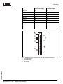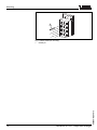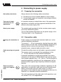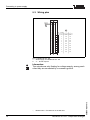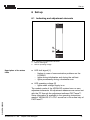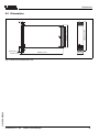
1
Operating Instructions
VEGALOG 571 AA
Output card analogue
!
on
VEGALOG
571 AA
in
out
Contents
Contents
About this document
2
For your safety
3
Product description
4
Mounting
5
Connecting to power supply
6
Set up
7
Maintenance and fault rectification
8
Dismounting
9
Supplement
1.1
1.2
1.3
2.1
2.2
2.3
2.4
2.5
3.1
3.2
3.3
3.4
4.1
4.2
4.3
5.1
5.2
5.3
6.1
7.1
7.2
7.3
8.1
8.2
9.1
9.2
Function . . . . . . . . . . . . . . . . . . . . . . . . . . . . .
Target group . . . . . . . . . . . . . . . . . . . . . . . . . .
Symbolism used . . . . . . . . . . . . . . . . . . . . . . .
3
3
3
.
.
.
.
.
.
.
.
.
.
.
.
.
.
.
.
.
.
.
.
.
.
.
.
.
.
.
.
.
.
.
.
.
.
.
.
.
.
.
.
.
.
.
.
.
.
.
.
.
.
.
.
.
.
.
.
.
.
.
.
.
.
.
.
.
.
.
.
.
.
..
..
..
..
..
4
4
4
4
5
.
.
.
.
.
.
.
.
.
.
.
.
.
.
.
.
.
.
.
.
.
.
.
.
.
.
.
.
.
.
.
.
.
.
.
.
.
.
.
.
.
.
.
.
.
.
.
.
.
.
.
.
.
.
.
.
..
..
..
..
6
6
6
7
General instructions. . . . . . . . . . . . . . . . . . . . .
Module . . . . . . . . . . . . . . . . . . . . . . . . . . . . . .
Coding . . . . . . . . . . . . . . . . . . . . . . . . . . . . . .
8
8
8
Authorised personnel . . . .
Appropriate use. . . . . . . .
Warning about misuse . . .
CE conformity . . . . . . . . .
Environmental instructions
Configuration. . . . . . .
Principle of operation .
Operation . . . . . . . . .
Storage and transport
.
.
.
.
.
.
.
.
.
.
.
.
Preparing the connection . . . . . . . . . . . . . . . . . 11
Connection cable. . . . . . . . . . . . . . . . . . . . . . . 11
Wiring plan . . . . . . . . . . . . . . . . . . . . . . . . . . . 12
Indicating and adjustment elements . . . . . . . . . 13
Maintenance . . . . . . . . . . . . . . . . . . . . . . . . . . 14
Fault rectification . . . . . . . . . . . . . . . . . . . . . . . 14
Instrument repair . . . . . . . . . . . . . . . . . . . . . . . 15
Dismounting procedure . . . . . . . . . . . . . . . . . . 16
Disposal . . . . . . . . . . . . . . . . . . . . . . . . . . . . . 16
Technical data. . . . . . . . . . . . . . . . . . . . . . . . . 17
Dimensions . . . . . . . . . . . . . . . . . . . . . . . . . . . 19
VEGALOG 571 AA - Output card analogue
31949-EN-060606
2
1
About this document
1 About this document
1.1 Function
This operating instructions manual has all the information you
need for quick setup and safe operation. Please read this
manual before you start setup.
1.2 Target group
This operating instructions manual is directed to trained,
qualified personnel. The contents of this manual should be
made available to these personnel and put into practice by
them.
1.3 Symbolism used
Information, tip, note
This symbol indicates helpful additional information.
Caution: If this warning is ignored, faults or
malfunctions can result.
Warning: If this warning is ignored, injury to persons and/or
serious damage to the instrument can result.
Danger: If this warning is ignored, serious injury to persons
and/or destruction of the instrument can result.
31949-EN-060606
Ex applications
This symbol indicates special instructions for Ex applications.
l
List
The dot set in front indicates a list with no implied sequence.
à
Action
This arrow indicates a single action.
1
Sequence
Numbers set in front indicate successive steps in a procedure.
VEGALOG 571 AA - Output card analogue
3
For your safety
2 For your safety
2.1 Authorised personnel
All operations described in this operating instructions manual
must be carried out only by trained specialist personnel
authorised by the operator. For safety and warranty reasons,
any internal work on the instruments must be carried out only
by personnel authorised by the manufacturer.
2.2 Appropriate use
The AA card (Ausgang Analog, i.e. output analog) provides
together with the VEGALOG 571 processing system ten 0/
4 … 20 mA outputs.
2.3 Warning about misuse
Inappropriate or incorrect use of the instrument can give rise to
application-specific hazards, e.g. vessel overfill or damage to
system components through incorrect mounting or adjustment.
2.4 General safety instructions
VEGALOG 571 AA is a high-tech instrument requiring the strict
observance of standard regulations and guidelines. The user
must take note of the safety instructions in this operating
instructions manual, the country-specific installation standards
(e.g. the VDE regulations in Germany) as well as all prevailing
safety regulations and accident prevention rules.
2.5 CE conformity
The VEGALOG 571 AA(Ex) module card is in CE conformity
with EMVG (89/336/EWG) and LVD (73/23/EWG).
Conformity has been judged according to the following
standards:
l
l
LVD: EN 61010
VEGALOG 571 AA - Output card analogue
31949-EN-060606
4
EMC:
- Emission EN 50081-2
- Susceptibility EN 50082-1
For your safety
2.6 Environmental instructions
Protection of the environment is one of our most important
duties. That is why we have introduced an environment
management system with the goal of continuously improving
company environmental protection. The environment management system is certified according to DIN EN ISO 14001.
Please help us fulfil this obligation by observing the environmental instructions in this manual:
l
31949-EN-060606
l
Chapter "Storage and transport"
Chapter "Disposal"
VEGALOG 571 AA - Output card analogue
5
Product description
3 Product description
3.1 Configuration
Scope of delivery
The scope of delivery encompasses:
l
l
19" module card VEGALOG 571 AA
Documentation
- this operating instructions manual
3.2 Principle of operation
Area of application
The AA card (Ausgang Analog, i.e. output analogue) provides
together with the VEGALOG 571 processing system ten 0/
4 … 20 mA outputs. These can be used for transmission of the
measuring results to the following instruments:
l
l
l
l
Indicating instruments
Characteristics recorder
Controller
PLC
Physical principle
The AA card makes the processing results available via up to
ten analogue currents in the range of 0 … 20 mA. A scaling as
well as the definition as rising or falling characteristics can be
set via the adjustment software.
Power supply
The module card is powered via the common power supply
unit of the VEGALOG system.
You can find detailed information on the power supply in the
"Technical data" in the "Supplement".
3.3 Operation
The operation of VEGALOG 571 is carried out via a PC which
can be connected via the RS232 interface of the CPU. As an
alternative, connection via Ethernet and VEGACOM 558 is
possible.
6
VEGALOG 571 AA - Output card analogue
31949-EN-060606
The adjustment software PACTware™ with the corresponding
DTMs is installed under Windows™ and ensures easy
configuration of measuring systems as well as parameter
adjustment of connected VEGA sensors. For this purpose,
PACTware™ provides a clear adjustment interface with menu
structure, window technology and graphic support. In addition,
online help is available which describes the available functions
Product description
and parameter adjustment options. For earlier VEGALOG
systems with CPU software 1.xx, the previous software VVO
(VEGA Visual Operating) must be used for operation.
3.4 Storage and transport
Packaging
Your instrument was protected by packaging during transport.
Its capacity to handle normal loads during transport is assured
by a test according to DIN EN 24180.
The packaging of standard instruments consists of environment-friendly, recyclable cardboard. For special versions, PE
foam or PE foil is also used. Dispose of the packaging material
via specialised recycling companies.
Storage and transport temperature
l
31949-EN-060606
l
Storage and transport temperature see "Supplement Technical data - Ambient conditions"
Relative humidity 20 … 85 %
VEGALOG 571 AA - Output card analogue
7
Mounting
4 Mounting
4.1 General instructions
The module cards of VEGALOG 571 can only be mounted into
the 19" carrier BGT LOG 571. It is provided with a special bus
board for data transmission between CPU and the individual
peripheral cards (LOGBUS). The carrier is designed for
mounting into a switching cabinet or 19" housing.
The plug position for the individual cards is individually
selectable, the system saves the card positions when switching on.
Note:
The plug positions must not be changed after the parameter
adjustment because measurement loops that have already
been set up would otherwise have to be reconfigured.
4.2 Module
Installation instructions
Setup a module for the VEGALOG 571 AA card. You will find
the description in the operating instructions manual "CPU and
carrier".
4.3 Coding
A mechanical coding system avoids later interchanging of the
various module cards in the carrier.
The coding system consists of:
l
l
two coded pins in the female multipoint connector
two holes in the male multipoint connector of the respective
component
The coded pins are attached to the module.
Equip the female multipoint connector with the two coded pins
according to the "Coding chart" and "Position of the coded
pins". The function coding points out that these are module
cards of VEGALOG. The instrument coding is used to
differentiate between the individual module cards.
8
VEGALOG 571 AA - Output card analogue
31949-EN-060606
The male multipoint connectors of the individual module cards
point to the holes suiting the pin positions.
Mounting
Instrument coding
Function coding
CPU card
a1
c3
EP card
a3
c3 and c23 with Ex
AA card
a5
c3
AR card
a7
c3
AT card
a9
c3
EA card
a11
c3
VEGACOM 557
a27
c3, c11
VEGACOM 558
a29
c11
VEGASTAB 593
--
--
1
a1
a3
a5
a7
a9
a11
a13
z b d
a c
o1o
o3o
o5o
c3
2
o7o
o9o
o11o
o13o
c11
o15o
o17o
o19o
a23
a25
a27
o21o
o23o
o25o
3
c23
o27o
o29o
o31o
31949-EN-060606
Fig.
1
2
3
1: Positioning of the coded pins on the male multipoint connector
Instrument coding
Function coding
Ex coding
VEGALOG 571 AA - Output card analogue
9
Mounting
1
Fig. 2: Detail coded pin mounting
1 Coded pin
VEGALOG 571 AA - Output card analogue
31949-EN-060606
10
Connecting to power supply
5 Connecting to power supply
5.1 Preparing the connection
Note safety instructions
Always observe the following safety instructions:
l
l
Connect only in the complete absence of line voltage
If overvoltage surges are expected, overvoltage arresters
should be installed
Take note of safety
instructions for Ex
applications
In hazardous areas you should take note of the appropriate
regulations, conformity and type approval certificates of the
sensors and power supply units.
Select power supply
The module card is powered via the common power supply
unit of the VEGALOG system.
You can find detailed information on the power supply in the
"Technical data" in the "Supplement".
5.2 Connection cable
Selecting the connection cable
Power supply is connected with standard cable acc. to the
national installation standards.
To connect 4 … 20 mA instruments, standard two-wire cable
without screen can be used. If electromagnetic interference is
expected which is above the test values of EN 61326 for
industrial areas, screened cable should be used.
Cable screening and grounding
Connect the cable screen on both ends to ground potential.
The screen must be connected (low impedance) on the
4 … 20 mA instrument to the potential equalisation.
If potential equalisation currents are expected, the screen
connection on the side of VEGALOG 571 AA must be made
via a ceramic capacitor (e.g. 1 nF, 1500 V). The low frequency
potential equalisation currents are thus suppressed, but the
protective effect against high frequency interference signals
remains.
31949-EN-060606
Select connection
cable for Ex applications
Take note of the corresponding installation regulations for Ex
applications. In particular, make sure that no potential equalisation currents flow over the cable screen. In case of
grounding on both sides this can be achieved by the use of a
capacitor or a separate potential equalisation.
The total capacitance of the cable and of all capacitors must
not exceed 10 nF in Ex applications.
VEGALOG 571 AA - Output card analogue
11
Connecting to power supply
5.3 Wiring plan
L (+)
N (-)
1
2
d
b
z
4
6
8
2
10
12
14
16
18
20
22
24
26
28
30
32
+
-
+
-
+
-
+
-
+
-
+
-
+
-
+
-
+
-
+
-
+
-
1
d14
z14
2
d16
z16
3
d18
z18
4
d20
z20
5
d22
z22
6
d24
z24
7
d26
z26
8
d28
z28
9
d30
z30
10
d32
z32
0/4 … 20 mA
Fig. 3: VEGALOG 571 AA1)
1 Power supply for VEGALOG 571 AA
2 4 … 20 mA outputs
Information:
The outputs are only floating for voltage supply, among each
other they are connected by a common ground.
12
Broken lines = Connections on the AA card.
VEGALOG 571 AA - Output card analogue
31949-EN-060606
1)
Set up
6 Set up
6.1 Indicating and adjustment elements
1
2
!
on
VEGALOG
571
Fig. 4: Indicating and adjustment elements
1 LED for fault signal
2 LED for operating voltage
Description of the status
LEDs
l
l
LED fault signal [1]
- flashes in case of communication problems on the
LOGBUS
- lights during initialisation and during the self-test
- lights permanently during a hardware error
LED operating voltage [2]
- lights when voltage supply is on
31949-EN-060606
The module cards of the VEGALOG system have no own
adjustment elements. All adjustment measures are carried out
with the PC through the adjustment software PACTware™.
Setup information is available in the operating instructions
manual "VEGALOG 571 CPU" as well as in the online help of
PACTware™.
VEGALOG 571 AA - Output card analogue
13
Maintenance and fault rectification
7 Maintenance and fault rectification
7.1 Maintenance
When used as directed in normal operation, the module card
VEGALOG 571 AA is completely maintenance-free.
7.2 Fault rectification
Causes of malfunction
VEGALOG 571 AA offers maximum reliability. Nevertheless
faults can occur during operation. These may be caused by the
following, e.g.:
l
l
l
Fault rectification
Measured value of the sensor not correct
Voltage supply
Interference on the cables
The first measures to be taken are checking the input/outout
signal as well as processing failure messages. The diagnostic
information are updated cyclically in a 5 sec. pattern.
PACTware™ with the suitable DTM offers comprehensive
diagnostics options. The integrated online help offers you
additional information. In many cases, these causes can be
thus determined and faults can be rectified.
24 hour service hotline
If these measures are not successful, you can call the VEGA
service hotline in urgent cases under the phone no.
+49 1805 858550.
The hotline is available to you 7 days a week round-the-clock.
Since we offer this service world-wide, the support is only
available in the English language. The service is free of
charge, only the standard telephone costs will be charged.
Fault messages via LED status indication
The operating condition of the CPU and peripheral cards is
displayed via the status LEDs in the front plate.
l
l
LED operating voltage (green)
- lights when voltage supply is on
VEGALOG 571 AA - Output card analogue
31949-EN-060606
14
LED failure message (red)
- flashes in case of communication problems on the
LOGBUS
- lights during initialisation and during the self-test
- lights permanently during a hardware error
Maintenance and fault rectification
7.3 Instrument repair
If a repair is necessary, please proceed as follows:
You can download a return form (23 KB) from our homepage
www.vega.com under: "Downloads - Forms and Certificates Repair form".
By doing this you help us carry out the repair quickly and
without having to call back for needed information.
l
l
l
31949-EN-060606
l
Print and fill out one form per instrument
Clean the instrument and pack it damage-proof
Attach the completed form and possibly also a safety data
sheet to the instrument
Please request the address for the return shipment from
the VEGA agency serving you.
VEGALOG 571 AA - Output card analogue
15
Dismounting
8 Dismounting
8.1 Dismounting procedure
Warning:
Before dismounting, be aware of dangerous process conditions such as e.g. pressure in the vessel, high temperatures,
corrosive or toxic products etc.
Take note of chapters "Mounting" and "Connecting to power
supply" and carry out the listed steps in reverse order.
8.2 Disposal
The instrument consists of materials which can be recycled by
specialised recycling companies. We use recyclable materials
and have designed the electronic modules to be easily
separable.
WEEE directive 2002/96/EG
This instrument is not subject to the WEEE directive 2002/96/
EG and the respective national laws (in Germany, e.g.
ElektroG). Pass the instrument directly on to a specialised
recycling company and do not use the municipal collecting
points. These may be used only for privately used products
according to the WEEE directive.
Correct disposal avoids negative effects to persons and
environment and ensures recycling of useful raw materials.
Materials: see "Technical data"
If you cannot dispose of the instrument properly, please
contact us about disposal methods or return.
VEGALOG 571 AA - Output card analogue
31949-EN-060606
16
Supplement
9 Supplement
9.1 Technical data
General data
Series
Dimensions
Weight
Voltage supply
Operating voltage (PIN d2, z2)
Power consumption
Electrical connection
Module card
Module in the carrier BGT LOG 571
Current outputs
19" module card for BGT LOG 571
W = 25.4 mm (1 in), H = 128.4 mm (5.06 in), D
= 166 mm (6.54 in)
approx. 400 g (0.882 lbs)
24 V DC (18 … 36 V)
max. 9 W
Multipoint connector according to DIN 41612,
series F, 48-pole (d, b, z) with coding hole
Suitable female multipoint connector according
to DIN 41612 with connection via standard
connection technologies
Quantity
10 outputs
Range
0/4 … 20 mA
Function
Resolution
analogue output of the processing results
0.05 % of range (10 µA)
Max. load
750 Ohm
Linearity error
0.025 % of range
Load-dependent error at 750 Ohm
Temperature error
0.5 % (100 µA)
0.025 %/10 k of range
Displays
LED displays
- Status indication operating voltage
31949-EN-060606
-
Status indication fault signal
Ambient conditions
Ambient temperature
Storage and transport temperature
VEGALOG 571 AA - Output card analogue
1x LED green
1x LED red
-20 … +60 °C (-4 … +140 °F)
-20 … +80 °C (-4 … +176 °F)
17
Supplement
Electrical protective measures
Protection mounted in BGT LOG 571
- front side completely equipped or
covers
-
Upper and lower side
Wiring side
IP 20
IP 00
Protection class
I (in carrier BGT LOG 571)
Overvoltage category
II
Electrical separating measures
Galvanic separation according to
VDE 0106, part 12)
- Reference voltage
between voltage supply, LOGBUS connection
and current outputs
250 V
All current outputs have a common reference potential (GND).
VEGALOG 571 AA - Output card analogue
31949-EN-060606
2)
18
IP 40
Supplement
100mm (3 15/16")
128,4mm (5 1/16")
9.2 Dimensions
!
on
VEGALOG
571
9mm (23/64")
5,5mm (7/32")
162mm (6 3/8")
5 TE
25,4mm
(1")
31949-EN-060606
Fig. 5: Dimensions VEGALOG 571 AA
VEGALOG 571 AA - Output card analogue
19
VEGA Grieshaber KG
Am Hohenstein 113
77761 Schiltach
Germany
Phone +49 7836 50-0
Fax +49 7836 50-201
E-mail: [email protected]
www.vega.com
ISO 9001
All statements concerning scope of delivery, application,
practical use and operating conditions of the sensors and
processing systems correspond to the information available at the time of printing.
© VEGA Grieshaber KG, Schiltach/Germany 2006
Technical data subject to alterations
31949-EN-060606