1
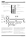
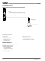
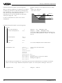
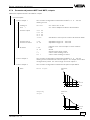
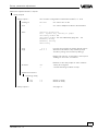
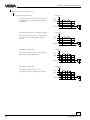
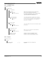
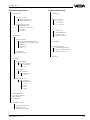
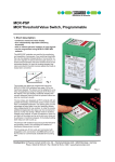
Level and Pressure
Operating Instruction
VEGAMET 514… D
%
100
-
+
ESC
OK
CONNECT
2
1
on
514 D
in
out
Contents
Contents
Safety information ....................................................................................... 2
1
2
3
Product description
1.1
Function and configuration ................................................................ 4
1.2
Types and versions ............................................................................ 5
1.3
Applications ....................................................................................... 6
1.4
Technical data .................................................................................... 7
1.5
Dimensions ....................................................................................... 10
1.6
Ex-technical data ............................................................................. 11
1.7
Approvals ......................................................................................... 11
Mounting
2.1
Mounting versions ............................................................................ 12
2.2
Instrument address .......................................................................... 13
Electrical connection ......................................................................... 14
Safety information
The described module must only be inser ted and
operated as described in this operating instruction.
Please note that other action can cause damage for
which VEGA does not take responsibility.
2
VEGAMET 514… D
Contents
4
Set-up
4.1
Indicating and operating elements ................................................. 15
4.2
Adjustment system ........................................................................... 16
4.3
Menu list ........................................................................................... 17
4.4
Adjustment via PC ............................................................................ 18
4.5
Set-up sequence .............................................................................. 18
4.6
4.7
4.8
5
Set-up, configuration ....................................................................... 19
4.6.1
Configuration inputs ............................................................ 19
4.6.2
Configuration meas. point .................................................. 21
4.6.3
Configuration output ........................................................... 23
Set-up, parameter adjustment ......................................................... 26
4.7.1
Parameter adjustment MST1, adjustment .......................... 26
4.7.2
Flow measurement .............................................................. 28
4.7.3
Parameter adjustment MST1 and MST2, processing ........ 33
4.7.4
Parameter adjustment MST1 and MST2, outputs .............. 35
4.7.5
Parameter adjustment MST1 and MST2, simulation .......... 42
4.7.6
Parameter adjustment MST1 and MST2, special functions 43
Set-up, additional functions ............................................................. 43
4.8.1
Password ............................................................................. 43
4.8.2
Linearization curve 1 … 3 ................................................... 43
4.8.3
Info ....................................................................................... 44
4.8.4
Language ............................................................................ 44
4.8.5
VEGAMET Reset ................................................................. 45
4.8.6
Service ................................................................................. 45
Diagnosis
5.1
Detailled menu list ............................................................................ 46
5.2
Maintenance ..................................................................................... 48
5.3
Repair ............................................................................................... 48
5.4
Fault signal ....................................................................................... 48
5.5
Error codes ....................................................................................... 49
VEGAMET 514… D
3
Product description
1 Product description
1.1 Function and configuration
Configuration
VEGAMET 514 D and 514 DV signal conditioning
instruments are designed for flow measurement.
The signal conditioning instruments are
microcomputer controlled and consist of software
components.
Function
Mechanically the signal conditioning instruments are
designed in 19"-technology (width 5 TE = 24,5 mm).
Flow measurement in flumes
Flumes or their throat cause a reflux of the measured
product. The flow can be determined out of the
appropriate levels.
Sensors detect levels and deliver analog or digital
measured data to connected VEGAMET.
In the signal conditioning instruments the parameter
"flow" is generated out of the measured data.
The output result is provided as current, volt and
relay output as well as digital signal output
(DISBUS).
The current and relay outputs are sometimes
provided with a flow specific preconfiguration.
Sketch
AB
Output components
mA
Function components
V
Parameter for
- meas. point 1 (MST1)
- meas. point 2 (MST2)
Current outputs 0 … 20 mA
Voltage outputs 0 … 10 V
AB
Relay outputs 1 … 2
Display
Application
- Sensor
- Kind
- Option
- Sensor position A … D
AB
FB
Display
1
2
Digital signal output
- PC/DCS-output
- DISBUS-output
AB
PC
DIS
Input components
EB
EB
1
4
Correction signal input
- input 4
- channel no. K1
Sensor input
- input 1
- channel no. S1 or
- series no of sensor 1
4
VEGAMET 514… D
Product description
Examplary application
- flow measurement in a flume
- with offset correction (by additional sensor)
Inputs
A
- input 1 and 4
- channel no. S1 and K1
no. 1 S1
no. 4 K1
D
Sensor
- offset correction signal in pos. D
- sensor 1 in pos. A
Meas. points
Parameter
- MST1 = A
- MST2 = A
- level
- flow
1.2 Types and versions
According to the application and the appropriate
sensor the type and version of the signal
conditioning instrument can be determined.
VEGAMET for sensors with analog measured data
transmission
- hydrostatic pressure transmitter
Number of
Number of outpouts
inputs
Sensor Correct. mA
V
DIS
signal
VEGAMET
514 D…
…
1
1
3
3
2
1
Number of
Number of outputs
inputs
Sensor Correct. mA
V
DIS
signal
VEGAMET
1
Ex = Signal conditioning instrument for meas. systems
in hazardous areas, certificate to CENELEC
VEGAMET 514… D
VEGAMET for sensors with digital measured data
transmission (VBUS)
- hydrostatic pressure transmitter
- ultrasonic sensor
- radar sensor
514 DV
1
1
3
3
2
1
1
5
Product description
1.3 Applications
Flow measurement
Standard
Application:
Sensor:
Kind:
Option:
Parameter:
A
A
Flow
Hydrostatic pressure transmitter
Ultrasonic sensors
Radar sensors
Level
Offset correction (only with hydr. pressure transmitter)
MST1 level
MST2 flow
A
Fig. 1.2 Flow measurement
Option
A key connected to the correction input corrects the output results when
being set to zero.
Offset correction
- in empty flume
- preferably manually with key
- parallel shifting of the
adjustment characteristics
- effects MST1 and MST2
A
actual measured value in
%
100 %
incorrect course of measured
values
measured value too low
measured value too high
D
0
0
100 %
corrected measured value e.g. 0 % (m3/
h)
Fig. 1.13 Correction in the point
6
VEGAMET 514… D
Product description
1.4 Technical data
Power supply
= 24 V AC (20 … 53 V), 50/60 Hz
= 24 V DC (20 … 72 V)
Operating voltage
U nenn
Power consumption
- VEGAMET 514 D
- VEGAMET 514 VD
Fuse
appr. 7 VA or appr. 5 W
appr. 17 VA or appr. 12 W
630 mA slow-blow
Measuring data input VEGAMET 514 D
Number
Kind of input
Range
Voltage
Current limitation
Detection-line interruption
Detection-line shortcircuit
Min. adjustment delta
Connection line
Resistance per conductor
Resolution
Linearity error
Temperature error
1 input
active two-wire input, analog
4 … 20 mA
hydrostatic pressure transmitters
at 4 mA appr. 18 V DC, at 20 mA appr. 15 V DC
at appr. 26 mA, shortcircuit proof
< 2 mA
> 23 mA
2 % of the adjusted sensor values
2-wire (standard line)
max. 35 Ω
1 µA
0,025 % at 4 … 20 mA
0,04 %/10 K at 4 … 20 mA
Measuring data input VEGAMET 514 VD
Number
Data transmission
Sensor
Voltage
Power limitation
Connection line
Line length
Resistance per conductor
1 input
digital (VBUS)
hydrostatic pressure transmitters,
ultrasonic or radar sensor
appr. 25 V DC
at appr. 7 W, shortcircuit proof
2-wire (screened)
max. 1000 m
max. 200 Ω for hydrostatic pressure transmitters
max. 20 Ω for ultrasonic or radar sensors
Correction signal input
Number
Function
Voltage
Current
External line resistor
1 input
switching signal to trigger and offset correction
5 V (from instrument)
5 mA
≤ 150 Ω
>>
VEGAMET 514… D
7
Product description
Current output
Number
Function
Output values
- level / flow proportional
Load
Range
Resolution
Linearity error
Temperature error
- pulse output
Load
Voltage pulse
Pulse length
3 outputs
current output 2 and 3 can be configured and
parameter adjusted as:
- level proportional
- flow proportional
- flow pulses
- sampling pulse
max. 500 Ω
0/4 … 20 mA
0,05 % of range
0,05 % of range
0,05 %/10 k of range
min. 600 Ω
12 V DC at 20 mA
200 ms
Voltage output
Number
Function
Range
Current
Resolution
Linearity error
Temperature error
3 outputs
analog output of the output results
0/2 … 10 V
max. 1 mA
0,05 % of range
0,05 % of range
0,06 %/10 k of range
Relay outputs
Number
Function
Contact
Turn-on voltage
Switching current
Breaking capacity
Min. switching hysteresis (Low/High-Delta)
2 switching relays
1 fail dafe relay
can be configured and parameter adjusted as:
- switching relay for level or flow
- pulse relay-flow quantity
- pulse relay-sampling
1 floating spdt
AgNiO and hard gold plated
min. 10 mV DC
max. 250 V AC/DC
min. 10 µA
max. 3 A AC, 1 A DC
max. 500 VA, 54 W
0,5 %
DISBUS-output
Function
Connection line
Line length
digital transmission of output results and
system information to VEGADIS 174 or
VEGACOM 557
2-wire
max. 1000 m
>>
8
VEGAMET 514… D
Product description
Indicating element
Clear text indication
Analog indication
LED in front plate
LC-display
- 4 line, 6 figures each
- background lightning
11 segments 0 % … 100 %
acc. to MST-enquiry
- %-value of level
- %-value of flow
green on: operating voltage on
red: fault signal
yellow (per relay): relay switching condition
Operating elements
Front plate
6 keys for configuration and parameter adjustment
Ambient conditions
Permissible ambient temperature
Storage and transport temperature
-20°C … +60°C
-40°C … +80°C
Electrical connection
Multipoint connector component
Carrier BGT 596 (Ex)
Housing type 505
acc. to DIN 41 612, series F, 36-pole (three row) d, b, z
(partly equipped)
connection to the respective module
connection to screw terminals (max. 2,5 mm2 )
Electrical protective measures
Protection
- unassembled
- mounted into
- mounted into housing
- terminal housing
- housing general
Protection
Overvoltage category
IP 00
carrier BGT 596
front side completely equipped: IP 40
upper and lower side: IP 20
wiring side: IP 00
IP 20
IP 30
II (in housing type 505 or type 506)
II
Electrical separating measures
Reliable separation acc. to VDE 0106,
part 1
- limit voltage
- isolation resistance
between power supply, fail safe and level relay,
meas. data inputs and correction inputs
250 V
2,3 kV
Galvanic separation
- limit voltage
- isolation resistance
between relay outputs
250 V
1,4 kV
Potential separation
inputs
- limit voltage
- isolation resistance
Common reference potential at
between DISBUS, transistor outputs and correction
50 V
0,5 kV
voltage/current outputs, correction inputs
>>
VEGAMET 514… D
9
Product description
Mechanical data
Series
Dimensions unassembled
module instrument for carrier BGT 596
or housing type 505 or type 506
W = 25, 4 mm (5 TE), H = 128,4 mm, D = 162 mm
CE-approval, conformity judgement
VEGAMET signal conditioning instruments meets the protective regulations of EMVG (89/336/EWG) and
NSR (73/23/EWG). The conformity has been judged by means of a typical configuration acc. to the
following standards:
EMVG
Emission
EN 50 081 - 2: 1993
Immission
EN 50 082 - 2: 1995
NSR
EN 61 010 - 1: 1993
1.5 Dimensions
Circuit board 100 x 160 x 1,5
European size
5 TE
Multiple plug
%
+
128,4
100
100
-
OK
ESC
CONNECT
1
2
on
514 D
Ser.No.12345678
3
9
14,5
162
25
>>
10
VEGAMET 514… D
Product description
1.6 Ex-technical data
Power supply
Operating voltage
Limit voltage
U nenn corresponds to the not-Ex-version
U nenn = 250 V AC or 125 V DC
Measuring data input (intrinsically safe circuit)
Classification
Max. values
- Voltage
- Current
- Power
Characteristics
Effective inner inductance L i
Effective inner capacitance Ci
[EEx ia] IIC, [EEx ia] IIB, [EEx ib] IIC or [EEx ib] IIB
U O = 20 V
IO = 128 mA
P O = 640 mW
linear
unimportant
unimportant
EEx ia IIB
EEx ib IIC
EEx ib IIB
Max. permissible outer inductance LO (mH)
0,5
EEx ia IIC
1
1,5
2
2
9
Max. permissible out capacitance CO (nF)
97
78
68
486
200
1000
The intrinsically safe circuits are reliably separated from the not-intrinsically safe circuits up to a peak
value of the nominal voltage of 375 V.
The max. voltage on the not-intrinsically safe circuits must not exceed 250 Veff in case of failure.
1.7 Approvals
VEGAMET are available with the following approvals:
- Explosions protection: appropriate operating instrument with intrinsically safe(s)
- Overfill protection to WHG and VbF applied
Observe with these applications the appropriate legal documents (test certificates, type approvals and
conformity certificates). These are supplied with the respective instrument.
WHG-approval
Signal conditioning instrument as part of an overfill protection to WHG or VbF (applied).
Ex-approval
For hazardous areas, certificate to CENELEC defined in the conformity certificate PTB-no. Ex-95.D.2161 X.
VEGAMET 514… D
11
Mounting
2 Mounting
2.1 Mounting versions
Coding
VEGAMET 514 D … 514 VD signal conditioning
instruments can be either mounted with a module in
a carrier BGT 596 or BGT 596 Ex.M or in a single
housing type 505 or type 506.
To avoid interchanging of the various signal
conditioning instruments, the multipoint connector of
the carrier or the housing is provided with pins and
the multiple plug of the signal conditioning
instrument with holes (mechanical coding).
Module
Multipoint connector DIN 41 612, series F, 33-pole
(d, b, z) with coded pins and mounting material for
mounting in carrier BGT 596 or BGT 596 Ex.M.
An Ex-coding with fixed coded pin ensures that notEx and Ex-instruments are not interchanged.
Module Ex
Multipoint connector DIN 41 612, series F, 33-pole
(d, b, z) with coded pins, Ex-separating chamber
and mounting material for mounting in carrier
BGT 596 Ex.M.
Single housing
Plastic housing type 505 or type 506 for single
mounting of signal conditioning instruments with a
width of 5 TE (25,4 mm).
An instrument coding ensures that the various signal
conditioning instruments are not interchanged. The
respective coded pins are attached to each module
or housing. Provide the multipoint connector with
these coded pins acc. to the following schedule and
figure.
Instrument
coding
VEGAMET 514 D
a5 / c5
VEGAMET 514 D Ex
a5 / c5
Mount the respective module (standard or Exversion) in the carrier. Wire the connections of the
multipoint connector according to the wiring plan on
page 14.
VEGAMET 514 VD
a7 / c5
The multipoint connector is available as follows:
- Wire-Wrap standard connection 1,0 x 1,0 mm
- plug connection 2,8 x 0,8 mm
- Termi-Point Standard connection 1,6 x 0,8 mm
- soldering connection
- screw terminals 2 x 0,5 mm 2
Instrument coding
Mounting carrier
c23
Fig. 2.1 Coding schedule
z b d
Function coding
a c
o1o
o3o
514 D a5
514 VD a7
o5o
c5
VEGAMET
o7o
o9o
For further information concerning mounting see
operating instruction of the carrier.
o11o
Mounting single housing
o17o
You can either screw the housing socket directly to
the mounting plate or plug on a carrier rail
(TS 35 x 7,5 acc. to EN 50 022 or TS 32 acc. toEN
50 035). Connect the terminals according to the
wiring plans on the following pages. For further
information to the mounting see operating instruction
of the housing.
Excoding
o13o
o15o
o19o
o21o
o23o
c23 Ex-coding
o25o
o27o
o29o
o31o
Transparent cover
To protect the housing against unauthorized
operation, the front plate of VEGAMET can be
provided with a lockable transparent cover.
12
Fig. 2.2 Module coding, VEGAMET
VEGAMET 514… D
Mounting
Ex-version
Mounting in carriers
If you mount your VEGAMET with Ex-approval in a
carrier, you have to use a VEGA-Ex-module. Keep a
distance of at least 10 mm (2 TE) to modules of other
manufacturers. If you want to mount the VEGAMET in
the extreme left position in the carrier, you have to
mount a blind cover of at least 20 mm (4 TE) in front
of the module of the instrument.
Note!
Signal conditioning instruments must be generally
mounted outside hazardous areas or special Exprotective measures must be taken.
Ex-separating chamber
To ensure sufficient "air and creeping distances", an
Ex-separating chamber must be mounted to the
connections of VEGAMET. Lead the wires through the
Ex-separating chamber and connect them. Fasten
the Ex-separating chamber with the lower screw.
Observe the operating instrumention of carrier
BGT 596 Ex.M.
%
100
+
-
Protection for Ex-applications
In Ex-applications a protection of IP 20 must be kept.
Cover the spaces or not used modules from the front
by appropriate blind covers.
OK
ESC
CONNECT
on
VEGAMET
515 N
Blind cover
2.2 Instrument address
Adjust the instrument address on the appropriate switch on the circuit board. Address range 1 ...15. Observe
that no address is used twice. Factory setting = instrument address 0.
514 VD
Switch
A
3 4 5 6
7 8 9
2
B C DE
corresp.
10
11
12
13
14
15
514 D Ex
Switch on bottom, visible through
an appropriate opening
F 0 1
Under the menu point "Instrument address" ´the
adjustment carried out on the switch can be
indicated.
VEGAMET 514… D
13
Electrical connection
3 Electrical connection
VEGAMET 514 D, 514 D Ex
VEGAMET 514 VD
Supply
voltage
L (+)
N (-)
d b
2 +
z
-
6
Fail safe relay
10
Relay output 1
12
Relay output 2
1
16 +
Current outputs 1 … 3
Voltage output 1 … 3
Correction
signal input 4
Ex-version
For connection of Ex-certified instruments observe
the instructions in the attached legal documents as
well as in the valid mounting instructions. Note that
the Ex-separating chamber is mounted on the
multipoint connector.Always lead the wires through
the Ex-separating chamber. Observe the operating
instruction of the carrier BGT 596 Ex.M and the Exinstructions.
2
3
18 20 +
22 +
+
-
-
24
DISBUS-output
28
+
+
30
-
32
-
Sensor
14
VEGAMET 514… D
Set-up
4 Set-up
4.1 Indicating and operating elements
Signal conditioning instrument
with adjustment module
1
2
%
3
5
7
10
11
12
13
14
1
18
1
2
16
Lockable fixing screw
Display (4 lines with 6 figures each,
illuminated)
3…8
See following page
9 Analog indication 11-digit
10 Connection for VEGACONNECT
connection cable
11 LED relay output 1 and 2
12 LED fault signal
VEGAMET 514… D
15
[17]
100
-
+
ESC
OK
4
6
CONNECT
8
9
2
1
!
on
514
Ser.No.12345678
Fig. 4.1
13
14
15
16
LED supply voltage
Ledge
Multiple plug with wiring plan
Position of the switch for adjustment
of the instrument address [17] on
VEGAMET 514 D Ex
18 Transparent cover
15
Set-up
4.2 Adjustment system
Indicating and adjustment module
Indication of
- measured value
- menu points
- parameters
- values
Branch, i.e. jump to the lower menu
[OK]
Acc. to the parameter, change value or
select from list
%
100
-
Select menu point
+
Acc. to the menu point delete the
adjustment or change to the
upper menu
Acc. to the menu point store the
adjusted value or change to the lower
menu
ESC
OK
Analog indication
Menu tree
MST1
MST2
%
Indication of
measured values
Main
menu
Sub
menu
%
36.9
Param.
MST1
Param.
MST2
OK
Adjustment
Processing
Output
Simulation
Scaling
Lin.
curve
Integration
time
10
The adjustment is menu oriented and is made via six
keys in conjunction with clear text indication. The
jump from indication of measured values to the main
menu is made with [OK]. Use [→] or [←] to change
within the main menu from one menu point to the
other.
A branch is indicated by the symbol
and ensures
with [OK] a jump to the lower menu. In each menu
are thematically combined parameters (possibly in
further sub menus).
16
add.
functions
Configuration
ESC
Inputs
Meas.
point
Outputs
Password
off
Menu point
Parameter
value
Parameters are indicated by the missing symbol
.
The value of the parameters can be modified or
selected out of a list by [+] or [–]. The modified value
can be stored with [OK]. Push [ESC] to interrupt an
adjustment (without storing the modfication).
Certain parameters can be only indicated, however
their value cannot be modified.
Reset to the upper menu is made with [ESC].
60 minutes after a key is pushed for the last time, an
automatic reset to the indication of measured values.
VEGAMET 514… D
Set-up
4.3 Menu list
Values must be adjusted or modified to determine
the meas. points. This determination is made
separately for each meas. point by the following
parameter adjustments.
Adjustments and coordinations must be provided to
determine the instrument functions. This
determination is made by the following
configurations.
Parameter adjustment MST1
Configuration
–– Adjustment
–– with level
–– without level
–– Processing
–– Scaling (level)
–– Lin. curves
–– Integration time
–– Outputs
–– Current outputs
–– Volt outputs
–– Relay outputs
–– MET-indication
–– PC- / PLC-outputs
–– DIS-outputs
–– Simulation
–– Special functions
Parameter adjustment MST2
–– Adjustment
–– with flow
–– without flow
–– Processing
–– Scaling (flow)
–– Lin. curves
–– Integration time
–– Configuration
Inputs, Sensor connections, mark
–– Input 1
–– Input 4
–– Configuration meas. points
–– Application
–– Sensor
–– Kind
–– Options
–– Sensor coordination
–– Instrument address
–– Configuration outputs
–– Current outputs
–– Volt outputs
–– Relay outputs
–– PC- / PLC-output
–– VEGADIS-output
Under the section "Additional functions" all superset
instrument functions, i.e. their adjustment and
coordination possibilities are composed.
Additional functions
–– Password
–– Edit lin. curves
–– Outputs
–– Current outputs
–– Volt outputs
–– Relay outputs
–– Display
–– PC / PLC
–– DISBUS-output
–– Info
––
––
––
––
–– Simulation
–– Reset VEGAMET
–– Reset configuration
–– Reset sensor characteristic values
–– Reset lin. curves
–– Special functions
Input info
VEGAMET-Info
Program info
Meas. point info
–– Language
–– Service
VEGAMET 514… D
17
Set-up
4.4 Adjustment via PC
Signal conditioning instrument with operating module
%
100
+
-
OK
ESC
Set-up
- directly via the keys of the adjustment module
(see following descriptions)
- or with a PC, provided with VVO-Software (VEGA
Visual Operating), and a VEGACONNECT
connection cable
CONNECT
2
1
!
on
515
Ser.No.12345678
VEGACONNECT
connection cable
PC with VVO-Software
4.5 Set-up sequence
Configuration
Additional functions
-
- edit linearization curves
- change language (if necessary)
- activate password (if necessary)
adjust instrument address
configure inputs
prepare meas. points
coordinate outputs
Parameter adjustment
If you want to detect the level and the flow as
parameter, it is recommended, to carry out the
adjustment for MST1 and MST2 at the same time i.e.
immediately one after the other.
- Parameter adjustment MST1
- carry out adjustment
- determine the processing
- define outputs
- Parameter adjustment MST2
as described above
18
VEGAMET 514… D
Set-up, configuration
4.6 Set-up, configuration
4.6.1
Configuration inputs
The inputs of the signal conditioning instruments are
configured according to the ordered instrument
version. Therefore no activities from your side are
necessary. However should there be a modification
necessary, you will find some explanations and
connection examples in the following.
The signal conditioning instruments are either
connected directly to the sensors or they receive
measured data from other sensors via the DISBUSconnection.
VEGAMET 514 D
- Sensors connected directly to VEGAMET
Marking:
The sensor must be marked via its sensor
characteristics values (only hydrostatic pressure
transmitters).
Sensor
characteristics values
VEGAMET 514 VD
- Sensors connected directly to VEGAMET
Marking:
The sensor must be marked with its series
number.
A
Sensor
series
number
D
K1
Connection example 1
A
Connection example 2
Pos. A – input 1, series number 8888.8888
Pos. D – input 4, channel K1
D
S1
K1
Pos. A – input 1, channel S1
Pos. D – input 4, channel K1
>>
VEGAMET 514… D
19
Set-up, configuration
Connection example 1
Configuration, inputs
–– Input 1
Sensor with analog transmission of measured data
–– Input of
this MET
–– Channel no.
S1
–– Sensor characteristics values
––
––
––
––
Min. meas. range
Max. meas. range
Min. sensor value
Max. sensor value
–– Input 4
–– Input of
–– Channel no.
0.00
1.00
4.000
20.000
The menu point "Sensor characteristics values" is
only visible with hydrostatic pressure transmitters.
Meas. range and sensor values are stated in the
test certificate of the hydrostatic pressure
transmitter.
Correction signal (key)
this MET
K1
Connection example 2
Configuration, inputs
–– Input 1
–– Input of
–– Sensor adaption
this MET
–– Input 4
–– Input of
–– Channel no.
this MET
20
Sensor with digital transmission of measured data
can be necessary for ultrasonic / radar sensors (see
BA of the appropriate sensor)
Correction signal (key)
K1
VEGAMET 514… D
Set-up, configuration
4.6.2
Configuration meas. point
VEGAMET 514 D and 514 VD signal conditioning instruments in their basic configuration are designed for
combi application, i.e.
- MST1, level
- MST2, flow measurement
Supplementary the following modifications of the configuration can be carried out.
Configuration meas. point
–– Combi application
–– Application
–– Sensor
–– Kind
–– Options
–– Sensor coordination
–– Position A
–– Position D
–– MST1 level
–– MST name
flow
Hydrostatic
Standard
If a general modification of the basic configuration
should be necessary, a "Reset to combi application"
should be carried out, see respective menu point on
page 44. A new basic configuration can be then
programmed acc. to the product description 1.3
(see page 6).
no
offset corr.
(for MST1 and MST2)
Input 1
A
Channel no.
S1
Input 4
Channel no.
K1
Input 1
Input 4
MST
name
Providing of a special
MST name e.g.
MST
name
level
MST1
–– Fault signal
on
off
on means that a failure of MST1 is transmitted
to the failure processing off means no
transmission
–– Tare
see page 21
–– Monitoring
see page 21
–– MST2 flow
–– MST name
MST
name
Providing of a special
MST name, e.g.
MST
name
flow
MST2
–– Fault signal
as above, however MST2
–– Monitoring
see page 21
VEGAMET 514… D
21
Set-up, configuration
Tare
By means of the tare function an additional
measured value exists from the actual value
beginning at 0%. The tare function can be triggered
via a key connected to correction signal input 4.
Each current, voltage or relay output as well as the
display can be afterwards coordinated to the tared
measured value in the menu point "relating to". With
the allocation or allocations the tared measured
value is activated.
Measured values in %
tared course
actual course
100 %
Key
40
0
0
40
100 %
actual measured values
tared measured values
–– MST1
–– Tare
–– Input
not defined
Input 4
Determination of the correction signal input (key)
Monitoring
For the activation of the monitoring the following prerequirements must be met:
- Determine in the menu range "Configuration
meas. point" input 4
- Connect the key switch (opener) to input 4 (see
page 13).
- Select in the menu range "Parameter adjustment
relay outputs" the monitoring mode for the
concerned relay (see page 37 and 40).
Meas.value
50 %
High 7 % >57 %
<45%
Low –5 %
Relay energized
Relay deenergized
Relay deenergized
The selected relay is energized.
By pushing the key switch (opener opens) the respectively actual measured value is frozen and derived from
this, in case the value is decreased (low) or exceeded (high) the relay energizes.
After a reset and pushing the key switch again the actual measured value is frozen again etc.
–– MST1
–– Monitoring
–– Input
–– MST2
22
not defined
Input 4
with input 4 determination of the correction signal
input (key switch)
as described above
VEGAMET 514… D
Set-up, configuration
4.6.3
Configuration output
Dependent on the basic configuration the outputs are automatically coordinated to the measuring points
MST1 and MST2. This coordination can be modified separately for each output.
In a list either the measuring point numbers MST1 and MST2 or the previously adjusted measuring point
names are provided as choice. In addition each output can be switched off (--), i.e. the switched off output
does not access to any measuring point.
Configuration, outputs
Coordination acc. to basic configuration:
–– Configuration current outputs
–– Current 1 to
MST1
MST2
--
––– 0 … 20 mA level proportional
–– Current 2 to
MST2
-MST1
––– 0 … 20 mA flow proportional
–– Kind 2
Standard
Pulses
––
–– Current 3 to
MST2
-MST1
––– Flow pulses
–– Kind 3
Standard
Pulsed
–– Configuration volt outputs
–– Volt 1 to
––
MST1
MST2
--
––– 0 … 10 V level proportional
–– Volt 2 to
MST2
-MST1
––– 0 … 10 V flow proportional
–– Volt 3 to
-MST1
MST2
––– not coordinated to a MST
>>
VEGAMET 514… D
23
Set-up, configuration
Configuration, outputs
–– Configuration relay outputs
–– Operating relay
–– Relay 1 to
MST1
–– Relay 1 kind
Standard
acc. to basic configuration coordinated to level
Parameter
Hold function
High
Low
Taster
t
d b z
Relay outp.
Reset of alarm
funct.
Parameter
High
Low
Taster
t
d b z
Relay outp.
The relay modes "Hold function" and "Reset of alarm
functions" are configured as described above and
activated with one external signal each (correction
signal input).
–– Input
not defined
Input 4
Determination of the correction signal input
(key, see above)
–– Relay 2 to
MST2
acc. to basic configuration coordinated to flow
–– Relay 2 kind
Standard
Pulses
see Parameter adjustment page 41
–– Fail safe relay kind
–– Input
Standard
The fail safe relay can be operated like the
Hold funct. operating relay, i.e. as described above.
Reset of
alarm funct.
not defined
Input 4
as scribed above
>>
24
VEGAMET 514… D
Set-up, configuration
Configuration, outputs
–– Configuration PC/PLC
–– PC-/PLC-measured values
–– PLC 1 to
–– PLC 2 to
–– PLC 3 to
–– PLC 4 to
–– PLC 5 to
–– PLC 6 to
–– PLC 7 to
Dependent on the basic configuration outputs
are automatically coordinated to measuring points
MST1 and MST2.
MST1
MST2
------
This coordination can be modified separately
for each output. In a list either the measuring
point numbers MST1 and MST2 or the
previously adjusted measuring point names
are available as a choice.
Example acc. to configuration measuring point
MST
name
level
MST
name
flow
–– PC/PLC relay status
off
on
–– PC/PLC Inp. status
off
on
In addition each output can be switched off
(– –), i.e. the switched off output does not access to
any measuring point.
–– Configuration VEGADIS
–– PC-/PLC-measured values
–– DIS 1 to
–– DIS 2 to
–– DIS 3 to
–– DIS 4 to
–– DIS 5 to
–– DIS 6 to
–– DIS 7 to
MST1
MST2
------
Configuration as abobe
Parameter adjustment of outputs see page 41
VEGAMET 514… D
25
Set-up, parameter adjustment
4.7 Set-up, parameter adjustment
The menu described in the following is available for parameter adjustment. This menu has the same function
for VEGAMET 514… for each measuring point number, i.e. parameter adjustment MST1 and MST2.
4.7.1
Parameter adjustment MST1, adjustment
The menu range "Parameter adjustment MST1, adjustment" adapts automatically to the measuring point
configuration, i.e. acc. to the "Application" and "Sensor" different menu points are displayed.
Adjustment
- Application
- Sensor
e.g. rectangular weir
hmax. = 0,60 m
Flow measurement
Hydrostatic pressure transmitters
100 % ^ 0,06 m (h)
0 % ^ 0,00 m (h)
Parameter adjustment MST1, adjustment
–– with measured product
–– Min. adjustment at
–– Max. adjustment at
With this adjustment procedure %-values each must
be adjusted for min. and max. which correspond to
the actually measured levels/flow etc.
0.0 %
100.0 %
Range 0 … 80 %
Range 20 … 100 %
a ∆ of 20 % must be observed between min. and
max.
Please observe that for all these applications with hydrostatic pressure transmitters and
adjustment without level/flow first of all a position correction must be carried out.
–– without
measured product
–– Adjustment in
For this adjustment procedure two future levels/flows
must be adjusted which correspond to 0% and
100%.
m (h)
–– Position correction
–– Sensor unpressurized? OK?
–– Position correction now? OK?
–– 0 % at
0.00 m (h)
–– 100 % at
0.60 m (h)
Parameter adjustment MST2, adjustment
etc. modify unit if necessary
The menu points "Position correction" etc. are
released when connecting hydrostatic pressure
transmitters.
With the position correction the measured data of
the unpressurized sensor (flume empty) are
detected
as correction size and is considered for all following
measurements
the unit is displayed acc. to the menu point
"Adjustment in"
0.00 and 0,60 correponds e.g. to an adjustment in m
as described above.
If you want to detect the level and the flow as parameter, it is recommended to carry out the adjustment for
MST1 and MST2 at the same time, i.e. immediately one of the other.
>>
26
VEGAMET 514… D
Set-up, parameter adjustment
Adjustment
- Application
- Sensor
e.g. rectangular weir
hmax. = 0,60 m
Flow measurement
ultrasonic sensors
radar sensors
100 % ^ 0,80 m (d)
0 % ^ 1,40 m (d)
Parameter adjustment MST1, adjustment
–– with measured product
–– Min. adjustment at
–– Max. adjustment at
With this adjustment procedure %-values have to be
adjusted each for min. and max. which correspond
to the actual measured distances between sensor
and level/flow.
0.0 %
100.0 %
–– without measured product
Range 0 … 80 %
Range 20 … 100 %
a ∆ of 20 % must be observed between min. and
max.
For this adjustment procedure two future distances
(sensor … level/flow) must be adjusted which
correspond to 0 % and 100 %.
–– Adjustment in
m (d)
etc. if necessary modify unit, the unit is displayed
acc. to the menu point "Adjustment in"
–– 0 % at
–– 100 % at
0.80 m(d)
1.40 m(d)
0.80 and 1.40
corresponds e.g. to adjustment distances in m
Parameter adjustment MST2, adjustment as described above
If you want to detect the level and the flow as parameter, it is recommended to carry out the adjustment for
MST1 and MST2 at the same time, i.e. immediately one of the other.
VEGAMET 514… D
27
Set-up, parameter adjustment
4.7.2
Flow measurement
General information
In the following section elementary information to dimensions in front of flumes, walls and sensor installation
positions is given.
Flume with meas. section (e.g. Khafagi-Venturi flume)
Top view
3 - 4 x hmax
Sensor
90°
Sensor
≥ min. distance
of the sensor
Lateral view
hmax
Outlet side
Inlet side
Fth meas. wall (e.g. rectangular weir)
k ≈ 3 cm
Sensor
45°
90°
Sensor
≥ min. distance
of the sensor
90°
3 - 4 x hmax
k ≈ 3 cm
hmax
≥ 5 cm
≥ 2 x hmax
Upstream water
Downstream water
Note
General
- hmax is the max. damming or overflow height acc. to the meas. section or meas. wall.
- All other dimensions are nearly derived from hmax (see above drawings)
Sensor mounting position
- Mount sensor on the inlet /upstream water side.
- Observe distance 3 - 4 x h max from sensor to the throat or meas. wall.
- Mount the ultrasonic and radar sensors centred to the flume and vertically to the flow medium.
- Consider with ultrasonic sensors the min. distance to hmax.
Meas. wall
- Dimension dependent on hmax.
- Thickness on the meas. wall (horizontal part) k ≈ 3 mm.
- Swelling of the meas. wall with a transition of 45° (see above drawing).
- Distance from the opening of the meas. wall to downstream water ≤ 5 cm.
>>
28
VEGAMET 514… D
Set-up, parameter adjustment
Max. flow, Qmax
In the term Qmax (menu point 100 % corresponds to
1000) the following flume specific factors are
considered relating to the adjustment at 100 %
- geometry of the flume
- material of the flume
- flow speed of the flow medium.
Khafagi-Venturi flume
With rectangular cross section and even canal
bottom
B
The respectively valid values for Qmax are normally
determined by the manufacturer of the flume.
If the value for Qmax of an existing flume is not known
this value can taken as a proximity out of the
following schedule or can be calculated.
hmax
In addition it is recommended to determine and
observe the frame conditions defined in the literature
to the flow measurement (surface structure of the
flume, flow speed etc.).
Values for Qmax
Some of the usual flumes are stated in the following
in form of schedules and calculation examples.
B
in mm
K
(Factor)
Q max
hmax
in m 3/h in mm
Qmin
hmin
in m3 /h in mm
45
120
160
200
240
320
640
605
838
1106
1383
1654
2178
4280
80
124
210
363
532
864
3776
4,8
9,3
16,2
25,6
37,4
58,8
383
Explanations
Qmax = maximum flow in m3 /h
Qmin = minimum flow in m3 /h
hmax = maximum damming or overflow height in mm
or m
hmin = minimum damming or overflow height in mm
or m
B
= flume or overflow width in mm or m
K
= flume or overflow specific factor
k
= thickness of the meas. wall in mm
D
= tube diameter in inch
Calculation information
- Liter/sec x 3,6 = m3 /h
1
- m3 /h x ––– = liter/sec
3,6
- Example 10 liter/sec ^ 36 m3/h
260
280
330
410
470
540
920
40
50
60
70
80
90
200
Calculation of Qmax
The following formula can be used for calculation of
the actual flow of liquid levels < hmax … h min.
Presumed values for a calculation example
B = 0,16 m
K = 1106 (derived from B)
h = 0,25 m
1,5
Qmax =K x h
= 1106 x 0,25 1,5
= 138,2 m3 /h
>>
VEGAMET 514… D
29
Set-up, parameter adjustment
Trapezoidal weir (Cipolletti)
With sharp overflow edge
1
/ 4 hmax
Rectangular overflow without contraction
With sharp overflow edge without throat
B
B
hmax
hmax
K = 6593
Values for Q max
Values for Qmax
B
in mm
K
(Factor)
Qmax
hmax
in m3 /h in mm
Qmin
hmin
in m 3/h in mm
B
in mm
Qmax
in m3/h
hmax
in mm
Qmin
hmin
in m 3/h in mm
300
450
600
800
1000
1500
2000
3000
2011
3014
4011
5353
6688
10043
13381
20082
116,8
354,4
760,4
1457
2581
6523
14397
36893
29,5
44,3
58,9
78,7
93,3
147,6
196,7
295,1
200
400
600
800
1000
1500
54,81
310
650
1592
3064
6423
120
240
300
450
600
750
19,4
38,7
58,1
77,5
96,9
145,3
150
240
330
420
530
750
1050
1500
60
60
60
60
60
60
60
60
Calculation of Q max
The following formula can be used for calculation of
the actual flow of liquid levels < hmax … hmin .
Presumed values for a calculation example
B = 0,6 m
K = 4011 (derived from B)
h = 0,27 m
1,5
Qmax =K x h
= 4011 x 0,271,5
= 562,73 m3/h
60
60
60
60
60
60
Calculation of Qmax
The following formula can be used for calculation of
the actual flow of liquid levels < hmax … hmin.
Presumed values for a calculation example
B = 1,5 m
K = 6593
h = 0,3 m
Qmax = B x K x h1,5
= 1,5 x 6593 x 0,31,5
= 1625 m3 /h
>>
30
VEGAMET 514… D
Set-up, parameter adjustment
Rectangular overflow without contraction
With sharp overflow edge and throat
Rectangular flume (V-Notch)
With sharp overflow edge
α
B
hmax
hmax
K = 6290
Values for Qmax
Values for Qmax
B
in mm
Qmax
in m3 /h
hmax
in mm
Q min
hmin
in m 3/h in mm
α
in °
K
(Factor)
Q max
hmax
in m 3/h in mm
Qmin
hmin
in m3 /h in mm
200
300
400
500
600
800
1000
1500
2000
3000
52,3
109,6
295,8
441,2
620
1519
2923
6128
13535
34666
120
150
240
270
300
450
600
750
1050
1500
18,5
27,7
37,0
46,2
55,5
73,9
92,4
138,7
184,9
277,3
90
60
45
30
22,5
4966
2869
2056
1334
989
1385,0
800,0
573,3
372,0
275,8
4,4
2,5
1,8
1,2
0,87
60
60
60
60
60
60
60
60
60
60
Calculation of Qmax
The following formula can be used for calculation of
the actual flow of liquid levels < hmax … hmin .
Presumed values for a calculation example
B = 0,4 m
K = 6290
h = 0,13 m
600
600
600
600
600
60
60
60
60
60
Calculation of Qmax
The following formula can be used for calculation of
the actual flow of liquid levels < hmax … h min.
Presumed values for a calculation example
α = 45°
K = 2056 (derived from α)
h = 0,33 m
2,5
Qmax =K x h
= 2056 x 0,33 2,5
= 128,6 m3 /h
Qmax = B x K x h1,5
= 0,4 x 6290 x 0,131,5
= 117,9 m3/h
>>
VEGAMET 514… D
31
Set-up, parameter adjustment
Palmer-Bowlus-Flume
/4
D
D
/2
D
/2
D
/4
D
30°
30°
hmax
/6
D
Values for Q max
D
in Zoll
K
(Factor)
Qmax
hmax
in m3 /h in mm
Qmin
hmin
in m 3/h in mm
6"
8"
10"
12"
15"
18"
24"
30"
1952
2338
2712
3046
3519
3943
4745
5488
37,82
68,60
148,8
214,3
374,8
501,4
1074,0
2122,0
2,9
7,3
12,3
18,9
32,1
54,4
114,5
192,3
120
150
210
240
300
330
450
600
30
45
55
65
80
100
135
165
Note:
The data of above schedule relate to Palmer-BowlusFlumes of Messrs. Plasti-Fab.
Calculation of Q max
The following formula can be used for calculation of
the actual flow of liquid levels < hmax … hmin .
Presumed values for a calculation example
D = 12"
K = 3046 (derived from D 12")
h = 0,2 m
1,86
Qmax =K x h
= 3046 x 0,21,86
= 152,63 m3/h
32
VEGAMET 514… D
Set-up, parameter adjustment
4.7.3
Parameter adjustment MST1 and MST2, processing
Parameter adjustment MST1, processing (level)
–– Scaling
–– 0 % corresponds to
–– 100 % corresponds to
0.0
100.0
–– Decimal point
888.8
.8888
–– relating to
Percent
etc. choice out of list (scaled)
–– Unit
%
etc. choice adapted to above determination
linear
Lin.curve 1
Lin.curve 2
Lin.curve 3
enquiry of three curves to be edited
Editing see page 42
–– Linearization curve
both values can be additionally influenced
with the determination of the decimal point
After a scaling or linearization the requested output must be coordinated to the scaled or linearized
value in the menu range "Parameter adjustment outputs", see menu points "relating to" and "Unit".
–– Integration time
0 s
Range 0 … 600 sec.
>>
VEGAMET 514… D
33
Set-up, parameter adjustment
Parameter adjustment MST2, processing (flow)
With the scaling of MST2 the conditions for the signal
conditioning instrument is provided to calculate the
flow volume/time. The respective values for min. and
max. flow are generally stated by the flume
manufacturers or can be calculated as proximity
values (see page 29 … 32).
Example relating to a rectangular flume (see page
31):
- Max. flow 1385 m 3/h
- Min. flow 4,4 m3/h
100 %
^ 1385 m3/h
4,4 m3/h
In case of calculation the value of min. flow is
unimportant.
Parameter adjustment MST2, processing (flow)
–– Scaling
–– 0 % corresponds to
–– 100 % corresponds to
0
1000
–– Decimal point
888.8
.8888
–– relating to
flow
–– Unit
L/s
–– Linearization curve
Range 0 … (4) … 9999 (Min. flow)
Range 0 … (1385) … 9999 (Max. flow)
This value (1385) is automatically transferred to the
menu point "Pulse parameter volume", see page 36
and 41.
etc. choice adapted to flow measurement
linear
Given curves for flumes and
Root funct. series
Venturi
Palmer-Bowlus
Quadrant
V-Notch
Trapezoidal weir
Rectangular overflow
Lin.curve 1 Enquiry of three curves to be edited
Lin.curve 2 Editing see page 43
Lin.curve 3
After a scaling or linearization the requested output must be coordinated to the scaled or linearized
value in the menu range "Parameter adjustment outputs", see menu points "relating to" and "Unit".
–– Integration time
34
0 s
Range 0 … 600 sec.
VEGAMET 514… D
Set-up, parameter adjustment
4.7.4
Parameter adjustment MST1 and MST2, outputs
Parameter adjustment MST1 and MST2, outputs
–– Current outputs
–– Current output 1
acc. to basic configuration coordinated to MST1, i.e. 0 … 20 mA
relating to level
–– relating to
–– Unit %
Percent
etc. choice acc. to list
etc. choice adapted to above determination
–– Current output
4/20 mA
0/20 mA
20/4 mA
20/0 mA
-free-
activated the menu points "Current at 0% and 100%"
–– Current at 0 %
–– Current at 100 %
4 mA
20 mA
adjustable range 0.0 … 20.0 mA
adjustable range 0.0 … 20.0 mA
–– at failure
0 mA
22 mA
-0 %
100 %
reaction of the current output in case of failure
0 mA
22 mA
actual current value is kept
current value relating to 0 %
current value relating to 100 %
–– Current output 2
acc. to basic configuration coordinated to MST2, i.e. 0 … 20 mA
relating to flow, otherwise like current output 1. The output can be also
configured for pulses, see menu range of current output 3
–– Current output 3
acc. to basic configuration coordianted as pulse output MST2
–– Kind
Pulse output
Parameter,
flow
t
20 mA
0 mA
Sampling
output
Parameter,
flow
t
20 mA
0 mA
>>
VEGAMET 514… D
35
Set-up, parameter adjustment
Parameter adjustment MST1 and MST2, outputs
Current output 3 (continuation)
–– Pulse parameter
–– Volume
–– Quantity x factor
1000
1
Range 0 … 9999
Multiplication factor x1, x10, x100, x1000
–– Creeping quantity
suppression
0 %
Range 0 % … 100 %
–– Sampling
h 1
Range 1 … 100 h (hours)
This menu point is only displayed in mode "Sampling
output".
–– Volt outputs
–– Volt output 1
–– relating to
Percent
etc. choice acc. to list
–– Current output
2/10 V
0/10 V
10/2 V
10/0 V
-free-
activates the menu points "Current at 0% and 100%"
–– Volt at 0 %
–– Volt at 100 %
2 V
10 V
adjustable range 0.0 … 10.0 V
adjustable range 0.0 … 10.0 V
–– at failure
0 V
11 V
-0 %
100 %
Reaction of the volt output in case of failure
0V
11 V
Actual value is kept
Volt value relating to 0 %
Volt value relating to 100 %
–– Volt output 2
–– Volt output 3
36
acc. to basic configuration coordinated to MST1, i.e. 0 … 10 V relating
to level
as volt output 1, however acc. to basic configuration
coordinated to MST2, i.e. 0 … 10 V relating to flow.
Volt output 2 can be configured to level like volt output 1.
as basic configuration coordinated to no MST (– –).
VEGAMET 514… D
Set-up, parameter adjustment
Parameter adjustment MST1, outputs
–– Relay outputs
–– Relay output 1
acc. to basic configuration coordinated to MST1, i.e. level
–– relating to
Percent
etc. choice acc. to list
–– Unit
%
etc. choice adapted to above determination
–– Kind
Overfill protection
Prot. against dry running of pumps
Switching window Off
Switching window Off see additionally page 38 … 40
Tendency rising
Tendency falling
Monitoring
–– Low
–– High
0.0 %
100.0 %
In these menu points the switch points can be
determined for above relay modes (except
"Tendency rising" and "Tendency falling").
Range and unit acc. to selection in menu point
"relating to" and "Unit", see above
–– at failure
off
--
Reaction of the relay output in case of failure
- Relay de-energizes
- Actual switching condition is kept
0 s
0 s
Switch on delay
Switch off delay
–– additional functions
–– Switching delay
–– t on
–– t off
–– Relay output 2
see page 41
>>
VEGAMET 514… D
37
Set-up, parameter adjustment
–– Relay output 1 (continuation 1)
–– Kind Overfill protection
The relay of relay output 1 de-energizes
at switch point "High" (reliable switching
condition)
Parameter
High
Low
t
d b z
t
d b z
t
d b z
t
d b z
Relay outp.
Protection against dry running of pumps
The relay of relay output 1 de-energizes
at switch point "Low" (reliable switch
point)
Parameter
High
Low
Relay outp.
Switching window On
The relay of relay output 1 is energized
within the switching window
Parameter
High
Low
Relay outp.
Switching window Off
The relay of relay output 1 is deenergized within the switching window
Parameter
High
Low
Relay outp.
>>
38
VEGAMET 514… D
Set-up, parameter adjustment
Tendency determination
The level change within the scanning time (ta) is determined and after all scannings (n) an average value is
generated out of the sum of the level changes.
If this average value exceeds a previously defined %-value, the tendency determination responds, i.e. an
energized relay de-energizes.
With the enquiry of "Tendency rising" or "Tendency falling" the menu points "Deviation in %" and "Deviation per
time" are released.
–– Relay output 1 (continuation 2)
–– Kind Tendency rising
t ges.
%
ta
The relay of relay output 1 de-energizes,
when the increasing average value of
"t ges." exceeds the previously defined
%-value
t
3
2
1
n=4
4
d b z
Relay outp.
ta = Scanning time
n = Number of scannings
Tendency falling
%
t ges.
ta
same function however with falling
average value
t
1
2
3
4
n=4
d b z
Relay outp.
ta = Scanning time
n = Number of scannings
–– Deviation in %
2
The level change exceeds the adjusted %-value, the
tendency determination responds.
0 … 110 %
Example 2 % (modification) per t ges.
–– Deviation per time
–– Scanning time in s60
–– Number of
scannings
4
Adjustment range 0 … 999 s
Example 60 s corresponds to 1 minute
Adjustment range 0 … 99 scannings
Example: t ges = ta • n = 60 • 4 = 240 s = 4 min, i.e.
after every 4 mins the average value of the deviation
is formed and the result is compared with the given
deviation in %, here in the example = 2%
>>
VEGAMET 514… D
39
Set-up, parameter adjustment
Monitoring
The following requirements must be met for activation of the monitoring:
- Determine input 4 in the menu range "Configuration meas. point".
- Connect a key word (opener) to input 4 (see page 14).
- Select for the concerned relay the mode monitoring in the menu range "Parameter adjustment relay outputs"
(see page 37).
The selected relay is engergized. By pushing the key switch (opener opens) the respective actual measured
value is first of all frozen and derived thereof the relay de-energizes if the value is decreased (low) or
exceeded (high).
See additional diagram "Configuration meas. points" page 21.
–– Relay output 1 (continuation 3)
–– Kind Monitoring
–– Monitoring on
With the enquiry "Monitoring" the menu point
"Monitoring on" is released.
High
High
The relay of relay output 1 de-energizes when
the %-value stated under High is exceeded.
%
frozen
meas.value
Key
switch
t
d b z
Relay outp.
Low
%
The relay of relay output 1 de-energizes when
the %-value stated under Low is decreased.
frozen
meas.value
Low
Key
switch
t
d b z
Relay outp.
%
High and
Low
The relay of relay output 1 de-energizes when
the %-value stated under High and Low is
exceeded or decreased.
High
frozen
meas.value
Low
Key
switch
t
d b z
Relay outp.
–– Low
–– High
-5 %
7 %
Range and unit acc. to the selection in the menu
points "relating to" and "Unit", see page 34.
–5 % and 7 % are exemplary values, relating to
above diagrams.
>>
40
VEGAMET 514… D
Set-up, parameter adjustment
Parameter adjustment MST2, outputs
–– Relay outputs
–– Relay output 2
–– Kind
acc. to basic configuration coordinated to MST2, i.e. flow
Pulse output
Parameter,
flow
t
d b z
t
d b z
Relay
output
Sampling
output
Parameter,
flow
Relay
output
–– Pulse parameter
–– Volume
0
–– Quantity x factor 1
Range 0 … 9999
Multiplication factor x1, x10, x100, x1000
–– Creeping quantity
suppression
0 %
Range 0 % … 100 %
–– Sampling
h 1
Range 1 … 100 h (hours)
This menu point is only displayed in the mode
"Sampling output".
VEGAMET 514… D
41
Set-up, parameter adjustment
Parameter adjustment MST1 and MST2, outputs
–– MET-indication
–– relating to
–– Unit
Percent
scaled
etc. choice acc. to MST-enquiry
scaled
etc. choice adapted to above determination
Percent
scaled
etc. choice acc. to MST-enquiry
scaled
etc. choice adapted to above determination
%
–– PC/PLC-outputs
–– PC/PLC output 1
–– relating to
–– Unit
%
–– PC/PLC output 2 … 7
as described above
–– DIS-outputs
–– DIS-output 1
–– relating to
–– Unit
etc. choice acc. to MST-enquiry
scaled
etc. choice adapted to above determination
%
–– DIS-output 2 … 7
4.7.5
Percent
scaled
as described above
Parameter adjustment MST1 and MST2, simulation
Note
The whole indication flashes with activated simulation. The measured data delivered from the sensors are not
transmitted for processing, therefore this menu point should be quit as soon as possible. Reset to the
indication of measured values automatically after 60 minutes.
Parameter adjustment MST1, simulation
–– Simulation now! OK?
–– Simulation
42
with [+] or [–]
VEGAMET 514… D
Set-up, parameter adjustment
4.7.6
Parameter adjustment MST1 and MST2, special functions
Parameter adjustment MST1 and MST2, special functions
–– Reset meas. point (e.g. level or flow)
–– Reset OK?
–– Reset now! OK?
–– Failure mode
Reset of all parameter values of the meas. point
MST1 or MST2 with this reset to factory
setting.
Standard
no fault signal
<–10%
Fault signal with decreasing and/or exceeding
<110%
of the adjusted measuring range
>110%
<-10a.>110%
<-110a.>110%
–– Manual corrections
–– Offset correction
Only visible with hydrostat. pressure transmitters.
Carry out correction only with unpressurized sensor.
–– Offset correction OK?
–– Correction now! OK?
4.8 Set-up, additional functions
4.8.1
Password
Additional functions
–– Password
4.8.2
off
on
each menu point can be enquired and modified
the password can be enquire menu point with [+]
and [–].
With the adjustment of password the whole menu is
released again.
Password for
VEGAMET 514 D … and 514 VD = -0514-
Linearization curve 1 … 3
A linearization curve is generated by a certain
number of index markers and their value pairs. A
value pair consists of a value for level percent (X %)
and a value for volume percent ( Lin %). Up to max.
32 index markers can be added.
A linearization curve can be terminated after any
individual number of index markers. The signal
conditioning instrument terminates automatically the
linearization curve with the values X = 100 % and
Y = 100 %.
The input of a linearization curve is made in the
menu point "Add index marker".
>>
VEGAMET 514… D
43
Set-up, additional functions
Additional functions
–– Edit linearization curve
–– Linearization curve 1
–– Lin. curve 1
–– Edit lin.curve 1
–– Y … V %
X…
%
…
Y… V%
…
–– Add index marker
–– X ……
Y ……
–– Delete index markers
–– X ……
Y … delete?
–– Delete
now?
X
Y
%
12,0
V%
5,0
X…… …
Y…… …
lösch-
en
–– Lin. curve 2
–– Lin. curve 3
4.8.3
Number of index markers 1 … 32 with [→] or [←]
Edit the Y-value with [+] or [–], take over
with [OK].
The new value pair is added automatically with [OK]
at the correct position of the linearization curve.
The already available index markers are sorted
again.
Enquiry of the value pairs with [→] or [←]
With [OK] the value pair and the appropriate index
marker is deleted out of the linearization curve.
The remaining index markers and their value pairs
move up
as described above
Info
All following menu points have display function.
Additional functions
–– Info
––
––
––
––
4.8.4
Input Info
VEGAMET Info
Program Info
Meas. point Info
detailled information
- for input configuration
- for VEGAMET configuration
- to program
- to the individual meas. points
Language
Additional functions
–– Language
–
––
––
––
––
44
Deutsch
English
Francais
Italiano
Espanol
Preadjustment and acc. to request
modification, without data loss
VEGAMET 514… D
Set-up, additional functions
4.8.5
VEGAMET Reset
Additional functions
–– VEGAMET Reset
–– Reset configuration
–– to default
–– Reset OK?
–– Reset now! OK?
With reset to default the whole configuration
and the whole parameter adjustment
(if necessary all MST) are reset to factory setting
The basic configuration however remains,
e.g. pressurized level measurement.
–– to combi application
–– delete all MST?
–– etc.
The combi application available at the moment
is deleted and in their position a preconfiguration
to the new combi application to be adjusted is
generated, see page 6.
–– Reset sensor values
–– Reset Input 1
–– Reset OK?
–– Reset now! OK?
The sensor data of the sensor connected to input 1
are deleted
–– Reset linearization curves
4.8.6
–– Reset lin. curve 1
–– Reset OK?
–– Reset now! OK?
With this reset you delete the index markers
of linearization curve 1
–– Reset lin. curve 2
–– Reset lin. curve 3
–– Reset all curves
as above, however linearization curve 2
as above, however linearization curve 3
as above, however all linearization curves
Service
Additional functions
–– Service
–– Current output
–– Volt output
VEGAMET 514… D
1...3
1...3
the actual currents and voltages are
indicated
45
Diagnosis
5 Diagnosis
5.1 Detailled menu list
Configuration
–– Configuration, inputs
–– Input 1 (analog)
–– Input of
–– Channel no.
–– Sensor characteristic values
or
–– Input 1 (VBUS)
–– Input von
–– Series no.
–– Sensor adaption
–– Input 4
–– Input of
–– Channel no.
–– Configuration meas. points
––
––
––
––
––
Application
Sensor
Kind
Options
Sensor coordination
–– MST1
–– MST-name, MST1
–– Fault signal
–– Tare
–– Monitoring
–– Configuration outputs
–– Configuration current outputs
––
––
––
––
––
Current
Current
Current
Current
Current
1
2
2
3
3
to (coordination)
to (coordination)
Standard (Kind)
to (coordination)
Standard (Kind)
–– Configuration volt outputs
–– Volt 1 to (coordination)
–– Volt 2 to (coordination)
–– Volt 3 to (coordination)
–– Configuration relay outputs
–– Operating relay
–– Rel. 1 to (coordination)
–– Rel. 1 Standard (Kind)
–– Rel. 2 to (coordination)
–– Rel. 2 Standard (Kind)
–– Fail safe relay
–– Relay Standard
–– Configuration PC / PLC-outputs
–– PC / PLC-output
–– PLC 1 to (coordination)
bis
–– PLC 7 to (coordination)
–– PC / PLC-relay status
–– PC / PLC-input status
–– MST2, as MST1 (without tare)
–– Configuration VEGADIS
–– Instrument address
(deleted up from Software-Version 6.0)
46
–– DIS 1 to (coordination)
bis
–– DIS 7 to (coordination)
VEGAMET 514… D
Diagnosis
Parameter adjustment
–– Adjustment
–– with level / flow
–– Min. adjustment
–– Max. adjustment
–– without level / flow
–– Adjustment in
–– Position correction
–– 0 % at
–– 100 % at
–– Processing
–– Scaling (flow)
–– 0 % corresp. (Min.-flow)
–– 100 % corresp. (Max.-flow)
–– Decimal
–– relating to
–– Unit
–– Lin. curves
–– Integration time
Additional functions
–– Password
–– Edit lin. curves
–– Lin. curve 1
–– Lin. curve 2
–– Lin. curve 3
–– Info
––
––
––
––
Input info
VEGAMET-Info
Program info
Meas. point info
–– Language
–– Reset VEGAMET
–– Reset configuration
–– Reset sensor values
–– Reset lin. curves
–– Service
–– Outputs
–– Current outputs
–– Current output 1
–– relating to
–– Unit
–– Volt outputs
–– Volt output 1
–– relating to
–– Unit
–– Relay outputs
–– Relay output 1
–– relating to
–– Unit
–– Kind
–– Low
–– High
––
––
––
––
MET-indication
PC / PLC-outputs
DIS-outputs
Simulation
–– Special functions
–– Reset meas. point
–– Failure mode
–– Manual corrections
VEGAMET 514… D
47
Diagnosis
5.2 Maintenance
5.4 Fault signal
The instrument is maintenance free.
The signal conditioning instrument and the
connected sensor are permanently monitored during
operation. During the parameter adjustments to
adjusted values are checked on plausibility. In both
cases fault signals can be caused by irregularities.
5.3 Repair
Due to safety and guarantee reasons repair work
beside the wiring must only be made by VEGA-staff.
In case of a defect please return the respective
instrument with a short description of the error to our
repair department.
In case of failure an error code is indicared on the
display (only in the range indication of measured
values), the fail safe relay de-energizes, the failure
LED lights and the outputs react acc. to their control
condition.
The error codes are listed in section 5.5 on the
following pages.
The diagnosis info is transferred by means of a
current text indication.
Configuration
You can determine separately for each meas. point, if
a fault signal should be transferred or not. See menu
range "Configuration meas. point" menu point "Fault
signal", see page 21.
Parameter adjustment
In the menu point "Failure mode" can be determined
separately for each measuring point how a
decreasing of the measuring range should trigger a
fault signal.
48
VEGAMET 514… D
Diagnosis
5.5 Error codes
Error code
Meaning
E004
This operation is not supported by the instrument (different software version). You tried to
activate a function with a newer software version of VEGA Visual Operating in an instrument
with older software version. However the instrument cannot support this operation.
Please update the software of your instrument.
E007
Sensor type not suitable.
A VBUS-sensor with the serial number stated by you was found, however the sensor does
not correspond.
Please check the adjusted serial number or change the configuration.
E008
VBUS-sensor not found. The sensor cannot be found.
Reasons:
- sensor is not connected
- no sensor connected with this serial number
- line break (VBUS)
- shortcircuit (VBUS)
- the sensor is defect
- interfered communication (VBUS)
probably
- interference in the VBUS-transmitter/receiver part of VEGAMET
Please check the serial number, the connection line, the sensor and if necessary the
VEGAMET.
E010
The serial numbers of the connected VBUS-sensor has not been coordinated.
E013
VBUS-sensor signals failure. The VBUS-sensor signals failure; the communication with the
sensor however is okay.
Reasons:
- failure on the VBUS-sensor
Please check the VBUS-sensor.
E014
Suspected shortcircuit
Reasons:
- shortcircuit
- sensor is defect
Please check the connection line and if necessary the sensor.
E015
Suspected line break
Reasons:
- no sensor connected
- line break
- sensor is defect
Please check the connection line and if necessary the sensor.
E016
Empty/full adjustment exchanged. The values for the empty adjustment are higher than the
values for the full adjustment. Please carry out adjustment again.
E017
Adjustment span too small. The adjustment values are too close togther or are identical.
Please carry out adjustment again.
E021
Span of the sensor characterstic values too small or values exchanged. The sensor
characteristic values are too close together or are identical or the min. sensor characteristic
value is higher than the max. sensor characteristic value. Please check the sensor
charactersistic values.
VEGAMET 514… D
49
Diagnosis
Error code
Meaning
E029
Measured valuated. The measured value is generated by simulation and does not reflect the
real condition.
E031
Same DISBUS-address. At least another instrument with the same DISBUS-address is
connected to this instrument. Please check the DISBUS-address.
E032
Instrument address 0. Instrument address 0 is adjusted on VEGAMET. With this address
VEGAMET does not participate in the DISBUS-communication, even the DISBUS is wired. If
necessary modify the instrument address.
E034
Instrument error. A considerable error was detected on the instrument (possibly defect
EEPROM). Please disconnect voltage and then connect again (cold start). If the error does
not extinguish, please contact your VEGA-agency.
E035
Instrument error. A considerable error was detected on the instrument (possibly check sum
error in EEPROM). Please disconnect voltage and then connect again (cold start). If the
error does not extinguish, please contact your VEGA-agency.
E050
Remote VEGAMET not found. The VEGAMET from which a measured value is expected,
cannot be found.
Reasons:
- the remote VEGAMET is not connected
- no VEGAMET with this instrument address connected
- line break (DISBUS)
- shortcircuit (DISBUS)
- the remote VEGAMET is defect
- interfered communication (DISBUS)
probably
- interference in the DISBUS-transmitter/receiver part of VEGAMET
Please check the instrument address on both VEGAMET, the connection line, the remote
VEGAMET and if necessary this VEGAMET.
E051
Failure during the transmission of measured values via DISBUS. It is not possible to receive
a valid measured value via DISBUS from the remote VEGAMET; the communication to the
remote VEGAMET however is okay.
Reasons:
- failure on the remote VEGAMET
- the input of the remote VEGAMET which should be transmitted, is not yet configured
Please check the remote VEGAMET and if necessary its input configuration.
E052
Input number not yet coordinated.
E053
Span of the sensor characteristic values too small.
E054
Sensor characteristic values exchanged.
E055
The hysteresis on the correction signal input is too small.
E060
Span of the current output values too small. The values for the current output are too close
together or are identical. Please check the adjustment of the current output.
E061
Span of the voltage output values too small. The values for the voltage output are too close
together or are identical. Please check the adjustment of the voltage output.
E062
Pulse parameters too small. The pulse parameters in relation to the max. flow are too small,
i.e. with this adjustment the time between two pulses would be less than one second. Please
check the relation of pulse parameters to max. flow.
50
VEGAMET 514… D
Diagnosis
Error code
Meaning
E070
Scaling span too small. The values of the scaling are too close together or are identical.
Please check the adjustments of the scaling.
E102
On this VEGAMET a reset of the configuration has been carried out via the keyboard.
E110
Switching hysteresis too small. The switch points are too close together or are identical.
E111
Relay switch points exchanged. The values for the relay switch points relating to the
selected relay mode are exchanged.
E4.50
Wrong DISBUS-address adjusted.
E4.51
Wrong VEGADIS-number adjusted.
E9.10
No communication on DISBUS.
VEGAMET 514… D
51
VEGA Grieshaber KG
Am Hohenstein 113
D-77761 Schiltach
Phone (0 78 36) 50 - 0
Fax (0 78 36) 50 - 201
Fax (0 78 36) 50 - 203
ISO 9001
52
Technical data subject to alterations
2.20 164 / April '96
VEGAMET
514… D