1
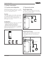
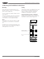
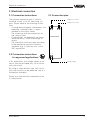
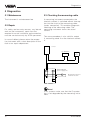
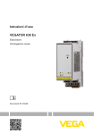
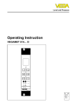
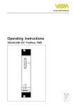
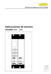
Level and Pressure
Operating Instructions
VEGASTAB 690
1
2
– +
3
4
7
8
2
1
on
VEGASTAB 690
5
9
6
10 11 12 13 14
in
out
Contents
Contents
Safety information ........................................................................ 2
Note Ex area ................................................................................ 2
1
Product description
1.1 Function and configuration .................................................. 3
1.2 Types and versions ............................................................. 3
1.3 Technical data ....................................................................... 4
1.4 Dimensions ........................................................................... 5
2
Mounting and installation instructions ................................ 6
3
Electrical connection
3.1 Connection instructions ....................................................... 7
3.2 Connection instructions for approved applications .......... 7
3.3 Connection plan ................................................................... 7
3.4 Connection examples .......................................................... 8
4
Setup
4.1 Indicating and adjustment elements .................................. 9
4.2 Setup sequence ................................................................... 9
5
Diagnostics
5.1 Maintenance ....................................................................... 10
5.2 Repair .................................................................................. 10
5.3 Checking the measuring cable ......................................... 10
Safety information
Note Ex area
Please read this manual carefully, and also take
note of country-specific installation standards
as well as all prevailing safety regulations and
accident prevention rules.
Please note the attached approval documents
(yellow binder) and especially the included
safety data sheet.
For safety and warranty reasons, any internal
work on the instruments, apart from that involved in normal installation and electrical connection, must be carried out only by qualified
VEGA personnel.
2
VEGASTAB 690
Product description
1 Product description
1.1 Function and configuration
1.2 Types and versions
VEGASTAB 690 power supply unit is a module instrument with plug-in socket, suitable for
carrier rail mounting DIN 46 277.
Standard application
A power supply unit powers max. two sensors. Both, i.e. power supply unit and sensor
form one measuring system.
Function
The power supply unit provides two galvanically separated supply circuits. Both circuits
are shortcircuit proof (current limitation
approx. 26 mA) and are equipped with interlock diodes for control.
e.g.
DCS
Configuration
VEGASTAB 690 power supply unit can power
- hydrostatic pressure transmitters
- process pressure transmitters or
- differential pressure transmitters
and ensures the configuration of a complete
measuring system per circuit in conjunction
with one of these sensors.
Standard application
1
2
3
– +
Application in Ex area
4
A power supply unit powers via max. two ia
safety barriers type 145 two sensors in Ex
area. Together they form one measuring
system.
2
1
on
VEGASTAB 690
5
9
6
7
Ex area
8
Non-Ex area
10 11 12 13 14
p
p
p
Safety barrier
type 145
VEGASTAB …
e.g.
DCS
Ex application
VEGASTAB 690
3
Product description
1.3 Technical data
Power supply
Operating voltage
Power consumption
Fuse
- supply range
20 … 250 V AC, 50/60 Hz
20 … 72 V DC
with backup power supply curve form
deviating considerably from mains sine:
Umax. = 125 V AC (rectangle)
max. 3 W (3 … 16 VA)
T 1 A, 250 V
Electrical connection
Screw terminal
max. 1.5 mm 2
Electrical protective measures
Protection
- instrument
- plug-in socket
Protection class
Overvoltage category
IP 30
IP 20
II
II
Ambient conditions
Permissible ambient temperature
Storage and transport temperature
-20°C … +60°C
-40°C … +70°C
Output
Output voltage
Current limitation
Load
- non-Ex circuit
- intrinsically safe circuit
Interlock diode
2 x 24 V DC floating
approx. 26 mA (shortcircuit proof)
max. 500 Ohm
max. 75 Ohm
(in conjunction with safety barrier type 145)
for output 1 and 2
max. instrument load 15 Ohm
Indicating elements
LED in front plate
green on: operating voltage on
Electrical separation measures
Reliable separation acc. to
VDE 0106, part 1 between
- reference voltage
- isolation resistance
power supply output 1 and output 2
250 V
3 kV
CE conformity
VEGASTAB 690 power supply unit meets the protective regulations of EMC (89/336/EWG)
and NSR (73/23/EWG). Conformity has been judged acc. to the following standards:
EMC
Emission
EN 50 081 - 1
Susceptibility
EN 50 082 - 2
NSR
EN 61 010
4
VEGASTAB 690
Product description
1.4 Dimensions
Carrier rail 35 x 7.5 or
35 x 15 acc. to EN 50 022
Transparent cover
2
3
4
7
8
54,5
118,5
1
on
5
9
134
VEGASTAB 690
6
10 11 12 13 14
36
5
Mounting and installation instructions
2 Mounting and installation instructions
Mounting
Coding
Each series 600 instrument consists of a
terminal socket for carrier rail mounting DIN
46 277 and a module unit.
The terminal socket is provided with pins and
the instrument with appropriate gaps (mechanical coding) to prevent inadvertent
swapping of the different instruments.
You can connect the supply voltage to terminals 9 and 10.
If there are adjoining series 600 instruments,
it is possible to continue the connection L1
and N directly via the supplied jumpers.
Instrument coding by means of differently
placed coded pins prevents inadvertent
swapping of the different signal conditioning
instruments and this power supply unit.
Note!
The jumpers must never be used for single
instruments or at the end of an instrument
row.
1
Disregard of this warning could lead to coming into contact with the operating voltage, or
could generate a short circuit.
2
3
4
Ao
VEGA
Bo
Co
1o
2o
3o
o
o
o
Instrument coding
VEGASTAB 690 (pin 5)
0¼10 V
DISBUS
7o
8o
9o
o
o
o
Direct connection for supply
voltage
5
9
6
6
N
L1
7
8
10 11 12 13 14
VEGASTAB 690
Electrical connection
3 Electrical connection
3.1 Connection instructions
3.3 Connection plan
The following connection plan is valid for
standard as well as for Ex measuring systems. Please observe the following instructions:
- If strong electromagnetic interferences are
expected, screened cable is recommended for the signal cables.
- The screening must be earthed only on
one (sensor) end.
- If overvoltages are expected, we recommend the use of VEGA overvoltage arresters.
- The connection must be made according
to the appropriate national installation
standards (e.g. in Germany acc. to the
VDE regulations).
3.2 Connection instructions
for approved applications
Output 1 for sensor 1
Output 2 for sensor 2
+ –
1
3
4
VEGASTAB 690
9
10
+ –
L1
In Ex applications, the voltage supply of the
sensor must be provided only via an intrinsically safe circuit.
2
+ –
N
Voltage supply
By using ia safety barriers type 145, intrinsically safe circuits can be prepared, see „3.4
Connection examples“.
Please also note the official document of the
ia safety barrier.
VEGASTAB 690
7
Electrical connection
Sensors in Ex area
3.4 Connection examples
Sensors in non-Ex area
e.g. hydrostatic pressure
transmitters or process
pressure transmitters
e.g. hydrostatic pressure
transmitters or process
pressure transmitters
1
+
1
+
2
–
e.g. VEGADIS
+
–
2
–
Ex area
e.g.
DCS
+
–
Non-Ex area
–
2
+
1
ia safety barrier
Load max. 500 Ohm
Type
145
e.g. VEGADIS
1
+
Meas. instrument
11 12
+ –
e.g. differential pressure
transmitter
e.g.
DCS
e.g.
DCS
+
2
–
+
–
+
–
–
+
–
Load max. 75 Ohm
Load max. 500 Ohm
+ –
1
2
+ –
3
4
e.g. differential pressure
transmitter
VEGASTAB 690
power supply unit
1
+
2
–
Ex area
Non-Ex area
ia safety barrier
–
2
+
1
Meas. instrument
Type
145
Mixed applications can also be connected to
the two outputs of the power supply unit, e.g.
- output 1, sensor in non-Ex area
- output 2, sensor in Ex area.
e.g.
DCS
11 12
+ –
+
–
+
–
Load max. 75 Ohm
+ –
1
8
2
+ –
3
VEGASTAB 690
power supply unit
4
VEGASTAB 690
Setup
4 Setup
4.1 Indicating and adjustment elements
2
1
2
3
4
3
± +
1
2
4
1
5
4.2 Setup sequence
The following listing shows the main setup
steps
- mount the terminal socket
- wire the socket acc. to your requirements
- cover the input terminals with the separating wall (2)
- mount the module unit to the terminal
socket
- switch on the supply voltage, the green
LED (1) lights
on
VEGASTAB 690
5
6
7
8
6
9
1
2
3
4
5
6
10 11 12 13 14
LED secondary voltage available
Separating wall
Terminals output 1 and 2
Interlock connection sockets output 2
Interlock connection sockets output 1
Terminals supply
VEGASTAB 690
9
Diagnostics
5 Diagnostics
5.1 Maintenance
5.3 Checking the measuring cable
The instrument is maintenance-free.
A measuring instrument connected to the
interlock sockets is switched without interruption into the circuit of the measuring cable
(series connection). This enables diagnostic
checking of the measuring cable. The
measuring instrument shows the actual
current.
5.2 Repair
For safety and warranty reasons, any internal
work on the instruments, apart from that
required in normal installation and connection,
must be carried out only by VEGA personnel.
In case of defect, please return the respective instrument with a short description of the
fault to our repair department.
The same procedure is also valid for output
2, measuring cable 2 on the interlock sockets
2.
Sensor
e.g. VEGADIS
e.g.
DCS
2
–
1
+
+
+ –
+ –
1
3
2
–
+
–
VEGASTAB 690
power supply unit
4
mA
1
Measuring instrument
load max. 15 Ohm
2
Note!
In Ex systems make sure that the Ex protection is not degraded by the measuring instrument.
10
VEGASTAB 690
Notes
VEGASTAB 690
11
VEGA Grieshaber KG
Am Hohenstein 113
D-77761 Schiltach
Phone (0 78 36) 50 - 0
Fax (0 78 36) 50 - 201
E-Mail [email protected]
www.vega.com
ISO 9001
The statements on types, application, use and operating conditions of
the sensors and processing systems correspond to the latest information at the time of printing.
Technical data subject to alterations
19959-EN-000701