1
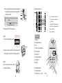
FLOW-S
Series Ultr
asonic Water Meter
Series Household-Use Version
S Series Industrial Version
Installation & Operating Instructions
Add: Qinghua Road, New and Hi-Tech Development Zone,
Tangshan, Hebei Province, China
Marketing Hotline: +86-0-315-3208501 3208502 3208503
Service line after sale: +86-0-315-3208508
Fax: +86-0-315-3190081
Postcode: 063020
E-mail: [email protected]
http://www.hzyb.com
[email protected]
Subject to change without notice
2005/05/06
Tangshan Huizhong Instrumentation Co., Ltd
420mA output (including cumulative pulse output)
`ìãìä~íáîÉ=éìäëÉ
To our dear user:
Thanks for your selection for use of our FLOW-S series
ultrasonic water meter. The battery-powered water
meter with a high sensitivity to minimal flowrate and a
high measuring accuracy, and capable of performing
wireless transmission of meter reading can help you
eliminate the discrepancy between the water supply
volume and its sales volume and enhance your water
meterage management level. Sailsors Instruments
Ltd., Beijing is ready to provide you superior-
M-BUS output
US
quality products and first-rate service
21
Appendix 1 Grounding
=1. General Description
1. The need for meter grounding depends on the degree
of electrical interference on site. If the interference is
so severe as to affect the normal operation of the meter,
the grounding is required. In general cases, there is no
such need.
2. The ground conductor line must not be connected with
other electrical equipment for avoiding the conduction
of any interference voltage.
Appendix 2 Dimensions of various terminal blocks, mm
(Provided to the user according to the type of the meter selected)
RS485 output
20
Operating on velocity-difference principle, the FLOW-S series ultrasonic water meter is
specifically designed for urban water supply pipeline network and residential buildings. The
conventional water meters suffer from the drawbacks that they are only operable at a higher
initial flowrate and are insensitive to a small flowrate. However, the FLOW-S series meter can
help tackle the bottleneck. And the meter is also highly adaptable to diversified industrial
conditions.
Due to the use of ultrasonic flow transducer, it has no mechanical moving parts, and is high
in reliability, less in maintenance requirement and immune to magnetic interference.
Highly sensitive to minimal initial flowrate and high in measuring accuracy. The use of the
meter entails no pressure loss in pipe, and its maximum range ratio is 200:1.
Extremely low in power consumption. Capable of working continuously for a period of over
6 or 10 years with a built-in battery cell.
Capable of performing various output functions.
Single-channel, double-channel and 4-channel options are available for selection.
Three design versions are available, i. e. the ordinary, 2-way and anti-theft versions to cater
to the different needs of users.
The 2-way version (its model is the same as that of an ordinary version yet with a suffix D)
can measure water flow and record cumulative running time in either positive or reverse flow
direction.
1
The use of the anti-theft version (indicated by a suffix A) can prevent anyone from gaining
advantage by trickery in the use of water because the cumulative water flowrate measured by
the meter is a cumulative total of the absolute instantaneous flowrate values in both the positive
and reverse directions.
All the technical data in this instructions refer to the ordinary version and are also applicable for
both 2-way and anti-theft versions.
The different versions of water meters are in conformity with the THIC enterprise standard Q/
THY001-2004.
FLOW-S series ultrasonic water meter is composed of the pipe section-mounted transducer and
a conversion unit. For the industrial water meter, 3 different types of transducers are available
for selection, i.e. the single-channel, double-channel and 4-channel versions.
FLOW-SH series household-use ultrasonic water meter is in an integral form while the FLOW-S
industrial type has 3 different versions out of which two are in integral form (Viewed from
the top or the side) and one is in non-integral form.
Integral Version
FLOA-SH Household-Use Version DN15-DN25
FLOW-SD-x-C Industrial Version (Side View) DN50-DN250
FLOW-SD-0-D Industrial Version (Top View) DN15-DN40
FLOW-SD-x-D Industrial Version (Top View) DN50-DN250
ô
2
C. Record the meter’s instantaneous flowrate readings at fixed time interval. The readings should
be taken continuously at least 20 times, and the minimum time duration for making a calibration
each time is no less than 2 minutes.
D. Record the calibration system’s standard flowrate qsi.
kçíÉWqÜÉ=Å~äáÄê~íáçå=ãìëí=ÄÉ=ã~ÇÉ
Ä~ëÉÇ=çå=áåëí~åí~åÉçìë=Ñäçïê~íÉK
E. Calculate the mean instantaneous flowrate value qi.
Error computation
Ei=
qi-qsi
qsi
100%
The error of the ith flowrate point
qi - The mean instantaneous flowrate displayed by the meter.
qsi - The standard flowrate value of the ith point
qs - Standard flowrate
At qmin =qs < qt, E===2.0%
At qt =qs =qmax, E ==1.0%
Where:
qmin — The minimum flowrate
qt — The boundary flowrate
qmax— The maximum flowrate
For the correction of meter coefficient, refer to the section on Setting of Parameters.
19
8. Calibration Method
ô
FLOW-SD-x-E Industrial Version
DN15-DN250
The FLOW-S series ultrasonic water meter can realize wireless transmission of meter readings via the GSM public network (For details, refer to the FLOW-SD/GSM Meter Reading
Wireless Transmission Unit Operating Instructions.
Non-Integral Version
===The ultrasonic flowmeter is in conformity with the THIC standardUltrasonic Water Meter
Q/THY001-2004.
===According to the calibration requirement, a standard calibration system should meet the
following requirements:
A. The system should have an effective calibration certificate.
B. The accuracy of the system must not exceed 1/3 of the basic error allowance of the water
meter under calibration.
C. According to the THIC standardUltrasonic Water MeterQ/THY001-2004, the system
should have the required condition for the mounting of the water meter to be calibrated.
D. The system should have the following water flow conditions: a full-pipe unidirectional
steady flow with a content of suspended matters less than 10g/l and a particle size of less
than 1mm and without any entrained air.
Requirements on water meter mounting conditions
A. The water meter should be concentrically aligned with the pipe, and the sealing gasket is not
allowed to protrude into the pipe.
B. The water meter should be mounted in the same direction as that of the water flow.
Calibration procedure
A. Upon completion of the mounting of the meter, start the calibration system to run for 10
minutes for flow stabilization and thorough evacuation of air.
B. Select the flowrate points at the meter’s screen display of instantaneous flowrate and start
the calibration work after the flowrate is in a steady state.
18
2. Flowrate Measuring Range
Pipe ID
EããF
15
20
25
32
40
50
65
80
NMM
NOR
NRM
OMM
ORM
Note:
S-C*
D-C**
S-C
D-C
S-C
D-C
S-C
D-C
S-C
D-C
4-C***
S-C
D-C
4-C
Start-up
Flowrate
0.0019
0.0019
0.0045
0.0073
0.0114
0.0353
0.06
MKMV
MKMSP
MKNQN
MKMVV
MKOON
MKNRR
MKPNU
MKOOP
MKRSR
MKPVS
MKOOS
MKUUP
MKSNU
MKPRP
Cumulative Flowrate
Min. Flowrate Boundary Flowrate Max.=Flowrate
èãáå
èã~ñ
èí
(m3)
P
Min. Reading
Max.
Reading
(m3/h)
(m/s)
Eã LÜFEãL
0.0238
0.0238
0.056
0.092
0.144
0.35
0.60
MKV
MKV
NKQN
NKQN
OKON
OKON
PKNU
PKNU
RKS
RKS
RKS
UKUP
UKUP
UKUP
ëF
0.072
0.072
0.169
0.275
0.429
2.1
3.58
RKQP
RKQP
UKQU
UKQU
NPKOR
NPKOR
NVKMU
NVKMU
PPKVP
PPKVP
PPKVP
RPKM
RPKM
RPKM
1.5
2.5
3.0
12
20
50
80
NPM
NPM
OMM
OMM
OSM
OSM
POM
POM
ROM
ROM
ROM
SMM
SMM
SMM
99999.999
9999999.9
* S-C - Single-channel version ** D-C - Double-channel version *** 4-C - 4-channel version
3
0.001
0.1
6. Replacement of Battery
3. Main Technical Data
Item
Fluids Measured
Accuracy, %
Pipe Size Range, mm
FLOW-SH Household-use VersionSFLOW-SD-1 l Version [Single-channel]
DN15DN25
DN15DN250
Max. pressure-bearing
capacity of pipe section
Working Conversion unit
environ- Transducer
ment
Cable
Output Signal
FLOW-S-2(4) Industrial Version [2/4-channel]
Full pipe flow of water, sewage and other homogenous fluids with a content of suspended matters not exceeding 10g/l and a particle size of less than 1mm.
1.0
1.0
0.5
Double-channel: DN80-DN250 4-channel: DN200-DN250
1.6MPa
Temperature: -10+45Humidity: 85% (RH) (For use under otherwise specific conditions, please specify on ordering.)
Normal-temperature model: 50I=High-temperature model: 100
RS485
4-20mA (External power required - DC24V), Cumulative pulse (Cycle - 12m/s Pulse width -
M-BUS
6ms 0.1m3/pulse RS485 M-BUS and GSM/GPRS wireless transmission of meter readings
Magnetic induction key or push button
8-digit LCD + prompting character Word height:8.5mm Resolution:= DN40mm:0.1L/H; >DN40mm:1L/H
Display
Data Storage
Instantaneous flowrate (m3/h) Cumulative flowrate (m3) Cumulative effective running time (h) Date (yy/mm/dd) Clock (hh/mm/ss)
Cumulative flowrate and cumulative effective running time (Data can be saved in EEPROM for 100 years after power fail.)
Capable of operating continuously with one built-in battery for a period of > 10 years (Domestic version) and > 6years (Industrial version)
IP54
Protection Class
Power Consumption
7. Self-diagnostic Function
-40+65
Keyboard
Display Mode
Operating Power Source
====The water meter operates with a 3.6V lithium battery which has a service life of over 6 years
at an ambient temperature of 0~35°C. When the symbol “ ” is displayed, it indicates that the
battery is at low voltage and needs to be replaced.
Note: The battery replacement should be made by professional personnel. After battery
replacement, the stored “cumulative flowrate” and “cumulative running time” can not get lost (If
new batteries are needed, please contact our company).
Integral version D type (Viewed from the top): IP68 Integral version C type (Viewed from the side): IP65
Conversion unit of non-integral version:IP68 Display of non-integral version: IP65
Diagnostic Prompt
“ERR” keeps on display
Frequent display of “ERR”
Display of “
4
Remedial Measures
Replacement
”===============Low battery
Display of
<0.8mW
Transducer-conversion unit connecting cable for non-integral model: standard length 6m.For non-standard cable length, please specify on ordering.
Prompt Information
1. Empty pipe
1. Let the pipe to have full flow
2. Conversion unit surface severely fouled with scale deposit 2. Clear off the scale deposit
3. Faulty meter
3. Contact our company for maintenance
Remove them
Too much air bubbles or impurities in water
An indication of the low voltage value and the meter Replacement
ceases to work for inadequate power. Yet in this case,
the stored data can still be retrieved.
Display of “88888888”
Faulty EEPROM
Please note down the current “cumulative flowrate” and “cumulative running time”, and immediately contact
our company for repair
Display of “44444444”
(E type)
Transducer-conversion unit connection cable broken
or not correctly connected. RS485 communication
error
Check for correct connection.
17
(3) Place a seal washer between each pair of mating flanges (meter
flange and pipe flange) and then fasten them up with bolts
after alignment is made.
Performance-Deviation Curve
Seal Washer
qmin1 - Min. flowrate (multi- channel model)
qmin2 - Min. flowrate (single- channel model)
qmax - Max. flowrate
qt1 - Boundary flowrate (multi- channel model)
qt2 - Boundary flowrate (single- channel model)
Dark grey: Single-channel
Light grey: Multi-channel
Caution: (1) The connection should be tightly sealed for avoiding
water leakage.
(2) The arrow
on the meter should point to the same
direction as that of the water flow.
III. Mounting of FLOW-SD-E conversion unit
4. Operation
Method 1
1. Fix the slide rail horizontally on the wall.
Stop piece
2. Hang the conversion unit on the slide rail. Then push upward the
plastic stop piece to enable the unit to firmly grip onto the rail.
137
Method 2
Fix the conversion unit with screws according
to the method as illustrated.
8
19
16
Front Panel
(A) - Magnetic induction key
(B) - Unit
(C )- Battery low voltage indication
(D) - Error indication
(E) - Magnetic rod
(F) - Magnetic induction key
(G) - Display item
(H) - Display
^
_
`
e
d
IF - Instantaneous flowrate
CF - Cumulative flowrate
CT - Cumulative time D - Date
a
c
C - Clock
b
5
Note:
Method 2 Using the connecting elements
1. This is the front panel of the 2-way water meter. For the ordinary and anti-theft meters, there are no negative cumulative flowrate
and running time display items.
2. The front panels of the C and D versions are all provided with glass protective covers. This type of front panel is operated with a
magnetic induction key. When the induction key is pointed by a magnetic rod in a vertical position, 8 black inverted triangles
are displayed. This indi cates that the meter enters the effective operation mode.
3. If the magnetic induction key is pushed manually, the 8 inverted triangles will also appear to show that the meter is in normal
operation mode.
====Operation and Display of the Integral Version
I. Display operation
Each time when “ ” is pressed, the meter will
make a cyclic display of the following items:
(1) Cut the pipe apart to provide the space for
mounting the meter and connecting elements.
(2) Screw a connecting element onto each end
of the pipe.
(3) Align the meter with the connecting element
and then tighten them.
fc `c
+
Instantaneous flowrate, m3/h
`c `q `q a
`
- + -
Note: Either positive or negative instantaneous flowrate is displayed, depending on
the direction of water flow.
Direction of
water flow
Caution: (1) The connection should be tightly sealed for
avoiding water leakage.
(2) The arrow
on the meter should point to the
same direction as that of the water flow.
II. Flange connection
Cumulative flowrate, m3
fc `c
+
Note:At the time when either instantaneous
`c `q `q a
`
- + -
flowrate or cumulative flowrate is on display,
the display will stay on the screen if no other key operation is made. If the screen changes to other display and no further key
pushing is made within 10 minutes, the screen will return automatically to cumulative flowrate display. For a 2-way version
water meter, if the cumulative flowrate is on long time display, the screen will display the positive cumulative flowrate 8 times
and the negative cumulative flowrate 8 times alternately.
6
==(1) Cut the pipe apart to provide the space for
mounting the meter
(2) Weld a flange onto each end of the pipe.
15
Overall dimensions of GSM
Negative cumulative flowrate,m 3(2-way version only)
fc `c
+
`c `q `q a
`
- + -
Cumulative effective running time, h
Note:When “ERR” is displayed, it indicates that
fc `c
there is no water in pipe or the water flow contains too much air bubbles. In this case, the cumulative running time stops adding up.
+
`c
`q `q a
`
- + -
Mounting method
fK Thread connection
Method 1Without the use of connecting elements
(1) Cut apart the water supply pipe at the mounting
point to provide the space for accommodating
the meter.
(2) Align the meter concentrically with the pipe.
Connect the pipe union with the meter’s thread
joint and then tighten them with a spanner.
Caution: (1) The connection should be tightly sealed for avoiding
water leakage.
(2) The arrow
on the meter should point to the same
direction as that of the water flow.
14
Negative cumulative effective running time,h
(2-way version only)
fc `c
+
fc `c
Direction of
water flow
+
a~íÉWvLjLa
`äçÅâWeêKLjáåKLpÉÅK
fc `c
+
7
`c
`q `q a
`
- + -
`c
`q `q a
`
- + -
`c
`q `q
- + -
a
`
Non-integral version
II Setting of Parameters
Keep
key depressed for 3J9 seconds,the
meter will enter the effective operation mode after
the 8“
”symbols appear. For setting each
parameter,the abovementioned procedure should
be repeated to show this display.For the setting of
each the following parameters,the display of the 8
“ ”symbols is omitted.
fc `c
+
Note:1.“
” indicates the item on display
2.“
” is a key for setting of parameters
3.“
” Pressing this key to enter the next
screen display.
fc `c
+
`c `q `q
a
`
a
`
- + -
`c `q `q
SCL-61Dx-E Industrial Version DN15-DN250
- + -
Mounting Dimensions of Flange-Connected Integral & Non-Integral Versions
(Including multi-channel, without mating flange)
Overall Dimensions, mm
Damping coefficient,range 120
Set the 420mA maximum output value 101100(m3/h)
Note:This setting shoudl be made based on the actual
measuring range of the meter used.
fc `c
`c `q `q
+
- + -
fc `c
+
a
`
`c `q `q a
`
- + -
DN
50
65
S-C*
80
D-C*
100
125
150
200
200
D
165
185
200
200
220
250
285
340
340
D1
125
145
160
160
180
210
240
295
295
D2
99
118
132
132
156
184
211
266
266
f
3
3
3
3
3
3
3
3
3
b
20
20
22
22
24
22
26
26
30
d= n
L
L1
19 4
200
19 4
200
19 8 200/225
250
19 8
213
19 8
250
19 8
250
23 8
300
23 8
350
23 12
350
8
fc `c
`c `q `q
+
- + -
a `
H2
244
261
277
277
296
324
354
412
412
H3
238
255
271
271
290
318
348
406
406
H4
Wt. Pressure
Remarks
(kg) (MPa)
7.4
8.9
10.5/10.7
10.5/10.7
185 13.2
16.8
21.9
37.3
d— Diameter of flange
1.6 connection
bore.
n— Number
of flange
1.0 connection
1.6 bores.
D1— Center
1.0 diameter of
1.6 flange connection bore
38.1
63
405
355
319
3
32 28 12
400
531 471 465
Notes: * S-C - Single-channel version
D-C - Double-channel version
1. The flange size conforms to the standard GB/T 17241.6-1998.
2. The L figures in the Table conform to the specifications as specified in the national standards on all cold water meters excepting
the volumetric type single- and multi-bundle flow water meters. For other L values to suit your specific needs, please specify on ordering.
250
Date:Y/M/D
H1
304
321
337
337
356
384
414
472
472
13
5. Overall Dimensions and Mounting Method
Overall dimensions (mm)
Clock:hr./min./sec.
Integral Version
+
- + `q
-
fc `c
a
`c `q
`
Note:For the setting of the following parameters,the entry of a secret
code is required.
e
i
FLOW-SH Household-Use Version
DN15DN25
p`iJSNañ `=Industrial Version
(Side View)
akRMakORM
FLOW-Sp`iJSNaNJa=Industrial Version (Top View)
akNRakQM
Overall Dimensions (mm) of the SCL-61H and
FLOW-SD1-D Versions (DN15-DN40mm)
DN
p`iJSNañJa=Industrial Version (Top View)
akRMakORM
L
L1
H
Connecting Thread
Clearing of positive/negative cumulative
effective running time,h
+
Clearing of positive/negative cumulative
flowrate,m3
Note: When “ERR” is displayed, it indicates that
there is no water in pipe or the water flow contains
too much air bubbles. In this case, the cumulative
running time stops adding up.
Setting meter coefficient: 80129.9
- + `q
-
a
`
fc `c
`c `q
fc `c
+
-`c +
`q `q
+
- + `c
`q `q
a
`
`c
`q `q
a
`
fc `c
a
`
W/Connecting Fittings W/O Connecting Fittings
15
110
146
125
20
130
155
125
dNLO”
dPLQ”
25
130
155
125
dPLQ”
32
230
160
40
245
210
dPLQ”
dN”
dN”
dNNLO”
Baud rate selectable:9600,4800,2400,1200
fc `c
+
dO”
12
9
- + -
Setting the meter’s account number: 65165
Store and clear the zero-point flowrate valie
The setting is completed, and the screen returns
to cumulative flowrate display.
fc `c
`c
+
a
`q `q
Non-integral version (Operated with manual key)
I. For the display, refer to the corresponding display items as described in the previous section
for the integral version.
II. Setting of parameters
For the setting procedures, the steps (1) ~ (8) are the same as those in the case when an integral
meter version is used.
Zero-point setting
fc `c
+
fc `c
`c
+
`
a
`q `q
`
- + -
- + -
`c
`q `q
-
+ -
a
Note:1. If at the time when the “
” key is kept depressed with the magnetic rod, the numbers of “2” ~ “8” are repeatedly
displayed in cycles, accompanied at the same time by a display of 7 “2”s at the right side. It indicates a communication
failure (failure of setting of parameters).
2. If the abovementioned cyclic display procedure is interrupted and a certain display maintains on the screen for a period of
over 60 minutes, the screen will automatically go back to display of cumulative flowrate.
13 Clear
the stored zero-point flowrate value
`
fc `c
+
`c
a
`q `q
`
- + -
The setting can be made by selecting one of the following different modes (0,1,2,3).
14 Setting
Minimal flowrate value cut-off enabled
Note:This function is used to cut off the flow ve-
fc
locity values in a range of 0.002 m/s-0.005 m/s
`c
`c
`q `q
+
-
+ -
Minimal flowrate value cut-off disabled
fc `c
+
`c
`q `q
a
of meter’s account number:65165
The setting is completed, and the screen returns to cumulative flowrate display.
`
`q `q
`c
+
a
`
- + -
Indication of signal intensity
a
`
If the key is kept depressed for over 10 seconds,
there will be an indication of the signal intensity
(0.00-1.50).The highest intensity is 1.50.At an
intensity of <0.15, “Err” will be displayed,and
the meter stops working.
- + -
Clicking the
key to return to the screen of
cumulative flowrate display.
10
fc `c
fc `c
+
`c
`q `q
a
`
- + -
Note:If within 3 minutes, no further key pushing is made, the screen
will automatically go back to display of cumulative flowrate.
11