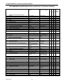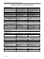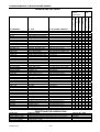
1
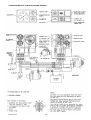
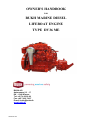
OWNER'S HANDBOOK
FOR
BUKH MARINE DIESEL
LIFEBOAT ENGINE
TYPE DV36 ME
BUKH A/S
Aabenraavej 13 - 17
DK - 6340 Krusaa
Tel: +45 74 62 20 88
Fax: +45 74 62 74 07
E-mail: [email protected]
www.bukh.dk
009W0327-R03
OPERATING MANUAL FOR BUKH DV36ME ENGINES
CONTENTS
Page
Pictures for recognition of engine ................................................ 3
Introduction .................................................................................. 4
Standard equipment ..................................................................... 4
Operating manual......................................................................... 4
Preparation for the first start......................................................... 5
Before start ................................................................................... 5
Electric start ................................................................................. 5
Hand start ..................................................................................... 5
After start…………………………………………………….…… ..... 6
Maneuvering ................................................................................ 6
Stopping the engine ..................................................................... 6
Running in .................................................................................... 6
Maintenance ................................................................................. 6
Belt for alternator .......................................................................... 6
Air inlet filter ................................................................................. 6
Fuel filter....................................................................................... 6
Fuel lift pump ................................................................................ 7
Lubricating oil system................................................................... 7
Change of oil ................................................................................ 7
Recommended lubricating oil ...................................................... 7
Change of lubricating oil filter ....................................................... 7
Cooling water system ................................................................... 7
Seawater cooling .......................................................................... 7
Exchange of zinc anode ............................................................... 7
Exchange of impeller.................................................................... 7
Freshwater cooling ....................................................................... 8
Frost precautions ......................................................................... 8
Electrical system .......................................................................... 8
Marine gear .................................................................................. 8
Propeller equipment ..................................................................... 9
Sail drive....................................................................................... 9
Galvanic corrosion ..................................................................... .10
Starting instructions.................................................................... .10
Winter storage of the engine ...................................................... .11
Technical data for engine and gearbox...................................... .12
Recommended maintenance and checklist ............................... .13
Irregular operation ...................................................................... .14
Lubricating oil chart .................................................................... .15
El-diagram .................................................................................. .16
DV36 installation.. ....................................................................... 17
List of representatives ................................................................. 18
General Terms of Sale and Delivery .......................................... .22
009W0327-R03
-2-
OPERATING MANUAL FOR BUKH DV36ME ENGINES
1.
2.
3.
4.
5.
6.
7.
8.
9.
10.
11.
12.
13.
14.
15.
16.
17.
18.
19.
20.
21.
22.
23.
24.
25.
26.
27.
28.
29.
30.
31.
32.
33.
34.
35.
36.
37.
38.
39.
40.
41.
Lubricating oil filling plug
Valve cover
Electric stop solenoid
Air filter with noise suppression
Fuel filter
Cooling water drain plug
Dipstick for engine oil
Oil pressure switch
Lubricating oil filter
Fuel pump
Control lever
Cock
Reversing lever for gear
Bracket for reversing cable
Coupling flange for propeller shaft
Reverse-reduction gear
Housing for vacuum valve
Bilge pump for change of lub. oil
Bracket for control cable
Electric multi plug
Fuel lift pump
Lifting fittings
Water cooled exhaust manifold
Zinc anode
Cooling water expansion tank
Cooling water filling plug
Identification label
Water drain plug for exhaust manifold
Thermostat housing
Cooling water temperature transmitter
Exhaust
Outlet to keelcooler
Circulation pump
Dip stick for gear oil
Reversible engine mountings
Lubricating oil cooler
Electric starter
Inlet from keel cooler
Flywheel
Tension device for V-belt
Alternator
009W0327-R03
-3-
OPERATING MANUAL FOR BUKH DV36ME ENGINES
INTRODUCTION
BASIC ENGINE CONFIGURATION:
The BUKH Marine Diesel engine is a four-stroke marine diesel engine with direct fuel injection and the following basic
equipment:
Crankcase with oil pan, one-piece cylinder head with 2 valves per cylinder, forged crankshaft with counterweights, balance
weights, cast iron connecting rods, light metal pistons, water-cooled exhaust manifold; all necessary pipework for exhaust,
coolant, fuel and lubricating oil are fitted on engine.
A reverse/reduction gearbox with integrated thrust bearing is fitted on the engine.
No BUKH Diesel Engine is sent from the factory without having been thoroughly tested.
The tests have shown that the engine in all aspects is working satisfactorily and is generating its full power.
You will expect the engine to work reliably witout giving any problems, and to achieve this you are asked to follow the
instructions in this manual. By so doing, you will get the best from your BUKH engine.
If a problem with the engine should arise, we ask you to apply to one of our distributors, who will always be ready to
help you, having skilled personnel, necessary tools etc., and at the same time you will be sure that only original BUKH spare
parts are used.
Do always use original BUKH spare parts.
When ordering spare parts from the distributor please state:
Engine type and serial number, description and number of parts.
BUKH A/S
Powering Marine Safety
As BUKH A/S is always endeavouring to improve the engines, the specifications mentioned are subject to alterations
without previous notice.
Read this instruction book thoroughly before starting your new BUKH Diesel Engine.
STANDARD EQUIPMENT for DV36ME
Reverse-reduction gear
Decompression lever
Wet sump lubrication oil system
Full-flow lubrication oil filter
Automatic injection timing
Centrifugal governor
Watercooled exhaust manifold
Air inlet filter and silencer
Fuel lift pump
Electric start
Charging alternator
Operating remote panel with:
a) Charging light
b) Lub. oil pressure warning light
c) Cooling water temp. warning light
d) Key switch for start and stop
e) Audible warning
Fittings for remote control
Standard set of tools
Drain pump for lub. oil (built on engine)
Following documentation is delivered with the engine:
1. Operating manual with sparepart katalog
2. Test certificate
Flex. engine mounts (optional)
Stern gear (optional)
Raised hand start (optional)
OPERATING MANUAL
Before the engine is put into use you are recommended to get familiar with the placing of the following components of
engine and gear:
Fuel oil filter, lub oil filter and air intake filter, fuel lift pump with handle, zincrod in the crankcase and water-separator in the
fuel pipe (if mounted).
Where is lub oil poured into engine and gear and where are the dipsticks placed? Where is fuel oil filled into the fuel tank
and where is the drain plug placed? Where is the main switch?
009W0327-R03
-4-
OPERATING MANUAL FOR BUKH DV36ME ENGINES
Preparation before first start
1.
2.
3.
4.
5.
6.
Pour lubricating oil through filling hole on top of valve cover.
Check that oil level is between the marks on the dipstick, placed at
the port side of the engine.
Check oil level as mentioned below:
a) remove and wipe dipstick
b) reinsert dipstick in the pipe
c) withdraw dipstick, check oil level.
Pour lubricating oil through dipstick hole on the top of reverse- and reduction gear
and check oil level as described in pos 1.
Flexible sterntube: Lubricate the stuffing box with sterntube oil (outboard).
Unscrew the filler plug and pour in oil until the bearing is full.
Important:The stuffing box shall under no circumstances be force-lubricated.
These instructions are only valid for propeller equipment supplied by BUKH.
If other equipment is mounted, we refer to the instructions given
for this.
We always recommend checking of oil level before start.
Fill the fuel tank.
Bleed the fuel system in the following way:
a) Loosen the slotted screw B on the fuel filter and pump with the handle A on
the fuel lift pump until the fuel is free from air bubbles and runs out at the
slotted screw.
b) Tighten the slotted screw B and continue pumping with the handle A until
fuel, free from bubbles, runs through the transperent hose from fuel pump to
tank.
You must lock the pumping handle in the upper position when you
have finished pumping.
c) Loosen the fuel pressure pipes at their connection on the fuel valves and turn the engine by the starter motor until
fuel, free from bubbles, runs out from the fuel pressure pipes. Finally
tighten the pipes and the engine fuel system is ready for use.
Normally it will not be necessary to bleed the fuel system before starting but
after changing the fuel filter element or carrying out any work on the fuel system
it should be bled in the following way: Loosen the bleed screw and operate the
hand priming lever on the fuel lift pump until air-free fuel discharges from screw.
Tighten bleed screw. Loosen high pressure pipe unions to injectors and turn
engine until fuel discharges from pipes. Reconnect pipes to injectors. The
engine will start in the normal way.
AFTER THE ENGINE HAS BEEN TAKEN INTO USE
Before start
1. The oil level of the engine should be checked every 14 days or every 25
hours of running as described in ”Preparation before first start”. It is not
necessary to refill oil if the level is between the two marks on the dipstick.
2. The oil level of the reduction gear should be checked every 14 days or every 25
hours of running as described in ”Preparation before first start”.
3. The sterntube stuffing box should be lubricated every 14 days or every 25
hours of running.
4. Check the quantity of fuel in the tank.
Electric start with remote control and instrument panel
1. Switch on the main switch.
2. Put the marine gear in neutral position by means of the control handle.
3. The engine is started by pushing the key and turning it to the right.
The starter should not work for more than 10-15 secs. continuously.
Hand start (optional)
1. Put the gear lever in neutral position.
2. Turn decompression lever on valve cover anti-clockwise as far as possible.
3. Engage starting handle and crank engine as quickly as possible. Release decompression lever quickly by turning lever clockwise while cranking and engine will start.
4. By hand start in cold weather you may achieve an easier start after having cranked
the engine with activated decompression lever before the starting procedure.
Never accelerate a cold engine. Let it get warm first.
009W0327-R03
-5-
OPERATING MANUAL FOR BUKH DV36ME ENGINES
After Start
1. When the engine has started, the RPM should be 900-1000 RPM when idling.
2. Check the oil pressure. Normally this should be 2-4.5 bar. With cold engine the RPM should be kept down so that the oil
pressure does not exceed 4.5 bar. When idling at warm engine the oil pressure must not be below 1 bar.
3. Immediately after start the oil pressure warning lamp should go out. During normal operation the lamp should stay off.
4. Make sure that the charging control lamp goes out after the engine has started.
5. Check the cooling water temperature frequently. The temperature should be in the area of 70 – 95oC when engine is
warm.
Manoeuvering
1. With the control lever in central position the engine is idling, and the
marine gear is in neutral (pos. 0). When the lever is moved forward in
range 1, the marine gear is engaged to "Ahead” first, and then in
range 2 the engine R.P.M. is increased. When the lever is moved from
the central position to range 3, the marine gear is engaged to "Astern”
first, and then in range 4 the engine R.P.M. is increased.
2. Only engage "Ahead” or "Astern” when the engine is idling.
3. To accelerate engine without engaging gear, operate gear release
button 5 and move control handle in either direction.
4. Increase the load gradually from idling in the course of the first 15-20
minutes shortly after the start of the engine.
Stopping the engine
1. Reduce the load gradually in the course of 15-20 minutes before stop.
2. Reduce the engine to idling and put the gear in neutral position.
3. Turn the ignition key left to stop position, pushing it slightly inwards.
The key must not be left in this position after the engine has stopped
due to the large current consumption of the stop solonoid. In this
position the acoustic alarm will function, when the engine has
stopped.
4. Turn off the battery main switch.
Running in
To secure long life and maximum power it is recommended to run the
engine for the first 25 hours at not more than 80 pct. of the maximum
output (about 3200 r.p.m.)
You should avoid slow hauling as for instance towage. After the first 25
hours it is recommended to change engine and gear oil and to tighten
up the cylinder head and to check or to possibly adjust the tension of the
V-belt. Besides, it is recommended to let an authorized service dealer go
over engine and installation.
MAINTENANCE
Belt for alternator
To be adjusted every 150 hours by turning the alternator round the centres of
suspension. Tensioning should be so as to allow 8 - 10 mm deflection of the belt
under firm thumb pressure.
Air inlet filter
This is a wire gauze filter to be rinsed in petrol and cleaned by a blast of
compressed air after 300 hours' operating.
Fuel filter
A fuel filter is fitted between the fuel lift pump and the H.P. fuel pump. The filter is a
disposable one which cannot be cleaned. It should be changed every 300 operating
hours or if water contamination is suspected.
Change the filter as follows:
1. Drain off the fuel from the filter by slackening drain screw A in the bottom of the
filter casing B.
2. Remove by hand or by means of a pair of tongs the filter casing and discard it.
3. Clean the sealing surface of the filter holder C if necessary.
4. Fill the new filter casing with clean fuel through the holes at the top of same.
5. Screw on the filter casing and tighten it by hand about half a turn after the gasket
fits tightly.
6. After changing the filter, bleed the fuel system as stated under ”Preparation for
first start”
009W0327-R03
-6-
OPERATING MANUAL FOR BUKH DV36ME ENGINES
Fuel lift pump
The fuel lift pump is a cam shaft driven sealed type diaphragm pump, which cannot be
dismantled for repair or cleaning. It is recommended to install a water/dirt accumulating
filter in the suction line to the pump.
After repairs the fuel system must be bled as described under ”Preparation for the first
start” if necessary.
Lubricating Oil System
The engine is pressure lubricated and the oil system has a built-in relief valve for
controlling the oil pressure. A lubricating oil cooler is also fitted.
The oil level is checked as mentioned before.
Change of Oil
Lubricating oil should be changed for the first time after 25 hours of running,
later for every 150 hours or at least once a year. It is recommended to change the oil when engine is warm, and the procedure is as follows:
1. Turn the left cock below oil bilge pump 90°.
2. Pump up the oil from the sump by means of the bilge pump.
3. When the sump is empty pour fresh oil.
4. Check oil level on dipstick.
Recommended Lubricating Oil
Modern diesel engines demand heavy-duty oils with additives securing best
operation conditions and longest life time of the engine under various conditions.
Therefore use a first class HD-oil from a recognized oil company.
Oil specifications as mentioned in ”LUBRICATION OIL CHART”.
When operating under difficult conditions, i.e. frequent cold starting,
short operation periods, greatly varying loads, use quality ”Service
CD” and also use quality "Service CD" in case the sulphur content of
fuel is higher than 1 %.
Change of Lubricating Oil Filter
Lubricating oil filter cannot be cleaned, but should be changed every
150 hours or once a year. To change the filter proceed as follows :
1. Unscrew filter A and discard it.
2. Clean the sealing surface of the engine B, and remove old
gasket C if any from old filter
3. Mount new filter at once under clean conditions.
4. Screw on filter until gasket fits tightly, tighten a further half turn.
5. Fill with oil until normal level is reached.
6. Start the engine and check that the filter is tight.
Cooling water system
Normally the engine is direct seawater-cooled, however, alternatively it can be delivered with freshwater-cooling, or it may
be fitted with this later on. Freshwater-cooling is particularly used in boats running more than 500 hours a year.
Seawater cooling
From external strainer the cooling water is drawn through the lubricating oil cooler to the pump from where the water is fed
through the cooling jackets up to the cylinder head and from there, via the watercooled exhaust manifold and thermostat
overboard, through the exhaust pipe. A thermostat is fitted in the watercooled exhaust manifold. This ensures a constant
cooling-water temperature between 50-75°C
Exchange of zinc anode
In order to protect against corrosion in the engine cooling-water system, there is one zinc anode fitted on the starboard side
of the crankcase under the water-cooled exhaust manifold. The zinc anode must be checked 2-3 times during the season,
dependent on the waters you are sailing in. If the zinc anode is corroded away it must be replaced.
Exchange of impeller in cooling-water pump
The cooling-water pump is a rotary pump with a neoprene impeller. The impeller cannot stand up to dry running for more
than 20 sec., and this is why you must make sure before starting the engine that the sea-cock is open. When building the
boat or during winter storage of the engine, you must not put water pressure to the seawater in-take, as this may fill the
engine cylinders with water. Due to varying temperatures and the one-sided deformation during the winter storage, the
impeller should be taken out and kept separately during this period. Change the impeller by slackening the six screws in the
cover of the pump, remove the cover and withdraw the impeller which is fitted on a multi spline shaft. Too high cooling
temperature (defective pump impeller) or defects on thermostat will cause the blue lamp in the control panel to light up and
the acoustic alarm to function. If the thermostat is removed, the by-pass for cooling water has to be closed.
009W0327-R03
-7-
OPERATING MANUAL FOR BUKH DV36ME ENGINES
Freshwater cooling
When using freshwater cooling it will be possible to reach a higher
operating temperature of 70-95°C which will prolong the life of the
engine. This cooling system is recommended for engines operating
for more than 500 hours a year.
A pump circulates the freshwater in a closed system.
This circulation pump is fitted on the back end of the engine. The
fresh water circulates through the cooling jackets of the engine and
through the heat exchanger fitted on the water-cooled exhaust
manifold. The freshwater is cooled in the heat exchanger by
seawater which is pumped through by a big impeller pump like the
one used for direct seawater-cooling.
The seawater leaves the heat exchanger via the exhaust system as
in the case of seawater cooling.
Frost precautions
To avoid damaging the engine, drain the cooling water during frosty
periods.
To protect the engine against damage caused by frost, proceed as
follows:
1. Turn off the cock on the cooling water inlet skin fitting.
2. Drain the cooling water off the engine by removing the plug
above the lubricating oil filter on starboard side and under the
exhaust manifold, respectively.
3. Clean up the drain holes with a nail, a steel wire or the like, so
that any remaining water may drain out.
4. Start the engine and let it run for 30 seconds to remove all the
water from engine and exhaust manifold. Running for that short
time will cause no damage to the impeller of the pump.
28. Cooling water filling plug
31. Zinc anode
33. Thermostat housing
34. Temperature transmitter
37. Lubricating oil cooler
42. Heat exchanger
43. Cooling water pump
On engines fitted with heat exchanger cooling it is recommended to use a mixture of min. 30% antifreeze liquid and 70%
water and max. 50% antifreeze and 50% water as protection against corrosion and to secure the cooling water freezing
temperature to min. minus 15° Celsius or lower if required from climate conditions.
However please also note when doing service on the boat that the mix of water and antifreeze can get aggressive and
start corrosion. If corrosion is found in the cooling system it can be caused by one of two conditions:
1. The anti corrosion additives in the anti freezing liquid are exhausted and have evaporated.
2. Oxidation due to incoming air causing an acid which is lowering the PH value.
Therefore and also to keep the anti freezing properties it is recommended to change the cooling water and antifreeze
every 3 years min. Please also note the details provided by your supplier of antifreeze liquid normally stated on the can.
Heat exchanger freshwater capacity for DV36 is approx. 7.0 litres.
Drain the raw water from the heat exchanger cooled engines by taking off the seawater pump cover.
Electrical System
The engine is equipped with a 12 volt electrical system consisting of a starter motor and an alternator, the max. charging
current of which is 50 Amp.
Electrical wiring diagram for the engine with control and instrument panels is shown later in this instruction.
The level of the electrolyte in the battery should be checked every 14 days or every 25 operating hours. The level should be
5-6 mm above the plates, if this is not the case top up as required with destilled or demineralized water.
The battery must never be isolated from the alternator, when the engine is running.
Warning! It is not allowed to connect additional equipment to the wiring system on the engine. Possible additional
equipment has to be connected directly to the terminals of the battery.
NOTE!
The starter must not be operated for more than 10 sec. If further operation is necessary, a pause of at least half a minute
before starting attempt is repeated.
Marine Gear
The engine is equipped with a reverse-reduction gear. The standard reduction is 3:1 for
AHEAD and 2.5:1 for REVERSE (but also available as 2.5:1 for special purposes).
The marine gear will need no other attendance than regular change of oil. This to be
carried out after 25 hours of operation, and then every 150 hours or once a year.
See oil quality under "Technical data" .
The oil change is carried out by means of the lubricating oil bilge pump fitted on the
engine.
The oil should be warm when draining.
Refill new oil to the quantity of 0.8 liters through the dipstick hole.
Check oil level on the dipstick.
Don’t forget to close the cock before starting up.
009W0327-R03
-8-
OPERATING MANUAL FOR BUKH DV36ME ENGINES
Propeller equipment (As supplied by BUKH – for other types
consult individual manufacturer’s instructions)
Flexible stern tube: Every three years replace the three seal rings in the
stuffing box “A” and the rubber hose “B” connecting stuffing boxand intermediate tube “C” . Fill the flexible stuffing box “A” with Out-board gear oil
through the filler hole in this or via the automatic stern tube lubrication “D”
supplied as extra equipment to the stern tube arrangement.
Normally the consumption of Out-board gear oil is not considerable, and
therefore, a sudden increase indicates defectivesealing rings.
The container “D” should be mounted about 0.25 m above the water line.
Sail drive
As an alternative to the marine gear, the engine can be
equipped with a sail drive. The sail drive has the same
function as the reverse-reduction gear.
The reduction is 2.25:1 for AHEAD and for REVERSE.
The sail drive will need no other attention than regular
change of oil. Change of oil should be carried out after
the first 25 hours of operation, then every 150 hours or
once a year.
Carry out the oil change when the boat is on land by
loosening the screw ”D” in the bottom of the drive,
enabling the oil to run out.
Refill the fresh oil to a quantity of 3.3 ltr. through the filter
hole “B” at the top of the drive corresponding to the
upper mark on the dipstick “A”.
Use the same quality of oil as indicated iunder
“Technical Data” for the marine gear.
A replaceable zinc anode “C” is fitted on the sail drive.
Check this anode once a year, replace it in case of
considerable corrosion.
Only use a propeller which is insulated from the shaft
and the leg!.
Check that there is good electrical connection between
the zinc anode and the bearing hub through the two
mounting screws.
The sail drive is equipped with a double diaphragm “F”
preventing penetration of seawater. In the double
diaphragm a sensor “E” is fitted which releases an
acoustic alarm if water penetrates between the two
diaphragms. It is important for the sake of safety that this
alarm is always serviceable. It should be checked twice
a year by short-circuiting the connections 1 and 2 on the
plastic box next to the multiple plugs.
When short-circuiting here by means of a piece of wire
or a screw-driver, the buzzer should give alarm.
The aluminium housing of the sail drive has been
specially treated on the outside. Damage to surface
treatment should be treated as soon as possible with
special BUKH paint. The sail drive should be coated
with the same paint as the rest of bottom of the boat.
This paint must not contain copper.
009W0327-R03
-9-
OPERATING MANUAL FOR BUKH DV36ME ENGINES
Galvanic corrosion
To avoid corrosion of the propeller due to galvanic action it
is advisable to fit a sacrificial zinc anode on the outside of
the hull. To obtain a high degree of protection, electrical
contact between sacrificial zinc (anode) and propeller
(cathode) has to be established.
This is obtained by fitting the sacrifial zinc and connecting
electrically, as shown on the sketch.
For the DV36 a sacrificial zinc of BERA 2B type is
recommended.
The sacrificial zinc must not be painted or be otherwise
insulated, as this will prevent the zinc from corroding.
The sacrificial zinc must be checked everytime the boat is
ashore, or at least twice a year.
If the corrosion turns out to be very heavy, bigger anodes,
e.g. 2 pcs. BERA 2B or 1 pc. BERA 1, should be fitted. If
there is no corrosion, check the electrical connections. A
good way of fitting the sacrificial zinc is to fold down one of
its flaps and to clamp it to thestern bearing by means of a
rustproof clip as shown on the sketch.
Starting instructions for BUKH Diesel Engine type DV36ME
Electric start:
1. Switch on the main switch.
2. Put the gear into neutral position
3. Turn the start switch to the right
until the engine starts
Hand start (Emergency start):
a. Put the gear into neutral position
b. Put the handle into the crank claw
c. Lift the decompression lever (1)
o
Only for cold start (below 0 C, if mounted):
Start pilot: Pull and push the pump (2) 2-3 times.
d.
Turn the starting handle counter-clockwise
as quickly as possible, release the decompression
lever but keep on turning until the engine starts.
Stopping the engine:
Turn the start switch to the left.
After the engine has stopped:
Turn the switch right to neutral position.
Filling the pressure tank (3) (if mounted):
1. Open the cover.
2. Put the gas cylinder on top of the valve and fill up
the tank to max. marking.
009W0327-R03
- 10 -
OPERATING MANUAL FOR BUKH DV36ME ENGINES
WINTER STORAGE OF THE ENGINE
1.
2.
3.
4.
5.
6.
1. Carry out the following whilst the boat is still in the water:
Run the engine until normal workingtemperature is reached.
Drain off engine and gear oil with the oil bilge pump.
Fill the engine and gearbox with preservative lubricating oil of a recognized make up to the upper mark on the dipstick.
Fill the fuel tank with fuel preservative oil in the rate of mixture prescribed by the oil manufacturer.
Start the engine and let it run for about 10 minutes to be sure that the fuel mixed with preservative oil has been flushed
through the fuel system of the engine.
Fill the fuel tank completely with fuel. Pay no special attention to the preservative oil previously added to the fuel as this
is consumed normally and properly when service is resumed in spring.
2. On land the following procedure has to be carried out:
Remove the engine cooling water drain plugs, drain off the sea water from the engine and refit plugs.
For direct sea water cooled engines: Remove the suction hose from the cooling water pump at the bottom cock and put
the hose into a bucket with freshwater containing preservative oil in the rate of mixture prescribed by the oil
manufacturer
3. The outlet hose for the cooling water which goes into the exhaust elbow may be removed and returned to the bucket via
a length of hose so that the freshwater is able to circulate.Start the engine and the freshwater containing preservative oil
will be flushed through the engine.
4. Stop the engine after 5 - 10 minutes and drain off the water. Ensure that after removing the drain plug (1 plug is placed
in the block, see fig. 4, pos. 24; and 1 plug in the exhaust manifold) all the water is drained off. This is done by cleaning
the drain holes with a nail,a steel wire or the like, so that any remaining water may drain out. Remove the impeller from
the cooling water pump, which will allow water in pump and pipes to be drained off. Keep the impeller separately in a
dry place during the winter.
5. A: For freshwater-cooled engines:
6. Drain the freshwater from the engine by removing the plugs as indicated for seawater cooled engines.It is not necessary
to flush this system with freshwater containing preservative oil. If the engine is to be used in period of frost, it must be
protected against frost burst with a mixture of anti-freeze solution in the freshwater system - irrespective of the
protection to the freshwater system against the risk of frost - by removing the cover of the impeller pump and turning the
engine manually or with the starter motor.
7. Remove the battery and store it separately during the winther in a dry and frost-free place. Fill up and charge the battery
before storing.
8. Remove the air filter and turn the engine manually until each inlet valve opens alternately, during which about 1/2 cup of
preservative oil is injected into each piston head. Turn the engine backwards and forwards manually in order to spread
the preservative oil.
9. Insert a clean, oil moistened rag (not cotton waste) into the inlet manifold.
10. Insert another clean, oil moisted rag into the exhaustelbow aperture.
11. Treat electrical connections with grease free from acid. Fill the multiple plugs with grease from the wire side.
1.
2.
The engine is now preserved for winther storage and can be futher protected by covering of polythen sheeting, under
which a bucket of silicagel should be placed.
3. Preparation of engine before launching.
Remove the oil moisted rags from the inlet manifold and the aperture of the exhaust elbow.
Fit the cooling water pump impeller.
Fit cooling water drain plugs.
Drain the preservative lubricating oil from both engine and gearbox and fill up with fresh oil to the upper mark of the
dipstick.
5. Change the lubricating oil filter.
6. Make sure - before starting up - that the oil on the piston heads is drained off. This is checked by turning the engine
manually without operating the decompression lever.
7. Examine the stern tube stuffing box and fill up with stern tube oil.
8. Fit the battery after re-charging.
9. Lubricate all moveable parts with oil.
10. Check the anode.
11. Check that there is electrical contact at the sterntube at the internal connection to thegearbox.
1.
2.
3.
4.
009W0327-R03
- 11 -
OPERATING MANUAL FOR BUKH DV36ME ENGINES
TECHNICAL MAIN DATA
DV36ME
WORKING PRINCIPLE………………………………………………………………………..…4-STROKE
NUMBER OF CYLINDERS ................. ........................................ ......................................3
CYLINDER BORE/STROKE ............... ........................................ ......................................85 mm / 85 mm
CYLINDER VOLUME.......................... ........................................ ......................................1.447 Litres
COMPRESSION RATIO ..................... ........................................ ......................................18,5:1
COMPRESSION PRESSURE ........... ….…at 3600 rpm ............. ......................................47 Bar
OUTPUT, CONTINOUS RATING ...... .……at 2400 rpm ............. ......................................29.8 BHP - 21.9 kW
ACCORDING TO ISO 3046
at 3000 rpm ............. ......................................34.5 BHP – 25.4 kW
at 3600 rpm ............. ......................................36.0 BHP - 26.5 kW
OUTPUT, INTERMITENT RATING BHP… at 4000 rpm ............. ......................................39.3 BHP – 28.9 kW
MAX. TORQUE Kp*m ......................... …….at 1800 rpm ............. ......................................9.2 Kpm – 90 Nm
MAX. AIR CONSUMPTION ................ ........................................ ......................................2214 Litres/min.
ENGINE ROTATING, LOOKING AT FLYWHEEL ...................... ......................................CLOCWISE
IDLING SPEED ................................... ........................................ ......................................800 – 1000 RPM
o
MAX INCLINATION, FORE AND AFT ........................................ ......................................15
o
HEEL, MAX. CONTINOUS ................. ........................................ ......................................30
NET WEIGHT INCL. ZF MARINEGEAR...................................... ......................................265 Kg
LOCATION OF ENGINE SERIAL NUMBER ............................... ......................................CRANKCASE NEAR FUEL PUMP
o
o
EXHAUST TEMP. MAX / NORMAL .... ........................................ ......................................600 C – 580 C
VALVE TIMING AND INJECTION POINT
FLYWHEEL DIAMETER ..................... ........................................ ......................................370 mm
o
INLET VALVE OPENS........................ BEFORE TDC ................. ......................................32 (arc measure: 103 mm)
o
INLET VALVE CLOSES ..................... AFTER BDC .................... ......................................64 (arc measure: 207 mm)
o
EXHAUST VALVE OPENS ................. BEFORE BDC ................. ......................................64 (arc measure: 207 mm)
o
EXHAUST VALVE CLOSES .............. AFTER TDC .................... ......................................32 (arc measure: 103 mm)
o
INJECTION STARTS………………….BEFORE TDC…………………………………… ......6.2 (arc measure: 20 mm)
VALVE CLEARANCES (COLD ENGINE) INLET/EXHAUST ...... ......................................0.30 mm
FUEL SYSTEM .................................. ........................................ ......................................DIRECT INJECTION
INJECTOR OPENING PRESSURE.... ........................................ ......................................210 Bar
INJECTION TIMING…………………………………………………………………….….…….AUTOMATIC VARIABLE
FUEL LIFT PUMP ............................... ........................................ ......................................CAM SHAFT DRIVEN DIAPHRAGM PUMP
STATIC PRESSURE OF FUEL LIFT PUMP ............................... ......................................153 - 285 mBar
FUEL FILTER ..................................... ........................................ ......................................THROW AWAY FILTER INSERT
FUEL QUALITY GAS OIL ................... ........................................ ......................................BS 2869 CLASS A
LUBRICATING SYSTEM
TYPE OF LUBRICATING OIL PUMP . ........................................ ......................................ROTARY VANE PUMP
LUBRICATING OIL PRESSURE: WARM ENGINE / MINIMUM .. ......................................2-4.5 Bar / 1 Bar
LUBRICATING OIL QUALITY............. ........................................ ......................................SERVICE CC or CD
o
LUBRICATING OIL VISCOSITY ......... BELOW +5 C .................. ......................................SAE 10 or SAE 10W-30
o
o
BETWEEN +5 c and +25 C ...................................SAE 20 or SAE 15W-40
o
ABOVE +25 C ................. ......................................SAE 30 or SAE 15W-40
LUBRICATING OIL CONTENT INCL. FILTER ............................ ......................................4.9 Litres
LUBRICATING OIL FILTER ............... ........................................ ......................................THROW AWAY FILTER INSERT
PRM 120 MARINEGEAR
LUBRICATING OIL QUALITY............. ........................................ ......................................Automatic Transmission Fluid (ATF)
o
LUBRICATING OIL TEMPERATURE . ........................................ ......................................MAX. 120 C
LUBRICATING OIL CONTENT........... ........................................ ......................................0.8 Litres
STERN TUBE (FLEXIBLE) LUBRICANT..................................... ......................................OUTBOARD GEAR OIL
COOLING WATER SYSTEM (Direct cooling)
o
COOLING WATER TEMPERATURE . ........................................ ......................................50 – 70 C
TYPE OF CIRCULATING PUMP / CAPACITY AT 3600 rpm ...... ......................................CENTRIFUGAL / 24-30 Litres/min
COOLING WATER SYSTEM (Indirect cooling)
o
COOLING WATER TEMPERATURE . ........................................ ......................................70 – 95 C
TYPE OF SEAWATER PUMP / CAPACITY AT 3600 rpm .......... ......................................CENTRIFUGAL / 36-42 Litres/min
TYPE OF FRESHWATER PUMP / CAPACITY AT 3600 rpm ..... ......................................CENTRIFUGAL / 135 Litres/min
COOLING WATER CONTENT .......... ........................................ ......................................7.0 Litres
ELECTRICAL SYSTEM
BATTERY VOLTAGE / CAPACITY.........................…........…………………………...........12 VOLT / 88 Ah
STARTER TYPE / OUTPUT................................................………………………..............GEAR DRIVEN / 1.2 KW
ALTERNATOR TYPE/ OUTPUT............................…............……………………...….........BELT DRIVEN / 700 W
ENGINE STOP……………………………………………………………………………………SOLONOID / MANUAL
RELAY……………………………………………………………………………………………..ELECTRONIC, BUILT ON
TORQUES
CYLINDER HEAD BOLTS/BEARING TOP SECTION ................ ......................................118 +/- 5 Nm (12 +/- 0.5 Kpm)
CONNECTING ROD BOLTS .............. ........................................ ......................................69 +/- 3 Nm (7 +/- 0.3 Kpm)
FLYWHEEL/COUNTERWEIGHTS ..... ........................................ ......................................147 +/- 7 Nm (15 +/- 0.7 Kpm)
FLEX. COUPLING .............................. ........................................ ......................................61 +/- 3 Nm (6.3 +/- 0.3 Kpm)
ASSEMBLY OF FUEL VALVE ............ ........................................ ......................................59 +/- 3 Nm (6.0 +/- 0.3 Kpm)
BRACKET FOR ENGINE SUPPORTS ........................................ ......................................69 +/- 3 Nm (7 +/- 0.3 Kpm)
ZF- GEARBOX.................................... ........................................ ......................................25 +/- 5 Nm (2.5 +/- 0.5 Kpm)
009W0327-R03
- 12 -
OPERATING MANUAL FOR BUKH DV36ME ENGINES
RECOMMENDED MAINTENANCE AND A CHECK LIST FOR BUKH ENGINES
CHECK
RECTIFY IF NEEDED
W
E
E
K
L
Y
M
O
N
T
H
L
Y
Y
E
A
R
L
Y
EVERY
5
YEARS
1.
1.1
Tightness of connections through hull:
stern tube
hull connection
change sealing
2.
2.1 a
2.1.b
2.2.a
2.2.b
2.3
Check of lubricating oil:
engine
engine
gearbox
gearbox
lubricating oil filter
change oil
check oil level
change oil
check oil level
change
-
3.
3.1
3.2
3.3
3.4
3.5
3.6
Check of cooling watersystem:
system
anti freeze liquid
cooling water connections tightness
condition of rubber hoses
V-belt for cooling water pump
thermostat
system to be full
check for minus 25°C.
for leaks
cracks and leaks
adjust or renew
renew after 5 years
fill up
refill anti freeze liquid
renew if leaking
renew
-
4.
4.1
Check of fuel system:
supply line
4.2
4.3
4.4
fuel tank
fuel filter
return line
clean water/fuel separa-tor
and check line bends
drain for water
change
check for bends & damages
repair if damaged or
renew
repair if damaged or
renew
5.
5.1
Check of remote control cables:
cables
check easy operation and
stroke sufficient
adjust cables
X
6.
6.1
Check of propeller shaft arrangement:
rear stern tube bearing
renew insert
X
6.2
sufficient water flow to rear stern tube bearing
clean holes
X
6.3
alignment of gear flange and prop.shaft flange
realign the engine
X
6.4
6.5
6.6
6.7
stuffing box seals
condition of rubber tube for stuffing box
Out-Board gearoil.
propeller
check clearance for bearing
insert
check that water holes in
bearing housing are not
blocked
alignment to be within 0.050.01mm
tightness
cracks
oillevel
check size and condition
renew all three seals
renew
refill
renew if damaged
X
X
7.
7.1
Starting of the engine:
start with electrical start
7.2
start with handstart
8.
8.1
8.2
Engine maintenance
valve clearance
electric starter
9.
9.1
9.2
9.3
9.4
9.5
same
if malfunctions -the
engine must be serviced by a mechanic
same
clearance
rust protection of starter
drive
adjust
spray rust protection
spray
Running with engine - check:
Idling speed to be 900-1200 RPM
Full speed unload / min. 3700 RPM
Full speed loaded with propeller
Cooling water temp. to be max. 75 degr. Celcius
Audible and visual alarms
900-1200 RPM
min. 3700 RPM
3300-3600 RPM
max. 75°C
check function
9.6
9.7
Lubricating oil pressure
Gearbox change from FW to Neutral to ASTERN
min. 1.5 kg/cm² at idling
check cables
adjust RPM
adjust RPM
adjust RPM
change termostat
change senders, lamps
or switch
adjust oil relief valve
adjust
10.
10.1
Air supply:
air inlet filter
renew
-
11.
11.1
11.2
Bateries:
level of liquid
voltage conditon
check, refill
charge
renew
renew
009W0327-R03
engine start within 2
minutes
- 13 -
X
X
X
X
X
X
X
X
X
X
X
X
X
X
X
X
X
X
X
X
X
X
X
X
X
X
X
X
X
X
X
X
X
X
X
X
OPERATING MANUAL FOR BUKH DV36ME ENGINES
IRREGULAR OPERATION - CAUSES AND REMEDIES
1. Engine does not start
SYMPTOM
Insufficient or very little compression
CAUSE
Inlet and/or exhaust valves leaking
Inlet and/or exhaust valves sticking
Insufficient or no pressure from fuel pump
Thermo start out of order
Insufficient rocker arm clearance
Piston rings stuck in grooves or are worn
Valve springs broken or are weak
Air in fuel system or nozzles sticking
No fuel (valve leaking)
Engine does not reach normal revs
Starter motor turns engine too slowly
Electric supply out of order
Unloaded battery or defective
Loose or corroded connections
REMEDY
Grind or replace the valves, mill the seats
Grease valve stems with 2/3 gas oil and 1/3
lub. Oil. If necessary clean the valves.
Adjust to 0.25 mm inlet and 0.3 mm
exhaust when engine is cold (turn left)
Replace piston rings
Replace springs
Bleed or renew nozzles
Fill up (renew thermo-start)
Check and/or replace switch and
connections. Chech fuse
Battery to be charged or renewed
Tighten or clean connections
2. The engine starts, but stops soon after
The engine starts, but stops
soon after
Empty fuel tank
Refill and bleed
Air in fuel system
Nozzle sticking
Fuel filter choked
Bleed
Replace nozzle
Replace filter element. Clean
the tank
3. The engine does not reach maximum output
Difficult to start
The engine revs. Is reduced considerably
when loaded
Hot engine(smell of heat)
None or insufficient compression
Fuel supply choked up.
Air/water in fuel system
Governor incorrectly adjusted or something
in the system works sluggishly
Insufficient cooling water supply
Damaged cylinder liner or bearings
See ”engine does not start”
Air/water in fuel system
Bleed see ”engine does not start”
Air inlet filter choked
Insufficient compression
The lube oil passes piston and oil rings an
penetrates into combustion chamber, or
vacuum valve defective
Thermostart valve is leaking
Clean filter
See ”engine does not start”
Replace oil rings and possibly the piston
rings. Clean vacuum valve
Check fuel system thoroughly
Adjust the governor. Check governor
system and correct the error
Stop engine. Check cooling water pump
Check bearings, piston and cylinder, if
necessary replace them
4. The engine knocks
The engine runs unevenly
5. The engine smokes
Black smoke
Blue smoke
Grey smoke
Replace
6. Excessive consumption of lubricating oil
Blue smoke
Lub. oil leaks out of crankshaft bearings
Oil- and piston rings are worn
Piston and cylinder liner highly worn
Defective vacuum valve
Worn oil seal ring
Replace oil- and piston rings, if
required
Replace
Replace
Replace
7. The engine gets too warm or too cold
Cooling water temperature too high
(smell of heat)
Cooling water temperature too low
Unsufficient cooling water supply caused
by:defective water pump, choked strainer or
a defective thermostat
Defective thermostat
Investigate pump rotor for broken wings or
lost driver screw. Clean strainer. Clean or
replace thermostat
Clean or replace thermostat
8. Insufficient or no lubrication oil pressure
Oil warning lamp lights up. Oil pressure
Insufficient lube oil in the engine
gauge indicates abnormally low oil pressure
Leakage in lube oil system
Relief valve sticking or spring too weak
009W0327-R03
- 14 -
Check and refill
Tighten and refill
Clean bore and valve, stretch or replace the
spring
OPERATING MANUAL FOR BUKH DV36ME ENGINES
LUBRICATING OIL CHART
Lubricating oil for Auxiliengine:
aries
temp range
X
X
X
X
X
X
X
X
X
X
X
X
X
X
X
X
X
X
X
X
X
X
X
X
X
X
X
X
X
X
X
X
X
X
X
X
X
X
X
X
X
X
X
X
X
X
X
X
X
X
X
X
X
X
X
X
X
X
X
X
X
X
X
X
X
X
X
X
X
X
X
X
X
X
X
X
X
X
X
X
X
DIRECTIONS FOR LUBRICATION
Designation
Engine:DV36/48
PRM120 Marine Gear
Oil Filter
Stern Tube (flexible)
009W0327-R03
Application Point
Change first time after 25 h and every 150 h or once a year
Change first time after 25 h and every 150 h or once a year
Change every 150 h or once a year
Change every 3 years
- 15 -
Stern tube (flexible)
X
X
PRM120 gear (ATF)
DIN 51 517 del. 3
DIN 51 517 del. 3
SAE 5W-40 API SJ/CE
SAE 15W-40 API CF4/CJ
SAE 90
SAE 5W-40 API CF
SAE 15W-40 API CH-4
SAE 90
SAE 10W-30 API CD/SG + SF
SAE 15W-40 API CD - II
ISO VG 220
SAE 5W-40 CD or CC
SAE 15W-40 CD or CC
SAE 10W-30 CD or CC
SAE 85W-90
SAE 15W-40
SAE 15W-40 API CG-4
SAE 15W-40 API CG-4 FZG11
ISO VG 220
SAE 80W-90
SAE 0W-40 API SJ/CF/EC
SAE 5W-40 API CE/CD
API CD/CF/CF2
15W-40 API CG-4/CF-4/CF/SH
Outboard Gear Oil SAE 80-90
SAE 15W-40 CD
SAE 10W-30 CD
SAE 90
SAE 5W-40
SAE 10W-30
SAE 15W-40
SAE 90
SAE 80W-90
SAE 5W-40 API SL/CF
SAE 15W-40 API CF4/SJ
ISO VG 220
SAE 80W-90
SAE 5W-40 API SJ/CF
SAE 15W-40 API CG-4
SAE 80W-90 API GL-5
ISO VG 220
o
Above 25 C
HD OIL GRADE & QUALITY
SAE 5W-40 API SJ/CF
SAE 15W-40 API CF-4/CF/SG
API CF4/CE/SF
o
o
5 C – 25 C
OIL TYPE
VISCO 5000
Vanellus C4 Global
Vanellus C3 Extra
Outboard Gear Oil Universal
Energol GR-XP 150
Energol GR-XP 220
Havoline Fully Synthetic
Delo 350 Multigrade
Outboard Gear Oil EP
CASTROL Syntruck
CASTROL RX Super Plus
CASTROL Marine Gear Oil
DELO 400 Synthetic
RPM HEAVY DUTY
GEAR COMPOUND EP 220
Elf Synthése 5W/40
Performance 3D 15W-40
Performance 3D 10W-30
Outboard Gear Oil
EXXMAR CM
ESSOLUBE XT301
ESSOLUBE XT301
SPARTAN EP220
GEAROIL GX
MOBIL 1 0W-40
MOBIL Delvac 1 SHC
MOBILGARD 1 SHC
MOBILGARD HSD
MOBIL Stern Tube Lubricant
HIDIESEL S-3 SAVE
HIDIESEL S-3 SAVE
GEAR LUBE EHD
Helix Ultra
Rimula X
Rimula X
Nautilus Marine Gear Oil
Spirax GX
LazerWay 5W-40
PowerWay 15W-40
LoadWay EP 220
GearWay G5
Havoline Formula 3 Synthetic
URSA Super LA
GEARTEX EP-C
MEROPA 220
Dexron II or III
Below 5oC
Below – 15oC
OIL COMPANY
BP OIL
BP OIL
BP OIL
BP OIL
BP OIL
BP OIL
CALTEX
CALTEX
CALTEX
CASTROL OIL
CASTROL OIL
CASTROL OIL
CHEVRON
CHEVRON
CHEVRON
ELF
ELF
ELF
ELF
EXXON / ESSO
EXXON / ESSO
EXXON / ESSO
EXXON / ESSO
EXXON / ESSO
MOBIL OIL
MOBIL OIL
MOBIL OIL
MOBIL OIL
MOBIL OIL
NIPPON OIL COMPANY
NIPPON OIL COMPANY
NIPPON OIL COMPANY
SHELL OIL
SHELL OIL
SHELL OIL
SHELL OIL
SHELL OIL
STATOIL
STATOIL
STATOIL
STATOIL
TEXACO
TEXACO
TEXACO
TEXACO
Capacity Incl. Filter
4.9 Litres
0.8 Litres
OPERATING MANUAL FOR BUKH DV36ME ENGINES
009W0327-R03
- 16 -
OPERATING MANUAL FOR BUKH DV36ME ENGINES
Installation: DV36
009W0327-R03
- 17 -
OPERATING MANUAL FOR BUKH DV36ME ENGINES
BUKH DISTRIBUTORS – WORLDWIDE
Fiala & Cia. S.R.L.
Av. Presidente Roque Saenz Peña 710
Piso 3º “D”
1035 Buenos Aires
ARGENTINA
Bukh Diesel Australia Pty. Ltd.
P.O. Box 448
Caringbah, N.S.W. 1495
AUSTRALIA
Tel: +54-11-4328-1474 / 6280
Fax: +54-11-4328-2838
E-mail: [email protected]
Tel: +61-2-9525-0011
Fax: +61-2-9526-1084
E-mail: [email protected]
Website: www.bukhdiesel.com.au
Contact: Gary Townsend
Tel: +880-2-812164 / 812175
Fax: +880-2-813319
E-mail: [email protected]
Contact: Syed Taskin Saleheen, Assistant Manager
Tel: +359-8882-80563
Fax: +359-5483-0090
E-mail: [email protected]
Contact: Deian Tachev, Manager
Greenland Engineers & Tractors Company Ltd (GETCO)
GPO Box 541
Dhaka 100
BANGLADESH
Chimtec Ltd
Baza Himsnab
9181 Razdelna
Port Varna West 8211
BULGARIA
Crinmar
873 Apple Down Drive
Kingston, Ontario K7P 1C7
CANADA
Chile Services Management
1001 Francia Av.
Valparaíso
CHILE
Tel: +1-613-634-8100
Fax: +1-613-634-8110
E-mail: [email protected]
Contact: Keith A Strutt
Tel: +56-32-210766 / 211652
Fax: +56-32-228995
E-mail: [email protected]
Website: www.csmchile.cl
Contact: Andre Quint, Technical Manager
Tel: +56-63-210869
Fax: +56-63-208404
E-mail: [email protected]
Contact: Jesús Brieva
Tel: +86-335-5082-500
Fax: +86-335-5085-036
E-mail: [email protected]
Fibronaval
o
Calle General Lagos N 1049
Valdivia
CHILE
Forwin Company Ltd, Qinhuangdao Office
No 1-11, Nongken Building
Shanhaiguan Development Zone
Hebai
CHINA 066206
For Win Equipment & Engineering Co Ltd
Beijing Office
Room 205, House Hao Bai C2 Block Building
No 50 Xisanhuanbeilu
Beijing
CHINA 100044
Forwin Company Ltd, Shanghai Office
Room 201, No 23, Lane 1299,
Zhou jiia zui Road
Shanghai
CHINA 200082
Forwin Company Ltd, Guangzhou Office
Room 1701, Block B5, Fuli Plaza
8 Road Zhongshan, Liwan District
Guangzhu, Guangdong
CHINA 510140
Forwin Company Ltd, Tianjin Office
Room 602, No 37
Xiaoyuan Xincun, Teda
Tianjin
CHINA 300457
Forwin Company Ltd, Dalian Office
1-2-3, No 155, Xue Shi Street
Zhon Shan District
Dalian, Liaoning
CHINA 116001
Forwin Company Ltd, Wuhan Office
Room 2202, D. Tai Chang Flats
518 Jiefang Road, wuchang
Wuhan, Hubei
CHINA
Wei Marine Shanghai Co Ltd
Room 19G, No 2000 Pudong Dadao Road
Shanghai 200135
CHINA
009W0327-R03
Tel: +86-10-8851-5498
Fax: +86-10-8851-7458
E-mail: [email protected]
Tel: +86-21-6504-5055
Fax: +86-21-6504-49381
E-mail: [email protected]
E-mail: [email protected]
Tel: +86-20-8135-6891
Fax: +86-20-8135-6896
E-mail: [email protected]
Tel: +86-22-6620-1973
Fax: +86-22-6620-1509
E-mail: [email protected]
Tel: +86-411-2719-395
Fax: +86-411-2719-929
E-mail: [email protected]
Tel: +86-27-8885-1625
Fax: +86-27-8885-2147
E-mail: [email protected]
Tel: +86-21-5132-7372 / 3 / 4 / 5 / 6 / 7
Fax: +86-21-5132-7368
E-mail: [email protected]
E-mail: [email protected]
- 18 -
OPERATING MANUAL FOR BUKH DV36ME ENGINES
Montmontaza Greben d.o.o.
Obala 4 Br. 50
20270 Vela Luka
CROATIA
Imocom Ecuatoriana Cia. Ltda.
Casilla 17-17-292
Quito
ECUADOR
Dolphin Marine Co
66 Eltaweniate, Smouha
Alexandria
EGYPT
Bukh Diesel (UK) Ltd.
24 Benson Road
Nuffield Industrial Estate
Poole, Dorset BH17 0GB
ENGLAND
Beta Group OÜ
Rannamoisa tee 4
13519 Tallinn
ESTONIA
P/F Mekanik (P/F Olivar Rasmussen)
Postboks 72
Fjøruvegur
FO-620 Runavik
FAROE ISLANDS
Dan Andersson Fma.
Knappelstensvägen 8
22100 Mariehamn, Åland
FINLAND
Tel: +385-20-812-028
Fax: +385-20-813-354
E-mail: [email protected]
Website: www.greben.hr
Tel: +593-2-447662
Fax: +593-2-447664
E-mail: [email protected]
Contact: Peter Bachmann
Tel: +20-3-4252179
Fax: +20-3-4252179
E-mail: [email protected]
Contact: Hussien El Bagouri
Tel: +44-1202-668840
Fax: +44-1202-660713
E-mail: [email protected]
Website: www.bukh.co.uk
Contact: Al Pearson, Norman Griffiths
Tel: +372-6-517-576
Fax: +372-6-517-575
E-mail: [email protected]
Contact: Omar Nelland
Tel: +298-447425
Fax: +298-448021
E-mail: [email protected]
Tel: +358-18-22514
Fax: +358-18-23515
E-mail: [email protected]
Website: www.marin-diesel.com
Contact: Dan Andersson
Tel: +358-10-774-5260
Fax: +358-10-774-5269
E-mail: [email protected]
E-mail: [email protected]
Website: www.alamarinjet.com
Contact: Tero Erkinheimo, Tuula Kakkuri
Tel: +33 4 92 19 50 89
Fax: +33 4 93 47 65 11
E-mail: [email protected]
Contact: Raymond Allo
Bukh Finland
Tuomisentie 16
FIN-62300 Härmä
FINLAND
DIAM’S
Les Trois Rivières
410 Avenue Janvier Passero
06210 Mandelieu
FRANCE
Bukh-Bremen GmbH
Kornstrasse 243
28201 Bremen
GERMANY
Viking Hellas Ltd
34 Asklipiou Street
185 45 Piraeus
GREECE
Clouds International B.V.
Handelsweg 5 a
3411 NZ Lopik
HOLLAND
Tel: +49-421-535070
Fax: +49-421-556051
E-mail: [email protected]
Website: www.bukh-bremen.de
Tel: +30-210-413-4341 / 4459
Fax: +30-210-419-0879
E-mail: [email protected]
Tel: +31-348-551644
Fax: +31-348-550873
E-mail: [email protected]
Website: www.clouds.nl
Contact: René Verzuu
Tel: +852-2571-9322
Fax: +852-2806-3153
E-mail: [email protected]
Website: www.marland.com.hk
Contact: Ken Hui, Director
Tel: +354-566-6200
Fax: +354-566-6262
E-mail: [email protected]
Website: www.goon.is
Contact: Ármann R. Ulfarsson
Tel: +91-93-2228-8470
Fax: +91-22-2496-5574
E-mail: [email protected]
Contact: Sunil Shinde
Marland Technical Services Ltd
Room 702, Fortress Tower
250 King’s Road, Northpoint
HONG KONG SAR, CHINA
GO-ON ehf
Reykjavikurvergur 68
220 Hafnarfjordur
ICELAND
Samarth Engineering
st
23, Dhumal House, 1 Carpenter Street
C P Tank
Mumbia 400 004
INDIA
Bukhindo
c/o Mr Armansyah
Jl. Pengadegan Barat II/6
Jakarta 12770
INDONESIA
009W0327-R03
Tel: +62-21-7973474
Fax: +62-21-7987294
- 19 -
OPERATING MANUAL FOR BUKH DV36ME ENGINES
Scandiesel
Via Coloredo 38
28069 Trecate (NO)
ITALY
Tel: +39-0321-777880
Fax: +39-0321-777959
E-mail: [email protected]
Website: www.scandiesel.it
Contact: Attilio Origo, Tiziana Dellera
Tel: +81-6-6863-5233
Fax: +81-6-6863-5029
E-mail: [email protected]
Website: www.mizuno-marine.co.jp
Contact: Nobuyuki Shimazaki
Tel: +82-54-623-1100
Fax: +82-54-623-1150
E-mail: [email protected]
Website: www.bnskoreaco.com
Contact: J.H. Lee, T.Y. Kim
Tel: +370 46 312880
Fax: +370 46 310785
E-mail: [email protected]
Website: www.ltap.lt www.boating.lt
Contact: Gediminas Ragauskas
Tel: +853-705110
Fax: +853-705113
E-mail: [email protected]
Mizuno Marine Co Ltd
1-12-15 Meishinguchi Toyonaka-City
Osaka 561-0841
JAPAN
BNS KOREA Co.
#183, Nokdong-ri, Oedong-eup,
Gyeongju-si
Gyeongsangbuk-do 780-823
KOREA
GR Shipping
Minijos 2-207
Klaipeda 91234
LITHUANIA
Forwin Company Ltd, Macau Office
Estrada de sete Tanques, No 1441-D
Edf. Cypress Court
11-Andar-B
Taipa
MACAU
Amenkay Teknik Sdn Bhd
23-1, Jalan Medan PB 3
Seksyen 9, Bandar Baru Bangi
43650 Selangor
MALAYSIA
Rouget Ltee
Mariamen Temple Road
Cap Malheureux
MAURITIUS
Somabri
21, Boulevard Lahcen Ouidder
Casablanca 20 200
MOROCCO
The Engine Room Limited
34 Enterprise Street
P.O. Box 34-0132
North Shore City 0746
Auckland
NEW ZEALAND
Univa AS
Tromøyveien 26
4841 Arendal
NORWAY
Tel: +603-8925-6085
Fax: +603-8925-6064
E-mail: [email protected]
Website: www.amenkayteknik.com
Contact: Rafiee Ismail
Tel: +230-2626373
Fax: +230-2626643
E-mail: [email protected]
Contact: R Permall
Tel: +212-2-2312056 / 2445014
Fax: +212-2-2445051 / 2443801
E-mail: [email protected]
Contact: Khaddach el Mostafa
Tel: +64-9-480-2248
Fax: +64-9-480-2258
E-mail: [email protected]
Website: www.theengineroom.co.nz
Contact: Andy Winter
Tel: +47-370-62050
Fax: +47-370-62051
E-mail: [email protected]
Website: www.univa.no
Contact: Svein Rasmussen / Kåre Rosland
Tel: +507-676-15423
Fax: +507-265-7412
E-mail: [email protected]
Contact: Javier Sánchez-Serrano
EIN
Electromecánica e Ingenieria S.A.
Altos de Panamá
Torre Mcgregor Heights, T #4, PBA
Panama
REPUBLIC OF PANAMA
JCL
J. Ciesielski Ltd
Ul. Armii Krajowej 116/3
81-824 Sopot
POLAND
Valoil Lda.
Quinta do Valvite
Toledo
2530-771 Loureinha
PORTUGAL
OOO “SPB Marine”
Office 310, 6, Vasi Alekseeva Str.
St-Petersburg 198188
RUSSIA
(Distributor for PANAMA, COLUMBIA, VENEZUELA)
Tel: +48-58-5516631
Fax: +48-58-5513966
E-mail: [email protected]
Contact: Jozef Ciesielski
Tel: +351-912-832420
Fax: +351-917-144098
E-mail: [email protected]
Contact: Pedro Furtado, A. Teles
Tel: +7-812-458-8726
Fax: +7-812-335-6820
E-mail: [email protected]
Website: www.spbmarine.com
Contact: Dmitry Kutuzov
Tel: +65-6773-0623 / 6272-6500
Fax: +65-6273-7292
E-mail: [email protected] / [email protected]
Contact: J.S. Ang
Triton Marine Industri Pte Ltd
No 7, Toh Guan Road East 04-01
Alpha Industri Building
SINGAPORE 608599
009W0327-R03
- 20 -
OPERATING MANUAL FOR BUKH DV36ME ENGINES
Civic International Pte Ltd
38 Benoi Place
Singapoe 629952
SINGAPORE
Tel: +65-6861-7633
Fax: +65-6861-5069
E-mail: [email protected]
E-mail: [email protected]
Contact: Chia Chee Keong / Han Jock Kwong
Tel: +65-6863-0788
Fax: +65-6863-6960
E-mail: [email protected]
Contact: Ms Sherry Li Shaoling
Tel: +2721 5102420
Fax: +2721 5102467
E-mail: [email protected]
Website: www.southernmarine.co.za
Contact: Clive Wienand
Tel: +34-950-258948 / 235952
Fax: +34-950-264926
E-mail: [email protected]
Contact: Rafael Jiménez Boix
Tel: +34-95-2673379 / 2672678
Fax: +34-95-2673831
Keppel Sea Scan Pte Ltd
No. 44 Benoi Road
Singapore 629904
SINGAPORE
Southern Marine Workshops CC
3 Carlisle Street, Paarden Eiland
Cape Town, 7405
SOUTH AFRICA
Jiménez Conesa S.L.
Puerto Pesquero s/n
04002 Almería
SPAIN
Jimenez Conesa
C/. Carlos V, 25
52006 Melilla
SPAIN
Náutica Toni Socias S.L.
Plaza Navegación 6
07013 Palma de Mallorca
SPAIN
Tel: +34-971-455641
Fax: +34-971-455890
E-mail: [email protected]
Website: www.dinatec.net
Contact: Antonio Socias
Tel: +94-1-685782
Fax: +94-1-685782
E-mail: [email protected]
Contact: Kithsiri De Silva
Tel: +46-876-71940
Fax: +46-873-17169
E-mail: [email protected]
Contact: Robin Carlsson
Tel: +46-31-293-058
Fax: +46-31-694-111
Industrial & Marine Development Co (Pvt) Ltd
9/3, #6, Rajakeeya Mawata
Colombo 7
SRI LANKA
Bosö Motor AB
Box 6053
181 06 Lidingö
SWEDEN
Marindiesel
Blodboksgatan 26
426 74 V. Frölunda
SWEDEN
Min Sen Machinery Co, Ltd
777 Mahachai Road
Wangburapapirom
Pranakorn Bangkok 10200
THAILAND
GEPA Fiberglass
Tersane Yolu, Yan Sanayi Bölgesi
Aydintepe (P O Box 7) Tuzla
81700 Istanbul
TURKEY
SOLAS Marine Services Co (L.L.C.)
P O Box 25445
Dubai
UNITED ARAB EMIRATES
Uruguayan Marine Safety Ltd
Arturo Lezama 2228
11800 Montevideo
URUGUAY
Tel: +66-2-6211000
Fax: +66-2-6211049 / 2252877
E-mail: [email protected]
Website: www.minsen.co.th
Contact: Tawee Techatonyanon
Tel: +90-216-392-9396
Fax: +90-216-392-7758 / 2064
E-mail: [email protected]
Website: www.gepafiberglass.com
Contact: Alp Özalp, President
Tel: +971-4-3241-700
Fax: +971-4-3241-804
E-mail: [email protected]
Contact: P S Kamath, S Prabhu
Tel: +598-2-924-6025
Fax: +598-2-924-4938
E-mail: [email protected]
Website: www.ums.com.uy
Contact: Alberto Zambrana
Tel: +1-973-667-1730
Fax: +1-973-667-1831
E-mail: [email protected]
Contact: Bob Bain
Tel: +1-410-867-2182 / +1-44-3871-6256
Fax: +1-410-867-3366
E-mail: [email protected]
Contact: Davis H. Craven
Tel: +1-713-923-1671
Fax: +1-713-923-1972
E-mail: [email protected]
Website: www.alexanderryan.com
Tel: +1-310-518-1718
Fax: +1-310-549-1122
E-mail: [email protected]
Website: www.la-maritime.com
Contact: Sonia L. Brown
North Jersey Marine
215 Trimble Ave.
Clifton, N.J. 07011
USA
Waterway Diesel Center Inc.
P.O. Box 97
Deale, Maryland 20751-0097
USA
Alexander / Ryan Marine & Safety Co
P O Box 9363
Houston, Texas 77261-9363
USA
L.A. Maritime Services, Inc.
327 Lecouvreur Avenue
Los Angeles, CA 90744
USA
009W0327-R03
- 21 -
OPERATING MANUAL FOR BUKH DV36ME ENGINES
General Terms of Sale and Delivery
1. Introduction The terms of sale and delivery specified below shall apply to all quotations, orders and consignments unless otherwise specified in any other written agreement. 2. Quotations Quotations shall be subject to confirmation and the goods being unsold. Bukh A/S reserves the right to change unconfirmed quotations without notice. The prices stated are exclusive of value‐added tax and other duties. 3. Orders Any order shall be confirmed in writing by Bukh A/S in order that an agreement on consignments can be considered as binding. The order will be delivered at a confirmed price subject to price increases resulting from changes in trade conditions, duties, rates of exchange, raw material supplies and similar conditions. Cancellation will only be accepted as per arrangement and against payment of expenses incurred. Illustrations, dimensioned sketches, as well as the contents of leaflets, catalogues, circular letters, etc are approximate and with no binding effect. When carrying out the order, Bukh A/S reserves the right to make any changes which are deemed necessary from a technical point of view. 4. Terms of Delivery Delivery will be “ex works” (Incoterms 2010), unless otherwise agreed. Bukh A/S shall not be responsible for delays or obstacles due to force majeure, for example labour conflicts, fires, currency restrictions, shortage of labour and means of transport, general scarcity of goods, restrictions on power and flaws in consignments from subsuppliers or delay in such consignments, or any other conditions beyond the influence and control of Bukh A/S as well as delay caused by the customer not having supplied sufficient technical information punctually. If the customer fails to observe the terms stipulated for payment of the purchase price, Bukh A/S shall be under no obligation to make delivery. Bukh A/S shall not pay any damages for delays in delivery. 5. Packaging Packaging is included in the price of the product and will not be taken back. 6. Payment Payment for all consignments shall be made directly to Bukh A/S, Krusaa, Denmark. The customer shall not be entitled to withhold payment because of any counterclaims.
009W0327-R03
- 22 -
If payment should be effected later than the stipulated settling date, interest shall be paid on overdue payments at the rate of 1.5 per cent per month or fraction of a month. Bukh A/S reserves the right to change the rate of interest. Any consignment shall remain the property of Bukh A/S until payment has been made in full, and the customer must keep the consignment insured against fire and damage ‐ in case of marine plant, against sea risk ‐ at the total new value from the date of shipment from the factory and until full payment has been effected. 7. Remedying Defects If the consignment should prove defective, Bukh A/S undertakes during the first 24 months after the consignment has been put into service, however, not beyond 30 months from the day the consignment is reported to be ready for shipment, in the case of spare parts, however, 3 months from shipment, to remedy defects which are due to faulty design, materials or workmanship. However, the obligation to remedy defects is conditional on the operating conditions contained or provided in the agreement being observed and the consignment being used and operated correctly. Defects which are due to 1) improper storage before or during installation, 2) insufficient maintenance, 3) incorrect installation by the customer, 4) changes of the consignment carried out without the written consent of Bukh A/S, 5) incorrect or inexpedient repairs made by the customer or others, 6) normal wear or deterioration, rust, corrosion, deposits caused by water, foreign matter in pipes or the use of unsuitable oils, shall not be covered by Bukh A/S’s obligation to remedy defects. Unless otherwise stipulated, all transport and mounting of defective, repaired and replaced equipment shall be at the customer’s account and risk. Parts of the consignment which are not manufactured by Bukh A/S will only be replaced to the extent that Bukh A/S is compensated for them by the subsupplier. Bukh A/S’ liability for defects is limited to the above‐
mentioned obligation. Bukh A/S shall only pay damages if it is proved that the loss caused by the defect is due to gross negligence or intentional circumstances on the part of Bukh A/S. Bukh A/S shall in no circumstances be held liable for operation loss, loss of profits or any indirect damage. 8. Arbitration Any disputes are to be settled according to Danish law by arbitration in Copenhagen according to the rules of the International Chamber of Commerce and in accordance with the Danish Act on Arbitration of 1972.