1
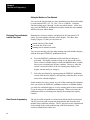
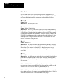
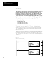
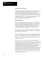
AllenBradley
Real Time Clock
Module
(Cat. No. 1771-DC)
User
Manual
Table of Contents
Introduction . . . . . . . . . . . . . . . . . . . . . . . . . . . . . . . . . . .
11
General . . . . . . . . . . . . . . . . . . . . . . . . . . . . . . . . . . . . . . . . . . .
Module Features . . . . . . . . . . . . . . . . . . . . . . . . . . . . . . . . . . . .
Applications . . . . . . . . . . . . . . . . . . . . . . . . . . . . . . . . . . . . . . . .
11
11
12
Module Preparation and Installation . . . . . . . . . . . . . . . . . .
21
General . . . . . . . . . . . . . . . . . . . . . . . . . . . . . . . . . . . . . . . . . . .
Panel Switches and Display . . . . . . . . . . . . . . . . . . . . . . . . . . . .
Reset Switch and Programming Plug . . . . . . . . . . . . . . . . . . . . . .
Battery Installation . . . . . . . . . . . . . . . . . . . . . . . . . . . . . . . . . . .
Power Requirements . . . . . . . . . . . . . . . . . . . . . . . . . . . . . . . . .
Chassis Location and Keying . . . . . . . . . . . . . . . . . . . . . . . . . . .
Specifications . . . . . . . . . . . . . . . . . . . . . . . . . . . . . . . . . . . . . .
21
21
24
25
26
26
27
Operation and Programming . . . . . . . . . . . . . . . . . . . . . . .
31
General . . . . . . . . . . . . . . . . . . . . . . . . . . . . . . . . . . . . . . . . . . .
Setting Time and Calendar from the Front Panel . . . . . . . . . . . . . .
Displaying Time and Calendar from the Front Panel . . . . . . . . . . .
Block Transfer Programming . . . . . . . . . . . . . . . . . . . . . . . . . . . .
31
31
34
34
Chapter
1
Introduction
General
The Real Time Clock Module (cat. no. 1771-DC) lets you or the PC
processor read or set real time and date information. Current time and
date information is block-transferred to and from the PC processor data
table for control and reporting purposes. The clock module can be used
with any of the following Allen-Bradley PLC Processors that have block
transfer capability and use the 1771 I/O structure.
Module Features
You can set or read the time and date through the front panel pushbutton
switches and 4-digit liquid crystal display (LCD) (Figure 1.1). You can
program the PC processor to set or read time and calendar information
automatically. Also, you can disable the time setting function to guard
against unauthorized changes to an installed clock module.
Figure 1.1
Real Time Clock Module
Liquid
Crystal
Display
Pushbutton
Switches
17901
11
Chapter 1
Introduction
Time and calendar functions are displayed as numbers. For example,
Tuesday is designated by the module as the second day of the week. It is
displayed as a 2. The year 1984 is displayed as 84. The hour is displayed
in military 24 hour format, 3:00 pm = 15:00 hours. The clock module
corrects for leap year.
The clock module displays the time and date formatted by day of the
week, year, month, day of the month, hours, minutes, and seconds. The
clock module also measures time in milliseconds. The module maintains
quartz crystal accuracy of 60 seconds per month and timer accuracy of
+0.25ms, -1.25ms (non-cumulative) over the normal operating
temperature of 0oC to +60oC. It uses a standard 9V alkaline battery for
backup and reports self-diagnostic information whenever time and date
information is read to the PC processor.
Applications
The accuracy and convenience of the clock module let you program many
control and reporting applications such as:
energy management
process synchronization
time and event correlation
calendar scheduling
accurate millisecond timing
accurate timing of power failures
accurate rate calculations
You can use the clock module with other bulletin 1771 I/O modules in a
variety of time-dependent applications.
12
Chapter
2
Module Preparation and Installation
General
The clock module generates accurate calendar and time data, performs
continuous diagnostic tests, has battery backup to retain its functions
during a power failure, responds to read and write block transfers from the
PC processor, and has two buffer memories, each with a capacity of nine
16-bit words.
The buffer write-only memory holds new calendar and time data received
from the PC processor or entered from the front panel. The buffer
read-only memory holds current calendar and time data that the module
can transfer to the PC processor or display through the front panel LCD.
Panel Switches and Display
The front panel of the clock module contains two pushbutton switches and
a 4-digit LCD (Figure 2.1).
Figure 2.1
Pushbutton Switches and Display
14:06
17902
21
Chapter 2
Module Preparation and Installation
Pushbutton Switches
Two pushbutton switches labeled FUNCTION and DISPLAY are near the
center of the front panel. They set time and calendar functions. The
DISPLAY pushbutton switch changes the display of time and calendar
information. These switches are described in sections titled “Setting Time
and Calendar from the Front Panel” and “Displaying Time and Calendar
from the Front Panel.”
Display
The LCD shows calendar, time, and diagnostic information.
You can display calendar and time information in any one of the
following formats (Figure 2.2):
month with day of the month
year with day of the week
running time in minutes and seconds
running time in hours and minutes
The display of calendar and time information is covered in section titled
“Displaying Time and Calendar from the Front Panel.”
Figure 2.2
Display Formats
Calendar Functions
701
22
Running Time Functions
05:37
July 1
Minutes : Seconds
83 5
14:06
1983 Friday
Hours : Minutes
(Colon Blinks)
11217
Chapter 2
Module Preparation and Installation
Display of Diagnostics
The module displays fault and alarm diagnostics. A battery low condition
is indicated by the non-blinking display of a single dot beneath the colon
in the center of the display (Figure 2.3). When the dot is first displayed,
24 hours of battery operation remain.
Figure 2.3
Battery Low Indicator
14:06
.
Battery Low Indicator
(Does Not Blink)
11218
The module indicates that power has been restored following a total
power failure (no battery backup) by blinking the display of eights in its
LCD. The blinking eights display indicates that previous calendar and
clock data have been lost, that the calendar and clock functions have
ceased, and that the module’s calendar and clock should be reset. When a
battery has been inserted in an unpowered clock module, the blinking
eights display indicates that the module’s calendar and clock are ready to
be set. Battery backup allows 100 hours of clock operation during power
failures or brownouts.
If the module detects an internal fault, the module’s clock will cease and a
non-blinking error number will appear in the right-most digit space of the
LCD. Error numbers are used during factory diagnosis and repair. In the
event that an error number is displayed, proceed as follows:
1. Power-down the I/O chassis.
CAUTION: Removing and inserting and I/O module when the
I/O chassis is powered can result in possible damage to module
circuitry.
2. Remove the clock module.
3. Press the reset switch (see “Reset Switch”).
23
Chapter 2
Module Preparation and Installation
4. Re-install the module.
5. Power-up the I/O chassis.
6. Set the clock and calendar, and start the clock using the procedure in
section titled “Setting Time and Calendar from the Front Panel.”
If the clock and calendar cannot be set or if the module’s clock will not
start, return the clock module to your nearest authorized field service or
sales office for repair.
Reset Switch and Programming
Plug
The lower rear section of the clock module contains a reset switch and a
programming plug (Figure 2.4).
Figure 2.4
Reset Switch and Programming Plug
Reset
Switch
Programming
Plug
17903
Reset Switch
You can reset the module’s clock and calendar functions by pressing and
releasing the reset switch. The LCD displays blinking eights indicating
that the module’s clock and calendar functions have ceased and are ready
to be set.
24
Chapter 2
Module Preparation and Installation
You can access the reset switch only when the module (with battery
backup) has been removed from the I/O chassis. Pressing the reset switch
has the same effect as temporarily disconnecting the battery.
Programming Plug
As a safeguard, you can prevent unauthorized changes to the module’s
clock and calendar by means of a programming (jumper) plug. The plug
disables the FUNCTION pushbutton switch on the front panel but does
not disable the DISPLAY pushbutton switch.
You insert the plug on two adjacent pins of a 3-pin assembly (Figure 2.5).
Place the plug on the upper two pins when setting the clock and calendar
functions and when you do not want to disable the FUNCTION
pushbutton switch. Place the plug on the lower two pins to disable the
FUNCTION pushbutton switch.
Figure 2.5
Programming Plug Positions
3Pin
Assembly
3Pin
Assembly
Programming
Plug
Programming
Plug
Plug Position for
Setting Functions
Battery Installation
Plug Position Disables
FUNCTION Switch
11219
The battery compartment is under the clock module’s lower front panel.
To open the compartment, hook your finger over the upper edge of the
hinged cover and pull the cover open.
Connect the battery to the 9Vdc battery connector. When inserting the
battery, be sure that the connecting wires are not pinched by the hinged
cover as you snap the cover into place.
Use a commercial 9Vdc alkaline battery such as Eveready 522 or Duracell
1064A for the backup battery. Battery life is 100 hours total for
intermittent or prolonged power outage. Once the “battery low”
25
Chapter 2
Module Preparation and Installation
indication is displayed and if backplane power is not restored, the battery
must be changed within 24 hours or the module’s clock and calendar
functions will cease. Do not change the battery during a power failure
because clock and calendar data will be lost. For dependable backup
operation, replace the battery annually or whenever the “battery low”
indicator is illuminated or lights up.
CAUTION: Do not replace the battery during a power outage
or the clock and calendar functions will cease and the data will
be lost.
Power Requirements
Under normal operation, the clock module draws all of its power, 350mA,
from the I/O chassis backplane. During a power outage the backup
battery powers only the module’s clock.
Chassis Location and Keying
Place the single-slot clock module in any bulletin 1771 I/O chassis I/O
module slot.
The clock module is not keyed. Other bulletin 1771 I/O modules can be
inadvertently placed in the slot reserved for the clock module. However,
the clock module cannot be placed in a keyed I/O slot.
26
Chapter 2
Module Preparation and Installation
Specifications
Accuracy
• Total variation with time over the operating range of the module (0 to 600C): 60 seconds per month
• Timing accuracy (independent of transfers):
+0.25ms and 1.25ms
Module Current Requirement
• 350 mA max @ 5V DC from the backplane
• 5.0mA max from backup battery during a power failure
Backup Battery
• Voltage: 9V DC
• Type: Alkalinesuch as Duracell 1604A, Eveready 522, or equivalent
• Life: One year standby when module is powered by the backplane; up to 100 hours during
a power failure including 24 hours from battery low indication until the clock ceases
Module Location
• Any bulletin 1771 I/O chassis single I/O slot location
Ambient Temperature Rating
• 00C to 600C operational
• 300C to 700C storage
Humidity Rating
• 5 to 85% (without condensation)
Keying
• None
27
Chapter
3
Operation and Programming
General
Calendar and time functions can either be set and read manually or be set
and read by the PC processor. Upon initial installation of the module or
upon recovery from a complete power failure (not battery backup), you
must set the calendar and clock functions to start module operation. This
chapter describes how you set and read the calendar and time functions
from the front panel, and how you program block transfers so that
calendar and time functions can be set and read by the PC processor.
Setting Time and Calendar from
the Front Panel
The seven time and calendar functions are listed in the order that you set
them.
day of the week
year
month
day of the month
hours
minutes
seconds
Set the time and calendar functions initially when the clock module is
installed, or following a power failure if battery backup was inoperative.
The display will blink eights when power is applied. The blinking eights
display indicates that clock module functions are not operating but are
waiting to be set.
You can set or reset the time and calendar functions conveniently using
the front panel FUNCTION and DISPLAY pushbutton switches. Briefly
press the FUNCTION switch to advance the calendar-set or time-set
function. Press the DISPLAY switch until the display reaches the setting
you want to enter.
The seven calendar and time functions are listed in the order that you
initially set them (Table 3.A). The table includes the numerical range for
each function such as 1 through 7 for day of the week, the initial display
for each function, and an example setting for each function. Once you
have set the clock and calendar, you can change any of the settings
independently.
31
Chapter 3
Operation and Programming
1.
Start the function selecting and setting procedure by pressing the
FUNCTION pushbutton until the day of the week display is
obtained. A1 appears in the right-most position on the display.
If another initial display should appear (Table 3.A), use only the
FUNCTION pushbutton switch to advance through the remaining
functions until the day of the week display appears. Each time you press
the FUNCTION pushbutton switch, hold it for a second or two until the
display advances to the next function.
Table 3.A
Calendar and Time Functions
Function
Day of the Week
Range
17
Initial
Display
[
1]
Example Setting
Example
Display
Tuesday, day 2
[
2]
Year
0099
[0 0
]
1984
[8 4
Month
112
[ 1
]
June, 6th month
[ 6
Days of the Month
131
[
13th day
[
Hours
023
[ 0:
3:00pm = 15:00 hours
[1 5:
Minutes
059
[
:0 0]
45 minutes
[
Seconds
059
[
:0 0]
27 seconds
[
01]
]
]
]
1 2]
]
:4 5]
:2 7]
Press FUNCTION
display set time in hrs:min (the
colon is not blinking)
[1 5: 4 5 ]
Press DISPLAY
a) displays date for several
seconds
[ 6 1 3]
b) displays running time (the
colon is blinking
[1 5: 4 5 ]
The module clock starts when
the DISPLAY pushbutton
switch is pressed.
2.
32
Enter the setting that you want by pressing the DISPLAY pushbutton
switch until the display counts up to your desired setting, then release
it.
Chapter 3
Operation and Programming
If you hold it too long and the count exceeds your setting, continue
pressing the DISPLAY pushbutton until the count recycles through the
entire range.
3.
Continue selecting and setting the remaining calendar and time
functions in this manner.
When you complete a setting, press the FUNCTION pushbutton switch
until the next initial display of a function appears. Then press the
DISPLAY pushbutton switch until the desired setting is reached. Release
it when the LCD displays your desired setting.
The last two steps of the procedure must be completed before the clock
module begins timing.
4.
After selecting and setting the seconds function, press the
FUNCTION pushbutton switch. The set time will be displayed in
hours: minutes but the colon will not blink because the module’s
clock is not running.
5.
Press the DISPLAY pushbutton switch to start the module’s clock.
The month and day are displayed. After several seconds, the display
automatically changes to the current time displayed in hours:
minutes. The colon blinks to indicate that the module’s clock is
running.
Important: The module’s clock starts the instant that the DISPLAY
pushbutton switch is pressed (not released) during step 5.
Important: You can change date settings and the hour setting without
interrupting the module’s clock. However, the clock stops while you
change the minute or second setting. Refer to the description of the wait
bit (bit 03) in section titled “Status Word” for additional information on
clock stoppage.
Important: The time and calendar functions can also be set and the
module started by a single write block transfer if you program the PC
processor to perform this operation.
33
Chapter 3
Operation and Programming
Setting the Module to a Time Standard
You can set the clock module to a time standard such as the one broadcast
by radio station WWV (2.5, 5.0, 10.0, 15.0 or 25.0MHz). Complete
function-setting steps 1 through 4 to the next whole minute. As the last
step, press the DISPLAY pushbutton switch the instant the time standard
indicates the next whole minute.
Displaying Time and Calendar
from the Front Panel
Running time in hours: minutes is displayed on the front panel LCD
unless you select another calendar or time display. The three other
displays (Figure 2.2) that you can select are:
month with day of the month
year with day of the week
running time in minutes/seconds
You can conveniently select the other running time and calendar displays
with the front panel DISPLAY pushbutton switch.
6.
Press the DISPLAY pushbutton switch until the next display is
presented. The display remains as long as you depress the switch.
Once released, calendar displays remain an additional three seconds,
then revert to running time in hours: minutes. However, when the
switch is released in either of the two running time displays, the
display remains until you change it.
7.
Select the next display by again pressing the DISPLAY pushbutton
switch while the new display is still present (within the three second
interval for calendar displays).
In this manner you select, in turn, any one of the remaining three displays.
Once you release the DISPLAY pushbutton switch in a calendar display,
you allow the calendar display to revert to running time in hours: minutes
if you do not press the pushbutton switch again. When you release the
pushbutton switch in a running time display, the running time display
remains.
Block Transfer Programming
34
The clock module responds to read and write block transfer instructions.
The PC processor reads current time and calendar data from the clock
module using read block transfers. The PC processor writes calendar and
clock settings to the clock module using write block transfers. Nine
words are transferred in either case.
Chapter 3
Operation and Programming
WARNING: Use only Allen-Bradley authorized programming
devices to program Allen-Bradley programmable controllers.
Using unauthorized programming devices may result in
unexpected operation, possibly causing equipment damage
and/or injury to personnel. The Allen-Bradley Company will
not be responsible or liable for any damages, whether direct,
indirect, or consequential, arising out of the use of such
unauthorized programming devices.
Data Organization
The same nine words are transferred in either a read or write operation
(Table 3.B). During a write operation, status word 0 and millisecond
word 8 are transferred with zero value. During a read operation, the PC
processor monitors the clock module’s status as determined by status
word 0, and reads the values of the remaining eight words including the
millisecond word 8. When you program the block transfer instruction, set
the block length to the default value or to nine. Any other block length
can cause improper operation or prevent a block transfer.
Table 3.B
Data Organization
Data Format
Word
Name
Range
Bit Numbers
17
14
13
10
07
04
03
00
01
Status Word
01
0
0
00BB
B B B B2
1
Day of Week
17
0
0
0
D3
2
Year
0099
0
0
D
D
3
Month
0112
0
0
D
D
4
Day of Month
0131
0
0
D
D
5
Hours
0023
0
0
D
D
6
Minutes
0059
0
0
D
D
7
Seconds
0059
0
0
D
D
81
Milliseconds
000999
0
D
D
D
1
read only
2
B = binary bit
3
D = BCD digit
35
Chapter 3
Operation and Programming
Status Word
Six bits in the status word are used to report module diagnostics. The
diagnostic word is included in each read block transfer of data to the PC
processor. Bit functions of the status word are described as follows:
Bit: 17-06
Name: None
Description: Not used, set to zero.
Bit: 05
Name: Module Uninitialized
Description: Set (to 1) if the clock module loses power without battery
backup. (Total power failure is also indicated by flashing eights in the
LCD). Reset (to 0) when the clock module receives a write block transfer
of time and/or calendar data from the PC processor or when you press the
FUNCTION pushbutton switch to set the time from the front panel. You
should program a rung to examine this bit to be sure that date and time
data are valid before using the data.
Bit: 04
Name: Battery Low
Description: Set when the battery has approximately one day of battery
life remaining, when the battery is dead, or when no battery is installed.
Reset when a new battery is installed. You should program a rung to
examine this bit to activate a visual and/or audible signal when the bit
goes high.
Bit: 03
Name: Wait
Description: Set while you are setting the time or calendar from the front
panel. Reset when the module’s clock starts. The clock module can be
started manually from the front panel or by a write block transfer from the
PC processor.
If the module’s clock is running when you begin the time setting
procedure for minutes or seconds, the clock stops and the module sets the
wait bit when you press the DISPLAY pushbutton (step 2).
If the module is powered but the clock is not running when you begin the
time setting procedure for minutes or seconds, the module sets the wait bit
when you press the FUNCTION pushbutton switch (step 1).
36
Chapter 3
Operation and Programming
The module can receive a write block transfer from the PC processor
when the wait bit is set, but the clock module will not start as a result.
The wait bit will not be affected when changing the display of time or
calendar from the front panel in steps 6 and 7.
Bit: 02
Name: Invalid Value
Description: Set if a write block transfer contains a time or calendar
value out of range. If this happens, the module will substitute the lowest
displayed value for the out of range value. Reset after a valid value is
transferred in a subsequent write block transfer.
Bit: 01
Name: Communication Error
Description: Set when the module detects a PC communication fault
during a write block transfer. If this happens, the clock module ignores
the write block transfer and continues running with the previous data.
Reset by a subsequent write block transfer after proper communication is
restored. You should program a rung to examine this bit so that corrective
action can be taken when a communication error occurs.
Bit: 00
Name: Valid Time
Description: Set when the clock module is running. Reset when the wait
bit is set or when the module stops as a result of a total power failure.
Sample Programs
The format for programming block transfer depends on your PC
processor. If you are using a controller with a 3-position keyswitch
(Mini-PLC-2 or PLC-2/20 controller) use multiple get instructions. If you
are using a controller with a 4-position keyswitch (Mini-PLC-2/15,
PLC-2/30) or a PLC-3 family controller use block format instructions.
The examples that follow use block format instructions. Refer to the
Programming and Operations Manual of your processor for additional
information on these instructions.
Assume that the module is located in rack 1, module group 2, slot 0.
37
Chapter 3
Operation and Programming
PLC-2 Family
The control byte and status byte corresponding to the module’s address in
the output and input image tables are at word addresses 0128 and 1128
(lower bytes), respectively, in this example. The addresses of the enable
bit and done bit for the block transfer read instruction are 012/07 and
112/07, respectively. The addresses of the enable bit and done bit for the
block transfer write instruction are 012/06 and 112/06, respectively. The
following addresses are also used in the example (Figure 3.1):
data address 0508
module address 1208
file words 1508-1608 (read)
file words 2508-2608 (write)
When rung 1 is true, the enable bit 012/17 is set. The data from the
module is transferred into PC processor data table words 1508 through
1608. After the nine words of data are transferred to the PC processor,
done bit 112/07 is set.
When rung 2 is true, the enable bit 012/06 is set. Data to be transferred to
the module is stored in the PC processor data table words 2508 through
2608. After the nine words of data are transferred to the module, done bit
112/06 is set.
Figure 3.1
Block Transfer, PLC2 Family
1
BLOCK XFER READ
DATA ADDR:
MODULE ADDR:
BLOCK LENGTH:
FILE:
2
050
120
09
150160
BLOCK XFER WRITE
DATA ADDR:
MODULE ADDR:
BLOCK LENGTH:
FILE:
050
120
09
250260
012
EN
07
112
DN
07
012
EN
06
112
DN
06
11220
38
Chapter 3
Operation and Programming
PLC-3 Family
The PLC-3 block transfer control file is in binary file 2, words 0 through
9, in this example. Addresses of the control and status bits for the block
transfer read instruction are FB002:0000/12(CNTL 12) for the enable bit,
and FB002:0000/15(CNTL 15) for the done bit. Addresses of the control
and status bits for the block transfer write instruction are
FB002:0000/02(CNTL 02) for the enable bit, and FB002:0000/05(CNTL
05) for the done bit.
Store block transfer read and write data in any two available decimal files
designated by the appropriate section, file number, and starting word
address such as FD010:0000 for read data, and FD011:0000 for write data
(Figure 3.2).
When rung 1 is true, the enable bit CNTL 12 is set. The data from the
module is transferred into the PC processor data table in decimal file 10
words 0 through 8. After the nine words of data are transferred to the PC
processor, the done bit CNTL 15 is set.
When rung 2 is true, the enable bit CNTL 02 is set. Data to be transferred
to the module is stored in decimal file 11 words 0 through 8. After the
nine words of data are transferred to the module, done bit CNTL 05 is set.
Figure 3.2
Block Transfer, PLC3 Family
1
BTR
BLOCK XFER READ
RACK:
GROUP:
MODULE:
DATA:
LENGTH =
CNTL:
2
012
2
0 = LOW
FD010:0000
09
FB002:0000
BTW
BLOCK XFER WRITE
RACK:
GROUP:
MODULE:
DATA:
LENGTH =
CNTL:
012
2
0 = LOW
FD011:0000
09
FB002:0000
CNTL
EN
12
CNTL
DN
15
CNTL
ER
13
CNTL
EN
02
CNTL
DN
05
CNTL
ER
03
11257
39
Chapter 3
Operation and Programming
Programming Considerations
Additional programming rungs should be added at your discretion. Data
from the module should be stored temporarily in a buffer file until the
block transfer done bit is set indicating a valid transfer. Program a
boundary word after the last block transfer data address to prevent the PC
processor from searching further in the accumulated value area for block
transfer data addresses (PLC-2 Family). Program a watchdog timer and
an indicating device to detect and signal the possible loss of
communication with block transfer modules.
Block Transfer Timing
Only one read or write block transfer can occur at a time. When the PC
processor is reading clock, calendar, and diagnostic data, another block
transfer is inhibited for 1.6ms until the time changes and the module’s
buffer memory is updated. When the PC processor is writing new clock
and calendar settings to the module, subsequent block transfers are
inhibited for 2.0ms until the new calendar and clock values are set.
The module time of 2.0ms maximum for a block transfer is shorter than
the PC processor scan time. Therefore, the module is ready whenever it
receives a request to transfer data.
The clock module continuously stores time and calendar data in its buffer
memory. The moment it receives a request for a block transfer from the
PC processor, it latches the data in memory. The data transferred to the
PC processor is the data that the module latched when it received the
block transfer request.
The clock module can be used as a millisecond timer allowing the PC
processor to perform rate calculations. When you use the clock module as
a millisecond timer, you can achieve accurate differential times by starting
and stopping the clock in the same scans that the PC processor reads,
respectively, the initial and final measured values. This is done by
enabling the timer with a write block transfer in the same scan that the PC
processor reads the initial measured value, and reading the timer’s
accumulated value with a read block transfer in the same scan that the PC
processor reads the final measured value. Locate the clock module in a
slot adjacent to the I/O module from which the measured values are read.
The differential accuracy is not affected by block transfer delays when
operating in a local I/O system.
310
Chapter 3
Operation and Programming
The time required for a block transfer depends on factors independent of
the clock module. The delay before the next transfer depends typically on
the processor scan time, the number of block transfer instructions enabled
simultaneously in the same scan, the number of words transferred, system
layout for a PLC-3 controller, and whether the PLC-2 family system
contains local or remote I/O. Remote I/O generally takes longer than
local I/O.
311
Index
A
Accuracy, See Specifications, 27
L
Location in Chassis, 26
Applications, 12
B
Battery
Installation, 25
Specifications, 27
P
PC Processor Compatibility, 11
Power Failure Indication, 23
Power Requirements, 26
Block Transfer
Programming, 34
Timing, 310
Programming
Block Transfer,
Considerations,
PLC 2 Family,
PLC 3 Family,
Buffer Memory, 21
Programming Plug, 25
Battery Low Indication, 23
34
310
38
39
Pushbuttom Switches, 22
D
Data Organization, 35
R
Diagnostic Display, 23
Rate Calculations, 310
Display Formats, 22
Reset Procedure, 24
Reset Switch, 24
F
Features, 11
Functions
Displaying from Front Panel, 34
Setting from Front Panel, 31
Setting to a Standard, 34
K
Keying, 26
S
Securing the Settings, 25
Specifications, 27
Starting the Clock, 33
Status Word, 36
AllenBradley, a Rockwell Automation Business, has been helping its customers improve pro
ductivity and quality for more than 90 years. We design, manufacture and support a broad range
of automation products worldwide. They include logic processors, power and motion control
devices, operator interfaces, sensors and a variety of software. Rockwell is one of the worlds
leading technology companies.
Worldwide representation.
Argentina • Australia • Austria • Bahrain • Belgium • Brazil • Bulgaria • Canada • Chile • China, PRC • Colombia • Costa Rica • Croatia • Cyprus • Czech Republic •
Denmark • Ecuador • Egypt • El Salvador • Finland • France • Germany • Greece • Guatemala • Honduras • Hong Kong • Hungary • Iceland • India • Indonesia •
Ireland • Israel • Italy • Jamaica • Japan • Jordan • Korea • Kuwait • Lebanon • Malaysia • Mexico • Netherlands • New Zealand • Norway • Pakistan • Peru •
Philippines • Poland • Portugal • Puerto Rico • Qatar • Romania • RussiaCIS • Saudi Arabia • Singapore • Slovakia • Slovenia • South Africa, Republic • Spain •
Sweden • Switzerland • Taiwan • Thailand • Turkey • United Arab Emirates • United Kingdom • United States • Uruguay • Venezuela • Yugoslavia
AllenBradley Headquarters, 1201 South Second Street, Milwaukee, WI 53204 USA, Tel: (1) 414 3822000 Fax: (1) 414 3824444
Publication 1771-6.5.17 - February, 1986
Supersedes
1771-824
- September,
1983 1986
Publication
1771-6.5.17
- February,
PN 955099-40
Copyright 1986 AllenBradley Company, Inc. Printed in USA