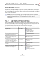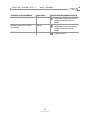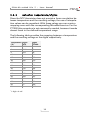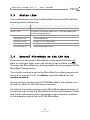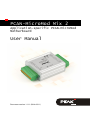
1
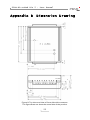
PCAN-MicroMod Mix 2
Application-specific PCAN-MicroMod
Motherboard
User Manual
Document version 1.11.1 (2014-03-11)
PCAN-MicroMod Mix 2 – User Manual
Products taken into account
Product Name
Model
Part number
PCAN-MicroMod Mix 2
Including casing and
PCAN-MicroMod
IPEH-002203
PCAN-MicroMod Configuration
Version 2.5
(Windows software)
CANopen® and CiA® are registered community trade marks of CAN in Automation
e.V.
All other product names mentioned in this document may be the trademarks or
registered trademarks of their respective companies. They are not explicitly marked
by “™” and “®”.
© 2014 PEAK-System Technik GmbH
PEAK-System Technik GmbH
Otto-Roehm-Strasse 69
64293 Darmstadt
Germany
Phone: +49 (0)6151 8173-20
Fax:
+49 (0)6151 8173-29
www.peak-system.com
[email protected]
Document version 1.11.1 (2014-03-11)
2
PCAN-MicroMod Mix 2 – User Manual
Contents
1
1.1
1.2
1.3
2
2.1
2.2
2.3
3
Introduction
4
Properties at a Glance
Prerequisites for Operation
Scope of Supply
Hardware Configuration
4
6
6
7
Pull-up/Pull-down Circuits for the Digital
Inputs
Measuring Range Extension of the Analog
Inputs
Using a PT1000 with Three-Wire Connection
Operation
8
9
10
11
3.1 Port Assignment
3.2 Configuration Program
3.2.1
System Prerequisites
3.2.2
Installing the Program
3.2.3
Creating a Configuration
3.2.4
Applicable MicroMod Services
3.2.5
Relation Temperature/Digits
3.3 Status LEDs
3.4 Several MicroMods on the CAN Bus
11
12
12
13
13
14
16
17
17
4
19
Technical Specifications
Appendix A
CE Certificate
22
Appendix B
Dimension Drawing
23
3
PCAN-MicroMod Mix 2 – User Manual
1
Introduction
The motherboards for PCAN-MicroMod provide an applicationoriented environment. Typical characteristics of this product group
include a wide supply voltage range and the protective circuit for
the inputs and outputs. CANopen® firmware is available for all
PCAN-MicroMod motherboards.
The Mix 2 motherboard serves common analog and digital requirements and supports temperature measurement.
Note: This manual only refers to the motherboard as base for a
PCAN-MicroMod and to the standard firmware. For the PCANMicroMod and the configuration program PCAN-MicroMod
Configuration, there is separate documentation.
1.1
Properties at a Glance
Completely configurable using the Windows program PCANMicroMod Configuration
Communication through High-speed CAN (ISO 11898-2)
Operating voltage 11 to 26 V (8 to 26 V w/o use of analog
outputs)
Aluminum profile casing with spring terminal connectors
Top hat rail mounting option available
Extended operating temperature range from -40 to +85 °C
(-40 to +185 °F)
4
PCAN-MicroMod Mix 2 – User Manual
2 digital inputs:
• Pull-up or pull-down circuit selectable (for both together)
• High state at 5 to 18 V input voltage
• Schmitt trigger behavior, inverting
• Low-pass behavior
• Parallel connection of a frequency input for alternative use
(e.g. fast status changes, countings)
2 inputs for connecting a thermistor and a platinum sensor
PT1000, measuring range each 0 to 70 °C (32 to 158 °F)
3 analog inputs:
• Pull-down circuit
• Measuring range unipolar 0 to 4.1 V
• Resolution 10 bits
• Sampling rate 1 kHz
• Measuring range extension possible
• Low-pass behavior
• Protection against undervoltage and overvoltage
1 digital output:
• Fast low-side switch, max. 55 V, 0.75 A
• Short circuit protection
1 analog voltage output:
• Voltage range 0 to 10 V (based on 16-bit PWM)
• Load ability: 15 mA, short-circuit proof
1 analog current output with 0 to 20 mA (based on 16-bit PWM)
Status LEDs for power supply and digital output
5
PCAN-MicroMod Mix 2 – User Manual
1.2
Prerequisites for Operation
Power supply in the range of 11 to 26 V DC (8 to 26 V w/o use of
analog outputs)
For creating and transferring configurations: computer with
Windows 8, 7, Vista, XP (32-bit or 64-bit) and a CAN interface
from the PCAN series
1.3
Scope of Supply
PCAN-MicroMod
PCAN-MicroMod motherboard in casing including mating
connectors
PCAN-MicroMod Configuration for Windows
Manual in PDF format
6
PCAN-MicroMod Mix 2 – User Manual
2
Hardware Configuration
You can customize the motherboard by modifying the hardware.
The following subsections contain descriptions about possible
modifications.
Accessing the Motherboard
In order to carry out the modifications described in the following
sections, unscrew the lid of the casing and pull off the MicroMod
from the motherboard.
Attention! Electrostatic discharge (ESD) can damage or destroy
components on the motherboard or the PCAN-MicroMod. Take
precautions to avoid ESD when handling the boards.
Remounting the MicroMod
When you remount the MicroMod, take notice of the white triangular marks on each the motherboard and the MicroMod (upper left
corner). These marks must align.
Figure 1: Positioning of the MicroMod
7
PCAN-MicroMod Mix 2 – User Manual
2.1
Pull-up/Pull-down Circuits for the
Digital Inputs
At delivery the digital inputs are set to pull-up circuits. You can set
them together to pull-down circuit. This is done by repositioning a
0-Ohm resistor.
*
Digital inputs
Pull-up (+Ub)*
Pull-down (GND)
DI 0 and DI 1
R73 (0 Ω)
R74 (0 Ω)
Setting at delivery
Figure 2: Position R73/R74 (bottom side of the PCB)
Attention! Double-check for an inadvertent short circuit after
altering the setup.
8
PCAN-MicroMod Mix 2 – User Manual
2.2
Measuring Range Extension of the
Analog Inputs
You can extend the measuring range of each analog input to a
higher maximum voltage than 4.1 Volts by using a voltage divider.
On delivery of the motherboard the resistor positions R28 to R30 on
the bottom side of the PCB are not equipped. By inserting a resistor
Rx with a value calculated with the following formula the measuring
range is extended to the desired maximum voltage UMB.
Rx =
2400 Ω
(UMB > 4.1V)
UMB
−1
4.1V
Figure 3: Position R28 to R30 (bottom side of the PCB)
9
PCAN-MicroMod Mix 2 – User Manual
2.3
Using a PT1000 with Three-Wire
Connection
At delivery the Mix 2 motherboard is configured to be used with a
PT1000 thermistor with two-wire connection. If you would like to
use a PT1000 with three-wire connection instead (e.g. in case of a
long connection cable), you must remove the 0-Ohm resistor on the
PCB located on position R76.
Figure 4: Position R76
10
PCAN-MicroMod Mix 2 – User Manual
3
Operation
3.1
Port Assignment
The motherboard has two connectors, J1/2 on the left and J3 on the
right. The port assignment is as follows:
Figure 5: Ports of the Mix 2 motherboard
Port name
J1/2
Function
+Ub
Operating voltage 11 - 26 V DC, w/o AOut 8 - 26 V DC
GND
Digital ground
CAN_L
CAN_H
N/C
Differential CAN signal
Not connected
AIn 0
AIn 1
Analog input
AIn 2
AIn 3 (NTC)
Connection thermistor (against AGND)
AGND
Analog ground
11
PCAN-MicroMod Mix 2 – User Manual
Port name
J3
Function
GND
Digital ground
DOut 0
Digital output
DIn 1
DIn 0
Digital input
AOut 1
Analog output for current (PWM)
AOut 0
Analog output for voltage (PWM)
PTE
PT2
PT1
AGND
3.2
Temperature measurement
PT1000
Reference point
Input
Input
Analog ground
Configuration Program
In order to create and transfer MicroMod configurations the Windows software PCAN-MicroMod Configuration is used. This section
covers basic points about installation and use of the program with
the Mix 2 motherboard.
You'll find detailed information about the use of PCAN-MicroMod
Configuration in the related documentation which is invoked via the
program (e.g. with F1).
3.2.1
System Prerequisites
Windows 8, 7, Vista, XP (32-bit or 64-bit)
Computer with CAN interface of the PCAN series (for transferring a configuration to the PCAN-MicroMod via CAN)
12
PCAN-MicroMod Mix 2 – User Manual
3.2.2
Installing the Program
Under Windows install the program from the supplied CD. Start the
corresponding installation routine by using the CD navigation going
to Tools > PCAN-MicroMod Configuration 2.5.x.
3.2.3
Creating a Configuration
When you start creating a new configuration in PCAN-MicroMod
Configuration, the dialog box Board Type appears in order to select
the type of the used motherboard. The necessary settings are
explained in the following.
Figure 6: PCAN-MicroMod Configuration: selection of the Mix 2 motherboard
Board Type: PCAN-MicroMod Mix 2
Module No: 0
The module number of the MicroMod on the Mix 2 motherboard is
set to 0 at delivery and is relevant if you want to configure more
than one MicroMod on the same CAN bus. See also section 3.4
Several MicroMods on the CAN Bus on page 17.
13
PCAN-MicroMod Mix 2 – User Manual
Bitrate MicroMod: 500 kbit/s
At delivery the MicroMod is set to a bit rate of 500 kbit/s. A change
of this setting will take effect after sending the completed configuration to the MicroMod.
Note: For the first transfer of a configuration to the module it
must be integrated in a CAN network with a bit rate of
500 kbit/s.
3.2.4
Applicable MicroMod Services
The motherboard's inputs and outputs are controlled by the services of the MicroMod. The following table shows the assignment of
the motherboard functions to the MicroMod services.
Function on motherboard
Port name
Digital input
DIn 0, DIn 1
Access with MicroMod service(s)
Digital Input
Digital Function
Rotary Encoder
Frequency input (parallel to
channels DIn 0 and DIn 1)
Frequency Input
Digital output (higherfrequent state changes are
not possible)
DOut 0
Temperature measurment
thermistor (see also table in
section 3.2.5 on page 16)
AIn 3 (NTC)
Temperature measurement
PT1000
PTx
Digital Output
Analog Input
Curve
Analog Input
Curve
Analog input (see also table in AIn 2, AIn 3
section 3.2.5 on page 16)
Analog Input
Curve
Analog Hysteresis
14
PCAN-MicroMod Mix 2 – User Manual
Function on motherboard
Port name
Analog output for voltage
AOut 0
Analog output for current
(inverting)
AOut 1
LED DOut 7
DOut 7
Access with MicroMod service(s)
PWM and Frequency Output
(4 kHz recommended for
PWM)
PWM and Frequency Output
(4 kHz recommended for
PWM)
Digital Output
15
PCAN-MicroMod Mix 2 – User Manual
3.2.5
Relation Temperature/Digits
Since the NTC thermistor does not provide a linear correlation between temperature and the resulting voltage, the use of interpolation values can be expedient. With these values you can create a
mapping curve with the corresponding MicroMod service. For the
PT1000 this procedure is not necessarily needed, because it works
almost linear in the defined temperature range.
The following table provides the mapping between a temperature
and the resulting voltage or the digits respectively.
*
Temperature Digits*
(°C)
NTC
Digits*
PT1000
0
1023
2
2
1010
36
5
974
89
10
911
164
15
841
235
20
765
310
25
683
380
30
602
455
35
516
524
40
432
598
45
348
668
50
268
742
55
192
812
60
121
886
65
57
956
70
3
1023
1 digit ≡ 4 mV
16
PCAN-MicroMod Mix 2 – User Manual
3.3
Status LEDs
The motherboard including the MicroMod has three LEDs with the
following status indications:
LED
Indication
Power (green)
Power is applied.
DOut 7 (red)
Is linked to the digital output DO 7 of the MicroMod and
can be configured freely.
Activity (red)
Status of the PCAN-MicroMod:
blinking at 1 Hz
normal operation
blinking at 2 Hz
invalid or no configuration
blinking at 5 Hz
configuration mode
continuously on
internal MicroMod error
3.4
Several MicroMods on the CAN Bus
If you want to use several MicroMods on the same CAN bus and
want to configure them, each one needs its own module number.
That way the MicroMods are distinguishable for the program PCANMicroMod Configuration.
The module number is set on the MicroMod by solder jumpers and
lies in the range of 0 to 31. At delivery each MicroMod has the
module number 0.
During normal operation of the PCAN-MicroMod, the module number has no effect on the CAN communication.
For setting the solder jumpers on the MicroMod unscrew the top of
the casing and remove the MicroMod from the motherboard. Please
find further information about the assignment of module numbers
in the separate manual for the PCAN-MicroMod.
17
PCAN-MicroMod Mix 2 – User Manual
Attention! Electrostatic discharge (ESD) can damage or destroy
components on the motherboard or the PCAN-MicroMod. Take
precautions to avoid ESD when handling the boards.
Remounting the MicroMod
When you remount the MicroMod, take notice of the white triangular marks on each the motherboard and the MicroMod (upper left
corner). These marks must align.
Figure 7: Positioning of the MicroMod
18
PCAN-MicroMod Mix 2 – User Manual
4
Technical Specifications
Power supply
Operating voltage +Ub
11 - 26 V DC (±5 %), 8 - 26 V w/o AOut
Current consumption
max. 200 mA, typ. 35 mA at 12 V w/o load
Overvoltage protection
±30 V static, ±500 V surge
Ripple 5 V
< 50 mV (+Ub = 12 V, 200 mA load)
Ripple analog
< 20 mV
Reverse-polarity protection
extant; can get ineffective by the wiring with other
CAN nodes (danger of destruction of electronic
components)
Analog inputs
Count
3
Measuring range
0 to 4.1 V, extendable
Resolution
10 bits
Sampling rate
1 kHz
Source impedance
< 5 kΩ
Overvoltage protection
extant
Low-pass
fg = 66 Hz
Analog outputs
Count
2
Type
PWM based
Voltage AOut 0
0 - 10 V
Resolution
16 bits
Load ability AOut 0
15 mA
Current AOut 1
0 to 20 mA (inverting)
Load resistance AOut 1
< 100 Ω
19
PCAN-MicroMod Mix 2 – User Manual
Temperature input thermistor
Count
1
Reference sensor type
Thermistor EC95F103W (e.g. RS Components part
no. 151-237, form factor: bead) 1
Measuring range
0 to 70 °C (32 to 158 °F) corresponding 4.1 to 0 V
(antiproportional)1
Resolution
±1.0 °C (due to sensor)
Temperature input PT1000
Count
1
Sensor type
PT1000, two- or three-wire connection
Measuring range
0 to 70 °C (32 to 158 °F) corresponding 0 to 4.1 V
Resolution
10 bit
Resolution
±0,5 °C
Digital inputs
Count
2
Switching thresholds
UIH = 4 V; UIL = 3 V, contact or logic level
Input impedance
2.7 kΩ
Open input
Pull-up circuit, optional pull-down circuit
Overvoltage protection
extant
Low-pass
fg = 7 kHz
Special feature
Frequency inputs of the PCAN-MicroMod parallel
Digital/frequency output
1
Count
1
Maximum frequency
10 kHz (details: see user manual for the
PCAN-MicroMod)
Type
Low-side
Voltage proof
< 55 V
Output current
0.75 A (constant current)
Short circuit protection
extant; short-circuit current: 1.2 A
Other sensor type and measuring range on request
20
PCAN-MicroMod Mix 2 – User Manual
CAN
Transmission standard
High-speed CAN ISO 11898-2, typ. 500 kbit/s, setup
with PCAN-MicroMod Configuration (Windows
software)
Termination
none
CAN ID reserved for
configuration transfer
0x7E7
Module number at delivery 0
(for configuration transfer)
Peculiarity Interference Immunity
Tests
compliant to IEC 61000 and DIN EN 61326
Surge
±500 V (specification industrial sector: ±1 kV) 2
Line-conducted HF
compatibility
10 Veff (specification: 3 Veff)
Environment
Operating temperature
-40 - +85 °C (-40 - +185 °F)
Temperature for storage
and transport
-40 - +100 °C (-40 - +212 °F)
Relative humidity
15 - 90 %, not condensing
Ingress protection
(IEC 60529)
IP20
EMC
DIN EN 61326-1:2013-07
EC directive 2004/108/EG
Measures
2
Casing size (incl.
connectors)
55 x 68 x 24 mm
See also dimension drawing in Appendix B on page
23
Weight
109 g
This specification could only be fulfilled with ±500 V due to the available space.
Therefore, the motherboard should be used with a local power supply.
21
PCAN-MicroMod Mix 2 – User Manual
Appendix A
CE Certificate
22
PCAN-MicroMod Mix 2 – User Manual
Appendix B
Dimension Drawing
Figure 8: Top view and view of front side with connector.
The figure does not show the actual size of the product.
23