1
EtherCAT Remote I/O Terminal
GX-series
EtherCAT Slave Units
®
User’s Manual
GX-ID@@@@
GX-OD@@@@
GX-OC@@@@
GX-MD@@@@
GX-AD@@@@
GX-DA@@@@
GX-EC@@@@
XWT-ID@@
XWT-OD@@
Digital I/O Units
Analog I/O Units
Encoder Input Units
W488-E1-04
OMRON, 2010
All rights reserved. No part of this publication may be reproduced, stored in a retrieval system, or transmitted, in any form, or
by any means, mechanical, electronic, photocopying, recording, or otherwise, without the prior written permission of
OMRON.
No patent liability is assumed with respect to the use of the information contained herein. Moreover, because OMRON is
constantly striving to improve its high-quality products, the information contained in this manual is subject to change without
notice. Every precaution has been taken in the preparation of this manual. Nevertheless, OMRON assumes no responsibility
for errors or omissions. Neither is any liability assumed for damages resulting from the use of the information contained in
this publication.
Trademarks
• EtherCAT® is registered trademark and patented technology, licensed by Beckhoff Automation GmbH, Germany.
• ODVA, CIP, CompoNet, DeviceNet, and EtherNet/IP are trademarks of ODVA.
• Windows is a registered trademark of Microsoft Corporation in the USA.
• Sysmac and SYSMAC are trademarks or registered trademarks of OMRON Corporation in Japan and other
countries for OMRON factory automation products.
Other company names and product names that appear in this manual are the trademarks or registered trademarks of the relevant companies.
GX-series
EtherCAT Slave Units
User’s Manual
Revised November 2013
Introduction
Thank you for purchasing a GX-series EtherCAT Slave Unit.
This manual contains information you need to know to use the EtherCAT Slave Unit.
Before use, please make sure that you thoroughly read the manual and have a full understanding of the
products functions and performance.
After you finished reading this manual, please keep it in a convenient place.
Intended Readers
This manual is intended for the following individuals.
Those having electrical knowledge (certified electricians or individuals having equivalent knowledge)
and also being qualified for one of the following:
• Introducing FA equipment
• Designing FA systems
• Managing FA sites
GX-series EtherCAT Slave Unit User’s Manual
1
How to Read the Manual
Page Structure
This manual's page structure consists of the following.
Chapter title
Clause title
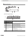
4 Installation and Wiring
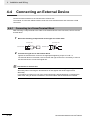
4-4
Connecting an External Device
Indicates the clause title
of the current page.
Connect an external device to the I/O terminal of a Slave Unit.
The method of connection differs between Units with screw terminal blocks and Units with e-CON
connectors.
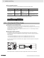
4-4-1
Connecting to a Screw Terminal Block
After mounting a crimp terminal to the cable of the external device to be connected, connect it to the
terminal block.
Section title
1
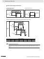
Mount the following crimp terminal to the signal line of the cable.
φ3.2 mm min.
3.2 mm min.
6.0 mm max.
6.0 mm max.
Operation
procedure number
2
Indicates operation procedure.
Icon
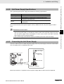
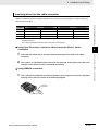
Connect the signal line to the terminal block.
Tighten the terminal block screws to the appropriate tightening torque of 0.5 N • m.
The terminal block is removable; remove the left and right screws if it is necessary to remove
the terminal block to connect the signal line.
Precautions for Correct Use
To remove the terminal block from the Slave Unit, loosen the left and right mounting screws
alternately. When mounting the terminal block as well, tighten the left and right screws
alternately.
If you tighten or loosen only one of the screws all the way without tightening or loosening the
other screw using an electric screwdriver, the terminal block will be distorted and cracked.
(Refer to the following section.)
4 - 10
GX-series EtherCAT Slave Unit User’s Manual
4 Installation and Wiring
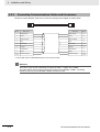
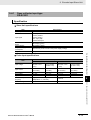
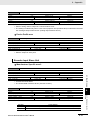
4-4-2
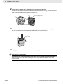
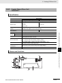
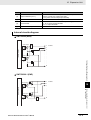
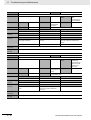
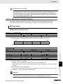
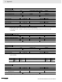
Connecting to e-CON Connector Terminals
Connect the dedicated e-CON connector to the cables of the external device to be connected and then
connect it to the connector terminal.
The wire size and sheath diameter of applicable cables vary by the type of e-CON connector.
Use the next table to check that the e-CON connectors to be used conform to the wire size and sheath
diameter of the cables of the connected device.
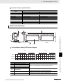
Tyco Electronics connectors
Model
3-1473562-4
1-1473562-4
1473562-4
2-1473562-4
4-1473562-4
Housing color
Orange
Red
Yellow
Blue
Green
Applicable wire range
Sheath diameter: 0.6 to 0.9 mm
Sheath diameter: 0.9 to 1.0 mm
Cross-sectional area: 0.08 to
Sheath diameter: 1.0 to 1.15 mm
0.5 mm2
Sheath diameter: 1.15 to 1.35 mm
Sheath diameter: 1.35 to 1.60 mm
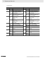
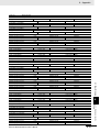
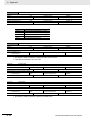
Model
Housing color
Applicable wire range
37104-3101-000FL Red
AWG26 (0.14mm2) to AWG24 (0.2mm2)
Sheath diameter: 0.8 to 1.0 mm
37104-3122-000FL Yellow
AWG26 (0.14mm2) to AWG24 (0.2mm2)
Sheath diameter: 1.0 to 1.2 mm
37104-3163-000FL Orange
AWG26 (0.14mm2) to AWG24 (0.2mm2)
Sheath diameter: 1.2 to 1.6 mm
37104-2124-000FL Green
AWG22 (0.3mm2) to AWG20 (0.5mm2)
Sheath diameter: 1.0 to 1.2 mm
2)
(0.5mm2)
37104-2165-000FL Blue
AWG22 (0.3mm to AWG20
Sheath diameter: 1.2 to 1.6 mm
37104-2206-000FL Gray
AWG22 (0.3mm2) to AWG20 (0.5mm2)
Sheath diameter: 1.6 to 2.0 mm
4
4-4-2 Connecting to e-CON Connector Terminals
Sumitomo 3M connectors
4-4 Connecting an External Device
Checking the e-CON connector and cable wire size
Clause title
Indicates the chapter title
of the current page.
Indexes
Indicates the chapter number
of the current page.
Section title
Indicates the section title
of the current page.
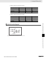
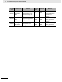
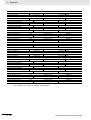
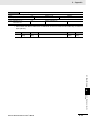
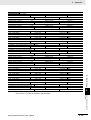
Panasonic Electric Works connectors
Model
AXF12142
AXF12146
Housing color
Applicable wire range
Red
AWG22 (0.3mm2) to AWG20 (0.5mm2)
Sheath diameter: 1.2 to 2.0 mm
Yellow
AWG28 (0.08mm2) to AWG24 (0.2mm2)
Sheath diameter: 0.7 to 1.2 mm
OMRON connectors
Model
XN2A-1430
Name of manuals
2
Specification
Spring
clamp type
GX-series EtherCAT Slave Unit User’s Manual
Applicable wire range
AWG28 (0.08mm2) to AWG20 (0.5mm2)
Sheath diameter: 1.5 mm max.
4 - 11
GX-series EtherCAT Slave Unit User’s Manual
Icon
The meanings of the icons used in this manual are as follows.
Precautions for Safe Use
Indicates precautions on what to do and what not to do to ensure using the product safely.
Precautions for Correct Use
Indicates precautions on what to do and what not to do to ensure proper operation and
performance.
Reference
This explains useful tips and reference information when using the product.
GX-series EtherCAT Slave Unit User’s Manual
3
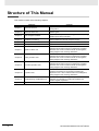
Structure of This Manual
This manual consists of the following chapters.
Chapters
4
Chapter 1
EtherCAT Network
Chapter 2
EtherCAT Slave Unit
Chapter 3
Basic Usage Procedures
Chapter 4
Installation and Wiring
Chapter 5
Chapter 6
EtherCAT Communications
Basic Specifications of Slave Units
Chapter 7
Digital I/O Slave Unit
Chapter 8
Analog I/O Slave Unit
Chapter 9
Encoder Input Slave Unit
Chapter 10
Expansion Unit
Chapter 11
Troubleshooting and Maintenance
Appendix
Appendix
Contents
Explains about the EtherCAT features and the network
configuration.
Overviews the GX-series EtherCAT Slave Unit and its
various types.
Explains the setup method and usage procedures by using
simple system setup examples.
Explains how to install Slave Units, and how to connect and
wire the EtherCAT network and power supply.
Explains the details of EtherCAT communications.
Explains the common specifications for all Slave Units.
Gives an overview about the Digital I/O Slave Unit and
explains names and functions of components consisting
the Slave Unit. It also contains internal circuit diagrams,
wiring diagrams and mounting dimensions.
Gives an overview about the Analog I/O Slave Unit and
explains names and functions of components consisting
the Slave Unit. It also contains internal circuit diagrams,
wiring diagrams and mounting dimensions.
Gives an overview about the Encoder Input Slave Unit and
explains names and functions of components consisting
the Slave Unit. It also contains internal circuit diagrams,
wiring diagrams and mounting dimensions.
Gives an overview about the Expansion Unit and explains
names and functions of components consisting the
Expansion Unit. It also contains internal circuit diagrams,
wiring diagrams and mounting dimensions.
This contains troubleshooting and inspection methods
intended for individuals to handle abnormalities and
conduct regular inspections.
Contains the object overview and explains the precautions.
GX-series EtherCAT Slave Unit User’s Manual
Terms and Conditions Agreement
Read and understand this Manual
Please read and understand this catalog before purchasing the products. Please consult your OMRON
representative if you have any questions or comments.
Warranty, Limitations of Liability
Warranties
z Exclusive Warranty
Omron’s exclusive warranty is that the Products will be free from defects in materials and
workmanship for a period of twelve months from the date of sale by Omron (or such other period
expressed in writing by Omron). Omron disclaims all other warranties, express or implied.
z Limitations
OMRON MAKES NO WARRANTY OR REPRESENTATION, EXPRESS OR IMPLIED, ABOUT
NON-INFRINGEMENT, MERCHANTABILITY OR FITNESS FOR A PARTICULAR PURPOSE OF
THE PRODUCTS. BUYER ACKNOWLEDGES THAT IT ALONE HAS DETERMINED THAT THE
PRODUCTS WILL SUITABLY MEET THE REQUIREMENTS OF THEIR INTENDED USE.
Omron further disclaims all warranties and responsibility of any type for claims or expenses based
on infringement by the Products or otherwise of any intellectual property right.
z Buyer Remedy
Omron’s sole obligation hereunder shall be, at Omron’s election, to (i) replace (in the form originally
shipped with Buyer responsible for labor charges for removal or replacement thereof) the
non-complying Product, (ii) repair the non-complying Product, or (iii) repay or credit Buyer an
amount equal to the purchase price of the non-complying Product; provided that in no event shall
Omron be responsible for warranty, repair, indemnity or any other claims or expenses regarding the
Products unless Omron’s analysis confirms that the Products were properly handled, stored,
installed and maintained and not subject to contamination, abuse, misuse or inappropriate
modification. Return of any Products by Buyer must be approved in writing by Omron before
shipment. Omron Companies shall not be liable for the suitability or unsuitability or the results from
the use of Products in combination with any electrical or electronic components, circuits, system
assemblies or any other materials or substances or environments. Any advice, recommendations or
information given orally or in writing, are not to be construed as an amendment or addition to the
above warranty.
See http://www.omron.com/global/ or contact your Omron representative for published information.
Limitation on Liability; Etc
OMRON COMPANIES SHALL NOT BE LIABLE FOR SPECIAL, INDIRECT, INCIDENTAL, OR
CONSEQUENTIAL DAMAGES, LOSS OF PROFITS OR PRODUCTION OR COMMERCIAL LOSS IN
ANY WAY CONNECTED WITH THE PRODUCTS, WHETHER SUCH CLAIM IS BASED IN
CONTRACT, WARRANTY, NEGLIGENCE OR STRICT LIABILITY.
GX-series EtherCAT Slave Unit User’s Manual
5
Further, in no event shall liability of Omron Companies exceed the individual price of the Product on
which liability is asserted.
Application Considerations
Suitability of Use
Omron Companies shall not be responsible for conformity with any standards, codes or regulations
which apply to the combination of the Product in the Buyer’s application or use of the Product. At
Buyer’s request, Omron will provide applicable third party certification documents identifying ratings
and limitations of use which apply to the Product. This information by itself is not sufficient for a
complete determination of the suitability of the Product in combination with the end product, machine,
system, or other application or use. Buyer shall be solely responsible for determining appropriateness
of the particular Product with respect to Buyer’s application, product or system. Buyer shall take
application responsibility in all cases.
NEVER USE THE PRODUCT FOR AN APPLICATION INVOLVING SERIOUS RISK TO LIFE OR
PROPERTY WITHOUT ENSURING THAT THE SYSTEM AS A WHOLE HAS BEEN DESIGNED TO
ADDRESS THE RISKS, AND THAT THE OMRON PRODUCT(S) IS PROPERLY RATED AND
INSTALLED FOR THE INTENDED USE WITHIN THE OVERALL EQUIPMENT OR SYSTEM.
Programmable Products
Omron Companies shall not be responsible for the user’s programming of a programmable Product, or
any consequence thereof.
Disclaimers
Performance Data
Data presented in Omron Company websites, catalogs and other materials is provided as a guide for
the user in determining suitability and does not constitute a warranty. It may represent the result of
Omron’s test conditions, and the user must correlate it to actual application requirements. Actual
performance is subject to the Omron’s Warranty and Limitations of Liability.
Change in Specifications
Product specifications and accessories may be changed at any time based on improvements and other
reasons. It is our practice to change part numbers when published ratings or features are changed, or
when significant construction changes are made. However, some specifications of the Product may be
changed without any notice. When in doubt, special part numbers may be assigned to fix or establish
key specifications for your application. Please consult with your Omron’s representative at any time to
confirm actual specifications of purchased Product.
Errors and Omissions
Information presented by Omron Companies has been checked and is believed to be accurate;
however, no responsibility is assumed for clerical, typographical or proofreading errors or omissions.
6
GX-series EtherCAT Slave Unit User’s Manual
Safety Precautions
Labels and Meanings to Ensure Safe Usage
To ensure safe usage of the EtherCAT Slave Unit, the precautions in this manual are displayed with the
following labels and symbols.
The precautions explained in this section describe important information regarding safety. These
precautions must be followed without fail.
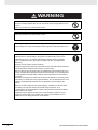
WARNING
Indicates a potentially hazardous
situation which, if not avoided, could
result in death or serious injury.
Additionally, there may be severe
property damage.
Caution
Indicates a potentially hazardous
situation which, if not avoided, may
result in minor or moderate injury, or
property damage.
Symbols
This symbol indicates a prohibited item (an item you must not
do).
The specific instruction is indicated using text inside the
.
The symbol shown to the left indicates "disassembly prohibited".
This symbol indicates caution (warnings included).
The specific instruction is indicated using text inside the
The symbol shown to the left indicates "typical cautions".
.
This symbol means it is a compulsory item (an item that must
be done).
The specific instruction is indicated using text inside the
.
The symbol shown to the left indicates "typical compulsory
items".
GX-series EtherCAT Slave Unit User’s Manual
7
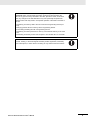
WARNING
Do not attempt to take any Unit apart and do not touch the interior of any Unit while
the power is being supplied. Also, do not turn ON the power supply while the cover
is open.
Doing any of these may result in electric shock.
Do not attempt to disassemble, repair, or modify any Units.
Doing any of these may result in electric shock.
Do not input voltages or currents exceeding the rated range to the Unit.
Using voltages or currents exceeding the rated range may cause Unit failure or fire.
Provide safety measures in external circuits (i.e., not in the Units), including the
following items, to ensure safety in the system if an abnormality occurs due to
malfunction of the PLC or another external factor affecting the PLC operation.
("PLC" includes CPU Units, other Units mounted in the PLC, and Remote I/O
Terminals.)
Not doing so may result in serious accidents.
Emergency stop circuits, interlock circuits, limit circuits, and similar safety measures
must be provided in external control circuits, not in the Units.
The PLC will turn OFF all outputs when its self-diagnosis function detects any error
or when a severe failure alarm (FALS) instruction is executed. As a countermeasure
for such problems, external safety measures must be provided to ensure safety in
the system.
The Slave Unit outputs may remain ON or OFF due to deposits on or burning of the
output relays, or destruction of the output transistors. As a countermeasure for such
problems, external safety measures must be provided to ensure safety in the
system.
When the 24-VDC output (service power supply) is overloaded or short-circuited,
the voltage may drop and result in the outputs being turned OFF. As a
countermeasure for such problems, external safety measures must be provided to
ensure safety in the system.
Implement proper measures as part of your communications system or in your
program to ensure safety in the system even when a communications error or
malfunction occurs during remote I/O communication.
8
GX-series EtherCAT Slave Unit User’s Manual
The CPU Unit refreshes I/O even when the program is stopped (i.e., even in
PROGRAM mode). Confirm safety thoroughly in advance before changing the
status of any part of memory allocated to I/O Units, Special I/O Units, or CPU Bus
Units. Any changes to the data allocated to any Unit specifically the Special I/O
Units/CPU Bus Units may result in unexpected operation of the loads connected to
the Unit.
• Transferring I/O memory data to the CPU Unit with a Programming Device (PC
tool).
• Changing present values in memory with a Programming Device.
• Force-setting/-resetting bits with a Programming Device.
• Transferring I/O memory files from a memory card or EM file memory to the CPU
Unit.
• Transferring I/O memory from a host computer or from another PLC on a network.
Fail-safe measures must be taken by the customer to ensure safety in the event of
incorrect, missing, or abnormal signals caused by broken signal lines, momentary
power interruptions, or other causes. Not doing so may result in serious accidents.
GX-series EtherCAT Slave Unit User’s Manual
9
Precautions for Safe Use
Observe the following precautions when using the Unit.
z Power Supply
• Always use the power supply voltage specified in this manual. An incorrect voltage may result in
malfunction or burning.
• Take appropriate measures to ensure that the specified power with the rated voltage and
frequency is supplied. Be particularly careful in places where the power supply is unstable. An
incorrect power supply may result in malfunction.
• Always turn OFF the power supply to the PLC, Slave Units and other Units before attempting any
of the following. Not turning OFF the power supply may result in malfunction or electric shock.
• Assembling any Units (Expansion Units).
• Removing or attaching the terminal blocks or connectors to Slave Unit.
• Replacing parts (e.g., relays).
• Setting the DIP switch or the node address switches
• Connecting cables or wiring the system.
z Installation
• Before touching a Unit, be sure to first touch a grounded metallic object in order to discharge any
static build-up. Not doing so may result in malfunction or damage.
• Make sure that the terminal blocks, communications cables, and other items with locking devices
are properly locked into place. Improver locking may result in malfunction.
• Mount the Units securely using DIN track.
• Make sure that all Slave Unit mounting screws and cable connector screws are tightened to the
torque specified in this manual. Incorrect tightening torque may result in malfunction.
• Make sure that all terminal block screws are tightened to the torque specified in this manuals.
Incorrect tightening torque may result in fire, malfunction, or failure.
• Always use the specified communications cables and connectors.
• Do not extend connection distances or the number of connected nodes beyond the ranges given
in the specifications.
• When there are multiple systems, keep the cables unbundled and separated by at least 5 mm to
prevent unstable operation due to interference.
z Wiring
•
•
•
•
•
Turn the power on after checking that the wiring and switch settings are correct.
Use the correct wire tools to wire the Unit.
Confirm the polarity of all terminals before wiring them.
Do not allow foreign matter to enter the Units when wiring and installing the Units.
Observe the following precautions when wiring the communications cable.
• Separate the communications cables from the power lines or high-tension lines.
• Do not bend the communications cables past their natural bending radius.
• Do not pull on the communications cables.
• Do not place heavy objects on top of the communications cables.
• Always lay communications cable inside ducts.
• Turn OFF the power of PLC and all the Slave Units before wiring the communication cables.
• Do not apply voltages to the Input Slave Units in excess of the rated input voltage. Excess voltage
or loads may result in burning.
10
GX-series EtherCAT Slave Unit User’s Manual
• Do not apply voltages or connect loads to the Outputs Slave Units in excess of the maximum
switching capacity. Excess voltage or loads may result in burning.
z Handling
• When transporting the product, use special packing boxes, and protect it from being exposed to
excessive vibration or impact during transportation.
• Do not bend cables past their natural bending radius or pull on cables.
• After replacing Units, resume operation only after transferring to the new CPU Unit and/or Special
I/O Units the contents of the DM Area, HR Area, and other data required for resuming operation.
Not doing so may result in unexpected operation.
• Check the user program for proper execution before actually running it on the Unit. Not checking
the program may result in unexpected operation.
• When replacing relays or other parts, be sure to confirm that the ratings of the new part are
correct. Not doing so may result in malfunction or burning.
• Confirm that no adverse effect will occur in the system before attempting any of the following.
• Changing the operating mode of the PLC.
• Setting/resetting any bit in memory.
• Changing the present value of any word or any set value in memory.
• Do not use thinner when cleaning. Use commercially available alcohol.
z External Circuits
• Install external breakers and take other safety measures against short-circuiting in external wiring.
GX-series EtherCAT Slave Unit User’s Manual
11
Precautions for Correct Use
• Wire all connections correctly according to instructions in this manual.
Failure to install them may result in serious accidents.
• Do not operate the control system in the following locations:
• Location subject to direct sunlight.
• Locations subject to temperatures or humidity outside the range specified in the specifications.
• Locations subject to condensation as the result of severe changes in temperature.
• Location subject to corrosive or flammable gases.
• Location subject to dust (especially iron dust) or salts.
• Location subject to exposure to water, acid, oil, chemicals, etc.
• Locations subject to shock or vibration.
• Confirm voltage specifications when wiring communications, the power supply, and I/O crossovers.
Incorrect wire may result in malfunction.
• Wire all connections correctly according to instructions in this manual.
• Use the correct wiring materials to wire the Unit.
• Take appropriate and sufficient countermeasures when installing systems in the following locations:
• Locations subject to static electricity or other forms of noise.
• Locations subject to strong electromagnetic fields.
• Locations subject to possible exposure to radioactivity.
• Locations close to power supplies.
• Do not drop any Unit or subject any Unit to excessive shock or vibration. Otherwise, Unit failure or
malfunction may occur.
12
GX-series EtherCAT Slave Unit User’s Manual
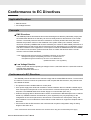
Conformance to EC Directives
Applicable Directives
• EMC Directives
• Low Voltage Directive
Concepts
z EMC Directives
The OMRON products described in this manual are designed so that they individually comply with
the related EMC Directives so that they can be more easily built into other devices or the overall
machine. The actual products have been checked for conformity to EMC Directives (See note)*.
Whether the products conform to the standards in the system used by the customer, however,
cannot be checked by OMRON and must be checked by the customer. EMC-related performance of
the OMRON devices that comply with EC Directives will vary depending on the configuration, wiring,
and other conditions of the equipment or control panel on which the OMRON devices are installed.
The customer must, therefore, perform the final check to confirm that devices and the overall
machine conform to EMC standards.
* Note: Applicable EMC (Electromagnetic Compatibility) standards are as follows:
EMS (Electromagnetic Susceptibility): EN 61131-2 and EN 61000-6-2
EMI (Electromagnetic Interference): EN 61131-2 and EN61000-6-4
(Radiated emission: 10-m regulations)
z Low Voltage Directive
Always ensure that devices operating at voltages of 50 to 1,000 VAC and 75 to 1,500 VDC meet the
required safety standards.
Applicable standard: EN 61131-2
Conformance to EC Directives
The OMRON products described in this manual comply with the related EMC Directives. To ensure that
the machine or device in which the products are used complies with EC Directives, the products must
be installed as follows:
• The products must be installed within a control panel.
• A DC power supply with reinforced insulation or double insulation that can maintain a stable output
even if the input is interrupted for 10 ms must be used for communications power, internal power, and
I/O power. The OMRON S8JX-series Power Supply is recommended. (See note.)*
• Products complying with EC Directives also conform to the Emission Standards (EN 61131-2 and EN
61000-6-4). Radiated emission characteristics (10-m regulations) may vary depending on the
configuration of the control panel used, other devices connected to the control panel, wiring, and
other conditions. You must therefore confirm that the overall machine or equipment complies with EC
Directives.
• Conformance with the EC Directives was confirmed with a system configuration using I/O wiring
lengths of less than 30 m.
* Note: Conformance with the EMC Directive was confirmed when using the recommended power supply.
GX-series EtherCAT Slave Unit User’s Manual
13
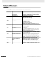
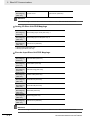
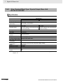
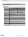
Related Manuals
The following manuals also deal with EtherCAT. Refer to them for details.
Man No.
W487
W446
14
Name of manuals
CJ Series
Position Control Units
Operation Manual
CX-Programmer
Operation Manual
W500
NJ-series CPU Unit Hardware
User’s Manual
W501
NJ-series CPU Unit Software
User’s Manual
W505
NJ-series CPU Unit Built-in
EtherCAT® Port User’s Manual
W503
NJ-series Troubleshooting
Manual
W504
Sysmac Studio Version 1
Operation Manual
Contents
Explains the setup and operation procedures of the
EtherCAT Position Control Units (CJ1W-NCx81/x82) which
functions as a master.
Explains the operations method of the Windows-based
programming tool CX-Programmer.
Explains the overall NJ-series System and the following
items for the NJ501 CPU Units.
• Features and system configuration
• Overview
• Part names and functions
• General specifications
• Installation and wiring
• Maintenance and inspection
Use this manual together with the NJ-series CPU Unit
Software User’s Manual (Cat. No. W501).
Explains the following items for NJ-series CPU Units.
• CPU Unit operation
• CPU Unit functions
• Initial settings
• Languages and programming based on IEC 61131-3.
Use this manual together with the NJ-series CPU Unit
Hardware User’s Manual (Cat. No. W500).
Explains the built-in EtherCAT port.
An overview is provided and the configuration, functions,
and setup are described.
Use this manual together with the NJ-series CPU Unit
Hardware User’s Manual (Cat. No. W500) and the
NJ-series CPU Unit Software User’s Manual (Cat. No.
W501).
Explains error management concepts and the individual
errors that are detected by the NJ-series System.
Use this manual together with the NJ-series CPU Unit
Hardware User’s Manual (Cat. No. W500) and the
NJ-series CPU Unit Software User’s Manual (Cat. No.
W501).
Explains the operating procedures of the Sysmac Studio.
GX-series EtherCAT Slave Unit User’s Manual
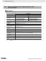
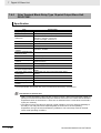
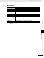
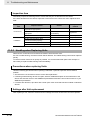
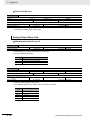
Version Upgrade Information
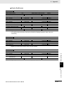
The following changes have been made in the upgrade from unit version 1.0 to 1.1 of the GX-series
EtherCAT Slave Units.
Item
Emergency message setting when the Slave Unit’s
power supply is turned ON
Sysmac error status
Saving node address settings
Displaying the serial number
Sysmac device
Conformance to ESI
functions
specifications (ETG.2000 S (R)
V1.0.1)
SII data checking
Data attribute for Input Time Constant (3000 hex) for
Digital I/O Slave Unit
Bit objects
• Digital I/O bit objects for Digital I/O Slave Units (3020
hex and 3220 hex)
• Soft switches (bits) and status (bits) objects for
Encoder Input Slave Units (4021 hex and 4031 hex)
GX-series EtherCAT Slave Unit User’s Manual
Unit version 1.0
Emergency message
notification is enabled at
startup.
Not supported.
Not supported.
Not supported.
Unit version 1.1
Emergency message
notification is not enabled
at startup.
Supported.
Supported.
Supported.
Supported.
Supported.
Not supported.
Supported.
Attribute: R
Attribute: D
Not supported.
Supported.
15
Contents
Introduction............................................................................................................................... 1
Intended Readers........................................................................................................... 1
How to Read the Manual .......................................................................................................... 2
Page Structure................................................................................................................ 2
Icon................................................................................................................................. 3
Structure of This Manual.......................................................................................................... 4
Terms and Conditions Agreement .......................................................................................... 5
Read and understand this Manual ................................................................................. 5
Warranty, Limitations of Liability ..................................................................................... 5
Application Considerations............................................................................................. 6
Safety Precautions ................................................................................................................... 7
Labels and Meanings to Ensure Safe Usage ................................................................. 7
Symbols.......................................................................................................................... 7
Precautions for Safe Use ....................................................................................................... 10
Precautions for Correct Use .................................................................................................. 12
Conformance to EC Directives .............................................................................................. 13
Applicable Directives .................................................................................................... 13
Concepts ...................................................................................................................... 13
Conformance to EC Directives ..................................................................................... 13
Related Manuals ..................................................................................................................... 14
Version Upgrade Information ................................................................................................ 15
Chapter 1
1-1
Overview of EtherCAT Networks.......................................................................................... 1-2
1-1-1 Features of EtherCAT.................................................................................................. 1-2
1-1-2 Structure of EtherCAT ................................................................................................. 1-2
1-1-3 Communications types of EtherCAT ........................................................................... 1-4
1-1-4 Connection Examples of EtherCAT ............................................................................. 1-5
1-2
Configuration Elements of EtherCAT Network ................................................................... 1-6
1-2-1 Configuration Devices of EtherCAT Network .............................................................. 1-6
1-2-2 Overview of Configuration Devices ............................................................................. 1-7
Chapter 2
EtherCAT Slave Unit.......................................................... 2-1
2-1
Overview of EtherCAT Slave Unit......................................................................................... 2-2
2-1-1 Slave Units Usage ....................................................................................................... 2-2
2-1-2 Features of GX-series EtherCAT Slave Units.............................................................. 2-2
2-2
Types of EtherCAT Slave Units ............................................................................................ 2-3
2-2-1 Slave Units List............................................................................................................ 2-3
2-2-2 Installation, I/O Connection, and Power Supply Methods for Each Slave Unit ........... 2-6
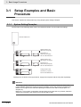
Chapter 3
3-1
16
EtherCAT Network............................................................. 1-1
Basic Usage Procedures .................................................. 3-1
Setup Examples and Basic Procedure ................................................................................ 3-2
3-1-1 System Setting Examples ........................................................................................... 3-2
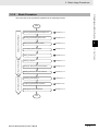
3-1-2 Basic Procedure .......................................................................................................... 3-3
GX-series EtherCAT Slave Unit User’s Manual
3-2
Setting and Wiring Hardware ............................................................................................... 3-4
3-2-1 Mounting and Setting EtherCAT Master Unit .............................................................. 3-4
3-2-2 Mounting and Setting Slave Units ............................................................................... 3-4
3-2-3 Wiring Communications Cables .................................................................................. 3-4
3-2-4 Connecting Power Supplies ........................................................................................ 3-4
3-2-5 Wiring I/O Devices....................................................................................................... 3-4
3-3
Starting Communications ..................................................................................................... 3-5
3-3-1 Starting a System ........................................................................................................ 3-5
3-3-2 Setting EtherCAT Communications............................................................................. 3-5
3-3-3 Starting EtherCAT Communications ............................................................................ 3-5
3-4
Checking Operations ............................................................................................................ 3-6
3-4-1 Checking Unit Displays ............................................................................................... 3-6
3-4-2 Confirming Data Read and Write ................................................................................ 3-6
3-4-3 Setting Slave Unit Parameter ...................................................................................... 3-6
Chapter 4
Installation and Wiring...................................................... 4-1
4-1
Mounting Slave Units ............................................................................................................ 4-2
4-1-1 Mounting Preparation .................................................................................................. 4-2
4-1-2 Mounting Direction ...................................................................................................... 4-2
4-1-3 Mounting Method......................................................................................................... 4-2
4-1-4 Removal Method ......................................................................................................... 4-3
4-2
Connecting to EtherCAT Network ........................................................................................ 4-4
4-2-1 Precautions for Network Connection........................................................................... 4-4
4-2-2 Preparation for Connecting Network ........................................................................... 4-5
4-2-3 Connecting Communications Cables and Connectors................................................ 4-6
4-2-4 Connecting to Communications Cables ...................................................................... 4-7
4-3
Connecting to Unit Power Supply and I/O Power Supply.................................................. 4-8
4-3-1 Precautions at Supplying Unit Power and I/O Power .................................................. 4-8
4-3-2 Unit Power Supply Specifications................................................................................ 4-9
4-3-3 Connecting the Unit Power Supply.............................................................................. 4-9
4-3-4 Connecting the I/O Power Supply ............................................................................. 4-10
4-4
Connecting an External Device.......................................................................................... 4-12
4-4-1 Connecting to a Screw Terminal Block...................................................................... 4-12
4-4-2 Connecting to e-CON Connector Terminals .............................................................. 4-13
Chapter 5
EtherCAT Communications.............................................. 5-1
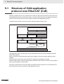
5-1
Structure of CAN application protocol over EtherCAT (CoE)............................................ 5-2
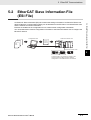
5-2
EtherCAT Slave Information File (ESI File) ......................................................................... 5-3
5-3
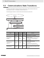
Communications State Transitions...................................................................................... 5-4
5-4
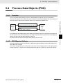
Process Data Objects (PDO)................................................................................................. 5-5
5-4-1 Overview ..................................................................................................................... 5-5
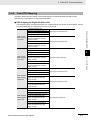
5-4-2 PDO Mapping Settings................................................................................................ 5-5
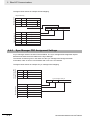
5-4-3 Sync Manager PDO Assignment Settings................................................................... 5-6
5-4-4 Fixed PDO Mapping .................................................................................................... 5-7
5-5
Service Data Object (SDO).................................................................................................... 5-9
5-5-1 Overview ..................................................................................................................... 5-9
5-5-2 Abort Codes ................................................................................................................ 5-9
5-6
EtherCAT Master Unit - Slave Unit Communications ....................................................... 5-10
5-6-1 FREE RUN Mode ...................................................................................................... 5-10
5-6-2 DC Mode ................................................................................................................... 5-10
GX-series EtherCAT Slave Unit User’s Manual
17
5-7
Emergency Messages ......................................................................................................... 5-12
5-7-1 Emergency Message Notification.............................................................................. 5-12
5-7-2 Diagnosis History ...................................................................................................... 5-12
5-8
Sysmac Device Functions .................................................................................................. 5-13
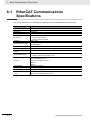
Chapter 6
6-1
EtherCAT Communications Specifications......................................................................... 6-2
6-2
General Specifications .......................................................................................................... 6-3
6-3
Specifications of Common Areas ........................................................................................ 6-4
6-3-1 Status Indicators.......................................................................................................... 6-4
6-3-2 Node Address Setting Switches .................................................................................. 6-6
6-3-3 Communications Connectors ...................................................................................... 6-7
6-3-4 Unit Power Supply Connector ..................................................................................... 6-7
6-3-5 I/O Power Supply Connector....................................................................................... 6-8
Chapter 7
Digital I/O Slave Unit ......................................................... 7-1
7-1
Digital I/O Slave Unit.............................................................................................................. 7-2
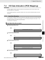
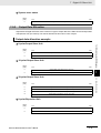
7-2
I/O Data Allocation (PDO Mapping)...................................................................................... 7-3
7-2-1 Input Data Allocation ................................................................................................... 7-3
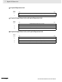
7-2-2 Output Data Allocation ................................................................................................ 7-5
7-3
Functions of Digital I/O Slave Units ..................................................................................... 7-7
7-3-1 Input Filter ................................................................................................................... 7-7
7-3-2 Error Mode Output....................................................................................................... 7-8
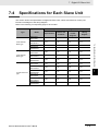
7-4
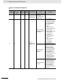
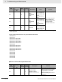
Specifications for Each Slave Unit....................................................................................... 7-9
7-4-1 2-tier Terminal Block Type 16-point Input Slave Unit GX-ID1611/ID1621 ................. 7-10
7-4-2 2-tier Terminal Block Type 16-point Output Slave Unit GX-OD1611/OD1621 ........... 7-14
7-4-3 2-tier Terminal Block Relay Type 16-point Output Slave Unit GX-OC1601............... 7-18
7-4-4 2-tier Terminal Block Type 8-point Input and 8-point Output Slave Unit
GX-MD1611/MD1621 ................................................................................................ 7-22
7-4-5 3-tier Terminal Block Type 16-point Input Slave Unit GX-ID1612/ID1622 ................. 7-28
7-4-6 3-tier Terminal Block Type 16-point Output Slave Unit GX-OD1612/OD1622........... 7-33
7-4-7 3-tier Terminal Block Type 8-point Input and 8-point Output Slave Unit
GX-MD1612/MD1622................................................................................................ 7-38
7-4-8 e-CON Connector Type 16-point Input Slave Unit GX-ID1618/ID1628..................... 7-44
7-4-9 e-CON Connector Type 16-point Output Slave Unit GX-OD1618/OD1628 .............. 7-48
7-4-10 e-CON Connector Type 8-point Input and 8-point Output Slave Unit
GX-MD1618/MD1628................................................................................................ 7-53
7-4-11 e-CON Connector Type 32-point Input Slave Unit GX-ID3218/ID3228..................... 7-59
7-4-12 e-CON Connector Type 32-point Output Slave Unit GX-OD3218/OD3228 .............. 7-64
7-4-13 e-CON Connector Type 16-point Input and 16-point Output Slave Unit
GX-MD3218/MD3228................................................................................................ 7-69
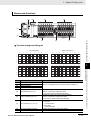
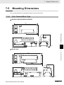
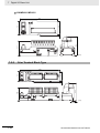
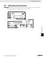
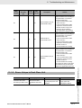
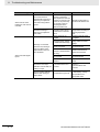
7-5
Mounting Dimensions ......................................................................................................... 7-75
7-5-1 2-tier Terminal Block Type ......................................................................................... 7-75
7-5-2 3-tier Terminal Block Type ......................................................................................... 7-76
7-5-3 e-CON Connector Type............................................................................................. 7-77
Chapter 8
8-1
18
Basic Specifications of Slave Units................................. 6-1
Analog I/O Slave Unit........................................................ 8-1
Analog I/O Slave Unit ............................................................................................................ 8-2
GX-series EtherCAT Slave Unit User’s Manual
8-2
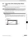
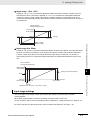
Overview of the Analog Input Slave Unit ............................................................................ 8-3
8-2-1 Input Range and Converted Data................................................................................ 8-3
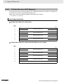
8-2-2 I/O Data Allocation (PDO Mapping) ............................................................................ 8-6
8-3
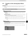
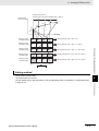
Function of the Analog Input Slave Unit ............................................................................. 8-7
8-3-1 AD Conversion Available Point Setting ....................................................................... 8-7
8-3-2 Moving Average .......................................................................................................... 8-8
8-3-3 Disconnected Line Detection..................................................................................... 8-10
8-3-4 User adjustment ........................................................................................................ 8-10
8-4
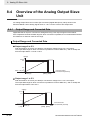
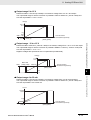
Overview of the Analog Output Slave Unit ....................................................................... 8-12
8-4-1 Output Range and Converted Data........................................................................... 8-12
8-4-2 I/O Data Allocation (PDO Mapping) .......................................................................... 8-14
8-5
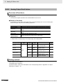
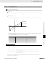
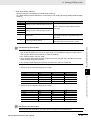
Function of the Analog Output Slave Unit ........................................................................ 8-15
8-5-1 DA Conversion Available Point Setting ..................................................................... 8-15
8-5-2 Analog Output Fault Action ....................................................................................... 8-16
8-5-3 User Adjustment........................................................................................................ 8-17
8-6
Overview of Each Slave Unit Type ..................................................................................... 8-18
8-6-1 4-point Input Slave Unit GX-AD0471......................................................................... 8-19
8-6-2 2-point Output Slave Unit GX-DA0271...................................................................... 8-23
8-7
Mounting Dimensions ......................................................................................................... 8-27
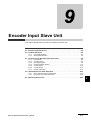
Chapter 9
Encoder Input Slave Unit.................................................. 9-1
9-1
Encoder Input Slave Unit ...................................................................................................... 9-2
9-2
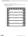
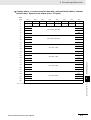
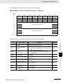
I/O Data Allocation................................................................................................................. 9-3
9-2-1 Input Data Allocation ................................................................................................... 9-3
9-2-2 Output Data Allocation ................................................................................................ 9-6
9-3
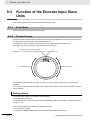
Function of the Encoder Input Slave Units ......................................................................... 9-8
9-3-1 Count Mode................................................................................................................. 9-8
9-3-2 Circular Counter .......................................................................................................... 9-8
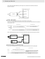
9-3-3 Input Signal Types....................................................................................................... 9-9
9-3-4 Encoder Direction Setting.......................................................................................... 9-11
9-3-5 Counter Reset ........................................................................................................... 9-12
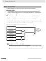
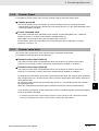
9-3-6 Counter Preset .......................................................................................................... 9-13
9-3-7 Counter value latch ................................................................................................... 9-13
9-4
Specifications for Each Slave Unit .................................................................................... 9-14
9-4-1 Open collector input type GX-EC0211 ...................................................................... 9-15
9-4-2 Line Driver Input Type GX-EC0241........................................................................... 9-23
9-5
Mounting Dimensions ......................................................................................................... 9-30
Chapter 10 Expansion Unit ................................................................ 10-1
10-1 Overview of the Expansion Unit......................................................................................... 10-2
10-1-1 Connecting Expansion Units ..................................................................................... 10-2
10-1-2 I/O Power Supply ...................................................................................................... 10-3
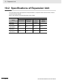
10-2 Specifications of Expansion Unit....................................................................................... 10-4
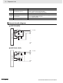
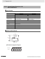
10-2-1 8-point Input Expansion Unit XWT-ID08/ID08-1........................................................ 10-5
10-2-2 8-point Output Expansion Unit XWT-OD08/OD08-1 ................................................. 10-8
10-2-3 16-point Input Expansion Unit XWT-ID16/ID16-1.................................................... 10-11
10-2-4 16-point Output Expansion Unit XWT-OD16/OD16-1 ............................................. 10-14
10-3 Mounting Dimensions ....................................................................................................... 10-17
GX-series EtherCAT Slave Unit User’s Manual
19
Chapter 11 Troubleshooting and Maintenance ................................ 11-1
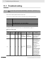
11-1 Troubleshooting .................................................................................................................. 11-2
11-1-1 Errors that Can be Checked with Status Indicator and Actions to Take .................... 11-2
11-1-2 Errors Unique to Each Slave Unit.............................................................................. 11-7
11-1-3 Error Notification Methods and Types ..................................................................... 11-13
11-1-4 Sysmac Error Status Codes .................................................................................... 11-14
11-1-5 Emergency Error Code............................................................................................ 11-19
11-1-6 Application Layer Status Codes .............................................................................. 11-21
11-2 Equipment Maintenance ................................................................................................... 11-23
11-2-1 Cleaning .................................................................................................................. 11-23
11-2-2 Inspections .............................................................................................................. 11-23
11-2-3 Handling when Replacing Units .............................................................................. 11-24
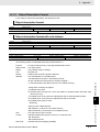
Chapter A Appendix............................................................................A-1
A-1 Object Dictionary ...................................................................................................................A-2
A-1-1 Object Dictionary Area ................................................................................................A-2
A-1-2 Data Types ..................................................................................................................A-2
A-1-3 Object Description Format...........................................................................................A-3
A-1-4 Communication Objects ..............................................................................................A-4
A-1-5 PDO Mapping Object ..................................................................................................A-8
A-1-6 Sync Manager Communication Object......................................................................A-21
A-1-7 Manufacturer Specific Objects...................................................................................A-25
A-2 Current Consumption Summary ........................................................................................A-46
A-2-1 Digital I/O Slave Unit .................................................................................................A-46
A-2-2 Analog I/O Slave Unit ................................................................................................A-46
A-2-3 Encoder Input Slave Unit...........................................................................................A-46
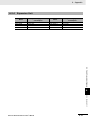
A-2-4 Expansion Unit ..........................................................................................................A-47
A-3 Precautions with Connecting Two-wire DC Sensors .......................................................A-48
A-3-1 Relation between ON Voltage of a Unit
with DC Inputs and Sensor Residual Voltage............................................................A-48
A-3-2 Relation between ON Current of a Unit with DC Inputs and Sensor Control Output.A-48
A-3-3 Relation between OFF Current of a Unit with DC Inputs
and Sensor Leakage Current ....................................................................................A-49
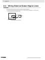
A-4 Wiring External Output Signal Lines .................................................................................A-50
A-5 I/O Power Supply Current ...................................................................................................A-51
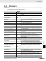
A-6 Glossary ...............................................................................................................................A-53
20
GX-series EtherCAT Slave Unit User’s Manual
1
EtherCAT Network
This chapter explains the overview of EtherCAT network.
1-1 Overview of EtherCAT Networks . . . . . . . . . . . . . . . . . . . . . . . . . . . . . . . . . 1-2
1-1-1
1-1-2
1-1-3
1-1-4
Features of EtherCAT . . . . . . . . . . . . . . . . . . . . . . . . . . . . . . . . . . . . . . . . . . . .
Structure of EtherCAT . . . . . . . . . . . . . . . . . . . . . . . . . . . . . . . . . . . . . . . . . . . .
Communications types of EtherCAT . . . . . . . . . . . . . . . . . . . . . . . . . . . . . . . . .
Connection Examples of EtherCAT . . . . . . . . . . . . . . . . . . . . . . . . . . . . . . . . .
1-2
1-2
1-4
1-5
1-2 Configuration Elements of EtherCAT Network . . . . . . . . . . . . . . . . . . . . . . 1-6
1-2-1
1-2-2
Configuration Devices of EtherCAT Network . . . . . . . . . . . . . . . . . . . . . . . . . . 1-6
Overview of Configuration Devices . . . . . . . . . . . . . . . . . . . . . . . . . . . . . . . . . . 1-7
GX-series EtherCAT Slave Unit User’s Manual
1-1
1 EtherCAT Network
1-1
Overview of EtherCAT Networks
EtherCAT (Ethernet Control Automation Technology) is a high-performance industrial network system
based on Ethernet system and can realize faster and more efficient communications.
Each node achieves a short communications cycle time by transmitting Ethernet frames at high speed.
Furthermore, even though EtherCAT is a unique protocol, it offers excellent general-purpose
applicability. For example, you can use Ethernet cables because EtherCAT utilizes standard Ethernet
technology for the physical layer. And the effectiveness of EtherCAT can be fully utilized not only in
large control systems that require high processing speeds and system integrity, but also in small and
medium control systems.
1-1-1
Features of EtherCAT
EtherCAT has the following features.
z Extremely high-speed communications with speed of 100 Mbps
It dramatically shortens the I/O response time from generation of input signals to transmission of
output signals. By fully utilizing the optimized Ethernet frame bandwidth to transfer data using a
high-speed repeat method, it is possible to efficiently transmit a wide variety of data.
z Extremely High Compatibility with Ethernet
EtherCAT is an open network with extremely high compatibility with conventional Ethernet systems.
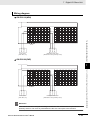
1-1-2
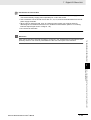
Structure of EtherCAT
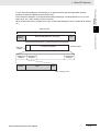
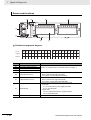
EtherCAT does not send data to individual slave nodes on the network, instead, it passes Ethernet
frames through all of the slave nodes.
When frame passes through a slave node, the slave node reads and writes data in the areas allocated
to it in the frames in a few nanoseconds.
Ethernet frames sent from the EtherCAT Master Unit go through all the EtherCAT Slave Units without
stopping on the way. Once they reach the final Slave Unit, they are sent back from the final Slave Unit,
pass through all Slave Units again, and return to the EtherCAT Master Unit.
With this structure, EtherCAT secures high-speed and real-time data transmission.
EtherCAT
Master Unit
Slave Unit
Slave Unit
Slave Unit
Data
OUT
IN
• Reading output data addressed to the local Slave Units
• Writing input data
Ethernet frame
1-2
GX-series EtherCAT Slave Unit User’s Manual
1 EtherCAT Network
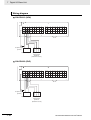
1
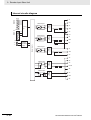
Ethernet frame
Ethernet data (Maximum 1498 bytes)
1st EtherCAT 2nd EtherCAT
datagram
datagram
Header
CRC
1...n EtherCAT datagram
EtherCAT
header
Data
.....
1-1-2 Structure of EtherCAT
Ethernet
header
EtherCAT frame
n th EtherCAT
datagram
WKC
WKC : Working counter
GX-series EtherCAT Slave Unit User’s Manual
1-1 Overview of EtherCAT
Networks
It is the "EtherCAT datagram" stored directly in an Ethernet frame that exchanges data regularly
between the EtherCAT Master Unit and Slave Units.
Each "EtherCAT datagram" is configured with header (data length, including address of one or more
Slave Units, etc.), data, working counter (check bit).
When an Ethernet frame is compared to a "train", an EtherCAT datagram can be considered as "railway
car."
1-3
1 EtherCAT Network
1-1-3
Communications types of EtherCAT
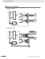
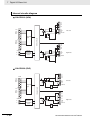
EtherCAT provides the following two types of communication functions.
PDO communications are always updating data per communication cycle on EtherCAT, while SDO
communications are processed in between those updates.
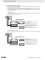
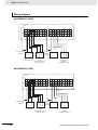
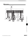
Process data communications functions (PDO communications)
This communication function is used to transfer process data in real time in a fixed-cycle.
By mapping logical process data space to each node by the EtherCAT Master Unit, it achieves
fixed-cycle communications among the EtherCAT Master Unit and Slave Units.
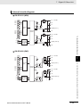
EtherCAT Master Unit
Slave Unit
Slave Unit
Slave Unit
Slave Unit
Ethernet frame
Ethernet
header
EtherCAT
header
1st EtherCAT
datagram
2nd EtherCAT
datagram
3rd EtherCAT
datagram
. . .
CRC
Logic process data
.
.
.
Data a
.
.
.
Data b
Data c
.
.
.
Mailbox communications functions (SDO communications)
It refers to message communications.
At any timing, the EtherCAT Master Unit transmits commands to Slave Units and the Slave Units return
responses to the EtherCAT Master Unit.
It performs the following data communications:
• Read and write process data
• Make Slave Unit setting
• Monitor Slave Unit state
1-4
GX-series EtherCAT Slave Unit User’s Manual
1 EtherCAT Network
1-1 Overview of EtherCAT
Networks
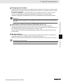
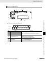
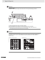
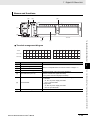
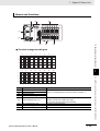
1-1-4
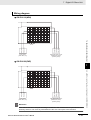
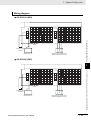
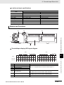
Connection Examples of EtherCAT
This section explains the connection examples of EtherCAT network.
EtherCAT Master Unit
ID211
0 1 2 3 4 5 6 7
8 9 10 11 12 13 14 15
1
AD042
RUN
ERC
ERH
B1
A1
0
1
2
x10 1
78
901
No.
456
MACH
23
3
4
1-1-4 Connection Examples of EtherCAT
5
456
23
7
x10 0
901
78
6
8
9
10
11
12
13
14
15
COM
DC24V
7mA
Digital I/O Slave Unit
Servo Drive
ADR
ADR
ADR
Servomotor
Inverter
GX-series EtherCAT Slave Unit User’s Manual
1-5
1 EtherCAT Network
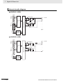
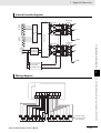
1-2
Configuration Elements of EtherCAT
Network
This section explains the configuration devices and usages of EtherCAT network.
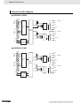
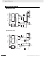
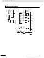
1-2-1
Configuration Devices of EtherCAT Network
The devices composing an EtherCAT network are shown in the figure below.
EtherCAT Master Unit
ID211
PC
(Configuration Tool)
0 1 2 3 4 5 6 7
8 9 10 11 12 13 14 15
AD042
RUN
ERC
ERH
B1
A1
0
1
2
x10
1
78
901
No.
456
MACH
23
3
4
5
456
x10 0
23
7
901
78
6
8
9
10
11
12
13
14
15
COM
DC24V
7mA
RS-232C port connection
Peripheral port connection
ESI file
I/O power supply
Communications cable
Unit power supply
Analog I/O Slave Unit
Digital I/O Slave Unit
ADR
ADR
ADR
Communications Unit
Servo Drive
1-6
Inverter
GX-series EtherCAT Slave Unit User’s Manual
1 EtherCAT Network
1-2 Configuration Elements of
EtherCAT Network
1-2-2
Overview of Configuration Devices
The overview of each configuration device is as follows:
EtherCAT Master Unit
Administers the EtherCAT network, monitors the state of Slave Units, exchanges I/O data with Slave
Units.
Outputs data received from the EtherCAT Master Unit through the EtherCAT network, or sends input
data to the EtherCAT Slave Unit through the EtherCAT network.
There are Digital I/O Slave Unit and Analog I/O Slave Unit.
Communications Unit
By mounting to an inverter and other devices, it is possible to serve as a Slave Unit in the EtherCAT
network.
Configuration Tool
It is a PC software for making setting of the EtherCAT network and each Slave Unit.
It can be used either by connecting to the EtherCAT Master Unit or as a substitute of the EtherCAT
Master Unit.
Communications cable
Uses cables of Ethernet category 5 (100BASE-TX) or higher, with double-shield (aluminum tape and
braided shielding), which are connected straight.
ESI (EtherCAT Slave Information) file
Describes information specific to EtherCAT Slave Units in XML format.
By reading this file into the Configuration Tool, it is possible to perform various settings such as
mapping of Slave Units to I/O memory easily.
Unit power supply
Provides power for communications of each Slave Unit and internal operations.
Separate them from the I/O power supply when wiring.
I/O power supply
Provides power for input/output operations of external devices connected to Slave Units.
Separate from Unit power supply when wiring.
GX-series EtherCAT Slave Unit User’s Manual
1-7
1-2-2 Overview of Configuration Devices
EtherCAT Slave Unit
1
1 EtherCAT Network
1-8
GX-series EtherCAT Slave Unit User’s Manual
2
EtherCAT Slave Unit
This chapter explains the overview of EtherCAT Slave Unit.
2-1 Overview of EtherCAT Slave Unit . . . . . . . . . . . . . . . . . . . . . . . . . . . . . . . . . 2-2
2-1-1
2-1-2
Slave Units Usage . . . . . . . . . . . . . . . . . . . . . . . . . . . . . . . . . . . . . . . . . . . . . . 2-2
Features of GX-series EtherCAT Slave Units . . . . . . . . . . . . . . . . . . . . . . . . . . 2-2
2-2 Types of EtherCAT Slave Units . . . . . . . . . . . . . . . . . . . . . . . . . . . . . . . . . . . 2-3
2-2-1
2-2-2
Slave Units List . . . . . . . . . . . . . . . . . . . . . . . . . . . . . . . . . . . . . . . . . . . . . . . . . 2-3
Installation, I/O Connection, and Power Supply Methods for Each Slave Unit . 2-6
GX-series EtherCAT Slave Unit User’s Manual
2-1
2 EtherCAT Slave Unit
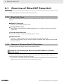
2-1
Overview of EtherCAT Slave Unit
This section explains the overview of EtherCAT Slave Unit.
2-1-1
Slave Units Usage
Slave Units supported by this manual are largely classified into the following types by the their intended
purposes.
z Digital I/O Slave Unit
Inputs and outputs digital ON/OFF signals.
z Analog I/O Slave Unit
Performs AD or DA conversion for analog signals of 0 to 5 V, 4 to 20 mA, and so on and inputs or
outputs them.
z Encoder Input Slave Unit
Performs conversion for pulse input signals from an encoder.
z Expansion Unit
Mounted on a Digital I/O Slave Unit in order to expand the number of I/O points.
Note, however, Expansion Units can only be mounted on Digital I/O Slave Units with 2-tier terminal
block and 16 points.
2-1-2
Features of GX-series EtherCAT Slave Units
The GX-series EtherCAT Slave Units have the following features.
Optimum Functionality and Ease of Operation Based on Unified
Specifications
The GX-series EtherCAT Slave Units are Sysmac devices.* You can use them together with NJ-series
Controller, other Machine Automation Controllers, and the Sysmac Studio Automation Software to
achieve optimum functionality and ease of operation.
* “Sysmac devices” is a generic name for EtherCAT Slave Units and other OMRON control components that were
designed with the same communications and user interface specifications.
2-2
GX-series EtherCAT Slave Unit User’s Manual
2 EtherCAT Slave Unit
Types of EtherCAT Slave Units
This section explains the types of EtherCAT Slave Units and mounting, connection and power supply
methods.
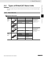
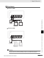
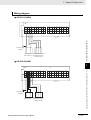
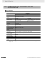
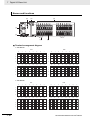
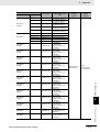
2-2-1
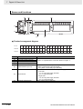
Slave Units List
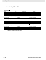
Digital I/O Slave Unit
Appearance
Models with
3-tier
terminal
block
GX-series EtherCAT Slave Unit User’s Manual
2
I/O points
Model
16 inputs (NPN)
GX-ID1611
16 inputs (PNP)
GX-ID1621
16 outputs (NPN)
GX-OD1611
16 outputs (PNP)
GX-OD1621
Relay 16 outputs
GX-OC1601
8 inputs and 8 outputs
(NPN)
GX-MD1611
8 inputs and 8 outputs
(PNP)
GX-MD1621
16 inputs (NPN)
16 inputs (PNP)
16 outputs (NPN)
16 outputs (PNP)
8 inputs and 8 outputs
(NPN)
8 inputs and 8 outputs
(PNP)
GX-ID1612
GX -ID1622
GX-OD1612
GX-OD1622
Features
• Equipped with a
removable screw
terminal block
• Possible to mount an
Expansion Unit
• Equipped with a
removable screw
terminal block
• Expansion Unit cannot
be mounted
GX-MD1612
GX-MD1622
2-3
2-2-1 Slave Units List
Type
Models with
2-tier
terminal
block
2-2 Types of EtherCAT Slave Units
2-2
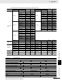
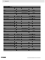
2 EtherCAT Slave Unit
Type
e-CON
Connectors
Appearance
I/O points
16 inputs (NPN)
Model
GX-ID1618
16 inputs (PNP)
GX-ID1628
16 outputs (NPN)
16 outputs (PNP)
8 inputs and 8 outputs
(NPN)
8 inputs and 8 outputs
(PNP)
32 inputs (NPN)
GX-OD1618
GX-OD1628
GX-MD1618
32 inputs (PNP)
GX-ID3228
32 outputs (NPN)
GX-OD3218
32 outputs (PNP)
GX-OD3228
16 inputs and 16 outputs
(NPN)
GX-MD3218
16 inputs and 16 outputs
(PNP)
GX-MD3228
Features
• Equipped with an
e-CON connector
• Expansion Unit cannot
be mounted
GX-MD1628
GX-ID3218
Analog I/O Slave Unit
Type
Models with
screw
terminal
blocks
Appearance
4 inputs
I/O points
Model
GX-AD0471
2 outputs
GX-DA0271
Features
• Equipped with a
removable screw
terminal block
• Possible to switch
input and output range
(voltage and current)
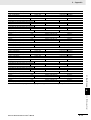
Encoder Input Slave Unit
Type
Models with
screw
terminal
blocks
2-4
Appearance
I/O points
2 inputs (5 V and 24 V
voltage input)
Model
GX-EC0211
2 inputs (Line driver input)
GX-EC0241
Features
• Equipped with a
removable screw
terminal block
• With 2 latch inputs/1
reset input
GX-series EtherCAT Slave Unit User’s Manual
2 EtherCAT Slave Unit
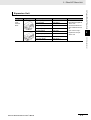
Type
Models with
2-tier
terminal
block
Appearance
Model
XWT-ID08
8 inputs (PNP)
XWT-ID08-1
8 outputs (NPN)
XWT-OD08
8 outputs (PNP)
XWT-OD08-1
16 inputs (NPN)
XWT-ID16
16 inputs (PNP)
XWT-ID16-1
16 outputs (NPN)
XWT-OD16
16 outputs (PNP)
XWT-OD16-1
Features
• Can be connected to
the following Digital I/O
Slave Unit
GX-ID1611/ID1621/O
D1611/OD1621/OC16
01
• Can connect only 1
Expansion Unit per
Slave Unit
2
2-2-1 Slave Units List
GX-series EtherCAT Slave Unit User’s Manual
I/O points
8 inputs (NPN)
2-2 Types of EtherCAT Slave Units
Expansion Unit
2-5
2 EtherCAT Slave Unit
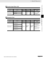
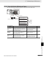
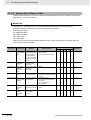
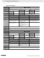
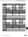
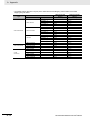
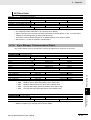
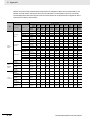
2-2-2
Installation, I/O Connection, and Power Supply Methods for Each
Slave Unit
Digital I/O Slave Unit
Type
Models with 2-tier
terminal block
Models with 3-tier
terminal block
Model
Slave Unit
installation
method
GX-ID1611
GX-ID1621
GX-OD1611
GX-OD1621
GX-OC1601
GX-MD1611
GX-MD1621
GX-ID1612
GX-ID1622
GX-OD1612
GX-OD1622
GX-MD1612
GX-MD1622
GX-ID1618
GX-ID1628
I/O
connection
method
Shared with
unit power
supply
GX-OD1618
GX-OD1628
GX-MD1618
GX-MD1628
e-CON
Connectors
GX-ID3218
GX-ID3228
External power
supply
I/O power supply
must be supplied
externally for
connected devices.
M3 screw
terminal
block
DIN track
e-CON connectors
Internal
power
supply
GX-OD3218
GX-OD3228
GX-MD3218
GX-MD3228
Shared with unit
power supply*
I/O power supply
must be supplied
externally for
connected devices.
Only inputs are
shared with unit
power supply.*
Shared with unit
power supply*
I/O power supply
must be supplied
externally for
connected devices.
Only inputs are
shared with unit
power supply.*
* Power for external I/O (sensors and actuators) is also supplied from the unit power supply.
For this reason, make sure to add current consumption of external I/O when examining output current of the unit
power supply.
Analog I/O Slave Unit
Type
Models with screw
terminal blocks
2-6
Model
Slave Unit
installation
method
I/O
connection
method
DIN track
M3 screw
terminal
block
GX-AD0471
GX-DA0271
Internal
power
supply
Shared with
unit power
supply
External power
supply
Not necessary
GX-series EtherCAT Slave Unit User’s Manual
2 EtherCAT Slave Unit
Type
Model
Slave Unit
installation
method
I/O
connection
method
DIN track
M3 screw
terminal
block
GX-EC0211
Models with screw
terminal blocks
GX-EC0241
Internal
power
supply
External power
supply
Shared with
unit power
supply
I/O power supply
must be supplied
externally for
connected devices.
2-2 Types of EtherCAT Slave Units
Encoder Input Slave Unit
2
Expansion Unit
Model
Slave Unit
installation
method
I/O
connection
method
Internal
power
supply
External power
supply
Shared with
unit power
supply
Varies depending
on the type of
mounted Digital I/O
Slave Unit
(Refer to "10-1-2
I/O Power Supply"
in Page 10 - 3.)
XWT-ID08 (−1)
Models with 2-tier
terminal block
XWT-OD08 (−1)
DIN track
XWT-ID16 (−1)
XWT-OD16 (−1)
GX-series EtherCAT Slave Unit User’s Manual
M3 screw
terminal
block
2-7
2-2-2 Installation, I/O Connection, and Power Supply
Methods for Each Slave Unit
Type
2 EtherCAT Slave Unit
2-8
GX-series EtherCAT Slave Unit User’s Manual
Basic Usage Procedures
3
This chapter explains the procedure of using EtherCAT Slave Units based on specific
setting examples.
3-1 Setup Examples and Basic Procedure . . . . . . . . . . . . . . . . . . . . . . . . . . . . . 3-2
3-1-1
3-1-2
System Setting Examples . . . . . . . . . . . . . . . . . . . . . . . . . . . . . . . . . . . . . . . . . 3-2
Basic Procedure . . . . . . . . . . . . . . . . . . . . . . . . . . . . . . . . . . . . . . . . . . . . . . . . 3-3
3-2 Setting and Wiring Hardware . . . . . . . . . . . . . . . . . . . . . . . . . . . . . . . . . . . . 3-4
3-2-1
3-2-2
3-2-3
3-2-4
3-2-5
Mounting and Setting EtherCAT Master Unit . . . . . . . . . . . . . . . . . . . . . . . . . .
Mounting and Setting Slave Units . . . . . . . . . . . . . . . . . . . . . . . . . . . . . . . . . . .
Wiring Communications Cables . . . . . . . . . . . . . . . . . . . . . . . . . . . . . . . . . . . .
Connecting Power Supplies . . . . . . . . . . . . . . . . . . . . . . . . . . . . . . . . . . . . . . .
Wiring I/O Devices . . . . . . . . . . . . . . . . . . . . . . . . . . . . . . . . . . . . . . . . . . . . . .
3-4
3-4
3-4
3-4
3-4
3-3 Starting Communications . . . . . . . . . . . . . . . . . . . . . . . . . . . . . . . . . . . . . . . 3-5
3-3-1
3-3-2
3-3-3
Starting a System . . . . . . . . . . . . . . . . . . . . . . . . . . . . . . . . . . . . . . . . . . . . . . . 3-5
Setting EtherCAT Communications . . . . . . . . . . . . . . . . . . . . . . . . . . . . . . . . . 3-5
Starting EtherCAT Communications . . . . . . . . . . . . . . . . . . . . . . . . . . . . . . . . . 3-5
3-4 Checking Operations . . . . . . . . . . . . . . . . . . . . . . . . . . . . . . . . . . . . . . . . . . . 3-6
3-4-1
3-4-2
3-4-3
Checking Unit Displays . . . . . . . . . . . . . . . . . . . . . . . . . . . . . . . . . . . . . . . . . . . 3-6
Confirming Data Read and Write . . . . . . . . . . . . . . . . . . . . . . . . . . . . . . . . . . . 3-6
Setting Slave Unit Parameter . . . . . . . . . . . . . . . . . . . . . . . . . . . . . . . . . . . . . . 3-6
GX-series EtherCAT Slave Unit User’s Manual
3-1
3 Basic Usage Procedures
3-1
Setup Examples and Basic
Procedure
This section explains the setup method by using simple system setting examples.
3-1-1
System Setting Examples
Connect each of the following Slave Units to the EtherCAT Master Unit and make the settings.
EtherCAT Master Unit
Digital I/O Slave Unit
GX-ID1611 (16 inputs)
+
Expansion Unit
XWT-ID16 (16 inputs)
Set the node address to 1.
Digital I/O Slave Unit
GX-OD1611 (16 outputs)
+
Expansion Unit
XWT-OD16 (16 outputs)
Set the node address to 2.
Analog I/O Slave Unit
GX-AD0471 (4 inputs)
Set the node address to 5.
Although it is not shown in the figure above, supply the unit power and the I/O power separately.
Reference
The setting example explained here is the basic setting of GX-series EtherCAT Slave Units.
If more detailed settings are required in actual operation, refer to the manual of the EtherCAT
Master Unit or pages on this manual explaining the detail for each Slave Unit (Chapter 7 to
Chapter 10).
Moreover, if your system configuration includes Slave Units other than our products, make the
setting upon referring to the manual of the relevant Slave Units.
3-2
GX-series EtherCAT Slave Unit User’s Manual
3 Basic Usage Procedures
Basic Procedure
Mounting and Setting EtherCAT Master Unit
Section 3-2-1
Mounting and Setting Slave Units
Section 3-2-2
3-1 Setup Examples and Basic Procedure
3-1-2
Wiring Communications Cables
Section 3-2-3
3
Connecting Power Supplies
Section 3-2-4
Wiring I/O Devices
Section 3-2-5
Starting a System
Section 3-3-1
Setting an EtherCAT Communications
Section 3-3-2
Starting EtherCAT Communications
Section 3-3-3
Checking Unit Displays
Section 3-4-1
Confirming Data Read and Write
Section 3-4-2
Setting Slave Unit Parameter
Section 3-4-3
This is the flow of the procedures explained in the following sections.
Starting Communications
Checking Operations
3-1-2 Basic Procedure
Setting and Wiring Hardware
Start
End
GX-series EtherCAT Slave Unit User’s Manual
3-3
3 Basic Usage Procedures
3-2
Setting and Wiring Hardware
Make settings and wiring of the EtherCAT Master Unit and Slave Units, and power supply.
3-2-1
Mounting and Setting EtherCAT Master Unit
Mount the EtherCAT Master Unit at the prescribed location and make settings of Unit No. and so on.
For the detailed explanation, refer to the manual of the EtherCAT Master Unit to be used.
3-2-2
Mounting and Setting Slave Units
Mount each Slave Unit at the prescribed location and make settings of node address and so on.
For details, refer to each item below.
z Mounting
"4-1 Mounting Slave Units" in page 4 - 2
z Setting
Pages in Chapter 6 to Chapter 10 which explain the general specification and details of each type of
Slave Units.
3-2-3
Wiring Communications Cables
Wire communications cables to the EtherCAT Master Unit and each Slave Unit.
For wiring method, refer to "4-2 Connecting to EtherCAT Network" in page 4 - 4.
3-2-4
Connecting Power Supplies
Connect the unit power supply to the EtherCAT Master Unit and Slave Units.
In addition, connect the I/O power supply to each Slave Unit as required.
For the connection method, refer to "4-3 Connecting to Unit Power Supply and I/O Power Supply" in
page 4 - 8 or the wiring diagram of each Slave Unit (in pages explaining the details).
3-2-5
Wiring I/O Devices
Connect input and output devices to each Slave Unit as required.
For the connection method, refer to "4-4 Connecting an External Device" in page 4 - 12 or the wiring
diagram of each Slave Unit (in pages explaining the details).
3-4
GX-series EtherCAT Slave Unit User’s Manual
3 Basic Usage Procedures
3-3
Starting Communications
3-3-1
Starting a System
Turn ON the power supply to each Unit.
(1) Unit power supply of EtherCAT Master Units
(2) Unit power supply of Slave Units (When the power is supplied, Slave Unit's [PWR] indicator is lit.)
(3) I/O power supply of Slave Units
3-3 Starting Communications
Start the system, allocate I/O data of Slave Units, and then start the EtherCAT communications.
For operational state and details of it, refer to "5-3 Communications State Transitions" in page 5 - 4.
3
Note that there are no restrictions on the order of turning ON the power supplies.
Setting EtherCAT Communications
The following communications are performed in EtherCAT.
z PDO communications (remote I/O communications)
Allocate I/O data of Slave Units to the EtherCAT Master Unit (PDO mapping) and perform PDO
communication (remote I/O communications).
For the detailed explanation of I/O data of each Slave Unit, refer to "I/O Data Allocation (PDO
Mapping)” in Chapter 7 to Chapter 9.
Note that the ESI file are used to allocate I/O data.
For the detailed explanation of the procedure, refer to the manual of the EtherCAT Master Unit to be
used and the manual of the Configuration Tool.
z SDO communications (message communications)
For the method of using, refer to the manual of the EtherCAT Master Unit to be used.
Refer to "Appendix A - 1 Object Dictionary" for the detailed explanation of objects implemented on
GX-series EtherCAT Slave Units.
Note that the SDO communications can be used in the pre-operational state or more.
3-3-3
Starting EtherCAT Communications
Shift to the operational state (EtherCAT communications possible) to start the EtherCAT
communications.
For how to shift to the operational state, refer to the manual of the EtherCAT Master Unit to be used.
GX-series EtherCAT Slave Unit User’s Manual
3-5
3-3-1 Starting a System
3-3-2
3 Basic Usage Procedures
3-4
Checking Operations
Confirm that the LED indicators of the EtherCAT Master Unit and Slave Units are normal status and that
I/O data is correctly read and written.
Moreover, make parameter settings for Slave Units as required.
3-4-1
Checking Unit Displays
z EtherCAT Master Unit
Refer to the manual of the EtherCAT Master Unit to be used.
z EtherCAT Slave Units
Check that the status indicator of each Slave Unit is as follows.
LED
PWR
L/A IN
L/A OUT
RUN
ERR
3-4-2
State
ON
Flickering
Flickering (turned OFF for the terminal Slave Unit only)
ON
OFF
Confirming Data Read and Write
Use the Configuration Tool to read IN data and OUT data of the EtherCAT Master Unit in order to
check that the I/O data is correctly read and written.
3-4-3
Setting Slave Unit Parameter
Make parameter settings for each Slave Unit as required via the SDO communications.
For the details of parameters that can be set, refer to the pages explaining details of each Slave Unit in
Chapter 7 to Chapter 9.
3-6
GX-series EtherCAT Slave Unit User’s Manual
Installation and Wiring
This chapter explains the mounting and wiring methods of the EtherCAT Slave Unit.
4
4-1 Mounting Slave Units . . . . . . . . . . . . . . . . . . . . . . . . . . . . . . . . . . . . . . . . . . . 4-2
4-1-1
4-1-2
4-1-3
4-1-4
Mounting Preparation . . . . . . . . . . . . . . . . . . . . . . . . . . . . . . . . . . . . . . . . . . . .
Mounting Direction . . . . . . . . . . . . . . . . . . . . . . . . . . . . . . . . . . . . . . . . . . . . . .
Mounting Method . . . . . . . . . . . . . . . . . . . . . . . . . . . . . . . . . . . . . . . . . . . . . . .
Removal Method . . . . . . . . . . . . . . . . . . . . . . . . . . . . . . . . . . . . . . . . . . . . . . . .
4-2
4-2
4-2
4-3
4-2 Connecting to EtherCAT Network . . . . . . . . . . . . . . . . . . . . . . . . . . . . . . . . 4-4
4-2-1
4-2-2
4-2-3
4-2-4
Precautions for Network Connection . . . . . . . . . . . . . . . . . . . . . . . . . . . . . . . .
Preparation for Connecting Network . . . . . . . . . . . . . . . . . . . . . . . . . . . . . . . . .
Connecting Communications Cables and Connectors . . . . . . . . . . . . . . . . . . .
Connecting to Communications Cables . . . . . . . . . . . . . . . . . . . . . . . . . . . . . .
4-4
4-5
4-6
4-7
4-3 Connecting to Unit Power Supply and I/O Power Supply . . . . . . . . . . . . . 4-8
4-3-1
4-3-2
4-3-3
4-3-4
Precautions at Supplying Unit Power and I/O Power . . . . . . . . . . . . . . . . . . . . 4-8
Unit Power Supply Specifications . . . . . . . . . . . . . . . . . . . . . . . . . . . . . . . . . . . 4-9
Connecting the Unit Power Supply . . . . . . . . . . . . . . . . . . . . . . . . . . . . . . . . . . 4-9
Connecting the I/O Power Supply . . . . . . . . . . . . . . . . . . . . . . . . . . . . . . . . . . 4-10
4-4 Connecting an External Device . . . . . . . . . . . . . . . . . . . . . . . . . . . . . . . . . 4-12
4-4-1
4-4-2
Connecting to a Screw Terminal Block . . . . . . . . . . . . . . . . . . . . . . . . . . . . . . 4-12
Connecting to e-CON Connector Terminals . . . . . . . . . . . . . . . . . . . . . . . . . . 4-13
GX-series EtherCAT Slave Unit User’s Manual
4-1
4 Installation and Wiring
4-1
Mounting Slave Units
This section explains the mounting methods of Slave Units to the DIN track.
4-1-1
Mounting Preparation
Prepare the following devices.
Product name
35-mm DIN track
End plate
4-1-2
Model
PFP-50N
PFP-100N
PFP-100N2
PFP-M
Comment
Length 50 cm
Length 100 cm
Length 100 cm
2 end plates are required for each Slave Unit.
Mounting Direction
There are no restrictions in the orientation unless otherwise specified in the instruction pages for the
Slave Unit.
Mounting is possible in any of the following 6 orientations.
Vertical direction
4-1-3
Mounting Method
1
Hook the top side of groove on backside of the Slave Unit to the top side of the DIN
track, lower the DIN track mounting hook, engage the Slave Unit to the track, and press
up the mounting hook to fix it.
(2)
DIN track
(1)
DIN track mounting hook
4-2
GX-series EtherCAT Slave Unit User’s Manual
4 Installation and Wiring
2
Hook the bottom side of the end plate to the bottom side of the DIN track and then hook
the top side.
Attach an end plate on each side of the Unit.
(2)
4-1 Mounting Slave Units
(1)
4
End plate
4-1-4 Removal Method
Precautions for Safe Use
After the operation, make sure to check that the Slave Unit is securely mounted.
4-1-4
Removal Method
Loosen the screws on the end plate and remove the end plate from the DIN track. Then pull down the
DIN track mounting hook to release the lock. Pull out the Slave Unit straight toward you.
GX-series EtherCAT Slave Unit User’s Manual
4-3
4 Installation and Wiring
4-2
Connecting to EtherCAT Network
This section explains how to lay down EtherCAT network.
4-2-1
Precautions for Network Connection
Observe the precautions below when laying down the EtherCAT network.
Precautions at laying down network
• When laying down an EtherCAT network, take sufficient safety measures and construct the network
according to the standards. We recommend to request specialized constructors familiar with the
safety measures and standards to perform the laying operation.
• Do not lay down EtherCAT network devices near any devices generating noise.
If there is no choice but to lay them down in a noisy environment, make sure to take noise measures
such as housing each device in metal cases.
Precautions at laying down communications cables
• Check the following items for communications cables to be used.
• Are there any disconnected cables?
• Are any cables short-circuited?
• Are there any problems in connector connections?
• To connect a cable to communications connector of each device, insert it securely until the connector
of the communications cable is locked.
• Lay down and wire the communications cables separately from high-voltage electrical power lines.
• Do not lay down the cables near devices generating noise.
• Do not lay down the cables in high-temperature and high-humidity environment.
• Use the cables in locations without powder dust and oil mist.
• There is a limit to the bending radius of communications cables. Check the specification of
communications cables to be used for the information on bending radius.
4-4
GX-series EtherCAT Slave Unit User’s Manual
4 Installation and Wiring
4-2-2
Preparation for Connecting Network
Prepare the following devices.
Product name
RJ45 connector
100BASE-TX (Category 5 or higher)
Double-shield (aluminum tape + braided shielding)
Category 5 or higher
Shielded
Precautions for Correct Use
Reference
We recommend cables with double, aluminum tape and braded shielding, taking noise
resistance into consideration.
GX-series EtherCAT Slave Unit User’s Manual
4-5
4
4-2-2 Preparation for Connecting Network
• The maximum cable length between connected nodes is 100 m. Note that some cables do not
guarantee 100 m. In general, if the conductors are strand wire, the transmission performance
will be lower than solid wire and the operation at 100-m distance cannot be guaranteed.
Confirm details with the cable manufacturer.
• When selecting connectors, check that the cables to be used conform to connectors. Items to
be checked include conductor size, conductor wire type (solid wire/twisted wire, 2/4 pairs), and
outer diameter.
4-2 Connecting to EtherCAT Network
Twisted-pair cable
(Cables with connectors
below are also allowed.)
Comment
4 Installation and Wiring
4-2-3
Connecting Communications Cables and Connectors
Connect a communications cable and a connector by wiring them straight as shown below.
Wire color
Wire color
Pin No.
Pin No.
1
White-Green
White-Green
1
2
Green
Green
2
3
White-Orange
White-Orange
3
4
Blue
Blue
4
5
White-Blue
White-Blue
5
6
Orange
Orange
6
7
White-Brown
White-Brown
7
8
Brown
Brown
Connector
hood
Shielded cable *
Shielded cable*
8
Connector
hood
* Connect both ends of cable shielded wires to the connector hoods.
Reference
There are 2 types of wiring standards for Ethernet cables : "T568A" and "T568B."
The figure above shows a wiring method conforming to the standard "T568A". The wiring
method conforming to the standard "T568B" can also be used.
4-6
GX-series EtherCAT Slave Unit User’s Manual
4 Installation and Wiring
4-2-4
Connecting to Communications Cables
EtherCAT networks allow free wiring in any connection forms. Connection before and after the
GX-series EtherCAT Slave Units shall be made in daisy chain connection.
EtherCAT Master Unit
4-2 Connecting to EtherCAT Network
Connect the communications cable from the EtherCAT Master Unit to the [CN IN] connector of the
Slave Units. Connect another the communications cable from the [CN OUT] connector of the first Slave
Unit to the [CN IN] connector of the next Slave Unit.
Note that nothing should be connected to the [CN OUT] connector of the Slave Unit at the terminal end
of the network.
4
Communications cable
4-2-4 Connecting to Communications Cables
[CN IN] connector
L1
[CN OUT] connector
L2
Slave Unit
Ln
Do not connect anything.
Terminal Slave Unit
Precautions for Correct Use
• The cable length between each Slave Unit (L1, L2, ... Ln) must be within 100 m.
• Connect cables securely until communications cable connectors click and are fixed in place.
• When you wire the communications cables, observe their specifications (bending radius and
so on) defined by the cable manufacturer.
GX-series EtherCAT Slave Unit User’s Manual
4-7
4 Installation and Wiring
4-3
Connecting to Unit Power Supply
and I/O Power Supply
The following power supplies are required to operate the EtherCAT network.
• Unit power supply: For communication and internal operation of Slave Units.
• I/O power supply: For input/output operation of external I/O devices of each Slave Unit.
This section explains how to supply the unit power supply and I/O power supply.
4-3-1
Precautions at Supplying Unit Power and I/O Power
When supplying the unit power supply and I/O power supply, take the followings into consideration for
allowable current of cables and connectors, voltage drop, and layout of power supplies.
z Consideration to cable voltage drop
The power supply voltage of a Slave Unit farthest to the power supply must be within the allowable
variation range.
z Supplying unit power supply and I/O power supply from multiple sources
When the unit power and I/O power are supplied from multiple power supplies instead of from one power
supply, the line current, voltage drop, and cable size can be reduced. Moreover, it is effective to secure
safety of the system at power supply errors.
z If power supply errors occur
Consideration on layout and grouping of power supplies differ by whether you want to stop the entire
system or not when a power supply error occurs.
If you want to avoid stopping the entire system, we recommend to set power supplies at several
locations and supply power to groups of Slave Units, or take similar measures.
This has also the effects of reducing voltage drop and cable size and so on.
4-8
GX-series EtherCAT Slave Unit User’s Manual
4 Installation and Wiring
4-3 Connecting to Unit Power Supply and I/O Power Supply
4-3-2
Unit Power Supply Specifications
Use a general purpose power supply that satisfies the following specifications.
Item
Output voltage
Output ripple
Output current
Isolation
Specification
24 VDC ± 10%
600 mVp-p
Has the capacity to supply power more than the total current
consumption of each Slave Unit
Between output and AC power supply as well as between output and
chassis ground
We recommend S8JX series power supplies made by OMRON for the unit power supply for Slave
Units.
Precautions for Correct Use
4-3-3
Connecting the Unit Power Supply
Connect a cable from the 24-VDC unit power supply to the unit power supply connector on each Slave
Unit, and supply power to individual Slave Units.
To 24-VDC unit
power supply
Unit power
supply cable
Pin terminal
+V
terminal
−V
terminal
Mount a pin terminal, or equivalent to the unit power supply cable so that it will not be displaced.
GX-series EtherCAT Slave Unit User’s Manual
4-9
4
4-3-2 Unit Power Supply Specifications
• The I/O power supply for the input section of the e-CON connector type Slave Units is shared
with the unit power supply. To calculate the output current of the unit power supply, be sure to
use "unit power supply current consumption" to which "input current" and "input connection
device supply current" have been added.
• Use a power supply with sufficient capacity considering the inrush current at startup.
4 Installation and Wiring
z Recommended product
The following pin terminals are recommended for the unit power supply cables.
Model
Applicable wire
size
AI0,5-10WH
0.5 mm/AWG20
H0.5/16 orange
0.5 mm/AWG20
Crimping tool
Manufacturer
CRIMPFOX UD6
(Product No. 1204436)
or CRIMPFOX ZA3
series
Crimper PZ1.5
(Product No. 900599)
Phoenix Contact
Co., Ltd.
Weidmueller Japan Co., Ltd.
Also, the following screwdriver is recommended for removing pin terminals.
Model
XW4Z-00C
4-3-4
Manufacturer
OMRON
Connecting the I/O Power Supply
z Units with screw terminal blocks
It supplies the 24-VDC I/O power to the I/O power supply terminal on each Slave Unit.
For the locations of I/O power supply terminals, see the terminal layout diagrams for each Slave Unit
or wiring diagrams in Chapter 7 to Chapter 10.
Moreover, for how to connect power supplies to terminals, refer to "4-4-1 Connecting to a Screw
Terminal Block" in Page 4 - 12.
z Units with e-CON connectors
The following e-CON connector type Slave Units (Output Slave Units and output sections of
Input/Output Slave Units) are equipped with I/O power supply connectors to supply I/O power to
external devices.
• GX-OD1618/OD1628/MD1618 (output section only)/MD1628 (output section only)
• GX-OD3218/OD3228/MD3218 (output section only)/MD3228 (output section only)
To connect external devices to these Slave Units, supply the 24-VDC I/O power to the I/O power
supply connector.
24-VDC
power supply
+
V terminal
−
G terminal
Mount a pin terminal, or equivalent to the power supply cable so that it will not be displaced.
4 - 10
GX-series EtherCAT Slave Unit User’s Manual
4 Installation and Wiring
4-3 Connecting to Unit Power Supply and I/O Power Supply
z Recommended product
The following pin terminals are recommended for the unit power supply cables.
Model
Applicable wire
size
AI0,5-10WH
0.5 mm/AWG20
H0.5/16 orange
0.5 mm/AWG20
Crimping tool
CRIMPFOX UD6
(Product No. 1204436)
or CRIMPFOX ZA3
series
Crimper PZ1.5
(Product No. 900599)
Manufacturer
Phoenix Contact
Co., Ltd.
Weidmueller Japan Co., Ltd.
Also, the following screwdriver is recommended for removing pin terminals.
Model
XW4Z-00C
Manufacturer
OMRON
4
4-3-4 Connecting the I/O Power Supply
GX-series EtherCAT Slave Unit User’s Manual
4 - 11
4 Installation and Wiring
4-4
Connecting an External Device
Connect an external device to the I/O terminal of a Slave Unit.
The method of connection differs between Units with screw terminal blocks and Units with e-CON
connectors.
4-4-1
Connecting to a Screw Terminal Block
After mounting a crimp terminal to the cable of the external device to be connected, connect it to the
terminal block.
1
Mount the following crimp terminal to the signal line of the cable.
φ3.2 mm min.
3.2 mm min.
6.0 mm max.
2
6.0 mm max.
Connect the signal line to the terminal block.
Tighten the terminal block screws to the appropriate tightening torque of 0.5 N • m.
The terminal block is removable; remove the left and right screws if it is necessary to remove
the terminal block to connect the signal line.
Precautions for Correct Use
To remove the terminal block from the Slave Unit, loosen the left and right mounting screws
alternately. When mounting the terminal block as well, tighten the left and right screws
alternately.
If you tighten or loosen only one of the screws all the way without tightening or loosening the
other screw using an electric screwdriver, the terminal block will be distorted and cracked.
4 - 12
GX-series EtherCAT Slave Unit User’s Manual
4 Installation and Wiring
4-4-2
Connecting to e-CON Connector Terminals
Connect the dedicated e-CON connector to the cables of the external device to be connected and then
connect it to the connector terminal.
The wire size and sheath diameter of applicable cables vary by the type of e-CON connector.
Use the next table to check that the e-CON connectors to be used conform to the wire size and sheath
diameter of the cables of the connected device.
z Tyco Electronics connectors
Model
3-1473562-4
1-1473562-4
1473562-4
2-1473562-4
4-1473562-4
Housing color
Orange
Red
Yellow
Blue
Green
Applicable wire range
Sheath diameter: 0.6 to 0.9 mm
Sheath diameter: 0.9 to 1.0 mm
Cross-sectional area: 0.08 to
Sheath diameter: 1.0 to 1.15 mm
0.5 mm2
Sheath diameter: 1.15 to 1.35 mm
Sheath diameter: 1.35 to 1.60 mm
Model
Housing color
Applicable wire range
37104-3101-000FL Red
AWG26 (0.14mm to AWG24 (0.2mm2)
Sheath diameter: 0.8 to 1.0 mm
37104-3122-000FL Yellow
AWG26 (0.14mm2) to AWG24 (0.2mm2)
Sheath diameter: 1.0 to 1.2 mm
37104-3163-000FL Orange
AWG26 (0.14mm2) to AWG24 (0.2mm2)
Sheath diameter: 1.2 to 1.6 mm
37104-2124-000FL Green
AWG22 (0.3mm2) to AWG20 (0.5mm2)
Sheath diameter: 1.0 to 1.2 mm
37104-2165-000FL Blue
AWG22 (0.3mm2) to AWG20 (0.5mm2)
Sheath diameter: 1.2 to 1.6 mm
37104-2206-000FL Gray
AWG22 (0.3mm2) to AWG20 (0.5mm2)
Sheath diameter: 1.6 to 2.0 mm
2)
z Panasonic Electric Works connectors
Model
Housing color
Applicable wire range
AXF12142
Red
AWG22 (0.3mm ) to AWG20 (0.5mm2)
Sheath diameter: 1.2 to 2.0 mm
AXF12146
Yellow
AWG28 (0.08mm2) to AWG24 (0.2mm2)
Sheath diameter: 0.7 to 1.2 mm
2
z OMRON connectors
Model
XN2A-1470
Specification
Spring
clamp type
GX-series EtherCAT Slave Unit User’s Manual
4
4-4-2 Connecting to e-CON Connector Terminals
z Sumitomo 3M connectors
4-4 Connecting an External Device
Checking the e-CON connector and cable wire size
Applicable wire range
(0.08mm2
AWG28
) to AWG20 (0.5mm2)
Sheath diameter: 1.5 mm max.
4 - 13
4 Installation and Wiring
Processing external devices cables
z Using Tyco Electronics, Sumitomo 3M or Panasonic Electric Works
connectors
Cables of connected devices are normally cut in semi-strip or strip specification as shown in the next
figures.
Semi-strip specification
Strip specification
When the cables are prepared this way, an e-CON connector cannot be attached. First cut the end
and remove the cable sheath as shown in the following diagram. (Do not strip the sheaths of the
core wires.)
20 mm min.
Core wires
Strip sheaths of core wires
z Using OMRON connectors
Align the cable with the STRIP GAUGE described on the side of the connector. Remove 7 to 8 mm
of the wiring sheath, and twist the exposed wires several times.
7 to 8 mm
4 - 14
GX-series EtherCAT Slave Unit User’s Manual
4 Installation and Wiring
Inserting wires into the cable connector
Insert the cable wire of the extend device to the cable connector.
Make sure that the terminal numbers printed on the connector cover matches the colors of wires as
shown in the next table.
1
2
3
4
Notes
NPN Slave Unit
3-wire sensor
2-wire sensor
Brown (red)
−
−
−
Blue (black)
Blue (black)
Black (white)
Brown (white)
PNP Slave Unit
3-wire sensor
2-wire sensor
Brown (red)
Brown (white)
−
−
Blue (black)
−
Black (white)
Blue (black)
Wire colors have been changed according to revisions in the JIS standards for photoelectric sensors and
proximity sensors.
The colors in parentheses are the wire colors prior to the revisions.
z Using Tyco Electronics, Sumitomo 3M or Panasonic Electric Works
connectors
2
4
Insert the wire all the way to the wire insertion opening on the cover of the cable
connector.
Use a pliers, or equivalent to press the cover into the body. At this point, press the cover
straight in such that the cover is horizontal to the body.
z Using OMRON connectors
1
Use a flat-blade screwdriver to push the operation lever inside the connector's operation
opening until it locks, as shown in the following diagram.
Flat-blade
Screwdriver
Operation opening
GX-series EtherCAT Slave Unit User’s Manual
4 - 15
4-4-2 Connecting to e-CON Connector Terminals
1
4-4 Connecting an External Device
Terminal
number
4 Installation and Wiring
2
Insert the wire all the way to the back of the wire insertion opening.
Check that the sheath of the wire is inserted into the wire insertion opening, and that the end of
the conductor has passed through the connection part.
Connection part
3
Wire insertion opening
Insert a screwdriver into the reset opening and pull back the operation lever lightly.
A click will be heard and the operation lever will return to its normal position.
Operation lever (white)
4
Wire sheath part
Reset opening
Lightly pull the wire to confirm that it is connected properly.
Precautions for Correct Use
To remove a wire, push in the operation lever, check that the operation lever has locked, and
then pull out the wire. Also, after removing the wire, always return the operation lever to its
normal position.
4 - 16
GX-series EtherCAT Slave Unit User’s Manual
EtherCAT Communications
This chapter explains the overview of EtherCAT communications.
5-1 Structure of CAN application protocol over EtherCAT (CoE) . . . . . . . . . . 5-2
5-2 EtherCAT Slave Information File (ESI File) . . . . . . . . . . . . . . . . . . . . . . . . . 5-3
5-3 Communications State Transitions . . . . . . . . . . . . . . . . . . . . . . . . . . . . . . . 5-4
5-4 Process Data Objects (PDO) . . . . . . . . . . . . . . . . . . . . . . . . . . . . . . . . . . . . . 5-5
5-4-1
5-4-2
5-4-3
5-4-4
Overview . . . . . . . . . . . . . . . . . . . . . . . . . . . . . . . . . . . . . . . . . . . . . . . . . . . . . .
PDO Mapping Settings . . . . . . . . . . . . . . . . . . . . . . . . . . . . . . . . . . . . . . . . . . .
Sync Manager PDO Assignment Settings . . . . . . . . . . . . . . . . . . . . . . . . . . . .
Fixed PDO Mapping . . . . . . . . . . . . . . . . . . . . . . . . . . . . . . . . . . . . . . . . . . . . .
5-5
5-5
5-6
5-7
5-5 Service Data Object (SDO) . . . . . . . . . . . . . . . . . . . . . . . . . . . . . . . . . . . . . . 5-9
5-5-1
5-5-2
Overview . . . . . . . . . . . . . . . . . . . . . . . . . . . . . . . . . . . . . . . . . . . . . . . . . . . . . . 5-9
Abort Codes . . . . . . . . . . . . . . . . . . . . . . . . . . . . . . . . . . . . . . . . . . . . . . . . . . . 5-9
5-6 EtherCAT Master Unit - Slave Unit Communications . . . . . . . . . . . . . . . . 5-10
5-6-1
FREE RUN Mode . . . . . . . . . . . . . . . . . . . . . . . . . . . . . . . . . . . . . . . . . . . . . . 5-10
5-7 Emergency Messages . . . . . . . . . . . . . . . . . . . . . . . . . . . . . . . . . . . . . . . . . 5-12
5-7-1
5-7-2
Emergency Message Notification . . . . . . . . . . . . . . . . . . . . . . . . . . . . . . . . . . 5-12
Diagnosis History . . . . . . . . . . . . . . . . . . . . . . . . . . . . . . . . . . . . . . . . . . . . . . 5-12
5-8 Sysmac Device Functions . . . . . . . . . . . . . . . . . . . . . . . . . . . . . . . . . . . . . . 5-13
GX-series EtherCAT Slave Unit User’s Manual
5-1
5
5 EtherCAT Communications
5-1
Structure of CAN application
protocol over EtherCAT (CoE)
Normally, multiple protocols can be transferred by EtherCAT. But GX-series EtherCAT Slave Units use
"CAN application protocol over EtherCAT (CoE)", a communication interface to be applied for EtherCAT
devices, as the device profile of the open network standard "CAN application protocol."
The figure below shows the structure of CoE in GX-series EtherCAT Slave Units.
GX-series EtherCAT Slave Units
Application layer
Slave application
Object dictionary
Communications
status transitions
SDO (mailbox)
Registers
Mailbox
PDO mapping
PDO (cyclic)
SyncManager
Process data
FMMU
EtherCAT data link layer
EtherCAT physical layer
CAN application protocol has two types of object dictionaries, PDO (Process Data Object) and SDO
(Service Data Object) .
PDO is composed of object dictionaries that can be mapped. The process data is defined by PDO
mapping.
PDO is primarily used in PDO communications for regularly exchanging process data.
Moreover, SDO is able to read and write all object dictionaries and is used in non-fixed-cycle type SDO
(event type messages) communications.
By using the CoE interface to set object SDO and PDO dictionaries, EtherCAT can provide EtherCAT
devices with the same device profile as CAN application protocol.
5-2
GX-series EtherCAT Slave Unit User’s Manual
5 EtherCAT Communications
5-2
EtherCAT Slave Information File
(ESI File)
Configuration tool
EtherCAT Master Unit
Network
configuration
information
ESI
files
5-2 EtherCAT Slave Information File (ESI File)
An EtherCAT Slave Information (ESI) file contains the setting information of an EtherCAT Slave Unit.
Various EtherCAT communications setting can be defined from the ESI files of connected Slave Units
and the network connection information.
ESI files are installed in the configuration tool to create network configuration information.
You can download the network configuration information to the EtherCAT Master Unit to configure the
EtherCAT network.
EtherCAT Slave Units
5
Communications are started according to the
communications settings and the network
configuration in the ESI files that are installed.
GX-series EtherCAT Slave Unit User’s Manual
5-3
5 EtherCAT Communications
5-3
Communications State Transitions
The EtherCAT State Machine (ESM) indicates the state transition model of EtherCAT Slave Unit
communications control. It is controlled by EtherCAT Master Unit.
The following figure shows the communications state transitions from power ON.
Power ON
Initialization
Pre-Operational
Safe-Operational
Operational
SDO
communi
cations
Not
possible.
PDO
PDO
transmiss
reception
ion
Not
Not
possible.
possible.
Pre-Operational
(Pre-Op)
Possible
Not
possible.
Not
possible.
Safe-Operational
(Safe-Op)
Possible
Possible
Not
possible.
Operational (Op)
Possible
Possible
Possible
State
Initialization (Init)
5-4
Contents
Communications are being initialized.
Communications are not possible.
SDO (message) communications are
possible in this state.
This state is entered after initialization has
been completed. It is used to initialize
network settings.
In this state, PDO transmissions are possible
in addition to SDO (message)
communications.
PDO sendings can be used to send
information such as status from the Slave
Unit.
Normal communication state
PDO communications can be used to control
the I/O data.
GX-series EtherCAT Slave Unit User’s Manual
5 EtherCAT Communications
5-4
5-4-1
Process Data Objects (PDO)
Overview
The process data objects (PDO) are used for real-time data transfer via cyclic communications.
There are two types in PDO: RxPDO that receives data from the EtherCAT Master Unit and TxPDO that
sends the present value from a EtherCAT Slave Unit to the EtherCAT Master Unit.
TxPDO
input data, status, and so on
EtherCAT
Slave
Unit
It is possible to hold multiple objects in the EtherCAT application layer so that various process data of
EtherCAT Slave Units can be transferred. The details of process data are described in PDO Mapping
Objects and Sync Manager PDO Assignment Objects.
GX-series EtherCAT Slave Units support PDO mapping for I/O control.
PDO Mapping Settings
The PDO mapping indicates the mapping for application objects (realtime process data) between the
object dictionary and PDO.
The number of mapped objects is described in sub-index 0 of the mapping table. In this mapping table,
indexes 1600 hex to 17FF hex are used for RxPDO and 1A00 hex to 1BFF hex are used for TxPDO.
GX-series EtherCAT Slave Unit User’s Manual
5-5
5
5-4-1 Overview
5-4-2
5-4 Process Data Objects (PDO)
EtherCAT
Master
Unit
RxPDO
output data, operation command, and so on
5 EtherCAT Communications
The figure below shows an example of PDO mapping.
Mapping objects
Object dictionary
Index
Sub
1ZZZ hex 01 hex
Object contents
6TTT hex TT hex
8
1ZZZ hex 02 hex 6UUU hex UU hex
8
1ZZZ hex 03 hex
16
6YYY hex YY hex
PDO-Length : 32 Bit
PDO_1
Application objects
6TTT hex TT hex
5-4-3
Object A
Object B
Object D
Object A
6UUU hex UU hex
Object B
6VVV hex VV hex
Object C
6YYY hex YY hex
Object D
6ZZZ hex ZZ hex
Object E
Sync Manager PDO Assignment Settings
A sync manager channel consists of several PDOs. The sync manager PDO assignment objects
describe how these PDOs are related to the Sync Manager.
The number of PDOs is given in sub-index 0 of the sync manager PDO assignment table.
In this table, index 1C12 hex is for RxPDOs and 1C13 hex is for TxPDOs.
Sync manager PDO
assignment objects
The figure below shows an example of sync manager PDO mapping.
Index
Sub
Object contents
1C1Z hex
1
1A00 hex
1C1Z hex
2
1A01 hex
1C1Z hex
3
1A03 hex
Sync manager entity Z
PDO A
Mapping objects
1A00 hex
5-6
PDO B
PDO D
PDO A
1A01 hex
PDO B
1A02 hex
PDO C
1A03 hex
PDO D
1A04 hex
PDO E
1A05 hex
PDO F
1A06 hex
PDO G
GX-series EtherCAT Slave Unit User’s Manual
5 EtherCAT Communications
5-4-4
Fixed PDO Mapping
The tables below show the details of fixed PDO mapping for GX-series EtherCAT Slave Units.
Note that it is not possible to change fixed PDO details.
z PDO mapping for Digital I/O Slave Unit
Fixed PDO mapping of a Digital I/O Slave Unit is determined by the number of inputs and/or outputs
per Unit and whether or not Expansion Units are connected.
257th transmit
PDO Mapping
(1B00 hex)
258th transmit
PDO Mapping
(1B01 hex)
GX-series EtherCAT Slave Unit User’s Manual
Write output 16-bit (6300 hex)
Write output 32-bit (6320 hex)
5
5-4-4 Fixed PDO Mapping
258th receive
PDO Mapping
(1701 hex)
5-4 Process Data Objects (PDO)
257th receive
PDO Mapping
(1700 hex)
8 outputs of Slave Unit
8 outputs of Expansion Unit only
16 outputs of Slave Unit only
16 outputs of Expansion Unit only
16 outputs of Slave Unit and 8
outputs of Expansion Unit (24
outputs in total)
32 outputs of Slave Unit only
16 outputs of Slave Unit and 16
outputs of Expansion Unit (32
outputs in total)
8 outputs of Slave Unit
8 outputs of Expansion Unit only
16 outputs of Slave Unit only
16 outputs of Expansion Unit only
16 outputs of Slave Unit and 8
outputs of Expansion Unit (24
inputs in total)
32 outputs of Slave Unit only
16 outputs of Slave Unit and 16
outputs of Expansion Unit (32
inputs in total)
8 inputs of Slave Unit
8 inputs of Expansion Unit only
16 inputs of Slave Unit only
16 inputs of Expansion Unit only
16 inputs of Slave Unit and 8
inputs of Expansion Unit (24
inputs in total)
32 inputs of Slave Unit only
16 inputs of Slave Unit and 16
inputs of Expansion Unit (32
inputs in total)
8 inputs of Slave Unit
8 inputs of Expansion Unit only
16 inputs of Slave Unit only
16 inputs of Expansion Unit only
16 inputs of Slave Unit and 8
inputs of Expansion Unit (24
inputs in total)
32 inputs of Slave Unit only
16 inputs of Slave Unit and 16
inputs of Expansion Unit (32
inputs in total)
Write output bits (3220 hex)
Write output 16-bit (6100 hex)
Write output 32-bit (6120 hex)
Read input bits (3020 hex)
5-7
5 EtherCAT Communications
512th transmit
PDO Mapping
(1BFF hex)
Sysmac errors
Sysmac Error (2002 hex)
Reference
You cannot assign 1700 hex and 1701 hex or 1B00 hex and 1B01 hex at the same time.
z Analog I/O Slave Unit PDO Mappings
257th receive
PDO Mapping
(1700 hex)
257th transmit
PDO Mapping
(1B00 hex)
512th transmit
PDO Mapping
(1BFF hex)
Write analog output 16-bit (6411 hex) *1
Read analog input 16-bit (6401 hex) *2
Sysmac Error (2002 hex)
*1 Analog Output Slave Unit only.
*2 Analog Input Slave Unit only.
z Encoder Input Slave Unit PDO Mappings
257th receive
PDO Mapping
(1700 hex)
258th receive
PDO Mapping
(1701 hex)
259th receive
PDO Mapping
(1702 hex)
257th transmit
PDO Mapping
(1B00 hex)
258th transmit
PDO Mapping
(1B01 hex)
259th transmit
PDO Mapping
(1B02 hex)
260th transmit
PDO Mapping
(1B03 hex)
261th transmit
PDO Mapping
(1B04 hex)
512th transmit
PDO Mapping
(1BFF hex)
Instruction Bits (4020 hex)
Preset Value (4011 hex)
Instruction Flag (4021 hex)
Position Value (4010 hex)
Latch Value A (4012 hex)
Latch Value B (4013 hex)
Status Bits (4030 hex)
Status Flag (4031 hex)
Sysmac Error (2002 hex)
Reference
You cannot assign 1700 hex and 1702 hex or 1B03 hex and 1B04 hex at the same time.
5-8
GX-series EtherCAT Slave Unit User’s Manual
5 EtherCAT Communications
5-5
5-5-1
Service Data Object (SDO)
Overview
GX-series EtherCAT Slave Units support the SDO communications.
The EtherCAT Master Unit is able to make parameter settings and monitor status by reading and writing
data from and to entries in object dictionaries via the SDO communications.
5-5 Service Data Object (SDO)
5-5-2
Abort Codes
The table below shows abort codes of SDO communications errors.
Meaning
Toggle bit not changed
SDO protocol timeout
Client/Server command specifier not valid or unknown
Out of memory
Unsupported access to an object
Attempt to read a write only object
Attempt to write to a read only object
The object does not exist in the object directory.
The object cannot be mapped into the PDO.
The number and length of the objects to be mapped would exceed the PDO length.
General parameter incompatibility reason
General internal incompatibility in the device.
Access failed due to a hardware error.
Data type does not match, length of service parameter does not match.
Data type does not match, length of service parameter too high.
Data type does not match, length of service parameter too low.
Sub-index does not exist.
Value range of parameter exceeded (only for write access)
Value of parameter written too high
Value of parameter written too low
Maximum value is less than minimum value.
General error
Data cannot be transferred or stored to the application.
08000021 hex
Data cannot be transferred or stored to the application because of local control.*1
Data cannot be transferred or stored to the application because of the present device
state.
Object dictionary dynamic generation fails or no object dictionary is present.
08000022 hex
08000023 hex
5
5-5-1 Overview
Code
05030000 hex
05040000 hex
05040001 hex
05040005 hex
06010000 hex
06010001 hex
06010002 hex
06020000 hex
06040041 hex
06040042 hex
06040043 hex
06040047 hex
06060000 hex
06070010 hex
06070012 hex
06070013 hex
06090011 hex
06090030 hex
06090031 hex
06090032 hex
06090036 hex
08000000 hex
08000020 hex
*1 In this status, the Slave Unit operates locally and the EtherCAT Master Unit is unable to control it.
GX-series EtherCAT Slave Unit User’s Manual
5-9
5 EtherCAT Communications
5-6
EtherCAT Master Unit - Slave Unit
Communications
This section explains the communication modes between the Master Unit and GX-series EtherCAT
Slave Unit.
5-6-1
FREE RUN Mode
In the FREE RUN mode, a Slave Unit operates asynchronously with the EtherCAT Master Unit.
The Digital I/O Slave Units and Analog I/O Slave Units operate in the FREE RUN mode.
Note that Slave Unit's internal processing time varies by the Slave Unit type, refer to the explanation on
each Slave Unit in Chapter 7 to Chapter 8.
(Digital I/O Slave Units: ON delay, OFF delay, Analog I/O Slave Units: Cycle time)
To calculate the input and output response time* of the entire system, refer to the relevant values in the
manual of the host system (EtherCAT Master or CPU Unit) to be used.
* This is the time which takes for an input signal from an Input Slave Unit to be processed by the PLC of the Master
Unit and output to an Output Slave Unit.
5-6-2
DC Mode
In the DC mode, a Slave Unit operates synchronously with the EtherCAT Master Unit.
A mechanism called distributed clock (DC), where the EtherCAT Master Unit and Slave Units share the
same clock, is used for synchronization.
Each of DC mode-ready Slave Units connected to EtherCAT shares the clock information.
By generating interrupt signals and executing input/output processing inside each Slave Unit according
to the clock, it becomes possible to synchronize the input/output timing with other Slave Units.
The DC mode supported by Encoder Input Slave Units is DC mode 1.
Set common clock information among the EtherCAT Master Unit and Slave Units
to match the time mutually.
EtherCAT
Master Unit
5 - 10
Slave Unit
GX-series EtherCAT Slave Unit User’s Manual
5 EtherCAT Communications
z Communications cycle
The communications cycle is determined by setting output frequency of Sync0 signal (interrupt
signal in DC mode 1).
The settings are performed on the EtherCAT Master Unit side. For the setting method, refer to the
manual of the EtherCAT Master Unit to be used.
5-6 EtherCAT Master Unit - Slave Unit Communications
125 µs, 250 µs, 500 µs, 1 ms, 2 ms, 4 ms
5
5-6-2 DC Mode
GX-series EtherCAT Slave Unit User’s Manual
5 - 11
5 EtherCAT Communications
5-7
Emergency Messages
GX-series EtherCAT Slave Units are able to notify emergency messages to the EtherCAT Master Unit
by using the SDO communications if they detect errors.
5-7-1
Emergency Message Notification
It is possible to set whether or not to notify emergency messages via the SDO communications.
Target indexes are sub-index 05 hex: (Flags) in 10F3 hex (Diagnostic History).
The setting values are shown in the table below.
Set value
0000 hex
0001 hex
Emergency message notification
Not notify.
Notify.
When the power to it is turned on, a Slave Unit always starts up in the "Not notify" setting. If you want to
use a Slave Unit in the "Notify" setting, set it to "Notify" each time you turn on the power.
Note that an emergency message cannot be sent during an EtherCAT communications errors are
occurring.
Precautions for Correct Use
Emergency message notification is enabled at startup for unit version 1.0.
An emergency message is composed of 8-byte data as shown below.
Byte
Contents
0
Emergency
error code
1
2
Error register
(Object 1001 hex)
3
4
Reserved.
5
6
7
Sysmac error status code
For contents of emergency message, refer to "11-1-5 Emergency Error Code" in page 11 - 19.
For contents of Sysmac error status codes, refer to "11-1-4 Sysmac Error Status Codes" in page 11 14.
5-7-2
Diagnosis History
A GX-series EtherCAT Slave Unit can save up to eight emergency messages in non-volatile memory
inside the Slave Unit. The saved messages can be read with SDO communications.
Indexes to be read are sub-indexes 06 hex to 0D hex (Diagnosis messages 1 to 8) among 10F3 hex
(Diagnosis History).
Diagnosis history is stored from Diagnosis message 1. If 8 errors are stored in order up to Diagnosis
message 8, the 9th error onward are saved from Diagnosis message 1 again.
History is saved even if emergency messages cannot be sent to the EtherCAT Master Unit due to
EtherCAT communications errors or emergency messages are set to "Not notify."
Errors that occur for non-volatile memory are not saved in the diagnosis history.
5 - 12
GX-series EtherCAT Slave Unit User’s Manual
5 EtherCAT Communications
5-8
Sysmac Device Functions
“Sysmac devices” is the generic name of control component products that were designed with
communications and user interface specifications that are unified for OMRON control components.
This functions of these procedures are called Sysmac device functions.
The section explains the functions of Sysmac devices when they are used together with NJ-series
Controller or other Machine Automation Controllers, and Automation Software.
Starting with unit version 1.1, the GX-series EtherCAT Slave Units are Sysmac devices and support
Sysmac device functions.
Slaves Units that are Sysmac devices systematically handle errors that occur in the Slave Unit. You
can therefore use the Sysmac Studio to check errors and confirm corrections by using the same
procedures for all Sysmac devices.
Errors are reported in 2002 hex-01 hex (Sysmac Error Status). To display errors that are detected by
a Slave Unit on the Sysmac Studio, you must map 2002 hex-01 hex (Sysmac Error Status) to a
PDO. In the Sysmac Studio default settings, 2002 hex-01 hex (Sysmac Error Status) is automatically
mapped to a PDO in the 512th Transmit PDO Mapping (1BFF hex) assignments.
Reference
5
5 - 13
5-7-2 Diagnosis History
• Refer to "A-1-7 Manufacturer Specific Objects" in page A - 25 for information on 2002 hex-01
hex (Sysmac Error Status).
• Refer to "11-1-4 Sysmac Error Status Codes" in page 11 - 14 for errors that are displayed on
the Sysmac Studio.
GX-series EtherCAT Slave Unit User’s Manual
5-8 Sysmac Device Functions
z Sysmac error status
5 EtherCAT Communications
z Saving node address settings
If the node address switches are set to 00, the software setting is enabled and the node address that
is set on the Sysmac Studio is used.
To use the software setting, execute the Write Slave Node Address menu command on the Edit
Network Configuration Tab Page for EtherCAT. The software setting will be saved in non-volatile
memory in the Slave Unit.
• Software setting
The software setting that is set in the SII (slave information interface) in non-volatile memory in the
Slave Unit is used as the node address.
EtherCAT Master Unit
(4)
(5)
EtherCAT
slave controller
(2)
Non-volatile memory
SII
Register: 0010 hex
Register: 0012 hex
(3)
(1) Node address
switches
EtherCAT Slave Unit
(1) When the power supply is OFF, set the node
address switches to 00.
(2) From the master, write the node address to the
SII in the Slave Unit.
(3) When the power supply to the Slave Unit is
turned ON, the software writes the node
address setting to register address 0012 hex.
(4) The EtherCAT Master Unit reads the setting in
register address 0012 hex.
(5) The EtherCAT Master Unit writes the value of
address 0012 hex to address 0010 hex.
• Node address switch setting
The value that is set on the node address switches on the Slave Unit is used as the node address.
EtherCAT Master Unit
(3)
(4)
EtherCAT
slave controller
Non-volatile memory
SII
Register: 0010 hex
Register: 0012 hex
(2)
(1) Node address
switches
(1) When the power supply is OFF, set the node
address switches.
(2) When the power supply to the Slave Unit is
turned ON, the value that is set on the node
address switches is saved in register address
0012 hex.
(3) The EtherCAT Master Unit reads the setting in
register address 0012 hex.
(4) The EtherCAT Master Unit writes the value of
address 0012 hex to address 0010 hex.
EtherCAT Slave Unit
5 - 14
GX-series EtherCAT Slave Unit User’s Manual
5 EtherCAT Communications
z Displaying serial numbers
The serial number that is stored in non-volatile memory in the Slave Unit is given in 1018 hex-04 hex
(Serial number). Controllers that support Sysmac device functions can use serial numbers to verify
the network configuration.
To verify the configuration, set the Serial Number Check Method parameter to Setting = Actual
device on the Edit Network Configuration Tab Page for EtherCAT on the Sysmac Studio.
A Network Configuration Verification Error will occur if verification fails for the specified method.
Reference
This helps prevent forgetting to set the parameters because a slave device that was replaced is
detected.
The ESI specifications define the contents of the EtherCAT slave information (ESI) files.
Controllers that support Sysmac device functions can use an optional function that is defined in the
ESI specifications to specify backup parameters in the Slave Units.
You can back up and restore the backup parameters that are defined in the Slave Units from the
Sysmac Studio.
z SII data checking
The SII (slave information interface) contains specific configuration information on the EtherCAT
slave that is written in non-volatile memory in the EtherCAT Slave Unit.
EtherCAT Slave Units that are Sysmac devices check the information in the SII at the Slave Units.
Do not change the SII information with setting software that is produced by other companies.
GX-series EtherCAT Slave Unit User’s Manual
5 - 15
5
5-7-2 Diagnosis History
Precautions for Correct Use
5-8 Sysmac Device Functions
z Conformance to ESI specifications (ETG.2000 S (R) V1.0.1)
5 EtherCAT Communications
5 - 16
GX-series EtherCAT Slave Unit User’s Manual
Basic Specifications of Slave
Units
This chapter explains EtherCAT communication specifications, Slave Units
performance specifications, and the specifications of common areas.
6-1 EtherCAT Communications Specifications . . . . . . . . . . . . . . . . . . . . . . . . . 6-2
6-2 General Specifications . . . . . . . . . . . . . . . . . . . . . . . . . . . . . . . . . . . . . . . . . 6-3
6-3 Specifications of Common Areas . . . . . . . . . . . . . . . . . . . . . . . . . . . . . . . . . 6-4
6-3-1
6-3-2
6-3-3
6-3-4
Status Indicators . . . . . . . . . . . . . . . . . . . . . . . . . . . . . . . . . . . . . . . . . . . . . . . .
Node Address Setting Switches . . . . . . . . . . . . . . . . . . . . . . . . . . . . . . . . . . . .
Communications Connectors . . . . . . . . . . . . . . . . . . . . . . . . . . . . . . . . . . . . . .
Unit Power Supply Connector . . . . . . . . . . . . . . . . . . . . . . . . . . . . . . . . . . . . . .
GX-series EtherCAT Slave Unit User’s Manual
6-4
6-6
6-7
6-7
6-1
6
6 Basic Specifications of Slave Units
6-1
EtherCAT Communications
Specifications
This section explains the communications specifications of the GX-series EtherCAT Slave Unit.
Item
Communication protocol
Modulation
Baud rate
Physical layer
Connectors
Topology
Communications media
Communications distance
Noise immunity
Node address setting
method
Node address range
Indicator
Process data
PDO size/node
Mailbox
SYNCHRONIZATION
mode
6-2
Specification
Dedicated protocol for EtherCAT
Base band
100 Mbps
100BASE-TX (IEEE802.3)
RJ45 × 2 (Shielded)
CN IN: EtherCAT input
CN OUT: EtherCAT output
Daisy chain
Category 5 or higher (cable with double, aluminum tape and braided shielding is
recommended.)
Distance between nodes (Slave Units): 100 m max.
Conforms to IEC 61000-4-4, 1 kV or higher
Set on decimal node address switches or with a Configuration Tool.
1 to 99: Node address switch setting
1 to 65535: Set with Configuration Tool
PWR × 1
L/A IN (Link/Activity IN) × 1
L/A OUT (Link/Activity OUT) × 1
RUN × 1
ERR × 1
Fixed PDO mapping
2 bit to 256 byte
Emergency messages, SDO requests, SDO responses, and SDO information
Digital I/O Slave Unit and Analog I/O Slave Unit: Free Run mode (asynchronous)
Encoder Input Slave Unit: DC mode 1
GX-series EtherCAT Slave Unit User’s Manual
6 Basic Specifications of Slave Units
6-2
General Specifications
This section explains the general specifications of the GX-series EtherCAT Slave Unit.
Item
Unit power supply voltage
I/O power supply voltage
Noise immunity
Specification
20.4 to 26.4 VDC (24 VDC −15% to +10%)
20.4 to 26.4 VDC (24 VDC −15% to +10%)
Conforms to IEC 61000-4-4, 2 kV (power line).
Vibration resistance
Malfunction 10 to 60 Hz with amplitude of 0.7 mm, 60 to 150Hz and 50 m/s2 in each
of X, Y, and Z directions for 80 minutes
<GX-OC1601 Relay Output Unit only>
10 to 55 Hz with double-amplitude of 0.7 mm
Dielectric strength
Insulation resistance
Ambient operating
temperature
Ambient operating
humidity
Ambient operating
atmosphere
Storage temperature
Storage humidity
Terminal block screws
tightening torque*
Mounting method
6-2 General Specifications
Shock resistance
150 m/s2 with amplitude of 0.7 mm
<GX-OC1601 Relay Output Unit only>
100 m/s2 (3 times each in 6 directions on 3 axes)
600 VAC (between isolated circuits)
20 MΩ or more (between isolated circuits)
−10 to 55 °C
25% to 85% (with no condensation)
No corrosive gases
−25 to 65 °C
25% to 85% (with no condensation)
M3 wiring screws: 0.5 N • m
M3 terminal block mounting screws: 0.5 N • m
35-mm DIN track mounting
6
* Applicable only to 2-tier terminal block and 3-tier terminal block type Slave Units.
GX-series EtherCAT Slave Unit User’s Manual
6-3
6 Basic Specifications of Slave Units
6-3
Specifications of Common Areas
This section explains the specifications of indicator, switches, and connectors commonly mounted in
each Slave Unit.
6-3-1
Status Indicators
It indicates the current state of an EtherCAT Slave Unit.
PWR
L/A IN
L/A OUT
RUN
ERR
[PWR] indicator
Indicates the unit power supply state.
Color
Green
State
OFF
ON
Contents
Unit power OFF state
The unit power (24 VDC) is supplied to the Slave Unit.
[L/A IN] indicator
Indicates the communication state (input side).
Color
Green
State
OFF
Flickering
ON
Contents
Link not established in physical layer
In operation after establishing link
Link established in physical layer
[L/A OUT] indicator
Indicates the communication state (output side).
Color
Green
6-4
State
OFF
Flickering
ON
Contents
Link not established in physical layer
In operation after establishing link
Link established in physical layer
GX-series EtherCAT Slave Unit User’s Manual
6 Basic Specifications of Slave Units
[RUN] indicator
It indicates the operation state.
Color
Green
State
OFF
Blinking
Single flash
ON
Contents
Init state
Pre-Operational state
Safe-Operational state
Operational state
For details on each state, refer to "5-3 Communications State Transitions" in page 5 - 4.
6-3 Specifications of Common Areas
[ERR] indicator
It indicates the information of an error.
Color
Red
State
OFF
Blinking
Single flash
Double flash
Flickering
ON
Contents
No error
Communications setting error
Synchronization error or communications data error
Application WDT timeout
Boot error
PDI WDT timeout
6
Reference
6-3-1 Status Indicators
The timing of each flashing state of indicator is as follows.
50 ms
on
Flickering
off
on
Blinking
off
200 ms 200 ms
on
1000 ms
Single flash
200 ms
200 ms
off
on
1000 ms
Double flash
off
200 ms 200 ms 200 ms
GX-series EtherCAT Slave Unit User’s Manual
6-5
6 Basic Specifications of Slave Units
6-3-2
Node Address Setting Switches
These switches are used to set node addresses of Slave Units in the EtherCAT network (decimal).
Set the tens digit of the node address on the left switch and the ones digit on the right switch.
Setting range is 00 to 99. (Default setting: 00)
2 3
7 8
90 1
4 5 6
2 3
7 8
90 1
4 5 6
Setting the node address (× 1)
Setting the node address (× 10)
Note that the node address set values vary as shown below when the EtherCAT Master Unit is made by
OMRON or by other manufacturers.
Node address
switch setting
00
01 to 99
Set value for node address
OMRON EtherCAT Master Unit
EtherCAT Master Unit from another
NJ501-1@00 or CJ1W-NC@82
manufacturer
Set value according to Configuration Tool
Set value according to Configuration
(Default setting: 0, Setting range: 1 to 65,535) Tool (settings by these switches are
irrelevant)
Setting on node address switches
Precautions for Correct Use
• The setting on the node address switches is read only once when the power is turned ON.
Even if the settings are changed after turning the power supply ON, they are not reflected in
the control. They become effective when the power supply is turned ON the next time.
• If node addresses overlap, an error occurs and the operation stops.
• If you set the node address switches to 00, the Slave Unit will not operate if the node address
setting made from the Configuration Tool is not changed from 0 to another value. If the node
address switches are set to 00, always use the Configuration Tool to change the node address
to a value between 1 and 65,535.
6-6
GX-series EtherCAT Slave Unit User’s Manual
6 Basic Specifications of Slave Units
6-3-3
Communications Connectors
The Connectors are used to connect the communications cables.
CN1
1
8
CN2
6-3 Specifications of Common Areas
The specifications are shown below.
• Electrical characteristics: Conforms to the IEEE 802.3 standard.
• Connector structure: RJ45 8-pin modular connector (conforms to ISO 8877)
• Terminal arrangement
Pin No.
6-3-4
Abbreviation
TD +
TD −
RD +
−
−
RD −
−
−
FG
6
6-3-3 Communications Connectors
1
2
3
4
5
6
7
8
Hood
Signal name
Send data +
Send data −
Receive data +
Not used
Not used
Receive data −
Not used
Not used
Frame ground
Unit Power Supply Connector
The Connector is used to connect the unit power supply (24 VDC).
Fixing screw
Name Specification
+V
terminal
−V
terminal
+V
−V
24 VDC
0 VDC
• Connector type: Spring connection connector with fixing screw (2-pin)
• Supported pin terminal diameter: 0.25 mm2 to 0.5 mm2/AWG24 to AWG20
(Pin terminal with isolation sleeve used)
For types of recommended pin terminals, refer to "4-3-3 Connecting the Unit Power Supply" in page 4 9.
GX-series EtherCAT Slave Unit User’s Manual
6-7
6 Basic Specifications of Slave Units
6-3-5
I/O Power Supply Connector
Connect I/O power supply for external device operation (24 VDC). It is mounted in the following e-CON
connector type Slave Units with output contacts.
GX-OD1618/OD1628/MD1618/MD1628/OD3218/OD3228/MD3218/MD3228
V terminal
Name Specification
G terminal
V
G
24 VDC
0 VDC
• Connector type: Spring connection connector with fixing screw (4-pin)
• Supported pin terminal diameter: 0.25 mm2 to 0.5 mm2/AWG24 to AWG20
(Pin terminal with isolation sleeve used)
For types of recommended pin terminals, refer to "4-3-4 Connecting the I/O Power Supply" in page 4 10.
6-8
GX-series EtherCAT Slave Unit User’s Manual
Digital I/O Slave Unit
This chapter explains the overview of the Digital I/O Slave Unit.
7-1 Digital I/O Slave Unit . . . . . . . . . . . . . . . . . . . . . . . . . . . . . . . . . . . . . . . . . . . 7-2
7-2 I/O Data Allocation (PDO Mapping) . . . . . . . . . . . . . . . . . . . . . . . . . . . . . . . 7-3
7-2-1
7-2-2
Input Data Allocation . . . . . . . . . . . . . . . . . . . . . . . . . . . . . . . . . . . . . . . . . . . . . 7-3
Output Data Allocation . . . . . . . . . . . . . . . . . . . . . . . . . . . . . . . . . . . . . . . . . . . 7-5
7-3 Functions of Digital I/O Slave Units . . . . . . . . . . . . . . . . . . . . . . . . . . . . . . . 7-7
7-3-1
7-3-2
Input Filter . . . . . . . . . . . . . . . . . . . . . . . . . . . . . . . . . . . . . . . . . . . . . . . . . . . . . 7-7
Error Mode Output . . . . . . . . . . . . . . . . . . . . . . . . . . . . . . . . . . . . . . . . . . . . . . 7-8
7-4 Specifications for Each Slave Unit . . . . . . . . . . . . . . . . . . . . . . . . . . . . . . . . 7-9
7-4-1
7-4-2
7-4-3
7-4-4
7-4-5
7-4-6
7-4-7
7-4-8
7-4-9
7-4-10
7-4-11
7-4-12
7-4-13
2-tier Terminal Block Type 16-point Input Slave Unit GX-ID1611/ID1621 . . .
2-tier Terminal Block Type 16-point Output Slave Unit GX-OD1611/OD1621
2-tier Terminal Block Relay Type 16-point Output Slave Unit GX-OC1601 . .
2-tier Terminal Block Type 8-point Input and 8-point Output Slave Unit
GX-MD1611/MD1621 . . . . . . . . . . . . . . . . . . . . . . . . . . . . . . . . . . . . . . . . . . .
3-tier Terminal Block Type 16-point Input Slave Unit GX-ID1612/ID1622 . . . .
3-tier Terminal Block Type 16-point Output Slave Unit GX-OD1612/OD1622
3-tier Terminal Block Type 8-point Input and 8-point Output Slave Unit
GX-MD1612/MD1622 . . . . . . . . . . . . . . . . . . . . . . . . . . . . . . . . . . . . . . . . . . .
e-CON Connector Type 16-point Input Slave Unit GX-ID1618/ID1628 . . . . .
e-CON Connector Type 16-point Output Slave Unit GX-OD1618/OD1628 . .
e-CON Connector Type 8-point Input and 8-point Output Slave Unit
GX-MD1618/MD1628 . . . . . . . . . . . . . . . . . . . . . . . . . . . . . . . . . . . . . . . . . . .
e-CON Connector Type 32-point Input Slave Unit GX-ID3218/ID3228 . . . . .
e-CON Connector Type 32-point Output Slave Unit GX-OD3218/OD3228 . .
e-CON Connector Type 16-point Input and 16-point Output Slave Unit
GX-MD3218/MD3228 . . . . . . . . . . . . . . . . . . . . . . . . . . . . . . . . . . . . . . . . . . .
7-10
7-14
7-18
7-22
7-28
7-33
7-38
7-44
7-48
7-53
7-59
7-64
7-69
7-5 Mounting Dimensions . . . . . . . . . . . . . . . . . . . . . . . . . . . . . . . . . . . . . . . . . 7-75
7-5-1
7-5-2
7-5-3
2-tier Terminal Block Type . . . . . . . . . . . . . . . . . . . . . . . . . . . . . . . . . . . . . . . 7-75
3-tier Terminal Block Type . . . . . . . . . . . . . . . . . . . . . . . . . . . . . . . . . . . . . . . 7-76
e-CON Connector Type . . . . . . . . . . . . . . . . . . . . . . . . . . . . . . . . . . . . . . . . . 7-77
GX-series EtherCAT Slave Unit User’s Manual
7-1
7
7 Digital I/O Slave Unit
7-1
Digital I/O Slave Unit
Digital I/O Slave Units refer to slaves with processing functions for digital I/O data (ON/OFF signals).
Moreover, this Slave Unit has the input filter function (input only) and the output setting function at
communications error (output only).
7-2
GX-series EtherCAT Slave Unit User’s Manual
7 Digital I/O Slave Unit
7-2
I/O Data Allocation (PDO Mapping)
I/O data of Digital I/O Slave Units are allocated to the input/output areas of the I/O memory of the
EtherCAT Master Unit, respectively.
For the detailed explanation of allocation method, refer to the manual of EtherCAT Master Unit to be
connected.
7-2-1
Input Data Allocation
The input data for a Digital I/O Slave Unit consists of the input data for the Slave Unit and the input data
for the Expansion Unit (when one is mounted). You can also assign the Sysmac error status. *1 The
input data is assigned in this order in byte increments.
Input data allocation example
z 8-point Input Slave Unit
Offset
(byte)
7 bit
0 bit
0
Input data of the Slave Unit (7 to 0 bit)
+1
Reserved
7
z 16-point Input Slave Unit
7 bit
0 bit
0
Input data of the Slave Unit (7 to 0 bit)
+1
Input data of the Slave Unit (15 to 8 bit)
z 32-point Input Slave Unit
Offset
(byte)
7 bit
0 bit
0
Input data of the Slave Unit (7 to 0 bit)
+1
Input data of the Slave Unit (15 to 8 bit)
+2
Input data of the Slave Unit (23 to 16 bit)
+3
Input data of the Slave Unit (31 to 24 bit)
z 8-point Expansion Unit
Offset
(byte)
7 bit
0 bit
0
Input data of the Expansion Unit (7 to 0 bit)
+1
Reserved
GX-series EtherCAT Slave Unit User’s Manual
7-3
7-2-1 Input Data Allocation
Offset
(byte)
7-2 I/O Data Allocation (PDO Mapping)
*1 Unit version 1.1 or later only.
7 Digital I/O Slave Unit
z 16-point Expansion Unit
Offset
(byte)
7 bit
0 bit
0
Input data of the Expansion Unit (7 to 0 bit)
+1
Input data of the Expansion Unit (15 to 8 bit)
z 16-point Input Slave Unit and 8-point Expansion Unit
Offset
(byte)
7 bit
0 bit
0
Input data of the Slave Unit (7 to 0 bit)
+1
Input data of the Slave Unit (15 to 8 bit)
+2
Input data of the Expansion Unit (7 to 0 bit)
+3
Reserved
z 16-point Input Slave Unit and 16-point Expansion Unit
Offset
(byte)
7 bit
0 bit
0
Input data of the Slave Unit (7 to 0 bit)
+1
Input data of the Slave Unit (15 to 8 bit)
+2
Input data of the Expansion Unit (7 to 0 bit)
+3
Input data of the Expansion Unit (15 to 8 bit)
z 16-point Input Slave Unit and Sysmac error status
Offset
(byte)
7 bit
0 bit
0
Input data of the Slave Unit (7 to 0 bit)
+1
Input data of the Slave Unit (15 to 8 bit)
+2
Sysmac error status (23 to 16 bit)
z 16-point Input Slave Unit, 16-point Expansion Unit, and Sysmac error status
Offset
(byte)
7 bit
0 bit
0
Input data of the Slave Unit (7 to 0 bit)
+1
Input data of the Slave Unit (15 to 8 bit)
+2
Input data of the Expansion Unit (23 to 16 bit)
+3
Input data of the Expansion Unit (31 to 24 bit)
Sysmac error status (39 to 32 bit)
7-4
GX-series EtherCAT Slave Unit User’s Manual
7 Digital I/O Slave Unit
z Sysmac error status
Offset
(byte)
7 bit
0 bit
0
7-2-2
Sysmac error status (7 to 0 bit)
Output Data Allocation
Output data of Digital I/O Slave Units consists of 2 types: Output data of the Slave Unit and output data
of Expansion Unit (if mounted). The data is allocated in this order in units of bytes.
Output data allocation example
Offset
(byte)
7 bit
0 bit
0
Output data of the Slave Unit (7 to 0 bit)
+1
Reserved
z 16-point Output Slave Unit
Offset
(byte)
7 bit
0 bit
0
Output data of the Slave Unit (7 to 0 bit)
+1
Output data of the Slave Unit (15 to 8 bit)
7
7 bit
0 bit
0
Output data of the Slave Unit (7 to 0 bit)
+1
Output data of the Slave Unit (15 to 8 bit)
+2
Output data of the Slave Unit (23 to 16 bit)
+3
Output data of the Slave Unit (31 to 24 bit)
z 8-point Expansion Unit
Offset
(byte)
7 bit
0 bit
0
Output data of the Expansion Unit (7 to 0 bit)
+1
Reserved
GX-series EtherCAT Slave Unit User’s Manual
7-5
7-2-2 Output Data Allocation
z 32-point Output Slave Unit
Offset
(byte)
7-2 I/O Data Allocation (PDO Mapping)
z 8-point Output Slave Unit
7 Digital I/O Slave Unit
z 16-point Expansion Unit
Offset
(byte)
7 bit
0 bit
0
Output data of the Expansion Unit (7 to 0 bit)
+1
Output data of the Expansion Unit (15 to 8 bit)
z 16-point Output Slave Unit and 8-point Expansion Unit
Offset
(byte)
7 bit
0 bit
0
Output data of the Slave Unit (7 to 0 bit)
+1
Output data of the Slave Unit (15 to 8 bit)
+2
Output data of the Expansion Unit (7 to 0 bit)
+3
Reserved
z 16-point Output Slave Unit and 16-point Expansion Unit
Offset
(byte)
7-6
7 bit
0 bit
0
Output data of the Slave Unit (7 to 0 bit)
+1
Output data of the Slave Unit (15 to 8 bit)
+2
Output data of the Expansion Unit (7 to 0 bit)
+3
Output data of the Expansion Unit (15 to 8 bit)
GX-series EtherCAT Slave Unit User’s Manual
7 Digital I/O Slave Unit
7-3
Functions of Digital I/O Slave Units
Digital I/O Slave Units have the following convenient functions, in addition to the I/O signal processing.
7-3-1
Input Filter
Overview of functions
z Purpose
This function prevents data changes and unstable data, which may be caused by fluctuation of input
data and unstable contact state due to chattering and noise.
Slave Units with digital inputs and Expansion Units (GX-IDxxxx, input section of GX-MDxxxx,
XWT-IDxx (−1))
z Details of functions
This function reads inputs (ON/OFF) within a certain set time and turn ON the inputs if they are all
same (all ON or all OFF), and turn them OFF if not.
Note that this function works for all inputs of Slave Units and Expansion Units at the same time.
When the input shifts from OFF to ON (or ON to OFF), it is read 4 times from that point at an interval
of 1/4 of the set time. When all read results are ON (or OFF), the input is turned ON (or OFF).
1
2
3
1
4
ON
OFF
OFF
Input data is OFF because all data
is not ON during 4 readings.
Input data is ON because all data
is ON during 4 readings.
Data set to be input
Data set to be input
OFF
7
4
ON ON ON ON
ON OFF OFF ON
ON
3
7-3-1 Input Filter
ON
2
ON
OFF
ON delay time
The settable time of reading is 0 ms, 0.5 ms, 1 ms (default set value), 2 ms, 4 ms, 8 ms, 16 ms, or 32
ms.
GX-series EtherCAT Slave Unit User’s Manual
7-3 Functions of Digital I/O Slave Units
z Applicable Slave Unit
7-7
7 Digital I/O Slave Unit
Note that when this function is used, the timing when the contact actually turns ON (or OFF) is
delayed for the set time (ON delay time).
The ON delay time is expressed by "input delay time (time required to read input) + input filter time."
Moreover, if the input filter is used for the Expansion Units as well, the ON delay time becomes
longer because the input delay time is longer than when only Slave Unit is used.
Setting method
The settings are made using the SDO communication.
The target index is 3000 hex.
For the set values, refer to the information in the corresponding index of "Appendix A-1 Object
Dictionary" in Page A - 26.
7-3-2
Error Mode Output
Overview of functions
z Purpose
This function provides selection whether to hold or clear the outputs if signals from the EtherCAT
Master Unit cannot be received any longer due to communications errors.
z Applicable Slave Unit
Slave Units with digital outputs and Expansion Units (GX-ODxxxx, GX-OC1601, output section of
GX-MDxxxx, XWT-ODxx (−1))
z Details of functions
Sets whether to hold or clear the output at communications errors.
It is possible to make setting for each contact. (Default setting: Clear all outputs)
Setting method
The settings are made using the SDO communication.
The target index is set as follows according to the number of outputs of a single Slave Unit (including
Expansion Units mounted).
Total
output
capacity
8 points
16 points
24 points
32 points
Output Unit
capacity
8 points
−
16 points
−
16 points
16 points
32 points
Expansion Unit
Output capacity
−
8 points
−
16 points
8 points
16 points
−
Applicable index
6306 hex
6326 hex
For the set value, refer to the information of the corresponding index of "Appendix A-1 Object
Dictionary" in Page A - 32.
7-8
GX-series EtherCAT Slave Unit User’s Manual
7 Digital I/O Slave Unit
7-4
Specifications for Each Slave Unit
This section shows the specification of Digital I/O Slave Units, names and functions of each part,
internal circuit diagram, and wiring diagram.
Refer to the following corresponding page to each model.
Type
3-tier terminal
block type
e-CON connector
type
GX-ID1611
GX-ID1621
GX-OD1611
GX-OD1621
GX-OC1601
GX-MD1611
GX-MD1621
GX-ID1612
GX-ID1622
GX-OD1612
GX-OD1622
GX-MD1612
GX-MD1622
GX-ID1618
GX-ID1628
GX-OD1618
GX-OD1628
GX-MD1618
GX-MD1628
GX-ID3218
GX-ID3228
GX-OD3218
GX-OD3228
GX-MD3218
GX-MD3228
GX-series EtherCAT Slave Unit User’s Manual
Specification
Wiring
diagram
7-10
7-11
7-12
7-13
7-14
7-15
7-16
7-17
7-18
7-19
7-21
7-21
7-22
7-24
7-25
7-26
7-28
7-29
7-30
7-31
7-33
7-34
7-35
7-36
7-38
7-40
7-41
7-42
7-44
7-45
7-46
7-47
7-48
7-49
7-50
7-51
7-53
7-55
7-56
7-57
7-59
7-60
7-62
7-63
7-64
7-65
7-66
7-67
7-69
7-71
7-72
7-73
7-4 Specifications for Each Slave Unit
2-tier terminal
block type
Model
Reference page
Internal
Names and
circuits
functions
diagram
7
7-9
7 Digital I/O Slave Unit
7-4-1
2-tier Terminal Block Type 16-point Input Slave Unit
GX-ID1611/ID1621
Specification
Item
Input capacity
Internal I/O common
ON voltage
OFF voltage
OFF current
Input current
ON delay
OFF delay
Input filter value
Number of circuits per
common
Input indicators
Isolation method
I/O power supply method
Unit power supply current
consumption
I/O power supply current
consumption
Weight
Expansion functions
Short-circuit protection
function
Notes
7 - 10
Specification
GX-ID1611
GX-ID1621
16 points
NPN
PNP
15 VDC min. (between each input
15 VDC min. (between each input
terminal and the V terminal)
terminal and the G terminal)
5 VDC max. (between each input
5 VDC max. (between each input
terminal and the V terminal)
terminal and the G terminal)
1.0 mA max.
6.0 mA max./input (at 24-VDC)
3.0 mA max./input (at 17-VDC)
0.1 ms max.
0.2 ms max.
Without filter, 0.5 ms, 1 ms, 2 ms, 4 ms, 8 ms, 16 ms, 32 ms
(Default setting: 1 ms)
16 inputs/common
LED display (yellow)
Photocoupler isolation
Supply by I/O power supply
90 mA max. (for 20.4 to 26.4-VDC power supply voltage)
10 mA max. (for 20.4 to 26.4-VDC power supply voltage)
180 g max.
Enabled
No
For the I/O power supply current value to V and G terminals, refer to "A-5 I/O Power Supply Current" in
Page A - 51.
GX-series EtherCAT Slave Unit User’s Manual
7 Digital I/O Slave Unit
Names and functions
(4)
(3)
(5)
(1)
(2)
(7)
7-4 Specifications for Each Slave Unit
(6)
z Terminal arrangement diagram
10 to 18
1 to 9
V
G
1
0
3
2
5
4
Name
Communications connectors
Unit power supply connector
Status indicators
Node Address setting Switches
(5)
Input indicators (0 to 15)
(6)
Terminal block
(7)
DIN track mounting hook
GX-series EtherCAT Slave Unit User’s Manual
6
9
8
11
10
13
12
15
14
Function
7
Refer to "6-3 Specifications of Common Areas" in Page 6 - 4.
7-4-1 2-tier Terminal Block Type 16-point Input Slave Unit GX-ID1611/ID1621
No.
(1)
(2)
(3)
(4)
7
Indicates the state of an input contact (ON/OFF).
Not lit: Contact OFF (input OFF state)
Lit in yellow: Contact ON (input ON state)
Connects external devices and the I/O power supply.
V, G: I/O power supply terminals
0 to 15: Input terminals
Fixes a Slave Unit to a DIN track.
7 - 11
7 Digital I/O Slave Unit
Internal circuits diagram
z GX-ID1611 (NPN)
CN IN
TX+
TX−
RX+
RX−
Photocoupler
V
24 VDC
0
1
Physical
layer
Internal circuits
CN OUT
TX+
TX−
RX+
RX−
Photocoupler
•
•
•
•
•
•
•
•
•
•
•
•
•
•
•
•
•
•
•
UNIT PS
+V
−V
•
G
•
DC-DC
converter
(No-isolation
type)
z GX-ID1621 (PNP)
CN IN
V
TX+
TX−
RX+
RX−
Photocoupler
24 VDC
0
1
Internal circuits
Physical
layer
CN OUT
TX+
TX−
RX+
RX−
Photocoupler
•
•
•
•
•
•
•
•
•
•
•
•
•
•
G
•
•
•
UNIT PS
+V
−V
7 - 12
DC-DC
converter
(No-isolation
type)
GX-series EtherCAT Slave Unit User’s Manual
7 Digital I/O Slave Unit
Wiring diagram
z GX-ID1611 (NPN)
6
8
14
12
10
Blue (black)
4
15
13
11
9
7-4 Specifications for Each Slave Unit
I/O power supply
(24 VDC)
7
Brown (white)
2
5
Blue (black)
0
3
Black (white)
G
1
Brown (red)
V
NPN output 3-wire sensor
2-wire sensor
(Photoelectric sensor,
(Limit switch, etc.)
proximity sensor)
z GX-ID1621 (PNP)
7
6
8
10
12
14
Brown (white)
4
15
13
11
9
Blue (black)
7
Brown (red)
I/O power supply
(24 VDC)
2
5
Black (white)
0
3
Blue (black)
G
1
PNP output 3-wire sensor
2-wire sensor
(Photoelectric sensor,
(Limit switch, etc.)
proximity sensor)
Reference
Wire colors have been changed according to revisions in the JIS standards for photoelectric and
proximity sensors. The colors in parentheses are the wire colors prior to the revisions.
GX-series EtherCAT Slave Unit User’s Manual
7 - 13
7-4-1 2-tier Terminal Block Type 16-point Input Slave Unit GX-ID1611/ID1621
V
7 Digital I/O Slave Unit
7-4-2
2-tier Terminal Block Type 16-point Output Slave Unit
GX-OD1611/OD1621
Specification
Specification
Item
Output capacity
Rated current
(ON current)
Internal I/O common
Residual voltage
Leakage current
ON delay
OFF delay
Number of circuits per
common
Output indicators
Isolation method
I/O power supply method
Unit power supply current
consumption
I/O power supply current
consumption
Weight
Expansion functions
Error Mode Output
Short-circuit protection
function
Notes
7 - 14
GX-OD1611
GX-OD1621
16 points
0.5 A/output, 4.0 A/common
NPN
1.2 V max.
(0.5 ADC, between each output terminal
and the G terminal)
0.1 mA max.
0.5 ms max.
1.5 ms max.
PNP
1.2 V max.
(0.5 ADC, between each output terminal
and the V terminal)
16 points/common
LED display (yellow)
Photocoupler isolation
Supply by I/O power supply
90 mA max. (for 20.4 to 26.4-VDC power supply voltage)
10 mA max. (for 20.4 to 26.4-VDC power supply voltage)
180 g max.
Enabled
Select either hold or clear.
No
For the I/O power supply current value to V and G terminals, refer to "A-5 I/O Power Supply Current" in
Page A - 51.
GX-series EtherCAT Slave Unit User’s Manual
7 Digital I/O Slave Unit
Names and functions
(3)
(4)
(5)
(1)
(2)
(7)
7-4 Specifications for Each Slave Unit
(6)
z Terminal arrangement diagram
10 to 18
1 to 9
V
G
1
0
3
2
5
4
Name
Communications connectors
Unit power supply connector
Status indicators
Node Address setting Switches
(5)
Output indicators (0 to 15)
(6)
Terminal block
(7)
DIN track mounting hook
GX-series EtherCAT Slave Unit User’s Manual
6
9
8
11
10
13
12
15
14
Function
7
Refer to "6-3 Specifications of Common Areas" in Page 6 - 4.
7-4-2 2-tier Terminal Block Type 16-point Output Slave Unit GX-OD1611/OD1621
No.
(1)
(2)
(3)
(4)
7
Indicates the state of an output contact (ON/OFF).
Not lit: Contact OFF (output OFF state)
Lit in yellow: Contact ON (output ON state)
Connects external devices and the I/O power supply.
V, G: I/O power supply terminals
0 to 15: Output terminals
Fixes a Slave Unit to a DIN track.
7 - 15
7 Digital I/O Slave Unit
Internal circuits diagram
z GX-OD1611 (NPN)
Photocoupler
Voltage
drop
CN IN
TX+
TX−
RX+
RX−
V
24 VDC
0
1
Internal circuits
Physical
layer
CN OUT
TX+
TX−
RX+
RX−
UNIT PS
+V
-V
Photocoupler
DC-DC
converter
(No-isolation
type)
•
•
•
•
•
•
•
•
•
•
•
•
•
•
•
•
•
•
•
•
•
•
G
•
•
•
z GX-OD1621 (PNP)
CN IN
TX+
TX−
RX+
RX−
V
Photocoupler
0
1
Internal circuits
Physical
layer
CN OUT
Photocoupler
Voltage
drop
TX+
TX−
RX+
RX−
UNIT PS
+V
−V
7 - 16
DC-DC
converter
(No-isolation
type)
24 VDC
•
•
•
•
•
•
•
•
•
•
•
•
•
•
•
•
•
•
G
•
•
•
GX-series EtherCAT Slave Unit User’s Manual
7 Digital I/O Slave Unit
Wiring diagram
z GX-OD1611 (NPN)
V
G
1
0
3
2
5
4
7
6
14
12
10
8
15
13
11
9
7-4 Specifications for Each Slave Unit
I/O power supply
(24 VDC)
Solenoid valve, etc.
Solenoid valve, etc.
z GX-OD1621 (PNP)
7
G
1
0
3
2
5
4
7
6
8
10
15
13
11
9
12
14
I/O power supply
(24 VDC)
Solenoid valve, etc.
Solenoid valve, etc.
Precautions for Correct Use
When using an inductive load, such as a solenoid valve, either use a built-in diode for absorbing
the counterelectromotive force or install an external diode. (Refer to "A-4 Wiring External Output
Signal Lines" in Page A - 50.)
GX-series EtherCAT Slave Unit User’s Manual
7 - 17
7-4-2 2-tier Terminal Block Type 16-point Output Slave Unit GX-OD1611/OD1621
V
7 Digital I/O Slave Unit
7-4-3
2-tier Terminal Block Relay Type 16-point Output Slave Unit
GX-OC1601
Specification
Item
Output capacity
Mounted relays
Rated load
Rated ON current
Maximum contact voltage
Maximum contact current
Maximum switching
capacity
Minimum applicable load
(reference value)
Mechanical service life
Electrical service life
Number of circuits per
common
Output indicators
Isolation method
I/O power supply method
Unit power supply current
consumption
Weight
Expansion functions
Error Mode Output
Short-circuit protection
function
Specification
16 points
NY-5W-K-IE (Fujitsu Component) *
Resistance load
250 VAC 2 A/output, common 8 A
30 VDC 2 A/output, common 8 A
3 A/output
250 VAC, 125 VDC
3 A/output
750 VAAC, 90 WDC
5 VDC 1mA
20,000,000 operations min.
100,000 operations min.
8 points/common
LED display (yellow)
Relay isolation
The relay drive power is supplied from the unit power
supply.
210 mA max. (for 20.4 to 26.4-VDC power supply
voltage)
290 g max.
Enabled
Select either hold or clear.
No
* For the specification of individual relay, refer to the data sheet disclosed by manufacturers.
Precautions for Correct Use
• With a current of between 2 and 3 A (8 to 10 A per common), either ensure that the number of
points per common that simultaneously turn ON does not exceed 4 or ensure that the ambient
temperature does not exceed 45°C. There are no restrictions if the current does not exceed 2
A (8 A per common).
• The rated current is the value for assuring normal operation, but not for assuring durability of
the relays. The relay service life depends greatly on factors such as the operating
temperature, the type of load, and switching conditions. The actual relay must be checked
under actual operating conditions.
7 - 18
GX-series EtherCAT Slave Unit User’s Manual
7 Digital I/O Slave Unit
Names and functions
(5)
(4)
(3)
(1)
(2)
7-4 Specifications for Each Slave Unit
(6)
(7)
(8)
z Terminal arrangement diagram
10 to 18
1 to 9
1
0
5
3
2
4
7
6
Name
Communications connectors
Unit power supply connector
Status indicators
Node Address setting Switches
(5)
Output indicators (0 to 15)
(6)
Output relay
(7)
Terminal block
(8)
DIN track mounting hook
GX-series EtherCAT Slave Unit User’s Manual
COM0
9
14
12
11
13
COM1
15
Function
7
Refer to "6-3 Specifications of Common Areas" in Page 6 - 4.
7-4-3 2-tier Terminal Block Relay Type 16-point Output Slave Unit GX-OC1601
No.
(1)
(2)
(3)
(4)
10
8
Indicates the state of an output contact (ON/OFF).
Not lit: Contact OFF (output OFF state)
Lit in yellow: Contact ON (output ON state)
Switches a contact.
Connects external devices and the I/O power supply.
COM0, COM1: Common terminals
0 to 15: Output terminals
Fixes a Slave Unit to a DIN track.
7 - 19
7 Digital I/O Slave Unit
Reference
Replacing relays
To replace output section relays, first remove the cover using the following procedure.
(1)
(2)
(3)
(1) Grab the handle with a finger and bend it upward.
(2) The side deflects in the direction of the arrow and the hook is removed.
(3) Press down the relay socket lever in the arrow direction using a driver and so on.
The relay pops up from the socket and can be removed.
Reference
● Maximum switching capacity
● Durability curve
Contact current (A)
Number of operations (× 10 times)
Relay actual measurement data
The graphs below show the actual measurement values of relay characteristics sampled from
the production lines. There is some variation in relay characteristics, so use this data for
reference only.
500
300
4
5
4
3
2
AC resistance load
1
0.5
0.4
DC resistance load
200
100
30 VDC/240 VAC
Resistance load
50
30
20
10
5
3
2
0.3
120-VAC resistance load
30 VDC, t = 7ms
240 VAC, COSφ = 0.4
120 VAC, COSφ = 0.4
30 VDC, t = 40ms
0.2
0.1
10
100 to 200 VDC
t = 7 to 40ms
20 30 50
100
200
300
500 1000
Contact voltage (V)
7 - 20
0.1
0.2 0.3
0.5
1
3
4
5
Contact current (A)
GX-series EtherCAT Slave Unit User’s Manual
7 Digital I/O Slave Unit
Internal circuits diagram
NY-5W-K-IE
5 VDC
Photocoupler
CN IN
0
TX+
TX−
RX+
RX−
1
•
Physical
layer
•
•
Internal circuits
CN OUT
TX+
TX−
RX+
RX−
Photocoupler
•
•
•
•
•
•
COM0
NY-5W-K-IE
5 VDC
Photocoupler
DC-DC
converter
(No-isolation
type)
−V
7-4 Specifications for Each Slave Unit
UNIT PS
+V
8
9
•
•
Photocoupler
•
•
•
•
•
•
•
•
•
•
COM1
DC-DC converter
for relay drive
(No-isolation type)
7
Wiring diagram
0
Load
Load
Load
Load
Load
3
2
7
5
4
6
8
COM0 9
GX-series EtherCAT Slave Unit User’s Manual
12
11
14
13
Load
Load
Load
10
Load
Load
COM1
15
Load
Load
7-4-3 2-tier Terminal Block Relay Type 16-point Output Slave Unit GX-OC1601
1
Load
Load
Load
Load
AC power supply
(DC power supply
is also allowed)
7 - 21
7 Digital I/O Slave Unit
7-4-4
2-tier Terminal Block Type 8-point Input and 8-point Output Slave Unit
GX-MD1611/MD1621
Specification
z Common to input section and output section
Specification
Item
Internal I/O common
I/O indicators
Unit power supply current
consumption
Weight
Expansion functions
Short-circuit protection
function
GX-MD1611
NPN
LED display (yellow)
GX-MD1621
PNP
80 mA max. (for 20.4 to 26.4-VDC power supply voltage)
190 g max.
No
No
z Input section
Item
Input capacity
ON voltage
OFF voltage
OFF current
Input current
ON delay
OFF delay
Input filter value
Number of circuits per
common
Isolation method
I/O power supply method
I/O power supply current
consumption
7 - 22
Specification
GX-MD1611
GX-MD1621
8 points
15 VDC min. (between each input
15 VDC min. (between each input
terminal and the V terminal)
terminal and the G terminal)
5 VDC max. (between each input
5 VDC max. (between each input
terminal and the V terminal)
terminal and the G terminal)
1.0 mA max.
6.0 mA max./input (at 24-VDC)
3.0 mA max./input (at 17-VDC)
0.1 ms max.
0.2 ms max.
Without filter, 0.5 ms, 1 ms, 2 ms, 4 ms, 8 ms, 16 ms, 32 ms
(Default setting: 1 ms)
8 points/common
Photocoupler isolation
Supply by I/O power supply
10 mA max. (for 20.4 to 26.4-VDC power supply voltage)
GX-series EtherCAT Slave Unit User’s Manual
7 Digital I/O Slave Unit
z Output section
Specification
Item
Output capacity
Rated output current
Residual voltage
Notes
8 points
0.5 A/output, 2.0 A/common
1.2 V max.
(0.5 ADC, between each output terminal
and the G terminal)
0.1 mA max.
0.5 ms max.
1.5 ms max.
GX-MD1621
1.2 V max.
(0.5 ADC, between each output terminal
and the V terminal)
8 points/common
Photocoupler isolation
Supply by I/O power supply
10 mA max. (for 20.4 to 26.4-VDC power supply voltage)
Select either hold or clear.
For the I/O power supply current value to V and G terminals ,refer to "A-5 I/O Power Supply Current" in
Page A - 51.
7-4 Specifications for Each Slave Unit
Leakage current
ON delay
OFF delay
Number of circuits per
common
Isolation method
I/O power supply method
I/O power supply current
consumption
Error Mode Output
GX-MD1611
7
7-4-4 2-tier Terminal Block Type 8-point Input and 8-point Output Slave Unit
GX-MD1611/MD1621
GX-series EtherCAT Slave Unit User’s Manual
7 - 23
7 Digital I/O Slave Unit
Names and functions
(3)
(5)
(4)
(6)
(1)
(2)
(7)
(8)
z Terminal arrangement diagram
Left side (input)
12 to 22
1 to 11
7 - 24
V1
G1
1
0
3
2
Right side (output)
5
4
No.
(1)
(2)
(3)
(4)
Name
Communications connectors
Unit power supply connector
Status indicators
Node Address setting Switches
(5)
Input indicators (0 to 7)
(6)
Output indicators (0 to 7)
(7)
Terminal block
(8)
DIN track mounting hook
7
6
V2
G2
1
0
3
2
5
4
7
6
NC
NC
Function
Refer to "6-3 Specifications of Common Areas" in Page 6 - 4.
Indicates the state of an input contact (ON/OFF).
Not lit: Contact OFF (input OFF state)
Lit in yellow: Contact ON (input ON state)
Indicates the state of an output contact (ON/OFF).
Not lit: Contact OFF (output OFF state)
Lit in yellow: Contact ON (output ON state)
Connects external devices and the I/O power supply.
<Left side>
V1, G1: Input side I/O power supply terminals
0 to 7: Input terminals
<Right side>
V2, G2: Output side I/O power supply terminals
0 to 7: Output terminals
Fixes a Slave Unit to a DIN track.
GX-series EtherCAT Slave Unit User’s Manual
7 Digital I/O Slave Unit
Internal circuits diagram
z GX-MD1611 (NPN)
CN IN
Photocoupler
TX+
TX−
RX+
RX−
Photocoupler
Internal circuits
TX+
TX−
RX+
RX−
+V
−V
DC-DC
converter
(No-isolation
type)
•
•
•
•
•
•
24 VDC
•
G1
Photocoupler
V2
0
1
Photocoupler
•
•
•
•
•
•
•
•
•
•
•
•
•
•
•
•
24 VDC
7-4 Specifications for Each Slave Unit
UNIT PS
•
Voltage
drop
Physical
layer
CN OUT
V1
0
1
G2
z GX-MD1621 (PNP)
CN IN
UNIT PS
−V
DC-DC
converter
(No-isolation
type)
GX-series EtherCAT Slave Unit User’s Manual
•
•
•
•
•
•
7
•
G1
V2
0
1
Photocoupler
Photocoupler
Voltage
drop
TX+
TX−
RX+
RX−
•
•
Internal circuits
CN OUT
•
24 VDC
7-4-4 2-tier Terminal Block Type 8-point Input and 8-point Output Slave Unit
GX-MD1611/MD1621
Photocoupler
Physical
layer
+V
V1
0
1
Photocoupler
TX+
TX−
RX+
RX−
•
•
•
•
•
•
•
•
•
•
•
24 VDC
•
G2
7 - 25
7 Digital I/O Slave Unit
Wiring diagram
z GX-MD1611 (NPN)
6
G2
0
2
5
4
7
6
NC
NC
Blue (black)
I/O power supply
(24 VDC)
4
3
Brown (white)
2
1
V2
7
Blue (black)
0
5
Brown (red)
G1
3
Black (white)
1
V1
I/O power supply
(24 VDC)
Solenoid valve, etc. Solenoid valve, etc.
NPN output 3-wire sensor 2-wire sensor
(Photoelectric sensor, (Limit switch, etc.)
proximity sensor)
z GX-MD1621 (PNP)
6
G2
0
PNP output 3-wire sensor
(Photoelectric sensor,
proximity sensor)
7 - 26
2
5
4
7
6
Brown (white)
I/O power supply
(24 VDC)
4
3
Blue (black)
2
1
V2
7
Brown (red)
0
5
Black (white)
G1
3
Blue (black)
1
V1
NC
NC
I/O power supply
(24 VDC)
Solenoid valve, etc. Solenoid valve, etc.
2-wire sensor
(Limit switch, etc.)
GX-series EtherCAT Slave Unit User’s Manual
7 Digital I/O Slave Unit
Precautions for Correct Use
• The V1 and V2 terminals as well as the G1 and G2 terminals of the I/O power supply are not
connected internally. Supply power separately for V1-G1 and V2-G2.
• When using an inductive load, such as a solenoid valve, either use a built-in diode for
absorbing the counterelectromotive force or install an external diode. (Refer to "A-4 Wiring
External Output Signal Lines" in Page A - 50.)
• Do not wire NC terminals.
Reference
Wire colors have been changed according to revisions in the JIS standards for photoelectric and
proximity sensors. The colors in parentheses are the wire colors prior to the revisions.
7-4 Specifications for Each Slave Unit
7
7-4-4 2-tier Terminal Block Type 8-point Input and 8-point Output Slave Unit
GX-MD1611/MD1621
GX-series EtherCAT Slave Unit User’s Manual
7 - 27
7 Digital I/O Slave Unit
7-4-5
3-tier Terminal Block Type 16-point Input Slave Unit
GX-ID1612/ID1622
Specification
Item
Input capacity
Internal I/O common
ON voltage
OFF voltage
OFF current
Input current
ON delay
OFF delay
Input filter value
Number of circuits per
common
Input indicators
Isolation method
I/O power supply method
Input device supply
current
Unit power supply current
consumption
I/O power supply current
consumption
Weight
Expansion functions
Short-circuit protection
function
Notes
7 - 28
Specification
GX-ID1612
GX-ID1622
16 points
NPN
PNP
15 VDC min. (between each input
15 VDC min. (between each input
terminal and the V terminal)
terminal and the G terminal)
5 VDC max. (between each input
5 VDC max. (between each input
terminal and the V terminal)
terminal and the G terminal)
1.0 mA max.
6.0 mA max./input (at 24-VDC)
3.0 mA max./input (at 17-VDC)
0.1 ms max.
0.2 ms max.
Without filter, 0.5 ms, 1 ms, 2 ms, 4 ms, 8 ms, 16 ms, 32 ms
(Default setting: 1 ms)
8 points/common
LED display (yellow)
Photocoupler isolation
Supply by I/O power supply
100 mA/point
90 mA max. (for 20.4 to 26.4-VDC power supply voltage)
10 mA max. (for 20.4 to 26.4-VDC power supply voltage)
370 g max.
No
No
For the I/O power supply current value to V and G terminals ,refer to "A-5 I/O Power Supply Current" in
Page A - 51.
GX-series EtherCAT Slave Unit User’s Manual
7 Digital I/O Slave Unit
Names and functions
(3)
(4)
(5)
(1)
(2)
(6)
z Terminal arrangement diagram
1 to 9
NC
0
1
2
3
4
5
6
7
NC
8
9
10
11
12
13
14
15
10 to 18
V1
V1
V1
V1
V1
V1
V1
V1
V1
V2
V2
V2
V2
V2
V2
V2
V2
V2
19 to 27
G1 G1 G1 G1 G1 G1 G1 G1 G1
Name
Communications connectors
Unit power supply connector
Status indicators
Node Address setting Switches
(5)
Input indicators (0 to 15)
(6)
Terminal block
(7)
DIN track mounting hook
GX-series EtherCAT Slave Unit User’s Manual
Function
7
Refer to "6-3 Specifications of Common Areas" in Page 6 - 4.
7-4-5 3-tier Terminal Block Type 16-point Input Slave Unit GX-ID1612/ID1622
No.
(1)
(2)
(3)
(4)
G2 G2 G2 G2 G2 G2 G2 G2 G2
7-4 Specifications for Each Slave Unit
(7)
Indicates the state of an input contact (ON/OFF).
Not lit: Contact OFF (input OFF state)
Lit in yellow: Contact ON (input ON state)
Connects external devices and the I/O power supply.
<Left side>
V1, G1: I/O power supply terminals
0 to 7: Input terminals
<Right side>
V2, G2: I/O power supply terminals
8 to 15: Input terminals
Fixes a Slave Unit to a DIN track.
7 - 29
7 Digital I/O Slave Unit
Internal circuits diagram
z GX-ID1612 (NPN)
CN IN
V1
TX+
TX−
RX+
RX−
24 VDC
Physical
layer
CN OUT
Input circuit
G1
Photocoupler
Internal
circuits
TX+
TX−
RX+
RX−
V1
0 to 7
•
•
•
•
•
•
G1
V2
24 VDC
UNIT PS
+V
−V
DC-DC
converter
(No-isolation
type)
Input circuit
G2
Photocoupler
V2
8 to 15
•
•
•
•
•
•
G2
z GX-ID1622 (PNP)
CN IN
G1
TX+
TX−
RX+
RX-
Physical
layer
CN OUT
Internal
circuits
TX+
TX−
RX+
RX−
+V
−V
7 - 30
0 to 7
•
•
•
V1
G2
Input circuit
V2
DC-DC
converter
(No-isolation
type)
24 VDC
G1
•
•
•
Photocoupler
UNIT PS
Input circuit
V1
Photocoupler
24 VDC
G2
8 to 15
•
•
•
•
•
•
V2
GX-series EtherCAT Slave Unit User’s Manual
7 Digital I/O Slave Unit
Wiring diagram
0
1
2
3
4
5
6
7
NC
8
9
10
11
12
13
14
15
V1
V1
V1
V1
V1
V1
V1
V1
V1
V2
V2
V2
V2
V2
V2
V2
V2
V2
G1
G1
G1
G1
G1
G1
G1
G1
G1
G2
G2
G2
G2
G2
G2
G2
G2
G2
Brown (red)
Black (white)
Blue (black)
Brown (white)
I/O power supply
(24 VDC)
7-4 Specifications for Each Slave Unit
NC
Blue (black)
z GX-ID1612 (NPN)
2-wire sensor NPN output 3-wire sensor
(Limit switch, etc.) (Photoelectric sensor,
proximity sensor)
z GX-ID1622 (PNP)
3
4
5
6
7
NC
8
9
10
11
12
13
14
15
V1
V1
V1
V1
V1
V1
V1
V1
V1
V2
V2
V2
V2
V2
V2
V2
V2
V2
G1
G1
G1
G1
G1
G1
G1
G1
G1
G2
G2
G2
G2
G2
G2
G2
G2
G2
Blue (black)
I/O power supply
(24 VDC)
Black (white)
2
Blue (black)
1
Brown (white)
0
7-4-5 3-tier Terminal Block Type 16-point Input Slave Unit GX-ID1612/ID1622
NC
Brown (red)
7
2-wire sensor PNP output 3-wire sensor
(Limit switch, etc.) (Photoelectric sensor,
proximity sensor)
GX-series EtherCAT Slave Unit User’s Manual
7 - 31
7 Digital I/O Slave Unit
Precautions for Correct Use
• The V1 and V2 terminals as well as the G1 and G2 terminals of the I/O power supply are not
connected internally. Supply power separately for V1-G1 and V2-G2.
• Do not wire NC terminals.
Reference
Wire colors have been changed according to revisions in the JIS standards for photoelectric and
proximity sensors. The colors in parentheses are the wire colors prior to the revisions.
7 - 32
GX-series EtherCAT Slave Unit User’s Manual
7 Digital I/O Slave Unit
7-4-6
3-tier Terminal Block Type 16-point Output Slave Unit
GX-OD1612/OD1622
Specification
Specification
Item
Output capacity
Rated current (ON
current)
Internal I/O common
Residual voltage
0.5 A/output, 4.0 A/common
NPN
1.2 V max.
(0.5 ADC, between each output terminal
and the G terminal)
0.1 mA max.
0.5 ms max.
1.5 ms max.
PNP
1.2 V max.
(0.5 ADC, between each output terminal
and the V terminal)
8 points/common
LED display (yellow)
Photocoupler isolation
Supply by I/O power supply
100 mA/point
90 mA max. (for 20.4 to 26.4-VDC power supply voltage)
7
10 mA max. (for 20.4 to 26.4-VDC power supply voltage)
370 g max.
No
Select either hold or clear.
No
For the I/O power supply current value to V and G terminals ,refer to "A-5 I/O Power Supply Current" in
Page A - 51.
GX-series EtherCAT Slave Unit User’s Manual
7 - 33
7-4-6 3-tier Terminal Block Type 16-point Output Slave Unit GX-OD1612/OD1622
Notes
GX-OD1622
7-4 Specifications for Each Slave Unit
Leakage current
ON delay
OFF delay
Number of circuits per
common
Output indicators
Isolation method
I/O power supply method
Output device supply
current
Unit power supply current
consumption
I/O power supply current
consumption
Weight
Expansion functions
Error Mode Output
Short-circuit protection
function
GX-OD1612
16 points
7 Digital I/O Slave Unit
Names and functions
(3)
(4)
(5)
(1)
(2)
(7)
(6)
z Terminal arrangement diagram
7 - 34
1 to 9
NC
0
1
2
3
4
5
6
7
NC
8
9
10
11
12
13
14
15
10 to 18
V1
V1
V1
V1
V1
V1
V1
V1
V1
V2
V2
V2
V2
V2
V2
V2
V2
V2
19 to 27
G1 G1 G1 G1 G1 G1 G1 G1 G1
No.
(1)
(2)
(3)
(4)
Name
Communications connectors
Unit power supply connector
Status indicators
Node Address setting Switches
(5)
Output indicators (0 to 15)
(6)
Terminal block
(7)
DIN track mounting hook
G2 G2 G2 G2 G2 G2 G2 G2 G2
Function
Refer to "6-3 Specifications of Common Areas" in Page 6 - 4.
Indicates the state of an output contact (ON/OFF).
Not lit: Contact OFF (output OFF state)
Lit in yellow: Contact ON (output ON state)
Connects external devices and the I/O power supply.
<Left side>
V1, G1: I/O power supply terminals
0 to 7: Output terminals
<Right side>
V2, G2: I/O power supply terminals
8 to 15: Output terminals
Fixes a Slave Unit to a DIN track.
GX-series EtherCAT Slave Unit User’s Manual
7 Digital I/O Slave Unit
Internal circuits diagram
Voltage
drop
z GX-OD1612 (NPN)
CN IN
TX+
TX−
RX+
RX−
V1
24 VDC
G1
V1
Physical
layer
Output (0 to 7)
Photocoupler
CN OUT
Internal
circuits
G1
• •
• •
• •
Voltage
drop
TX+
TX−
RX+
RX−
V2
24 VDC
UNIT PS
+V
−V
7-4 Specifications for Each Slave Unit
G2
V2
DC-DC
converter
(No-isolation
type)
Output (8 to 15)
Photocoupler
G2
• •
• •
• •
z GX-OD1622 (PNP)
V1
Voltage
drop
CN IN
TX+
TX−
RX+
RX−
24 VDC
7
G1
V1
CN OUT
Output (0 to 7)
Internal
circuits
TX+
TX−
RX+
RX−
7-4-6 3-tier Terminal Block Type 16-point Output Slave Unit GX-OD1612/OD1622
Physical
layer
G1
•
•
•
Photocoupler
•
•
•
Voltage
drop
V2
24 VDC
G2
V2
UNIT PS
+V
−V
DC-DC
converter
(No-isolation
type)
Output (8 to 15)
G2
•
•
•
•
•
•
Photocoupler
GX-series EtherCAT Slave Unit User’s Manual
7 - 35
7 Digital I/O Slave Unit
Wiring diagram
0
1
2
3
4
5
6
7
NC
8
9
10
11
12
13
14
15
V1
V1
V1
V1
V1
V1
V1
V1
V1
V2
V2
V2
V2
V2
V2
V2
V2
V2
G1
G1
G1
G1
G1
G1
G1
G1
G1
G2
G2
G2
G2
G2
G2
G2
G2
G2
Brown (red)
I/O power supply
(24 VDC)
Solenoid valve, etc.
Pink (white)
NC
Blue (black)
z GX-OD1612 (NPN)
NPN input 3-wire
external device
(Emitter of
photoelectric sensor)
0
1
2
3
4
5
6
7
NC
8
9
10
11
12
13
14
15
V1
V1
V1
V1
V1
V1
V1
V1
V1
V2
V2
V2
V2
V2
V2
V2
V2
V2
G1
G1
G1
G1
G1
G1
G1
G1
G1
G2
G2
G2
G2
G2
G2
G2
G2
G2
Brown (red)
I/O power supply
(24 VDC)
Solenoid valve, etc.
7 - 36
Pink (white)
NC
Blue (black)
z GX-OD1622 (PNP)
PNP input 3-wire
external device
(Emitter of
photoelectric sensor)
GX-series EtherCAT Slave Unit User’s Manual
7 Digital I/O Slave Unit
Precautions for Correct Use
• The V1 and V2 terminals as well as the G1 and G2 terminals of the I/O power supply are not
connected internally. Supply power separately for V1-G1 and V2-G2.
• Use a maximum current of 500 mA for each V1, V2, G1, and G2 terminals aside from the I/O
power supply terminals.
• When using an inductive load, such as a solenoid valve, either use a built-in diode for
absorbing the counterelectromotive force or install an external diode. (Refer to "A-4 Wiring
External Output Signal Lines" in Page A - 50.)
• Do not wire NC terminals.
Reference
7-4 Specifications for Each Slave Unit
Wire colors have been changed according to revisions in the JIS standards for photoelectric and
proximity sensors. The colors in parentheses are the wire colors prior to the revisions.
7
7-4-6 3-tier Terminal Block Type 16-point Output Slave Unit GX-OD1612/OD1622
GX-series EtherCAT Slave Unit User’s Manual
7 - 37
7 Digital I/O Slave Unit
7-4-7
3-tier Terminal Block Type 8-point Input and 8-point Output Slave Unit
GX-MD1612/MD1622
Specification
z Common to input section and output section
Specification
Item
Internal I/O common
I/O indicators
Unit power supply current
consumption
Weight
Expansion functions
Short-circuit protection
function
GX-MD1612
NPN
LED display (yellow)
GX-MD1622
PNP
90 mA max. (for 20.4 to 26.4-VDC power supply voltage)
370 g max.
No
No
z Input section
Item
Input capacity
ON voltage
OFF voltage
OFF current
Input current
ON delay
OFF delay
Input filter value
Number of circuits per
common
Isolation method
I/O power supply method
Input device supply
current
I/O power supply current
consumption
7 - 38
Specification
GX-MD1612
GX-MD1622
8 points
15 VDC min. (between each input
15 VDC min. (between each input
terminal and the V terminal)
terminal and the G terminal)
5 VDC max. (between each input
5 VDC max. (between each input
terminal and the V terminal)
terminal and the G terminal)
1.0 mA max./input
6.0 mA max./input (at 24-VDC)
3.0 mA max./input (at 17-VDC)
0.1 ms max.
0.2 ms max.
Without filter, 0.5 ms, 1 ms, 2 ms, 4 ms, 8 ms, 16 ms, 32 ms
(Default setting: 1 ms)
8 points/common
Photocoupler isolation
Supply by I/O power supply
100 mA/point
10 mA max. (for 20.4 to 26.4-VDC power supply voltage)
GX-series EtherCAT Slave Unit User’s Manual
7 Digital I/O Slave Unit
z Output section
Specification
Item
Output capacity
Rated output current
Residual voltage
Notes
8 points
0.5 A/output, 2.0 A/common
1.2 V max.
(0.5 ADC, between each output terminal
and the G terminal)
0.1 mA max.
0.5 ms max.
1.5 ms max.
GX-MD1622
1.2 V max.
(0.5 ADC, between each output terminal
and the V terminal)
8 points/common
Photocoupler isolation
Supply by I/O power supply
100 mA/point
10 mA max. (for 20.4 to 26.4-VDC power supply voltage)
Select either hold or clear.
For the I/O power supply current value to V and G terminals ,refer to "A-5 I/O Power Supply Current" in
Page A - 51.
7-4 Specifications for Each Slave Unit
Leakage current
ON delay
OFF delay
Number of circuits per
common
Isolation method
I/O power supply method
Output device supply
current
I/O power supply current
consumption
Error Mode Output
GX-MD1612
7
7-4-7 3-tier Terminal Block Type 8-point Input and 8-point Output Slave Unit
GX-MD1612/MD1622
GX-series EtherCAT Slave Unit User’s Manual
7 - 39
7 Digital I/O Slave Unit
Names and functions
(3)
(5)
(4)
(6)
(1)
(2)
(8)
(7)
z Terminal arrangement diagram
7 - 40
1 to 9
NC
0
1
2
3
4
5
6
7
NC
0
1
2
3
4
5
6
7
10 to 18
V1
V1
V1
V1
V1
V1
V1
V1
V1
V2
V2
V2
V2
V2
V2
V2
V2
V2
19 to 27
G1 G1 G1 G1 G1 G1 G1 G1 G1
No.
(1)
(2)
(3)
(4)
Name
Communications connectors
Unit power supply connector
Status indicators
Node Address setting Switches
(5)
Input indicators (0 to 7)
(6)
Output indicators (0 to 7)
(7)
Terminal block
(8)
DIN track mounting hook
G2 G2 G2 G2 G2 G2 G2 G2 G2
Function
Refer to "6-3 Specifications of Common Areas" in Page 6 - 4.
Indicates the state of an input contact (ON/OFF).
Not lit: Contact OFF (input OFF state)
Lit in yellow: Contact ON (input ON state)
Indicates the state of an output contact (ON/OFF).
Not lit: Contact OFF (output OFF state)
Lit in yellow: Contact ON (output ON state)
Connects external devices and the I/O power supply.
<Left side>
V1, G1: Input side I/O power supply terminals
0 to 7: Input terminals
<Right side>
V2, G2: Output side I/O power supply terminals
0 to 7: Output terminals
Fixes a Slave Unit to a DIN track.
GX-series EtherCAT Slave Unit User’s Manual
7 Digital I/O Slave Unit
Internal circuits diagram
z GX-MD1612 (NPN)
CN IN
V1
TX+
TX−
RX+
RX−
Photocoupler
CN OUT
G1
Input circuit
Physical
layer
V1
0 to 7
G1
Internal
circuits
•
•
•
•
•
•
Voltage
drop
TX+
TX−
RX+
RX−
24 VDC
V2
24 VDC
G2
7-4 Specifications for Each Slave Unit
V2
UNIT PS
+V
−V
0 to 7
DC-DC
converter
(No-isolation
type)
Photocoupler
G2
•
•
•
•
•
•
z GX-MD1622 (PNP)
CN IN
V1
TX+
TX−
RX+
RX−
24 VDC
G1
Photocoupler
Input circuit
Physical
layer
Internal
circuits
7-4-7 3-tier Terminal Block Type 8-point Input and 8-point Output Slave Unit
GX-MD1612/MD1622
CN OUT
TX+
TX−
RX+
RX−
7
V1
0 to 7
G1
•
•
•
•
•
•
Voltage
drop
V2
24 VDC
G2
V2
UNIT PS
+V
−V
DC-DC
converter
(No-isolation
type)
GX-series EtherCAT Slave Unit User’s Manual
0 to 7
Photocoupler
G2
•
•
•
•
•
•
7 - 41
7 Digital I/O Slave Unit
Wiring diagram
2
3
4
5
6
7
NC
0
1
2
3
4
5
6
7
V1
V1
V1
V1
V1
V1
V1
V1
V1
V2
V2
V2
V2
V2
V2
V2
V2
V2
G1
G1
G1
G1
G1
G1
G1
G1
G1
G2
G2
G2
G2
G2
G2
G2
G2
G2
Black (white)
I/O power
supply
(24 VDC)
2-wire sensor
(Limit switch, etc.)
Solenoid valve, etc.
NPN output 3-wire
sensor
(Photoelectric sensor,
proximity sensor)
Brown (red)
Blue (black)
Brown (white)
I/O power supply
(24 VDC)
Pink (white)
1
Blue (black)
0
Blue (black)
NC
Brown (red)
z GX-MD1612 (NPN)
NPN input 3-wire
external device
(Emitter of
photoelectric sensor)
6
7
NC
0
1
2
3
4
5
6
7
V1
V1
V1
V1
V1
V1
V1
V1
V1
V2
V2
V2
V2
V2
V2
V2
V2
V2
G1
G1
G1
G1
G1
G1
G1
G1
G1
G2
G2
G2
G2
G2
G2
G2
G2
G2
I/O power
supply
(24 VDC)
I/O power supply
(24 VDC)
2-wire sensor
(Limit switch, etc.)
7 - 42
PNP output 3-wire
sensor
(Photoelectric sensor,
proximity sensor)
Solenoid valve, etc.
Pink (white)
5
Brown (red)
4
Blue (black)
3
Brown (red)
2
Blue (black)
1
Blue (black)
0
Brown (white)
NC
Black (white)
z GX-MD1622 (PNP)
PNP input 3-wire
external device
(Emitter of
photoelectric sensor)
GX-series EtherCAT Slave Unit User’s Manual
7 Digital I/O Slave Unit
Precautions for Correct Use
• The V1 and V2 terminals as well as the G1 and G2 terminals of the I/O power supply are not
connected internally. Supply power separately for V1-G1 and V2-G2.
• Use a maximum current of 500 mA for each V1, V2, G1, and G2 terminals aside from the I/O
power supply terminals.
• When using an inductive load, such as a solenoid valve, either use a built-in diode for
absorbing the counterelectromotive force or install an external diode. (Refer to "A-4 Wiring
External Output Signal Lines" in Page A - 50.)
• Do not wire NC terminals.
Reference
7-4 Specifications for Each Slave Unit
Wire colors have been changed according to revisions in the JIS standards for photoelectric and
proximity sensors. The colors in parentheses are the wire colors prior to the revisions.
7
7-4-7 3-tier Terminal Block Type 8-point Input and 8-point Output Slave Unit
GX-MD1612/MD1622
GX-series EtherCAT Slave Unit User’s Manual
7 - 43
7 Digital I/O Slave Unit
7-4-8
e-CON Connector Type 16-point Input Slave Unit
GX-ID1618/ID1628
Specification
Item
Input capacity
Internal I/O common
ON voltage
OFF voltage
OFF current
Input current
ON delay
OFF delay
Input filter value
Number of circuits per
common
Input indicators
Isolation method
I/O power supply method
Input device supply
current
Unit power supply current
consumption
e-CON connector
insertion durability
Weight
Expansion functions
Short-circuit protection
function
Notes
7 - 44
Specification
GX-ID1618
GX-ID1628
16 points
NPN
PNP
15 VDC min. (between each input
15 VDC min. (between each input
terminal and the V terminal)
terminal and the G terminal)
5 VDC max. (between each input
5 VDC max. (between each input
terminal and the V terminal)
terminal and the G terminal)
1.0 mA max.
6.0 mA max./input (at 24-VDC)
3.0 mA max./input (at 17-VDC)
0.1 ms max.
0.2 ms max.
Without filter, 0.5 ms, 1 ms, 2 ms, 4 ms, 8 ms, 16 ms, 32 ms
(Default setting: 1 ms)
16 points/common
LED display (yellow)
No isolation
Supplied from unit power supply
100 mA/point
150 mA max. (for 20.4 to 26.4-VDC power supply voltage)
50 times
140 g max.
No
Available (Operates at 50 mA/point min.)
For the I/O power supply current value to V and G terminals ,refer to "A-5 I/O Power Supply Current" in
Page A - 51.
GX-series EtherCAT Slave Unit User’s Manual
7 Digital I/O Slave Unit
Names and functions
(3)
(5)
(4)
(1)
(2)
(6)
z Terminal arrangement diagram
GX-ID1618
GX-ID1628
1
2
3
4
5
6
7
1
V0
V1
V2
V3
V4
V5
V6
V7
NC
2
NC
NC
NC
NC
NC
NC
NC
NC
G6
G7
3
G
G
G
G
G
G
G
G
IN5
IN6
IN7
4
IN0
IN1
IN2
IN3
IN4
IN5
IN6
IN7
12
13
14
15
8
9
10
11
12
13
14
15
V
V
V
V
V
1
V8
V9
V10
V11
V12
V13
V14
V15
NC
NC
NC
NC
NC
NC
2
NC
NC
NC
NC
NC
NC
NC
NC
G9
G10
G11
G12
G13
G14
G15
3
G
G
G
G
G
G
G
G
IN9
IN10
IN11
IN12
IN13
IN14
IN15
4
IN8
IN9
IN10
IN11
IN12
IN13
IN14
IN15
1
2
3
4
5
6
7
1
V
V
V
V
V
V
V
V
2
NC
NC
NC
NC
NC
NC
NC
3
G0
G1
G2
G3
G4
G5
4
IN0
IN1
IN2
IN3
IN4
8
9
10
11
1
V
V
V
2
NC
NC
3
G8
4
IN8
No.
(1)
(2)
(3)
(4)
Name
Communications connectors
Unit power supply connector
Status indicators
Node Address setting Switches
(5)
Input indicators (0 to 15)
(6)
(7)
I/O connectors (0 to 15)
DIN track mounting hook
GX-series EtherCAT Slave Unit User’s Manual
Function
Refer to "6-3 Specifications of Common Areas" in Page 6 - 4.
Indicates the state of an input contact (ON/OFF).
Not lit: Contact OFF (input OFF state)
Lit in yellow: Contact ON (input ON state)
Connects an external device.
Fixes a Slave Unit to a DIN track.
7 - 45
7
7-4-8 e-CON Connector Type 16-point Input Slave Unit GX-ID1618/ID1628
0
0
7-4 Specifications for Each Slave Unit
(7)
7 Digital I/O Slave Unit
Internal circuits diagram
z GX-ID1618 (NPN)
CN IN
TX+
TX−
RX+
RX−
Input circuit
Photocoupler
CN OUT
TX+
TX−
RX+
RX−
UNIT PS
+V
−V
Short-circuit
protection element
Photocoupler
Input circuit
Internal circuits
Physical
layer
V
NC
G0
IN0
DC-DC
converter
(No-isolation
type)
Short-circuit
protection element
•
•
•
V
NC
G1
IN1
z GX-ID1628 (PNP)
CN IN
Short-circuit
protection element
TX+
TX−
RX+
RX−
Input circuit
Photocoupler
CN OUT
TX+
TX−
RX+
RX−
UNIT PS
+V
−V
DC-DC
converter
(No-isolation
type)
Short-circuit
protection element
Photocoupler
Input circuit
Internal circuits
Physical
layer
•
•
•
7 - 46
V0
NC
G
IN0
V1
NC
G
IN1
•
•
•
GX-series EtherCAT Slave Unit User’s Manual
7 Digital I/O Slave Unit
Wiring diagram
V
V
V
V
V
V
NC
NC
NC
NC
NC
NC
G0
G1
G2
G3
G4
G5
G6
G7
IN0
IN1
IN2
IN3
IN4
IN5
IN6
IN7
V
V
V
V
V
V
V
NC
NC
NC
NC
NC
NC
NC
G8
G9
G10
G11
G12
G13
G14
G15
IN8
IN9
IN10
IN11
IN12
IN13
IN14
IN15
Blue (black)
Brown (red)
V
NC
2-wire sensor
(Limit switch, etc.)
Blue (black)
V
NC
Black (white)
V
NC
7-4 Specifications for Each Slave Unit
Brown (white)
z GX-ID1618 (NPN)
NPN output 3-wire sensor
(Photoelectric sensor,
proximity sensor)
z GX-ID1628 (PNP)
V3
V4
V5
V6
V7
NC
NC
NC
NC
NC
NC
NC
G
G
G
G
G
G
G
G
IN0
IN1
IN2
IN3
IN4
IN5
IN6
IN7
V9
V10
V11
V12
V13
V14
V15
NC
NC
NC
NC
NC
NC
NC
G
G
G
G
G
G
G
G
IN8
IN9
IN10
IN11
IN12
IN13
IN14
IN15
Blue (black)
V8
NC
2-wire sensor
(Limit switch, etc.)
Blue (black)
V2
Black (white)
V1
NC
Brown (red)
V0
PNP output 3-wire sensor
(Photoelectric sensor,
proximity sensor)
Reference
Wire colors have been changed according to revisions in the JIS standards for photoelectric and
proximity sensors. The colors in parentheses are the wire colors prior to the revisions.
GX-series EtherCAT Slave Unit User’s Manual
7 - 47
7-4-8 e-CON Connector Type 16-point Input Slave Unit GX-ID1618/ID1628
Brown (white)
7
7 Digital I/O Slave Unit
7-4-9
e-CON Connector Type 16-point Output Slave Unit
GX-OD1618/OD1628
Specification
Specification
Item
Output capacity
Rated current (ON
current)
Internal I/O common
Residual voltage
Leakage current
ON delay
OFF delay
Number of circuits per
common
Output indicators
Isolation method
I/O power supply method
Output device supply
current
Unit power supply current
consumption
Current consumption from
I/O power supply
e-CON connector
insertion durability
Weight
Expansion functions
Error Mode Output
Short-circuit protection
function
Notes
7 - 48
GX-OD1618
GX-OD1628
16 points
0.5 A/output, 4.0 A/common
NPN
1.2 V max.
(0.5 ADC, between each output terminal
and the G terminal)
0.1 mA max.
0.5 ms max.
1.5 ms max.
PNP
1.2 V max.
(0.5 ADC, between each output terminal
and the V terminal)
16 points/common
LED display (yellow)
Photocoupler isolation
Supply by I/O power supply
100 mA/point
80 mA max. (for 20.4 to 26.4-VDC power supply voltage)
10 mA max. (for power supply voltage of 20.4 to 26.4 VDC)
50 times
130 g max.
No
Select either hold or clear.
No
For the I/O power supply current value to V and G terminals ,refer to "A-5 I/O Power Supply Current" in
Page A - 51.
GX-series EtherCAT Slave Unit User’s Manual
7 Digital I/O Slave Unit
Names and functions
(3)
(5)
(4)
(1)
(2)
(8)
(6)
7-4 Specifications for Each Slave Unit
(7)
z Terminal arrangement diagram
1
2
3
4
5
6
7
1
V
V
V
V
V
V
V
V
2
NC
NC
NC
NC
NC
NC
NC
NC
3
G
G
G
G
G
G
G
G
4
OUT
0
OUT
1
OUT
2
OUT
3
OUT
4
OUT
5
OUT
6
OUT
7
8
9
10
11
12
13
14
15
1
V
V
V
V
V
V
V
V
2
NC
NC
NC
NC
NC
NC
NC
NC
3
G
G
G
G
G
G
G
G
4
OUT
8
OUT
9
OUT
10
OUT
11
OUT
12
OUT
13
OUT
14
OUT
15
No.
(1)
(2)
(3)
(4)
Name
Communications connectors
Unit power supply connector
Status indicators
Node Address setting Switches
(5)
Output indicators (0 to 15)
(6)
(7)
(8)
I/O connectors (0 to 15)
I/O power supply connector
DIN track mounting hook
GX-series EtherCAT Slave Unit User’s Manual
7
7-4-9 e-CON Connector Type 16-point Output Slave Unit GX-OD1618/OD1628
0
Function
Refer to "6-3 Specifications of Common Areas" in Page 6 - 4.
Indicates the state of an output contact (ON/OFF).
Not lit: Contact OFF (output OFF state)
Lit in yellow: Contact ON (output ON state)
Connects an external device.
Supplies the I/O power.
Fixes a Slave Unit to a DIN track.
7 - 49
7 Digital I/O Slave Unit
Internal circuits diagram
z GX-OD1618 (NPN)
V
V
G
G
CN IN
Voltage
drop
TX+
TX−
RX+
RX−
V
NC
G
OUT0
Photocoupler
Internal circuits
CN OUT
TX+
TX−
RX+
RX−
UNIT PS
+V
−V
Voltage
drop
Physical
layer
V
NC
G
OUT1
•
•
•
Photocoupler
DC-DC
converter
(No-isolation
type)
•
•
•
z GX-OD1628 (PNP)
V
V
G
G
CN IN
TX+
TX−
RX+
RX−
V
NC
G
OUT0
Voltage
drop
CN OUT
TX+
TX−
RX+
RX−
Internal circuits
Photocoupler
Physical
layer
V
NC
G
OUT1
•
•
•
UNIT PS
+V
Photocoupler
Voltage
drop
−V
DC-DC
converter
(No-isolation
type)
7 - 50
•
•
•
GX-series EtherCAT Slave Unit User’s Manual
7 Digital I/O Slave Unit
Wiring diagram
V
G
V
V
V
V
V
V
NC
NC
NC
NC
NC
NC
G
G
G
G
G
G
G
G
OUT
0
OUT
1
OUT
2
OUT
3
OUT
4
OUT
5
OUT
6
OUT
7
V
V
V
V
V
V
V
V
NC
NC
NC
NC
NC
NC
NC
NC
G
G
G
G
G
G
G
OUT
9
OUT
10
OUT
11
OUT
12
OUT
13
OUT
14
OUT
15
I/O power supply
(24 VDC)
Solenoid valve, etc.
7-4 Specifications for Each Slave Unit
G
OUT
8
Brown (red)
G
V
NC
Blue (black)
V
V
NC
Pink (white)
z GX-OD1618 (NPN)
NPN input 3-wire external device
(Emitter of photoelectric sensor)
z GX-OD1628 (PNP)
G
V
V
V
V
V
NC
NC
NC
NC
NC
G
G
G
G
G
G
G
G
OUT
0
OUT
1
OUT
2
OUT
3
OUT
4
OUT
5
OUT
6
OUT
7
V
V
V
V
V
V
V
V
NC
NC
NC
NC
NC
NC
NC
NC
G
G
G
G
G
G
G
G
OUT
8
OUT
9
OUT
10
OUT
11
OUT
12
OUT
13
OUT
14
OUT
15
I/O power supply
(24 VDC)
Solenoid valve, etc.
GX-series EtherCAT Slave Unit User’s Manual
Blue (black)
G
V
NC
Brown (red)
V
V
NC
7-4-9 e-CON Connector Type 16-point Output Slave Unit GX-OD1618/OD1628
V
V
NC
Pink (white)
7
PNP input 3-wire external device
(Emitter of photoelectric sensor)
7 - 51
7 Digital I/O Slave Unit
Precautions for Correct Use
• The I/O power supply connectors are equipped with two sets of V and G terminals. One set of
terminals is used for the I/O power supply for the unit, and the other set is used for the I/O
power supply to the next unit. Use a maximum current of 4 A per terminal.
• When using an inductive load, such as a solenoid valve, either use a built-in diode for
absorbing the counterelectromotive force or install an external diode. (Refer to "A-4 Wiring
External Output Signal Lines" in Page A - 50.)
Reference
Wire colors have been changed according to revisions in the JIS standards for photoelectric and
proximity sensors. The colors in parentheses are the wire colors prior to the revisions.
7 - 52
GX-series EtherCAT Slave Unit User’s Manual
7 Digital I/O Slave Unit
7-4-10 e-CON Connector Type 8-point Input and 8-point Output Slave Unit
GX-MD1618/MD1628
Specification
z Common to input section and output section
Specification
Item
NPN
LED display (yellow)
GX-MD1628
PNP
120 mA max. (for 20.4 to 26.4-VDC power supply voltage)
7-4 Specifications for Each Slave Unit
Internal I/O common
I/O indicators
Unit power supply current
consumption
e-CON connector
insertion durability
Weight
Expansion functions
Short-circuit protection
function
GX-MD1618
50 times
140 g max.
No
Available at input section only (Operates at 50 mA/point min.)
z Input section
Item
Input capacity
ON voltage
OFF voltage
Input current
ON delay
OFF delay
Input filter value
Number of circuits per
common
Isolation method
I/O power supply method
Input device supply
current
I/O power supply current
consumption
GX-MD1628
8 points
15 VDC min. (between each input
15 VDC min. (between each input
terminal and the V terminal)
terminal and the G terminal)
5 VDC max. (between each input
5 VDC max. (between each input
terminal and the V terminal)
terminal and the G terminal)
1.0 mA max.
6.0 mA max./input (at 24-VDC)
3.0 mA max./input (at 17-VDC)
0.1 ms max.
0.2 ms max.
Without filter, 0.5 ms, 1 ms, 2 ms, 4 ms, 8 ms, 16 ms, 32 ms
(Default setting: 1 ms)
7
7-4-10 e-CON Connector Type 8-point Input and 8-point Output Slave Unit
GX-MD1618/MD1628
OFF current
Specification
GX-MD1618
8 points/common
No-isolation
Supplied from unit power supply
100 mA/point
10 mA max. (for 20.4 to 26.4-VDC power supply voltage)
GX-series EtherCAT Slave Unit User’s Manual
7 - 53
7 Digital I/O Slave Unit
z Output section
Specification
Item
Output capacity
Rated output current
Residual voltage
Leakage current
ON delay
OFF delay
Number of circuits per
common
Isolation method
I/O power supply method
Output device supply
current
I/O power supply current
consumption
Error Mode Output
Notes
7 - 54
GX-MD1618
8 points
0.5 A/output, 2.0 A/common
1.2 V max.
(0.5 ADC, between each output terminal
and the G terminal)
0.1 mA max.
0.5 ms max.
1.5 ms max.
GX-MD1628
1.2 V max.
(0.5 ADC, between each output terminal
and the V terminal)
8 points/common
Photocoupler isolation
Supply by I/O power supply
100 mA/point
10 mA max. (for 20.4 to 26.4-VDC power supply voltage)
Select either hold or clear.
For the I/O power supply current value to V and G terminals ,refer to "A-5 I/O Power Supply Current" in
Page A - 51.
GX-series EtherCAT Slave Unit User’s Manual
7 Digital I/O Slave Unit
Names and functions
(3)
(4)
(5)
(6)
(1)
(2)
(9)
(7)
z Terminal arrangement diagram
GX-MD1618
Top side: input
1
GX-MD1628
Bottom side: output
Top side: input
0
1
2
3
4
5
6
7
V1
V1
V1
V1
V1
V1
V1
V1
Bottom side: output
0
1
2
3
4
5
6
7
1
V0
V1
V2
V3
V4
V5
V6
V7
NC
NC
NC
NC
NC
NC
NC
NC
NC
NC
NC
NC
NC
NC
NC
2
3
G0
G1
G2
G3
G4
G5
G6
G7
3
G1
G1
G1
G1
G1
G1
G1
G1
4
IN0
IN1
IN2
IN3
IN4
IN5
IN6
IN7
4
IN0
IN1
IN2
IN3
IN4
IN5
IN6
IN7
8
9
10
11
12
13
14
15
8
9
10
11
12
13
14
15
1
V
V
V
V
V
V
V
V
1
V
V
V
V
V
V
V
V
2
NC
NC
NC
NC
NC
NC
NC
NC
2
NC
NC
NC
NC
NC
NC
NC
NC
3
G
G
G
G
G
G
G
G
3
G
G
G
G
G
G
G
G
4
OUT
0
OUT
1
OUT
2
OUT
3
OUT
4
OUT
5
OUT
6
OUT
7
4
OUT
0
OUT
1
OUT
2
OUT
3
OUT
4
OUT
5
No.
(1)
(2)
(3)
(4)
Name
Communications connectors
Unit power supply connector
Status indicators
Node Address setting Switches
(5)
Input indicators (0 to 7)
(6)
Output indicators (0 to 7)
(7)
I/O connectors (0 to 15)
(8)
(9)
I/O power supply connector
DIN track mounting hook
GX-series EtherCAT Slave Unit User’s Manual
OUT
6
OUT
7
●
Function
Refer to "6-3 Specifications of Common Areas" in Page 6 - 4.
Indicates the state of an input contact (ON/OFF).
Not lit: Contact OFF (input OFF state)
Lit in yellow: Contact ON (input ON state)
Indicates the state of an output contact (ON/OFF).
Not lit: Contact OFF (output OFF state)
Lit in yellow: Contact ON (output ON state)
Connects an external device.
<Top side>
For input device
<Bottom side>
For output device
Supplies the I/O power. (For output device)
Fixes a Slave Unit to a DIN track.
7 - 55
7
7-4-10 e-CON Connector Type 8-point Input and 8-point Output Slave Unit
GX-MD1618/MD1628
2
NC
7-4 Specifications for Each Slave Unit
(8)
7 Digital I/O Slave Unit
Internal circuits diagram
z GX-MD1618 (NPN)
CN IN
Photocoupler
Input circuit
TX+
TX−
RX+
RX−
CN OUT
TX+
TX−
RX+
RX−
•
•
•
Voltage
drop
Internal circuits
Physical
layer
Short-circuit
protection element
V1
NC
G0
IN0
•
•
•
V
NC
G
OUT0
Photocoupler
UNIT PS
+V
−V
DC-DC
converter
(No-isolation
type)
V
V
G
G
z GX-MD1628 (PNP)
CN IN
Input circuit
Photocoupler
TX+
TX−
RX+
RX−
Physical
layer
−V
7 - 56
DC-DC
converter
(No-isolation
type)
V0
NC
G1
IN0
V
V
G
G
•
•
•
Photocoupler
Voltage
drop
UNIT PS
+V
Short-circuit
protection element
•
•
•
Internal circuits
CN OUT
TX+
TX−
RX+
RX−
•
•
•
V
NC
G
OUT0
•
•
•
GX-series EtherCAT Slave Unit User’s Manual
7 Digital I/O Slave Unit
Wiring diagram
V1
V1
V1
NC
NC
NC
G0
G1
G2
G3
G4
G5
G6
G7
IN0
IN1
IN2
IN3
IN4
IN5
IN6
IN7
V
V
V
V
V
V
V
V
NC
NC
NC
NC
NC
NC
NC
NC
G
G
G
G
G
G
G
OUT
1
OUT
2
OUT
3
OUT
4
OUT
5
OUT
6
OUT
7
2-wire sensor
(Limit switch, etc.)
Brown (red)
Blue (black)
G
OUT
0
Solenoid valve, etc.
NPN input 3-wire
external device
(Emitter of
photoelectric sensor)
Blue (black)
V1
NC
NPN output 3-wire
sensor
(Photoelectric sensor,
proximity sensor)
7-4 Specifications for Each Slave Unit
Brown (white)
G
V1
NC
Black (white)
G
I/O power supply
(24 VDC)
V1
NC
Brown (red)
V
V1
NC
Pink (white)
V
V1
NC
Blue (black)
z GX-MD1618 (NPN)
z GX-MD1628 (PNP)
V6
V7
NC
NC
G1
G1
G1
G1
G1
G1
G1
G1
IN0
IN1
IN2
IN3
IN4
IN5
IN6
IN7
V
V
V
V
V
V
V
V
NC
NC
NC
NC
NC
NC
NC
NC
G
G
G
G
G
G
G
G
OUT
0
OUT
1
OUT
2
OUT
3
OUT
4
OUT
5
OUT
6
OUT
7
2-wire sensor
(Limit switch, etc.)
Brown (red)
Solenoid valve, etc.
GX-series EtherCAT Slave Unit User’s Manual
PNP input 3-wire
external device
(Emitter of
photoelectric sensor)
Blue (black)
V5
NC
Black (white)
V4
NC
Blue (black)
Brown (white)
G
V3
NC
Brown (red)
G
I/O power supply
(24 VDC)
V2
NC
Pink (white)
V
V1
NC
PNP output 3-wire
sensor
(Photoelectric sensor,
proximity sensor)
7 - 57
7-4-10 e-CON Connector Type 8-point Input and 8-point Output Slave Unit
GX-MD1618/MD1628
V
V0
NC
Blue (black)
7
7 Digital I/O Slave Unit
Precautions for Correct Use
• The I/O power supply connectors are equipped with two sets of V and G terminals. One set of
terminals is used for the I/O power supply for the unit, and the other set is used for the I/O
power supply to the next unit. Use a maximum current of 4 A per terminal.
• When using an inductive load, such as a solenoid valve, either use a built-in diode for
absorbing the counterelectromotive force or install an external diode. (Refer to "A-4 Wiring
External Output Signal Lines" in Page A - 50.)
Reference
Wire colors have been changed according to revisions in the JIS standards for photoelectric and
proximity sensors. The colors in parentheses are the wire colors prior to the revisions.
7 - 58
GX-series EtherCAT Slave Unit User’s Manual
7 Digital I/O Slave Unit
7-4-11 e-CON Connector Type 32-point Input Slave Unit
GX-ID3218/ID3228
Specification
Item
Input capacity
Internal I/O common
ON voltage
OFF voltage
Input current
ON delay
OFF delay
Input filter value
Notes
32 points/common
LED display (yellow)
No isolation
Supplied from unit power supply
100 mA/point
7
230 mA max. (for 20.4 to 26.4-VDC power supply voltage)
50 times
220 g max.
No
Available (Operates at 50 mA/point min.)
For the I/O power supply current value to V and G terminals ,refer to "A-5 I/O Power Supply Current" in
Page A - 51.
GX-series EtherCAT Slave Unit User’s Manual
7 - 59
7-4-11 e-CON Connector Type 32-point Input Slave Unit GX-ID3218/ID3228
Number of circuits per
common
Input indicators
Isolation method
I/O power supply method
Input device supply
current
Unit power supply current
consumption
e-CON connector
insertion durability
Weight
Expansion functions
Short-circuit protection
function
GX-ID3218
GX-ID3228
32 points
NPN
PNP
15 VDC min. (between each input
15 VDC min. (between each input
terminal and the V terminal)
terminal and the G terminal)
5 VDC max. (between each input
5 VDC max. (between each input
terminal and the V terminal)
terminal and the G terminal)
1.0 mA max.
6.0 mA max./input (at 24-VDC)
3.0 mA max./input (at 17-VDC)
0.1 ms max.
0.2 ms max.
Without filter, 0.5 ms, 1 ms, 2 ms, 4 ms, 8 ms, 16 ms, 32 ms
(Default setting: 1 ms)
7-4 Specifications for Each Slave Unit
OFF current
Specification
7 Digital I/O Slave Unit
Names and functions
(3)
(5)
(4)
(1)
(2)
(6)
(7)
z Terminal arrangement diagram
• GX-ID3218
IN1
IN2
0
1
2
3
4
5
6
7
0
1
2
3
4
5
6
7
1
V
V
V
V
V
V
V
V
1
V
V
V
V
V
V
V
V
2
NC
NC
NC
NC
NC
NC
NC
NC
2
NC
NC
NC
NC
NC
NC
NC
NC
3
G0
G1
G2
G3
G4
G5
G6
G7
3
G0
G1
G2
G3
G4
G5
G6
G7
4
IN0
IN1
IN2
IN3
IN4
IN5
IN6
IN7
4
IN0
IN1
IN2
IN3
IN4
IN5
IN6
IN7
8
9
10
11
12
13
14
15
8
9
10
11
12
13
14
15
1
V
V
V
V
V
V
V
V
1
V
V
V
V
V
V
V
V
2
NC
NC
NC
NC
NC
NC
NC
NC
2
NC
NC
NC
NC
NC
NC
NC
NC
3
G8
G9
G10
G11
G12
G13
G14
G15
3
G8
G9
G10
G11
G12
G13
G14
G15
4
IN8
IN9
IN10
IN11
IN12
IN13
IN14
IN15
4
IN8
IN9
IN10
IN11
IN12
IN13
IN14
IN15
0
1
2
3
4
5
6
7
• GX-ID3228
IN1
7 - 60
IN2
0
1
2
3
4
5
6
7
1
V0
V1
V2
V3
V4
V5
V6
V7
1
V0
V1
V2
V3
V4
V5
V6
V7
2
NC
NC
NC
NC
NC
NC
NC
NC
2
NC
NC
NC
NC
NC
NC
NC
NC
3
G
G
G
G
G
G
G
G
3
G
G
G
G
G
G
G
G
4
IN0
IN1
IN2
IN3
IN4
IN5
IN6
IN7
4
IN0
IN1
IN2
IN3
IN4
IN5
IN6
IN7
8
9
10
11
12
13
14
15
8
9
10
11
12
13
14
15
1
V8
V9
V10
V11
V12
V13
V14
V15
1
V8
V9
V10
V11
V12
V13
V14
V15
2
NC
NC
NC
NC
NC
NC
NC
NC
2
NC
NC
NC
NC
NC
NC
NC
NC
3
G
G
G
G
G
G
G
G
3
G
G
G
G
G
G
G
G
4
IN8
IN9
IN10
IN11
IN12
IN13
IN14
IN15
4
IN8
IN9
IN10
IN11
IN12
IN13
IN14
IN15
GX-series EtherCAT Slave Unit User’s Manual
7 Digital I/O Slave Unit
No.
(1)
(2)
(3)
(4)
Name
Communications connectors
Unit power supply connector
Status indicators
Node Address setting Switches
(5)
Input indicators
(IN1 0 to 15, IN2 0 to 15)
(6)
(7)
I/O connectors (0 to 15 × 2)
DIN track mounting hook
Function
Refer to "6-3 Specifications of Common Areas" in Page 6 - 4.
Indicates the state of an input contact (ON/OFF).
Not lit: Contact OFF (input OFF state)
Lit in yellow: Contact ON (input ON state)
Connects an external device.
Fixes a Slave Unit to a DIN track.
7-4 Specifications for Each Slave Unit
7
7-4-11 e-CON Connector Type 32-point Input Slave Unit GX-ID3218/ID3228
GX-series EtherCAT Slave Unit User’s Manual
7 - 61
7 Digital I/O Slave Unit
Internal circuits diagram
z GX-ID3218 (NPN)
CN IN
TX+
TX−
RX+
RX−
Input circuit
Photocoupler
CN OUT
TX+
TX−
RX+
RX−
UNIT PS
+V
−V
Short-circuit
protection element
Photocoupler
Input circuit
Internal circuits
Physical
layer
V
NC
G0
IN0
DC-DC
converter
(No-isolation
type)
Short-circuit
protection element
•
•
•
V
NC
G1
IN1
z GX-ID3228 (PNP)
CN IN
Short-circuit
protection element
TX+
TX−
RX+
RX−
Input circuit
Photocoupler
Physical
layer
UNIT PS
+V
−V
DC-DC
converter
(No-isolation
type)
Short-circuit
protection element
Photocoupler
Input circuit
Internal circuits
CN OUT
TX+
TX−
RX+
RX−
•
•
•
7 - 62
V0
NC
G
IN0
V1
NC
G
IN1
•
•
•
GX-series EtherCAT Slave Unit User’s Manual
7 Digital I/O Slave Unit
Wiring diagram
V
V
V
V
V
V
V
V
V
V
V
V
V
V
V
V
NC
NC
NC
NC
NC
NC
NC
NC
NC
NC
NC
NC
NC
NC
NC
NC
G0
G1
G2
G3
G4
G5
G6
G7
G0
G1
G2
G3
G4
G5
G6
G7
IN0
IN1
IN2
IN3
IN4
IN5
IN6
IN7
IN0
IN1
IN2
IN3
IN4
IN5
IN6
IN7
V
V
V
V
V
V
V
V
V
V
V
V
V
NC
NC
NC
NC
NC
NC
NC
NC
NC
NC
NC
NC
NC
G8
G9
G10
G11
G12
G13
G14
G15
G8
G9
G10
G11
G12
G13
G14
G15
IN8
IN9
IN10
IN11
IN12
IN13
IN14
IN15
IN8
IN9
IN10
IN11
IN12
IN13
IN14
IN15
Brown (red)
2-wire sensor
(Limit switch, etc.)
Black (white)
V
NC
Blue (black)
V
NC
Blue (black)
V
NC
7-4 Specifications for Each Slave Unit
Brown (white)
z GX-ID3218 (NPN)
NPN output 3-wire sensor
(Photoelectric sensor, proximity sensor)
z GX-ID3228 (PNP)
V0
V1
V2
V3
V4
V5
V6
V7
V0
V1
V2
V3
V4
V5
V6
V7
NC
NC
NC
NC
NC
NC
NC
NC
NC
NC
NC
NC
NC
NC
NC
NC
G
G
G
G
G
G
G
G
G
G
G
G
G
G
G
G
IN0
IN1
IN2
IN3
IN4
IN5
IN6
IN7
IN0
IN1
IN2
IN3
IN4
IN5
IN6
IN7
V12
V13
V14
V15
V8
V9
V10
V11
V12
V13
V14
V15
NC
NC
NC
NC
NC
NC
NC
NC
NC
NC
NC
NC
NC
G
G
G
G
G
G
G
G
G
G
G
G
G
G
G
G
IN8
IN9
IN10
IN11
IN12
IN13
IN14
IN15
IN8
IN9
IN10
IN11
IN12
IN13
IN14
IN15
2-wire sensor
(Limit switch, etc.)
Blue (black)
V11
NC
Black (white)
V10
NC
Brown (red)
V9
Blue (black)
V8
NC
PNP output 3-wire sensor
(Photoelectric sensor, proximity sensor)
Reference
Wire colors have been changed according to revisions in the JIS standards for photoelectric and
proximity sensors. The colors in parentheses are the wire colors prior to the revisions.
GX-series EtherCAT Slave Unit User’s Manual
7 - 63
7-4-11 e-CON Connector Type 32-point Input Slave Unit GX-ID3218/ID3228
Brown (white)
7
7 Digital I/O Slave Unit
7-4-12 e-CON Connector Type 32-point Output Slave Unit
GX-OD3218/OD3228
Specification
Specification
Item
Output capacity
Rated current (ON
current)
Internal I/O common
Residual voltage
Leakage current
ON delay
OFF delay
Number of circuits per
common
Output indicators
Isolation method
I/O power supply method
Output device supply
current
Unit power supply current
consumption
Current consumption from
I/O power supply
e-CON connector
insertion durability
Weight
Expansion functions
Error Mode Output
Short-circuit protection
function
Notes
7 - 64
GX-OD3218
GX-OD3228
32 points
0.5 A/output, 4.0 A/common
NPN
1.2 V max.
(0.5 ADC, between each output terminal
and the G terminal)
0.1 mA max.
0.5 ms max.
1.5 ms max.
PNP
1.2 V max.
(0.5 ADC, between each output terminal
and the V terminal)
16 points/common
LED display (yellow)
Photocoupler isolation
Supply by I/O power supply
100 mA/point
100 mA max. (for 20.4 to 26.4-VDC power supply voltage)
10 mA max. (for power supply voltage of 20.4 to 26.4 VDC)
50 times
210 g max.
No
Select either hold or clear.
No
For the I/O power supply current value to V and G terminals ,refer to "A-5 I/O Power Supply Current" in
Page A - 51.
GX-series EtherCAT Slave Unit User’s Manual
7 Digital I/O Slave Unit
Names and functions
(3)
(5)
(4)
(1)
(2)
(6)
(8)
z Terminal arrangement diagram
OUT1
OUT2
0
1
2
3
4
5
6
7
1
V
V
V
V
V
V
V
V
2
NC
NC
NC
NC
NC
NC
NC
0
1
2
3
4
5
6
7
1
V
V
V
V
V
V
V
V
NC
2
NC
NC
NC
NC
NC
NC
NC
NC
3
G
G
G
G
G
G
G
G
4
OUT
0
OUT
1
OUT
2
OUT
3
OUT
4
OUT
5
OUT
6
OUT
7
8
9
10
11
12
13
14
15
3
G
G
G
G
G
G
G
G
4
OUT
0
OUT
1
OUT
2
OUT
3
OUT
4
OUT
5
OUT
6
OUT
7
8
9
10
11
12
13
14
15
1
V
V
V
V
V
V
V
V
1
V
V
V
V
V
V
V
V
2
NC
NC
NC
NC
NC
NC
NC
NC
2
NC
NC
NC
NC
NC
NC
NC
NC
3
G
G
G
G
G
G
G
G
3
G
G
G
G
G
G
G
G
4
OUT
8
OUT
9
OUT
10
OUT
11
OUT
12
OUT
13
OUT
14
OUT
15
4
OUT
8
OUT
9
OUT
10
OUT
11
OUT
12
OUT
13
OUT
14
OUT
15
(5)
(6)
(7)
(8)
Name
Communications connectors
Unit power supply connector
Status indicators
Node Address setting Switches
7
Function
Refer to "6-3 Specifications of Common Areas" in Page 6 - 4.
Indicates the state of an output contact (ON/OFF).
Not lit: Contact OFF (output OFF state)
Lit in yellow: Contact ON (output ON state)
I/O connectors (0 to 15 × 2)
Connects an external device.
I/O power supply connectors ( × 2) Supplies the I/O power.
DIN track mounting hook
Fixes a Slave Unit to a DIN track.
Output indicators
(OUT1 0 to 15, OUT2 0 to 15)
GX-series EtherCAT Slave Unit User’s Manual
7 - 65
7-4-12 e-CON Connector Type 32-point Output Slave Unit GX-OD3218/OD3228
No.
(1)
(2)
(3)
(4)
7-4 Specifications for Each Slave Unit
(7)
7 Digital I/O Slave Unit
Internal circuits diagram
z GX-OD3218 (NPN)
Voltage
drop
V
V
G
G
CN IN
TX+
TX−
RX+
RX−
V
NC
G
OUT0
Photocoupler
Left side
CN OUT
TX+
TX−
RX+
RX−
UNIT PS
+V
−V
•
•
•
V
V
G
G
Voltage
drop
Physical
layer
Internal circuits
•
•
•
DC-DC
converter
(No-isolation
type)
V
NC
G
OUT0
Photocoupler
Right side
•
•
•
•
•
•
z GX-OD3228 (PNP)
V
V
G
G
CN IN
TX+
TX−
RX+
RX−
UNIT PS
+V
−V
DC-DC
converter
(No-isolation
type)
Left side
Voltage
drop
CN OUT
TX+
TX−
RX+
RX−
V
NC
G
OUT0
•
•
•
•
•
•
V
V
G
G
Photocoupler
V
NC
G
OUT0
•
•
•
Right side
Voltage
drop
Physical
layer
Internal circuits
Photocoupler
•
•
•
7 - 66
GX-series EtherCAT Slave Unit User’s Manual
7 Digital I/O Slave Unit
Wiring diagram
z GX-OD3218 (NPN)
G
V
V
V
V
V
V
V
V
V
V
V
V
V
NC
NC
NC
NC
NC
NC
NC
NC
NC
NC
NC
NC
NC
G
G
G
G
G
G
G
G
OUT
0
OUT
1
OUT
2
OUT
3
OUT
4
OUT
5
OUT
6
OUT
7
V
V
V
V
V
V
V
V
NC
NC
NC
NC
NC
NC
NC
NC
G
G
G
G
G
G
G
G
OUT
0
OUT
1
OUT
2
OUT
3
OUT
4
OUT
5
OUT
6
OUT
7
V
V
G
G
V
V
V
V
V
V
V
V
NC
NC
NC
NC
NC
NC
NC
NC
G
G
G
G
G
G
G
G
G
G
G
G
G
G
G
OUT
9
OUT
10
OUT
11
OUT
12
OUT
13
OUT
14
OUT
15
OUT
8
OUT
9
OUT
10
OUT
11
OUT
12
OUT
13
OUT
14
OUT
15
I/O power supply
(24 VDC)
Solenoid valve, etc.
NPN input 3-wire external device
(Emitter of photoelectric sensor)
z GX-OD3228 (PNP)
7-4 Specifications for Each Slave Unit
G
OUT
8
Brown (red)
G
V
NC
Blue (black)
V
V
NC
Pink (white)
V
V
NC
7
V
V
V
V
V
V
V
V
V
V
V
V
NC
NC
NC
NC
NC
NC
NC
NC
NC
NC
NC
NC
G
G
G
G
G
G
G
G
OUT
0
OUT
1
OUT
2
OUT
3
OUT
4
OUT
5
OUT
6
OUT
7
V
V
V
V
V
V
V
V
NC
NC
NC
NC
NC
NC
NC
NC
G
G
G
G
G
G
G
G
OUT
0
OUT
1
OUT
2
OUT
3
OUT
4
OUT
5
OUT
6
OUT
7
V
V
G
G
V
V
V
V
V
V
V
V
NC
NC
NC
NC
NC
NC
NC
NC
G
G
G
G
G
G
G
G
G
G
G
G
G
G
G
G
OUT
8
OUT
9
OUT
10
OUT
11
OUT
12
OUT
13
OUT
14
OUT
15
OUT
8
OUT
9
OUT
10
OUT
11
OUT
12
OUT
13
OUT
14
OUT
15
I/O power supply
(24 VDC)
Solenoid valve, etc.
GX-series EtherCAT Slave Unit User’s Manual
Blue (black)
G
V
NC
Pink (white)
G
V
NC
Brown (red)
V
V
NC
PNP input 3-wire external device
(Emitter of photoelectric sensor)
7 - 67
7-4-12 e-CON Connector Type 32-point Output Slave Unit GX-OD3218/OD3228
V
V
NC
7 Digital I/O Slave Unit
Precautions for Correct Use
• The I/O power supply connectors on the left and right are equipped with two sets of V and G
terminals. One set of terminals is used for the I/O power supply for the unit, and the other set
is used for the I/O power supply to the next unit. Use a maximum current of 4 A per terminal.
• When using an inductive load, such as a solenoid valve, either use a built-in diode for
absorbing the counterelectromotive force or install an external diode. (Refer to "A-4 Wiring
External Output Signal Lines" in Page A - 50.)
Reference
Wire colors have been changed according to revisions in the JIS standards for photoelectric and
proximity sensors. The colors in parentheses are the wire colors prior to the revisions.
7 - 68
GX-series EtherCAT Slave Unit User’s Manual
7 Digital I/O Slave Unit
7-4-13 e-CON Connector Type 16-point Input and 16-point Output Slave Unit
GX-MD3218/MD3228
Specification
z Common to input section and output section
Specification
Item
NPN
LED display (yellow)
GX-MD3228
PNP
150 mA max. (for 20.4 to 26.4-VDC power supply voltage)
7-4 Specifications for Each Slave Unit
Internal I/O common
I/O indicators
Unit power supply current
consumption
e-CON connector
insertion durability
Weight
Expansion functions
Short-circuit protection
function
GX-MD3218
50 times
220 g max.
No
Available at input section only (Operates at 50 mA/point min.)
z Input section
Item
Input capacity
ON voltage
OFF voltage
Input current
ON delay
OFF delay
Input filter value
Number of circuits per
common
Isolation method
I/O power supply method
Input device supply
current
I/O power supply current
consumption
GX-MD3228
16 points
15 VDC min. (between each input
15 VDC min. (between each input
terminal and the V terminal)
terminal and the G terminal)
5 VDC max. (between each input
5 VDC max. (between each input
terminal and the V terminal)
terminal and the G terminal)
1.0 mA max.
6.0 mA max./input (at 24-VDC)
3.0 mA max./input (at 17-VDC)
0.1 ms max.
0.2 ms max.
Without filter, 0.5 ms, 1 ms, 2 ms, 4 ms, 8 ms, 16 ms, 32 ms
(Default setting: 1 ms)
7
7-4-13 e-CON Connector Type 16-point Input and 16-point Output Slave Unit
GX-MD3218/MD3228
OFF current
Specification
GX-MD3218
16 points/common
No-isolation
Supplied from unit power supply
100 mA/point
10 mA max. (for 20.4 to 26.4-VDC power supply voltage)
GX-series EtherCAT Slave Unit User’s Manual
7 - 69
7 Digital I/O Slave Unit
z Output section
Specification
Item
Output capacity
Rated output current
Residual voltage
Leakage current
ON delay
OFF delay
Number of circuits per
common
Isolation method
I/O power supply method
Output device supply
current
I/O power supply current
consumption
Error Mode Output
Notes
7 - 70
GX-MD3218
16 points
0.5 A/output, 2.0 A/common
1.2 V max.
(0.5 ADC, between each output terminal
and the G terminal)
0.1 mA max.
0.5 ms max.
1.5 ms max.
GX-MD3228
1.2 V max.
(0.5 ADC, between each output terminal
and the V terminal)
16 points/common
Photocoupler isolation
Supply by I/O power supply
100 mA/point
10 mA max. (for 20.4 to 26.4-VDC power supply voltage)
Select either hold or clear.
For the I/O power supply current value to V and G terminals ,refer to "A-5 I/O Power Supply Current" in
Page A - 51.
GX-series EtherCAT Slave Unit User’s Manual
7 Digital I/O Slave Unit
Names and functions
(3)
(6)
(5)
(4)
(1)
(2)
(7)
z Terminal arrangement diagram
Right side (output)
Left side (input)
0
1
2
3
4
5
6
7
1
V
V
V
V
V
V
V
V
2
NC
NC
NC
NC
NC
NC
NC
3
G0
G1
G2
G3
G4
G5
G6
0
1
2
3
4
5
6
7
1
V
V
V
V
V
V
V
V
NC
2
NC
NC
NC
NC
NC
NC
NC
NC
G7
3
G
G
G
G
G
G
G
G
4
OUT
0
OUT
1
OUT
2
OUT
3
OUT
4
OUT
5
OUT
6
OUT
7
8
9
10
11
12
13
14
15
IN0
IN1
IN2
IN3
IN4
IN5
IN6
IN7
8
9
10
11
12
13
14
15
1
V
V
V
V
V
V
V
V
1
V
V
V
V
V
V
V
V
2
NC
NC
NC
NC
NC
NC
NC
NC
2
NC
NC
NC
NC
NC
NC
NC
NC
3
G8
G9
G10
G11
G12
G13
G14
G15
3
G
G
G
G
G
G
G
G
4
OUT
8
OUT
9
OUT
10
OUT
11
OUT
12
OUT
13
OUT
14
OUT
15
4
IN8
IN9
IN10
IN11
IN12
IN13
No.
(1)
(2)
(3)
(4)
Name
Communications connectors
Unit power supply connector
Status indicators
Node Address setting Switches
(5)
Input indicators (0 to 15)
(6)
Output indicators (0 to 15)
(7)
I/O connectors (1 to 16 × 2)
(8)
(9)
I/O power supply connector
DIN track mounting hook
GX-series EtherCAT Slave Unit User’s Manual
IN14
IN15
7
Function
Refer to "6-3 Specifications of Common Areas" in Page 6 - 4.
Indicates the state of an input contact (ON/OFF).
Not lit: Contact OFF (input OFF state)
Lit in yellow: Contact ON (input ON state)
Indicates the state of an output contact (ON/OFF).
Not lit: Contact OFF (output OFF state)
Lit in yellow: Contact ON (output ON state)
Connects an external device.
<Left side>
For input device
<Right side>
For output device
Supplies the I/O power. (For output device)
Fixes a Slave Unit to a DIN track.
7 - 71
7-4-13 e-CON Connector Type 16-point Input and 16-point Output Slave Unit
GX-MD3218/MD3228
4
7-4 Specifications for Each Slave Unit
(8)
(9)
7 Digital I/O Slave Unit
Internal circuits diagram
z GX-MD3218 (NPN)
CN IN
Photocoupler
CN OUT
TX+
TX−
RX+
RX−
V
NC
G0
IN0
Short-circuit
protection element
•
•
•
Voltage
drop
Internal circuits
Physical
layer
Input circuit
Left side
TX+
TX−
RX+
RX−
V
NC
G
OUT0
•
•
•
Photocoupler
Right side
UNIT PS
+V
−V
DC-DC
converter
(No-isolation
type)
V
V
G
G
z GX-MD3228 (PNP)
CN IN
TX+
TX−
RX+
RX−
Input circuit
Photocoupler
Physical
layer
−V
7 - 72
DC-DC
converter
(No-isolation
type)
Left side
V
V
G
G
•
•
•
Photocoupler
Voltage
drop
UNIT PS
+V
•
•
•
V0
NC
G
IN0
•
•
•
Internal circuits
CN OUT
TX+
TX−
RX+
RX−
Short-circuit
protection element
V
Right side
NC
G
OUT0
•
•
•
GX-series EtherCAT Slave Unit User’s Manual
7 Digital I/O Slave Unit
Wiring diagram
V
V
V
V
V
V
V
V
V
V
V
V
V
NC
NC
NC
NC
NC
NC
NC
NC
NC
NC
NC
NC
NC
G0
G1
G2
G3
G4
G5
G6
G7
IN0
IN1
IN2
IN3
IN4
IN5
IN6
IN7
V
V
G
G
G
G
G
G
G
G
G
OUT
0
OUT
1
OUT
2
OUT
3
OUT
4
OUT
5
OUT
6
OUT
7
V
V
V
V
V
V
V
NC
NC
NC
NC
NC
NC
NC
G8
G9
G10
G11
G12
G13
G14
G15
G
G
G
G
G
G
G
G
IN8
IN9
IN10
IN11
IN12
IN13
IN14
IN15
OUT
8
OUT
9
OUT
10
OUT
11
OUT
12
OUT
13
OUT
14
OUT
15
G
V
V
V
V
V
V
V
V
NC
NC
NC
NC
NC
NC
NC
NC
Brown (red)
V
NC
I/O power supply
(24 VDC)
Blue (black)
V
NC
Pink (white)
V
NC
Blue (black)
Black (white)
Brown (red)
Brown (white)
2-wire sensor
(Limit switch, etc.)
V
NC
NPN input 3-wire Solenoid valve, etc.
external device
(Emitter of photoelectric sensor)
NPN output 3-wire
sensor
(Photoelectric sensor,
proximity sensor)
V
V
V
V
V
V
V
V
V
V
V
V
V
NC
NC
NC
NC
NC
NC
NC
NC
NC
NC
NC
NC
NC
G
G
G
G
G
G
G
G
OUT
0
OUT
1
OUT
2
OUT
3
OUT
4
OUT
5
OUT
6
OUT
7
G0
G1
G2
G3
G4
G5
G6
G7
IN0
IN1
IN2
IN3
IN4
IN5
IN6
IN7
V
V
V
V
V
V
V
V
NC
NC
NC
NC
NC
NC
NC
NC
G8
G9
G10
G11
G12
G13
G14
G15
G
G
G
G
G
G
G
G
IN8
IN9
IN10
IN11
IN12
IN13
IN14
IN15
OUT
8
OUT
9
OUT
10
OUT
11
OUT
12
OUT
13
OUT
14
OUT
15
PNP output 3-wire
sensor
(Photoelectric sensor,
proximity sensor)
GX-series EtherCAT Slave Unit User’s Manual
V
G
G
I/O power supply
(24 VDC)
V
V
V
V
V
V
V
V
NC
NC
NC
NC
NC
NC
NC
NC
Brown (red)
V
7
Blue (black)
V
NC
Pink (white)
V
NC
Blue (black)
Black (white)
Brown (red)
Brown (white)
2-wire sensor
(Limit switch, etc.)
V
NC
PNP input 3-wire Solenoid valve, etc.
external device
(Emitter of photoelectric sensor)
7 - 73
7-4-13 e-CON Connector Type 16-point Input and 16-point Output Slave Unit
GX-MD3218/MD3228
Blue (black)
z GX-MD3228 (PNP)
7-4 Specifications for Each Slave Unit
Blue (black)
z GX-MD3218 (NPN)
7 Digital I/O Slave Unit
Precautions for Correct Use
• The I/O power supply connectors are equipped with two sets of V and G terminals. One set of
terminals is used for the I/O power supply for the unit, and the other set is used for the I/O
power supply to the next unit. Use a maximum current of 4 A per terminal.
• When using an inductive load, such as a solenoid valve, either use a built-in diode for
absorbing the counterelectromotive force or install an external diode. (Refer to "A-4 Wiring
External Output Signal Lines" in Page A - 50.)
Reference
Wire colors have been changed according to revisions in the JIS standards for photoelectric and
proximity sensors. The colors in parentheses are the wire colors prior to the revisions.
7 - 74
GX-series EtherCAT Slave Unit User’s Manual
7 Digital I/O Slave Unit
7-5
Mounting Dimensions
The mounting dimensions of a Digital I/O Slave Unit are shown below.
7-5-1
2-tier Terminal Block Type
z GX-ID1611/ID1621/OD1611/OD1621
50
52
135
57.1
73.9
3.14
7-5 Mounting Dimensions
7
(mm)
7-5-1 2-tier Terminal Block Type
z GX-OC1601
50
74.4
57.6
3.14
52
160
(mm)
GX-series EtherCAT Slave Unit User’s Manual
7 - 75
7 Digital I/O Slave Unit
z GX-MD1611/MD1621
50
57.1
73.9
3.14
52
135
(mm)
7-5-2
3-tier Terminal Block Type
50
93.5
68.9
3.14
52
200
10.1
7 - 76
(mm)
GX-series EtherCAT Slave Unit User’s Manual
7 Digital I/O Slave Unit
7-5-3
e-CON Connector Type
z GX-ID1618/ID1628
50
7-5 Mounting Dimensions
43.85
3.14
52
115
(mm)
z GX-OD1618/OD1628/MD1618/MD1628
115
49.8
3.14
50
7-5-3 e-CON Connector Type
52
7
(mm)
GX-series EtherCAT Slave Unit User’s Manual
7 - 77
7 Digital I/O Slave Unit
z GX-ID3218/ID3228
43.85
3.14
50
52
180
(mm)
z GX-OD3218/OD3228
50
49.8
3.14
52
180
(mm)
7 - 78
GX-series EtherCAT Slave Unit User’s Manual
7 Digital I/O Slave Unit
z GX-MD3218/MD3228
50
49.8
3.14
52
180
(mm)
7-5 Mounting Dimensions
7
7-5-3 e-CON Connector Type
GX-series EtherCAT Slave Unit User’s Manual
7 - 79
7 Digital I/O Slave Unit
7 - 80
GX-series EtherCAT Slave Unit User’s Manual
Analog I/O Slave Unit
This chapter explains the overview of the Analog I/O Slave Unit.
8-1 Analog I/O Slave Unit . . . . . . . . . . . . . . . . . . . . . . . . . . . . . . . . . . . . . . . . . . . 8-2
8-2 Overview of the Analog Input Slave Unit . . . . . . . . . . . . . . . . . . . . . . . . . . . 8-3
8-2-1
8-2-2
Input Range and Converted Data . . . . . . . . . . . . . . . . . . . . . . . . . . . . . . . . . . . 8-3
I/O Data Allocation (PDO Mapping) . . . . . . . . . . . . . . . . . . . . . . . . . . . . . . . . . 8-6
8-3 Function of the Analog Input Slave Unit . . . . . . . . . . . . . . . . . . . . . . . . . . . 8-7
8-3-1
8-3-2
8-3-3
8-3-4
AD Conversion Available Point Setting . . . . . . . . . . . . . . . . . . . . . . . . . . . . . . . 8-7
Moving Average . . . . . . . . . . . . . . . . . . . . . . . . . . . . . . . . . . . . . . . . . . . . . . . . 8-8
Disconnected Line Detection . . . . . . . . . . . . . . . . . . . . . . . . . . . . . . . . . . . . . 8-10
User adjustment . . . . . . . . . . . . . . . . . . . . . . . . . . . . . . . . . . . . . . . . . . . . . . . 8-10
8-4 Overview of the Analog Output Slave Unit . . . . . . . . . . . . . . . . . . . . . . . . 8-12
8-4-1
8-4-2
Output Range and Converted Data . . . . . . . . . . . . . . . . . . . . . . . . . . . . . . . . 8-12
I/O Data Allocation (PDO Mapping) . . . . . . . . . . . . . . . . . . . . . . . . . . . . . . . . 8-14
8-5 Function of the Analog Output Slave Unit . . . . . . . . . . . . . . . . . . . . . . . . . 8-15
8-5-1
8-5-2
8-5-3
DA Conversion Available Point Setting . . . . . . . . . . . . . . . . . . . . . . . . . . . . . . 8-15
Analog Output Fault Action . . . . . . . . . . . . . . . . . . . . . . . . . . . . . . . . . . . . . . . 8-16
User Adjustment . . . . . . . . . . . . . . . . . . . . . . . . . . . . . . . . . . . . . . . . . . . . . . . 8-17
8-6 Overview of Each Slave Unit Type . . . . . . . . . . . . . . . . . . . . . . . . . . . . . . . 8-18
8-6-1
8-6-2
4-point Input Slave Unit GX-AD0471 . . . . . . . . . . . . . . . . . . . . . . . . . . . . . . . 8-19
2-point Output Slave Unit GX-DA0271 . . . . . . . . . . . . . . . . . . . . . . . . . . . . . . 8-23
8-7 Mounting Dimensions . . . . . . . . . . . . . . . . . . . . . . . . . . . . . . . . . . . . . . . . . 8-27
GX-series EtherCAT Slave Unit User’s Manual
8-1
8
8 Analog I/O Slave Unit
8-1
Analog I/O Slave Unit
Analog I/O Slave Units refer to slaves with processing functions for analog I/O data (voltage
value/current value).
Other functions of the Slave Unit include the Moving Average and User Adjustment.
8-2
GX-series EtherCAT Slave Unit User’s Manual
8 Analog I/O Slave Unit
8-2
Overview of the Analog Input Slave
Unit
Analog Input Slave Unit convert (AD conversion) analog input signals such as 1 to 5 V and 4 to 20 mA
to digital data (binary values) and store them in the EtherCAT Master Unit.
8-2-1
Input Range and Converted Data
Input analog signals are converted to digital data in the following manner using a set input range.
If the input data exceeds the data range for which conversion is possible, the converted data is fixed to
the maximum or minimum value of the range.
Input Range and Converted Data
Voltage of 0 to 5 V is converted to data from 0000 to 1F40 hex (0 to 8000). The input data range for
which conversion is possible is −0.25 to 5.25 V and here the output data is FE70 to 20D0 hex (−400
to 8400). When input data is a negative voltage, it is expressed as the two's complement
(hexadecimal) and the output data for a disconnected line is the same as for an input of 0 V (0000
hex).
Converted data
Hexadecimal (decimal)
20D0 (8400)
1F40 (8000)
8-2 Overview of the Analog Input Slave Unit
z Input range 0 to 5 V
8
0000 (0)
FE70 (−400)
8-2-1 Input Range and Converted Data
−0.25 V
Voltage
0V
GX-series EtherCAT Slave Unit User’s Manual
5 V 5.25 V
8-3
8 Analog I/O Slave Unit
z Input range 1 to 5 V
Voltage of 1 to 5 V is converted to data from 0000 to 1F40 hex (0 to 8000). The input data range for
which conversion is possible is 0.8 to 5.2 V and here the output data is FE70 to 20D0 hex (−400 to
+8400). If the input voltage drops below the input range to lower than 0.3 V due to disconnection
and so on, the disconnected line detection is activated and the data is set to 7FFF hex.
Converted data
Hexadecimal (decimal)
20D0 (8400)
1F40 (8000)
Clamp at 5.2 V or higher
7FFF
0000 (0)
FE70 (−400)
1V
0.8 V
Voltage
5 V 5.2 V
0.3 V
(Disconnection in case it is less than 0.3 V)
z Input range 0 to 10 V
Voltage of 0 to 10 V is converted to data from 0000 to 1F40 hex (0 to 8000). The input data range for
which conversion is possible is −0.5 to 10.5 V and here the output data is FE70 to 20D0 hex (−400
to +8400). When input data is a negative voltage, it is expressed as the two's complement
(hexadecimal) and the output data for a disconnected line is the same as for an input of 0 V (0000
hex).
Converted data
Hexadecimal (decimal)
20D0 (8400)
1F40 (8000)
0000 (0)
−0.5 V
FE70 (−400)
8-4
Voltage
0V
10 V 10.5 V
GX-series EtherCAT Slave Unit User’s Manual
8 Analog I/O Slave Unit
z Input range −10 to +10 V
Voltage of −10 to +10 V is converted to data from F060 to 0F40 hex (−4000 to +4000). The input
data range for which conversion is possible is −11 to +11 V and here the output data is EED0 to
1130 hex (−4400 to +4400). When input data is a negative voltage, it is expressed as the two's
complement (hexadecimal) and the output data for a disconnected line is the same as for an input of
0 V (0000 hex).
Converted data
Hexadecimal (decimal)
1130 (4400)
0FA0 (4000)
−11V −10V
0000 (0)
0V
Voltage
10 V 11 V
z Input range 4 to 20mA
Current of 4 to 20 mA is converted to data from 0000 to 1F40 hex (0 to 8000). The input data range
for which conversion is possible is 3.2 to 20.8 mA and here the output data is FE70 to 20D0 hex
(−400 to +8400). If the input current drops below the input range to lower than 1.2 mA due to
disconnection and so on, the disconnected line detection is activated and the data is set to 7FFF
hex.
Converted data
Hexadecimal (decimal)
20D0 (8400)
1F40 (8000)
8-2 Overview of the Analog Input Slave Unit
F060 (−4000)
EED0 (−4400)
8
Clamp at 20.8 mA or higher
7FFF
4 mA
3.2 mA
Current
20 mA 20.8 mA
1.2 mA
(Disconnection in case it is less than 1.2 mA)
Input range settings
The input range is set using the input range switch (DIP switch) of a Slave Unit or by SDO
communications.
When SDO communication is used for the setting, the target index is 3101 hex.
For the set value, refer to the corresponding index of "Appendix A-1 Object Dictionary" in Page A - 35.
For how to set with the input range switch, refer to "Names and functions" in Page 8 - 20.
GX-series EtherCAT Slave Unit User’s Manual
8-5
8-2-1 Input Range and Converted Data
0000 (0)
FE70 (−400)
8 Analog I/O Slave Unit
8-2-2
I/O Data Allocation (PDO Mapping)
An Analog Input Slave Unit has input data for four channels and Sysmac error status. It is allocated to
the IN area of I/O memory of the EtherCAT Master Unit. *1
Refer to the manual of the EtherCAT Master Unit for allocation methods.
*1 Unit version 1.1 or later only.
Input data allocation
z Analog input data (for 4 channels)
Offset
(byte)
7 bit
0 bit
0
Analog input data for CH1
+1
+2
Analog input data for CH2
+3
+4
Analog input data for CH3
+5
+6
Analog input data for CH4
+7
z Analog input data (for 4 channels) and Sysmac error status
Offset
(byte)
7 bit
0 bit
0
Analog input data for CH1
+1
+2
Analog input data for CH2
+3
+4
Analog input data for CH3
+5
+6
Analog input data for CH4
+7
+8
8-6
Sysmac error status
GX-series EtherCAT Slave Unit User’s Manual
8 Analog I/O Slave Unit
8-3
Function of the Analog Input Slave
Unit
An Analog Input Slave Units has the following convenient functions, in addition to the I/O signal
processing.
8-3-1
AD Conversion Available Point Setting
Overview of functions
z Purpose
z Details of functions
Normally in this Unit, the values for the four input points are converted in sequence. The setting can
be changed, so that unused points are not converted.
By reducing the number of conversion points, the conversion cycle speed is increased.
Whether AD conversion is enabled or disabled is settable for each point. (Default setting: Enable for
all channels)
Notes Regardless of this setting, an Analog Input Slave Unit uses four points of data allocation
area.
Setting method
8
The table below shows the analog conversion time by the number of AD conversion available points.
Conversion time [µs]
500
1000
1500
2000
GX-series EtherCAT Slave Unit User’s Manual
8-7
8-3-1 AD Conversion Available Point Setting
Set by SDO communications.
The target index is 3100 hex.
For the set values, refer to the information in the corresponding index of "Appendix A-1 Object
Dictionary" in Page A - 35.
Enabled
channel
1 point
2 points
3 points
4 points
8-3 Function of the Analog Input Slave Unit
This function sets to skip processing unused points, and enhances the speed of refresh cycles of
analog input.
8 Analog I/O Slave Unit
8-3-2
Moving Average
Overview of functions
z Purpose
The function averages the inputs if they fluctuates minutely due to noise and so on as shown in the
figure below, and obtains smooth input values.
Analog
input value
Actual input
Input after averaging processing
Time
z Details of functions
This function is used to calculate the average value of analog inputs during a period of up to 64 ms,
and generate it as converted data.
The setting is made with the Analogue Input Moving Average object. You can use the following
formula to calculate the sampling count from the setting of the Analogue Input Moving Average
object and the number of AD conversion available points. Digits below the decimal point are
rounded up.
Sampling count = Setting of the Analogue Input Moving Average [µs]/(Number of AD conversion
available points × 500 µs)
The processing that is performed inside the Unit is shown below for when the sampling count is 4.
At the initial calculation, the initial data is stored in all processing buffers to perform the moving
average processing.
8-8
GX-series EtherCAT Slave Unit User’s Manual
8 Analog I/O Slave Unit
Analog conversion time
(number of AD conversion available points × 500 µs)
Actual analog
conversion data
D4
D5
D3
D2
D1
Time [ms]
Initial
Moving average
calculation (Initial) data
Initial
data
Initial
data
Initial
data
Moving average value = (D1 × 4) /4
Initial
data
Moving average value = ((D1 × 3) + D2) /4
Initial
data
2nd time Initial
data
data
Moving average
calculation (3rd)
Initial
data
2nd time 3rd time Initial
data
data
data
Moving average value = ((D1 × 2) + D2 + D3) /4
Moving average
calculation (4th)
Initial
data
2nd time 3rd time 4th time
data
data
data
Moving average value = (D1 + D2 + D3 + D4) /4
Moving average
calculation (5th)
5th time 2nd time 3rd time 4th time
data
data
data
data
Moving average value = (D2 + D3 + D4 + D5) /4
8-3 Function of the Analog Input Slave Unit
Moving average
calculation (2nd)
Internal buffer
Setting method
GX-series EtherCAT Slave Unit User’s Manual
8-9
8
8-3-2 Moving Average
Set by SDO communication.
The target index is 3132 hex.
For the details, refer to the information in the corresponding index of "Appendix A-1 Object Dictionary"
in Page A - 37.
8 Analog I/O Slave Unit
8-3-3
Disconnected Line Detection
Overview of functions
z Purpose
The function detects a disconnection of analog input signal line.
Note that this function is valid only when the input range is "1 to 5 V" or "4 to 20 mA."
z Details of functions
If any analog input signal line (voltage/current inputs) of the points that are enabled by the "AD
Conversion Available Point Setting" is disconnected, the disconnected line detection flag of that
point (target index: 3136 hex) is turned ON.
If the moving average is enabled, the function works to detect a disconnected line in moving
average processing results.
The AD converted data at disconnected line detection is 7FFF hex.
If the input returns to the convertible range again, this function is automatically cancelled and normal
conversion data is input.
The table below shows details of the disconnected line detection flag.
Bits
8-3-4
State
0
1: CH1 disconnected / 0: CH1 normal
1
1: CH2 disconnected / 0: CH2 normal
2
1: CH3 disconnected / 0: CH3 normal
3
1: CH4 disconnected / 0: CH4 normal
4 to 15
Reserved
User adjustment
Overview of functions
z Purpose
If final input voltage and current deviates due to characteristics of input devices and methods of
connection, correct the "deviation" and adjust inputs.
z Details of functions
This function corrects conversion values of input voltages and currents at 2 points, 0% and 100%,
as shown in the figure below.
8 - 10
GX-series EtherCAT Slave Unit User’s Manual
8 Analog I/O Slave Unit
Converted data
After correction
Before correction
0%
100% Voltage/current
The correctable range is from −5% to +5% each of the minimum and maximum input values.
The correctable range for each input range is as follows.
Low limit
−0.25 to +0.25 V
0.8 to 1.2 V
−0.5 to +0.5 V
−11 to −9.0 V
3.2 to 4.8 mA
8-3 Function of the Analog Input Slave Unit
Input range
0 to 5 V
1 to 5 V
0 to 10 V
−10 to +10 V
4 to 20 mA
High limit
4.75 to 5.25 V
4.8 to 5.2 V
9.5 to 10.5 V
9.0 to 11 V
19.2 to 20.8 mA
Setting method
Set by SDO communication.
The target indexes are as follows.
For the correction procedure, refer to the information in the corresponding index of "Appendix A-1
Object Dictionary" in Page A - 36.
GX-series EtherCAT Slave Unit User’s Manual
8 - 11
8
8-3-4 User adjustment
• Upper limit correction: 3112 hex Analogue Input Adjustment High Execute (user adjustment
execution (upper limit))
• Lower limit correction: 3115 hex Analogue Input Adjustment Low Execute (user adjustment execution
(lower limit))
8 Analog I/O Slave Unit
8-4
Overview of the Analog Output Slave
Unit
An Analog Output Slave Unit converts (DA conversion) digital data (binary value) stored in the
EtherCAT Master Unit to analog signals such as 1 to 5 V and 4 to 20 mA and output them.
8-4-1
Output Range and Converted Data
Digital data that is output is converted to analog data using a set output range as shown below.
If the output data exceeds the data range for which conversion is possible, the converted data is fixed at
the maximum or minimum value of the range.
Output Range and Converted Data
z Output range 0 to 5 V
Data from 0000 to 1F40 hex (0 to 8000) is converted to voltage from 0 to 5 V and output.
The output data range for which conversion is possible is FE70 to 20D0 hex (−400 to +8400) and
here the output data is −0.25 to +5.25 V.
Voltage
5.25 V
5V
0V
8000 FE70 (−400)
−0.25 V
0000 (0)
Converted data
1F40 20D0 7FFF Hexadecimal (decimal)
(8000) (8400)
z Output range 1 to 5 V
Data from 0000 to 1F40 hex (0 to 8000) is converted to voltage from 1 to 5 V and output.
The output data range for which conversion is possible is FE70 to 20D0 hex (−400 to +8400) and
here the output data is 0.8 to 5.2 V.
Voltage
5.2 V
5V
1V
8000 FE70
(−400)
8 - 12
0.8 V
0V
0000 (0)
Converted data
1F40 20D0 7FFF Hexadecimal (decimal)
(8000) (8400)
GX-series EtherCAT Slave Unit User’s Manual
8 Analog I/O Slave Unit
z Output range 0 to 10 V
Data from 0000 to 1F40 hex (0 to 8000) is converted to voltage from 0 to 10 V and output.
The output data range for which conversion is possible is FE70 to 20D0 hex (−400 to +8400) and
here the output data is −0.5 to +10.5 V.
Voltage
10.5 V
10 V
0V
FE70
8000 (−400)
−0.5 V
Converted data
1F40 20D0 7FFF Hexadecimal (decimal)
(8000) (8400)
0000 (0)
Data from F060 to 0FA0 hex (−4000 to +4000) is converted to voltage from −10 to +10 V and output.
The output data range for which conversion is possible is EED0 to 1130 hex (−4400 to +4400) and
here the output data is −11 to +11 V.
Negative voltages are specified as two's complements (hexadecimal).
Voltage
11 V
10 V
8000
EED0 F060
(−4400) (−4000)
0000 (0)
0V
Converted data
0FA0 1130 7FFF Hexadecimal (decimal)
(4000) (4400)
-10 V
-11 V
8
Data from 0000 to 1F40 hex (0 to 8000) is converted to voltage from 4 to 20 mA and output.
The output data range for which conversion is possible is FE70 to 20D0 hex (−400 to +8400) and
here the output data is 3.2 to 20.8 mA.
Current
20.8 mA
20 mA
4 mA
GX-series EtherCAT Slave Unit User’s Manual
Converted data
1F40 20D0 7FFF Hexadecimal (decimal)
(8000) (8400)
8 - 13
8-4-1 Output Range and Converted Data
z Output range 4 to 20 mA
3.2mA
0 mA
8000 FE70 0000 (0)
(−400)
8-4 Overview of the Analog Output Slave Unit
z Output range −10 to +10 V
8 Analog I/O Slave Unit
Output range setting
The output range is set using the output range setting switch (DIP switch) of a Slave Unit or by SDO
communications.
When SDO communication is used for the setting, the target index is 3201 hex.
For the set value, refer to the corresponding index of "Appendix A-1 Object Dictionary" in Page A - 38.
For how to set with the output range switch, refer to "Names and functions" in Page 8 - 23.
8-4-2
I/O Data Allocation (PDO Mapping)
An Analog Output Slave Unit has output data, and it is allocated to the OUT area of I/O memory of the
EtherCAT Master Unit.
Also, the Sysmac error status is allocated to the IN area of I/O memory of the EtherCAT Master Unit. *1
Refer to the manual of the EtherCAT Master Unit for allocation methods.
*1 Unit version 1.1 or later only.
Output data allocation
z Analog output data (for 2 channels)
Offset
(byte)
7 bit
0 bit
0
Analog output data for CH1
+1
+2
Analog output data for CH2
+3
Input data allocation
z Sysmac error status
Offset
(byte)
0
8 - 14
7 bit
0 bit
Sysmac error status
GX-series EtherCAT Slave Unit User’s Manual
8 Analog I/O Slave Unit
8-5
Function of the Analog Output Slave
Unit
An Analog Output Slave Unit has the following convenient functions, in addition to the output signal
processing.
8-5-1
DA Conversion Available Point Setting
Overview of functions
z Purpose
z Details of functions
Normally in this Unit, the values for two input points are converted in sequence. The setting can be
changed, so that unused points are not converted.
By reducing the number of conversion points, the conversion cycle speed is increased.
Whether DA conversion is enabled or disabled is settable for each point. (Default setting: Enable all
channels)
Notes Regardless of this setting, an Analog Output Slave Unit uses two points of data allocation area.
Setting method
8
The table below shows the analog conversion time by the number of DA conversion available points.
Conversion time [µs]
500
1000
Precautions for Correct Use
Do not disable all of the channels.
GX-series EtherCAT Slave Unit User’s Manual
8 - 15
8-5-1 DA Conversion Available Point Setting
Set by SDO communications.
The target index is 3200 hex.
For the set values, refer to the information in the corresponding index of "Appendix A-1 Object
Dictionary" in Page A - 38.
Enabled
channel
1 point
2 points
8-5 Function of the Analog Output Slave Unit
This function sets to skip processing unused points, and enhances the speed of refresh cycles of
analog output.
8 Analog I/O Slave Unit
8-5-2
Analog Output Fault Action
Overview of functions
z Purpose
This function outputs set values if a communications error occurs.
z Details of functions
It is possible to set a value to be output when a communications error occurs for each point.
Select an output value from the following 5 patterns.
Output pattern
Hold Last State
Low Limit
High Limit
User Count
Zero Count
(Default setting)
Contents
Holds and outputs the value immediately before the error occurred.
Outputs the values in the following table according to the output
range.
Outputs the values in the following table according to the output
range.
Outputs the value specified by users.
Outputs the 0000 hex values of each output range.
• Output value corresponding to the output range and output pattern
Output range
Hold Last
State
Low
Limit
High
Limit
0 to 5 V
−0.25 V
5.25 V
1 to 5 V
0.8 V
5.2 V
−0.5 V
10.5 V
−10 to +10 V
−11 V
11 V
4 to 20 mA
3.2 mA
20.8 mA
0 to 10 V
Hold
User Count
Specified value by a user
from −0.25 to 5.25 V
Specified value by a user
from 0.8 to 5.2 V
Specified value by a user
from −0.5 to 10.5 V
Specified value by a user
from −11 to 11 V
Specified value by a user
from 3.2 to 20.8 mA
Zero
Count
0V
1V
0V
0V
4 mA
Setting method
Set by SDO communications.
The target index is 3240 hex.
For the set values, refer to the information in the corresponding index of "Appendix A-1 Object
Dictionary" in Page A - 40.
8 - 16
GX-series EtherCAT Slave Unit User’s Manual
8 Analog I/O Slave Unit
8-5-3
User Adjustment
Overview of functions
z Purpose
If final output voltage and current deviates due to characteristics of output devices and methods of
connection, correct the "deviation" and adjust outputs.
z Details of functions
This function corrects conversion values of output voltages and currents at 2 points, 0% and 100%,
as shown in the figure below.
Converted data
Before correction
0%
100 % Voltage/current
The correctable range is from −5% to +5% each of the minimum and maximum values of outputs.
The correctable range for each output range is as follows.
Low limit
−0.25 to +0.25 V
0.8 to 1.2 V
−0.5 to +0.5 V
−11 to −9.0 V
3.2 to 4.8 mA
8
High limit
4.75 to 5.25 V
4.8 to 5.2 V
9.5 to 10.5 V
9.0 to 11 V
19.2 to 20.8 mA
8-5-3 User Adjustment
Output range
0 to 5 V
1 to 5 V
0 to 10 V
−10 to +10 V
4 to 20 mA
Setting method
Set by SDO communications.
The target indexes are as follows.
• Upper limit correction: 3212 hex Analogue Output Adjustment High Execute (user adjustment
execution (upper limit))
• Lower limit correction: 3215 hex Analogue Output Adjustment Low Execute (user adjustment
execution (lower limit))
For the correction procedure, refer to the information in the corresponding index of "Appendix A-1
Object Dictionary" in page A-39.
GX-series EtherCAT Slave Unit User’s Manual
8-5 Function of the Analog Output Slave Unit
After correction
8 - 17
8 Analog I/O Slave Unit
8-6
Overview of Each Slave Unit Type
This section shows the specification of Analog I/O Slave Units, names and functions of each part,
internal circuit diagram, and wiring diagram.
Refer to the following corresponding page to each model.
Type
4-point Input Slave
Unit
2-point Output
Slave Unit
8 - 18
Model
Specification
Reference page
Internal
Names and
circuits
functions
diagram
Wiring
diagram
GX-AD0471
8-19
8-20
8-22
8-22
GX-DA0271
8-23
8-23
8-25
8-26
GX-series EtherCAT Slave Unit User’s Manual
8 Analog I/O Slave Unit
8-6-1
4-point Input Slave Unit
GX-AD0471
Specification
Item
Input capacity
Input range
Analog conversion cycle
AD converted data
Isolation method
Unit power supply current
consumption
Weight
Accessories
Voltage input
Current input
4 points (possible to set number of enabled points)
0 to 5 V
1 to 5 V
4 to 20 mA
0 to 10 V
−10 to +10 V
Input range switch: Common to input CH1/CH2, common to input CH3/CH4
SDO communications: Possible to set input CH1 to CH4 separately
±15 V
±30 mA
1 MΩ min.
Approx. 250 Ω
1/8000 (full scale)
±0.3% FS
±0.4% FS
±0.6% FS
±0.8% FS
500 µs/input
When 4 points are used: 2 ms max.
Other than ±10 V: 0000 to 1F40 hex full scale (0 to 8000)
±10 V: F060 to 0FA0 Hex full scale (−4000 to +4000)
AD conversion range: ±5% FS of the above data ranges.
Photocoupler isolation (between input and communications lines)
No isolation between input signal wires
8-6 Overview of Each Slave Unit Type
Input range setting
method
Maximum signal input
Input impedance
Resolution
25°C
Overall
accuracy −10 to 55°C
Specification
120 mA max. (for 20.4 to 26.4-VDC power supply voltage)
180 g max.
Four short-circuit metal fixtures (for current input) *
* Short-circuit metal fixtures are used for current input only, but store in a safe place when using for voltage inputs
as well.
8
8-6-1 4-point Input Slave Unit GX-AD0471
GX-series EtherCAT Slave Unit User’s Manual
8 - 19
8 Analog I/O Slave Unit
Names and functions
(3)
(4)
(5)
(1)
(2)
(7)
(6)
z Terminal arrangement diagram
V1
+
AG
8 - 20
I1
+
V1
−
V2
+
AG
I2
+
V2
−
I3
+
V3
+
AG
V3
−
No.
(1)
(2)
(3)
(4)
(5)
Name
Communications connectors
Unit power supply connector
Status indicators
Node Address setting Switches
Input range setting Switches
(6)
Terminal block
(7)
DIN track mounting hook
I4
+
V4
+
AG
V4
−
NC
NC
Function
Refer to "Specifications of Common Areas" in Page 6 - 4.
DIP switches for setting input range (Refer to the following section.)
Terminal block for analog input signals
V1 to V4: Voltage input terminals
I1 to I4: Current input terminals
AG: Analog GND
NC: Not used
Fixes a Slave Unit to a DIN track.
GX-series EtherCAT Slave Unit User’s Manual
8 Analog I/O Slave Unit
• Input range setting switches
Set input range by combination of individual DIP switches.
To enable settings of these switches, it is necessary to turn Pin8 (input range setting method) ON in
advance.
Pin No.
1
2
3
4
5
6
Setting
Specification
Setting of input CH1/CH2 range (common)
Set by combination of DIP switches (see the
next table)
Setting of input CH3/CH4 range (common)
7
Always OFF
8
Input range setting method
Make sure to keep it OFF.
The operation cannot be guaranteed when it is
set to ON.
OFF: Setting by SDO communications
ON: Setting by the switches (Pin1 to Pin6)
• When setting a range with these switches, the same input ranges are set for inputs CH1 and
CH2 as well as inputs CH3 and CH4, respectively. To set a different range for inputs CH1 to
CH4, use the SDO communications to make the settings.
• Pin7 must be used in the OFF state.
• To set a range using these switches, make sure to turn Pin8 ON. If it is turned OFF, the DIP
switch settings will not be reflected.
• The settings of this switch are read only once when the power is turned ON.
• Setting of input CH1/CH2 range (Pin1 to Pin3)
Pin1
OFF
ON
OFF
ON
OFF
Pin2
OFF
OFF
ON
ON
OFF
8
Pin3
OFF
OFF
OFF
OFF
ON
8-6-1 4-point Input Slave Unit GX-AD0471
Input range
0 to 5 V
1 to 5 V
0 to 10 V
−10 to +10 V
4 to 20 mA
• Setting of input CH3/CH4 range (Pin4 to Pin6)
Input range
0 to 5 V
1 to 5 V
0 to 10 V
−10 to +10 V
4 to 20 mA
Pin4
OFF
ON
OFF
ON
OFF
Pin5
OFF
OFF
ON
ON
OFF
Pin6
OFF
OFF
OFF
OFF
ON
Precautions for Correct Use
Do not set the DIP switches or Pins other than as specified in the tables above.
GX-series EtherCAT Slave Unit User’s Manual
8-6 Overview of Each Slave Unit Type
Precautions for Correct Use
8 - 21
8 Analog I/O Slave Unit
Internal circuits diagram
V+
510 kΩ
I+
250 Ω
V−
510 kΩ
AG
Analog GND
Wiring diagram
Short-circuit *
V1+ I1+
AG
Voltage input
0V
V2+ I2+
V1− AG
V3+ I3+
V2− AG
V4+ I4+
V3− AG
NC
V4− NC
0V
Current input
* Short-circuit the “V positive” terminal and “I positive” terminal at current input.
Use the attached short-circuit metal fixture to short-circuit these terminals.
Precautions for Correct Use
Do not wire NC terminals.
8 - 22
GX-series EtherCAT Slave Unit User’s Manual
8 Analog I/O Slave Unit
8-6-2
2-point Output Slave Unit
GX-DA0271
Specification
Specification
Item
Output capacity
Output range
Analog conversion cycle
DA converted data
Isolation method
Unit power supply current
consumption
Weight
600 Ω max.
5 kΩ min.
1/8000 (full scale)
±0.4% FS
±0.8%FS
500 µs/input
When 2 points are used: 1 ms max.
Other than ±10 V: 0000 to 1F40 hex full scale (0 to 8000)
±10 V: F060 to 0FA0 hex full scale (−4000 to +4000)
DA conversion range: ±5% FS of the above data ranges
Photocoupler isolation (between output and communications lines)
No isolation between output signal wires
8-6 Overview of Each Slave Unit Type
Output range setting
method
External output allowable
load resistance
Resolution
25°C
Overall
accuracy −10 to 55°C
Voltage output
Current output
2 points (possible to set number of enabled points)
0 to 5 V
1 to 5 V
4 to 20 mA
0 to 10 V
−10 to +10 V
Output range switch, SDO communications:
Possible to set outputs CH1 and CH2 separately.
150 mA max. (for 20.4 to 26.4-VDC power supply voltage)
190 g max.
8
Names and functions
(4)
8-6-2 2-point Output Slave Unit GX-DA0271
(3)
(5)
(1)
(2)
(7)
GX-series EtherCAT Slave Unit User’s Manual
(6)
8 - 23
8 Analog I/O Slave Unit
z Terminal arrangement diagram
V1
+
I1
+
1
−
NC
V2
+
NC
I2
+
2
−
NC
NC
NC
NC
No.
(1)
(2)
(3)
(4)
Name
Communications connectors
Unit power supply connector
Status indicators
Node Address setting Switches
(5)
Output range setting Switches
(6)
Terminal block
(7)
DIN track mounting hook
NC
NC
NC
NC
NC
NC
Function
Refer to "Specifications of Common Areas" in Page 6 - 4.
DIP switches for setting output range (Refer to the following
section.)
Terminal block for analog output signals
V1+, V2+: Voltage output positive terminals
I1+, I2+: Current output positive terminals
1−, 2−: Voltage/current output negative terminals
NC: Not used
Fixes a Slave Unit to a DIN track.
• Output range setting switches
Set output range by combination of individual DIP switches.
To enable settings of these switches, it is necessary to turn Pin8 (output range setting method) ON
in advance.
Pin No.
1
2
3
4
5
6
Setting
Specification
Setting of output CH1 range
Set by combination of DIP switches (see the
next table)
Setting of output CH2 range
7
Always OFF
8
Output range setting method
Make sure to keep it OFF.
The operation cannot be guaranteed when it is
set to ON.
OFF: Setting by SDO communications
ON: Setting by these switches (Pin1 to Pin6)
Precautions for Correct Use
• Pin7 must be used in the OFF state.
• To set a range using these switches, make sure to turn Pin8 ON. If it is turned OFF, the DIP
switch settings will not be reflected.
• The settings of this switch are read only once when the power is turned ON.
8 - 24
GX-series EtherCAT Slave Unit User’s Manual
8 Analog I/O Slave Unit
• Setting of output CH1 range (Pin1 to Pin3)
Output range
0 to 5 V
1 to 5 V
0 to 10 V
−10 to +10 V
4 to 20 mA
Pin1
OFF
ON
OFF
ON
OFF
Pin2
OFF
OFF
ON
ON
OFF
Pin3
OFF
OFF
OFF
OFF
ON
• Setting of output CH2 range (Pin4 to Pin6)
Output range
0 to 5 V
1 to 5 V
0 to 10 V
−10 to +10 V
4 to 20 mA
Pin4
OFF
ON
OFF
ON
OFF
Pin5
OFF
OFF
ON
ON
OFF
Pin6
OFF
OFF
OFF
OFF
ON
8-6 Overview of Each Slave Unit Type
Internal circuits diagram
I+
V+
−*
Analog GND
8
* Negative terminals of output CH1 and output CH2 are internally connected.
8-6-2 2-point Output Slave Unit GX-DA0271
GX-series EtherCAT Slave Unit User’s Manual
8 - 25
8 Analog I/O Slave Unit
Wiring diagram
V1+ I1+
V2+ I2+
1−
2−
NC
Output 1:
At voltage output
External
device
NC
NC
NC
NC
NC
NC
NC
NC
NC
NC
NC
Output 2:
At current output
External
device
Precautions for Correct Use
Do not wire NC terminals.
8 - 26
GX-series EtherCAT Slave Unit User’s Manual
8 Analog I/O Slave Unit
8-7
Mounting Dimensions
The mounting dimensions of an Analog I/O Slave Unit are shown below.
50
73.9
57.1
3.14
52
135
8-7 Mounting Dimensions
(mm)
8
GX-series EtherCAT Slave Unit User’s Manual
8 - 27
8 Analog I/O Slave Unit
8 - 28
GX-series EtherCAT Slave Unit User’s Manual
Encoder Input Slave Unit
This chapter explains the overview of Encoder Input Slave Unit.
9-1 Encoder Input Slave Unit . . . . . . . . . . . . . . . . . . . . . . . . . . . . . . . . . . . . . . . . 9-2
9-2 I/O Data Allocation . . . . . . . . . . . . . . . . . . . . . . . . . . . . . . . . . . . . . . . . . . . . . 9-3
9-2-1
9-2-2
Input Data Allocation . . . . . . . . . . . . . . . . . . . . . . . . . . . . . . . . . . . . . . . . . . . . . 9-3
Output Data Allocation . . . . . . . . . . . . . . . . . . . . . . . . . . . . . . . . . . . . . . . . . . . 9-6
9-3 Function of the Encoder Input Slave Units . . . . . . . . . . . . . . . . . . . . . . . . . 9-8
9-3-1
9-3-2
9-3-3
9-3-4
9-3-5
9-3-6
9-3-7
Count Mode . . . . . . . . . . . . . . . . . . . . . . . . . . . . . . . . . . . . . . . . . . . . . . . . . . . 9-8
Circular Counter . . . . . . . . . . . . . . . . . . . . . . . . . . . . . . . . . . . . . . . . . . . . . . . . 9-8
Input Signal Types . . . . . . . . . . . . . . . . . . . . . . . . . . . . . . . . . . . . . . . . . . . . . . 9-9
Encoder Direction Setting . . . . . . . . . . . . . . . . . . . . . . . . . . . . . . . . . . . . . . . . .9-11
Counter Reset . . . . . . . . . . . . . . . . . . . . . . . . . . . . . . . . . . . . . . . . . . . . . . . . . 9-12
Counter Preset . . . . . . . . . . . . . . . . . . . . . . . . . . . . . . . . . . . . . . . . . . . . . . . . 9-13
Counter value latch . . . . . . . . . . . . . . . . . . . . . . . . . . . . . . . . . . . . . . . . . . . . . 9-13
9-4 Specifications for Each Slave Unit . . . . . . . . . . . . . . . . . . . . . . . . . . . . . . . 9-14
9-4-1
9-4-2
Open collector input type GX-EC0211 . . . . . . . . . . . . . . . . . . . . . . . . . . . . . . 9-15
Line Driver Input Type GX-EC0241 . . . . . . . . . . . . . . . . . . . . . . . . . . . . . . . . 9-23
9-5 Mounting Dimensions . . . . . . . . . . . . . . . . . . . . . . . . . . . . . . . . . . . . . . . . . 9-30
GX-series EtherCAT Slave Unit User’s Manual
9-1
9
9 Encoder Input Slave Unit
9-1
Encoder Input Slave Unit
An Encoder Input Slave Unit has 5 V and 24 V open collector input function or line driver input function.
The open collector input can be measured up to 500 kHz and the line driver input up to 4 MHz.
9-2
GX-series EtherCAT Slave Unit User’s Manual
9 Encoder Input Slave Unit
9-2
I/O Data Allocation
I/O data of Encoder Input Slave Units are allocated to the input/output areas of the I/O memory of the
EtherCAT Master Unit, respectively.
Also, the Sysmac error status is allocated to the IN area of I/O memory of the EtherCAT Master Unit. *1
The ESI file are used to allocate I/O data.
For the detailed explanation of allocation method, refer to the manual of EtherCAT Master Unit to be
connected.
*1 Unit version 1.1 or later only.
9-2-1
Input Data Allocation
Encoder Input Slave Unit stores the counter present value, external latch value A, external latch value
B and the counter status as input data, and can allocate required data to Input area.
The details of each data type are as follows.
Data
Counter present value
External latch value A
External latch value B
Counter status
Size
8 bytes
8 bytes
8 bytes
2 bytes
Detail
Used to monitor counter data.
Stores the counter value (latch value A) latched by external latch A.
Stores the counter value (latch value B) latched by external latch B.
Status flag to check the counter status.
Sysmac error status *1
1 byte
Status flags that show Slave Unit errors and connection confirmation.
*1 Unit version 1.1 or later only.
9-2 I/O Data Allocation
9
9-2-1 Input Data Allocation
GX-series EtherCAT Slave Unit User’s Manual
9-3
9 Encoder Input Slave Unit
The data allocation is as follows when using the default settings.
z Counter status + counter present value data + external latch A data + external
latch B data (size = 26 bytes)
Offset
(byte)
D07
D06
D05
D04
D03
D02
D01
D00
0
CRUN1
CERR1
Reserved
EXLB1
EXLA1
EXRES1
RACK1
PACK1
+1
CRUN2
CERR2
Reserved
EXLB2
EXLA2
EXRES2
RACK2
PACK2
+2
+3
+4
(LL)
(LH)
CH1 Present value data
(HL)
+5
(HH)
+6
(LL)
+7
+8
(LH)
CH2 Present value data
(HL)
+9
(HH)
+10
(LL)
+11
+12
(LH)
CH1 Latch A data
(HL)
+13
(HH)
+14
(LL)
+15
+16
(LH)
CH2 Latch A data
(HL)
+17
(HH)
+18
(LL)
+19
+20
(LH)
CH1 Latch B data
(HL)
+21
(HH)
+22
(LL)
+23
+24
+25
(LH)
CH2 Latch B data
(HL)
(HH)
0 to +1: Counter status
9-4
GX-series EtherCAT Slave Unit User’s Manual
9 Encoder Input Slave Unit
z Counter status + counter present value data + external latch A data + external
latch B data + Sysmac error status (size = 27 bytes)
Offset
(byte)
D07
D06
D05
D04
D03
D02
D01
D00
0
CRUN1
CERR1
Reserved
EXLB1
EXLA1
EXRES1
RACK1
PACK1
+1
CRUN2
CERR2
Reserved
EXLB2
EXLA2
EXRES2
RACK2
PACK2
+2
+3
+4
(LL)
(LH)
CH1 Present value data
(HL)
+5
(HH)
+6
(LL)
+7
+8
(LH)
CH2 Present value data
(HL)
+9
(HH)
+10
(LL)
+11
+12
(LH)
CH1 Latch A data
(HL)
+13
(HH)
+14
(LL)
+15
+16
(LH)
CH2 Latch A data
(HL)
(HH)
+18
(LL)
+19
+20
(LH)
CH1 Latch B data
(HL)
+21
(HH)
+22
(LL)
+23
+24
(LH)
CH2 Latch B data
(HL)
+25
+26
(HH)
9
Sysmac error status
9-2-1 Input Data Allocation
0 to +1: Counter status
GX-series EtherCAT Slave Unit User’s Manual
9-2 I/O Data Allocation
+17
9-5
9 Encoder Input Slave Unit
Abbreviations used for the counter status information description have the following meanings.
Abbreviation
PACKn
RACKn
EXRESn
EXLAn
EXLBn
CERRn
CRUNn
9-2-2
Status name
Operation
Soft switch "Present value preset execution" completion flag
Present value preset
0→1: Preset execution completed
execution completed
1→0: Soft switch "Present value preset execution" is set to 0
Soft switch "Present value internal reset execution" completion
flag
Present value internal
reset execution completed 0→1: Reset execution completed
1→0: Soft switch "Present value reset execution" is set to 0
1: Turned ON at reset generation by external input/phase Z
External reset generation
0: Soft switch "present value external reset generation flag
flag
clear" is changed from 0 to 1
1: Turned ON with external latch A event generation
External latch A
0: Soft switch "external latch A generation flag clear" is
generation flag
changed from 0 to 1
1: Turned ON with external latch B event generation
External latch B
0: Soft switch "external latch B generation flag clear" is
generation flag
changed from 0 to 1
Present value preset set
0: No setting error
value error
1: Setting error generation
0: Counter stopped
Counter operation state
1: Counter operating
Output Data Allocation
Encoder Input Slave Unit stores the soft switch and the preset command value as output data, and can
allocate required data to Output area.
The details of each data type are as follows.
9-6
Data
Soft switch
Size
4 bytes
Preset command value
8 bytes
Detail
Used to control the Encoder Input Slave Unit.
Specifies the value to be written over the counter present value data
at preset execution.
GX-series EtherCAT Slave Unit User’s Manual
9 Encoder Input Slave Unit
The data allocation is as follows when using the default settings.
z Soft switch + preset command value (size = 12 bytes)
Offset
(byte)
D07
D06
D05
D04
D03
D02
D01
D00
0
Reserved
Reserved
Reserved
Reserved
Reserved
INPRES1
PSET1
CENB1
+1
Reserved
EXLBC1
EXLAC1
EXRESC1
Reserved
EXLBE1
EXLAE1
EXRESE1
+2
Reserved
Reserved
Reserved
Reserved
Reserved
INPRES2
PSET2
CENB2
+3
Reserved
EXLBC2
EXLAC2
EXRESC2
Reserved
EXLBE2
EXLAE2
EXRESE2
+4
(LL)
+5
CH1 Preset command value
(LH)
+6
(HL)
+7
(HH)
+8
(LL)
+9
CH2 Preset command value
(LH)
+10
(HL)
+11
(HH)
0 to +3: Soft switch
Abbreviations used in soft switch description have the following meanings.
Status name
Count possible/not
possible
PSETn
Present value preset
execution
INPRESn
Present value internal
reset execution
EXRESEn
Present value external
reset enabled
EXLAEn
External latch A enabled
EXLBEn
External latch B enabled
EXRESCn
EXLACn
EXLBCn
Clear present value
external reset generation
flag
Clear external latch A
generation flag
Clear external latch B
generation flag
GX-series EtherCAT Slave Unit User’s Manual
1: Count possible command
0: Count not possible command
0→1: Start preset of present value
1→0: Clear present value preset execution completion
flag
0→1: Start resetting present value
1→0: Clear present value internal reset execution
completion flag
1: Enabled
0: Disabled
1: Enabled
0: Disabled
1: Enabled
0: Disabled
Detection
Level
Edge
Edge
9
Level
Level
9-2-2 Output Data Allocation
CENBn
Operation
9-2 I/O Data Allocation
Abbreviati
on
Level
0→1: Clear flag
Edge
0→1: Clear flag
Edge
0→1: Clear flag
Edge
9-7
9 Encoder Input Slave Unit
9-3
Function of the Encoder Input Slave
Units
This section explains the function of Encoder Input Slave Units.
9-3-1
Count Mode
The Count Mode is run by the Circular Counter.
9-3-2
Circular Counter
Set the maximum Circular Counter value and perform incremental/decremental count in the range from
0 to the maximum value or from the maximum value to 0.
The maximum value can be set in the range from 1 to 4,294,967,295 (FFFFFFFF hex).
Note that if 0 is set, the maximum value becomes FFFFFFFF hex.
1 ≤ maximum value ≤ 4,294,967,295
(00000001 hex ≤ maximum value ≤ 0xFFFFFFFF hex)
0
(00000000 hex)
Count continuously
Incremental count
Decremental count
counter value
If the counter value exceeds the maximum value, the counter value returns to 0 to continue count
operation.
If the counter value becomes less than 0, the counter value returns to the maximum value to continue
count operation.
Setting method
The settings are made using the SDO communications.
The target index is 4003 hex.
For the details, refer to the information in the corresponding index of "Appendix A-1 Object Dictionary"
in Page A - 42.
There are the following two methods to restart the counter.
• Cycle the power supply.
• Change the CENBn software switch (Count Possible/Not Possible) from 0 to 1.
9-8
GX-series EtherCAT Slave Unit User’s Manual
9 Encoder Input Slave Unit
Precautions for Safe Use
• If you change the maximum Circular Counter value when the counter is stopped or operating,
restart the counter to enable using the new maximum value in counter operation.
• If the set value is read without restarting, the set value after change can be read, but the actual
count operation is performed with the set value before change.
9-3-3
Input Signal Types
The input method of Encoder Input Slave Units is explained below.
Note that SDO communications are used for setting an input method. (Default setting: Phase A/B
phase difference pulse input (Multiplication × 4))
The target index is 4002 hex.
For the set values, refer to the information in the corresponding index of "Appendix A-1 Object
Dictionary" in Page A - 42.
z Phase A/B phase difference pulse input (Multiplication × 1/2/4)
Incremental count
9-3 Function of the Encoder Input Slave Units
(1) Multiplication × 1
Count at signal change of phase A when phase B signal is turned OFF.
The count is incremented at rise of phase A and decremented at fall of phase A.
(2) Multiplication × 2
It is used to heighten resolution of encoder input compared to Multiplication × 1.
The counter operation is performed at rise and fall of phase A signals.
The count is incremented if phase A is advanced from phase B and decremented if phase A is
delayed from phase B.
(3) Multiplication × 4
It is used to further heighten resolution of encoder input from Multiplication × 2.
The counter operation is performed at rise and fall of phase A/B signals.
The count is incremented if phase A is advanced from phase B and decremented if phase A is
delayed from phase B.
Decremental count
9
Phase A
9-3-3 Input Signal Types
Phase B
Counter value
Multiplication x 1
0
Multiplication x 2
0
Multiplication x 4
0
GX-series EtherCAT Slave Unit User’s Manual
1
1
3
2
2
3
4
5
1 2 3 4 5 6 7 8 9 10 11
6
12
1
2
5
4
3
2
11 10 9 8 7 6 5 4 3 2
1
1
9-9
9 Encoder Input Slave Unit
When phase A/B phase difference pulse is input, the connection with external input devices
becomes as follows.
Encoder Input Slave Unit
Input A
A
Encoder
Input B
B
Input Z
Z
(Reset Input)
z Code + pulse input
Input A is count pulse signal and input B is count direction control signal.
The count is incremented at rise of phase A when input B is ON and decremented at rise of phase A
when input B is OFF.
Incremental count
Decremental count
Count pulse signal
Input A
Count direction
control signal
Input B
Counter value
0
1
2
3
4
5
6
8
7
7
6
5
4
3
2
0
1
When code and pulses are input, the connection with external input devices becomes as follows.
Encoder Input Slave Unit
Encoder or other
pulse generators
Input A
Count pulse
Input B
Sensor or
switch
Count direction
control
Input Z
z Incremental/decremental pulse input
The count is incremented at rise of input A pulse and decremented at rise of input B pulse.
Incremental count
Decremental count
Input A
Input B
Counter value
9 - 10
0
1
2
3
4
5
6
7
8
7
6
5
4
3
2
1
0
GX-series EtherCAT Slave Unit User’s Manual
9 Encoder Input Slave Unit
When incremental/decremental pulses are input, the connection with external input devices
becomes as follows.
Encoder Input Slave Unit
Encoder or other
pulse generators
Incremental
pulse
Input A
Input B
Encoder or other
pulse generators
Decremental
pulse
Input Z
Precautions for Safe Use
9-3-4
Encoder Direction Setting
There are two following types for the encoder directions of an Encoder Input Slave Unit.
• Forward direction at CW (clockwise rotation seen from the shaft of the connected encoder)
• Forward direction at CCW (counterclockwise rotation seen from the shaft of the connected encoder)
CW
CCW
9-3 Function of the Encoder Input Slave Units
• If the input method is changed while the counter is stopped or operating, restart (stop →
operate) the counter in order to reflect the change to the count operation.
• If the set value is read without restarting, the set value after change can be read, but the actual
count operation is performed with the set value before change.
9
Precautions for Safe Use
• If you change the encoder direction setting when the counter is stopped or operating, restart
the counter to enable using the new encoder direction setting in counter operation.
• If the set value is read without restarting, the set value after change can be read, but the actual
count operation is performed with the set value before change.
GX-series EtherCAT Slave Unit User’s Manual
9 - 11
9-3-4 Encoder Direction Setting
Note that SDO communications are used to set encoder direction. (Default setting: Forward direction at
CW)
The target index is 4001 hex.
For the set values, refer to the information in the corresponding index of "Appendix A-1 Object
Dictionary" in Page A - 41.
9 Encoder Input Slave Unit
9-3-5
Counter Reset
It is possible to reset counter value for each channel using the elements shown below.
z Counter reset bit
The counter of each channel is reset to 0 by changing soft switch "present value internal reset
execution" allocated to each channel from 0 to 1 in the output data (Slave Unit → EtherCAT Master
Unit) area.
z External control input
The counter is reset to 0 at rise of the present value external reset input signal or phase Z input
signal.
However, it is necessary to set the soft switch "present value external reset enabled" to 1.
If the counter value is reset via input of the present value external reset or phase Z, the "external reset
generation flag" is turned ON. By changing "clear present value external reset generation flag" from 0 to
1, "external reset generation flag" is cleared, enabling the next reset reception.
The counter reset conditions are shown in the figure below.
Preset value
internal reset execution
[soft switch]
Present value
external reset input
[signal input]
Phase Z signal
[signal input]
O
R
O
R
A
N
D
Present value
external reset enabled
[soft switch]
Present value external
reset generation flag
[soft switch]
Reset
execution
N
O
T
Precautions for Safe Use
While the counter function is stopped, external reset is disabled.
For this reason, if the reset function is to be used while the counter function is stopped, use the
present value internal reset execution (soft switch).
9 - 12
GX-series EtherCAT Slave Unit User’s Manual
9 Encoder Input Slave Unit
9-3-6
Counter Preset
It is possible to preset counter value for each channel using the elements shown below.
z Counter preset bit
The counter present value is overwritten by "preset command value" by changing soft switch
"present value preset execution" allocated to each channel from 0 to 1 in the output data (Slave Unit
→ EtherCAT Master Unit) area.
z Preset command value
Set "preset command value" allocated to each channel in output data (Slave Unit → EtherCAT
Master Unit) area or via SDO communications. (Default setting: 0)
When SDO communications are used, the target index is 4011 hex.
For the details, refer to the information in the corresponding index of "Appendix A-1 Object
Dictionary" in Page A - 42.
9-3-7
Counter value latch
z External control input (latch A)
The present counter value is acquired/stored at the rise of latch A of external control input.
However, it is necessary to set the soft switch "external latch A enabled" to "enabled." *
z External control input (latch B)
The present counter value is acquired/stored at the rise of latch B of external control input.
However, it is necessary to set the soft switch "external latch B enabled" to "enabled." *
For both latch A and B inputs, when latch is generated via latch input, the "external latch generation
flag" changes from 0 to 1 and the counter value is stored in objects (latch value A/latch value B) as
latch A/latch B data.
By changing "clear external latch generation flag" from 0 to 1, it is possible to clear the "external
latch generation flag."
When the "external latch generation flag" is cleared, the next latch input becomes enabled.
If it is desired to use latched counter values (latch values) in a ladder program, select PDO mapping
to which latch data is allocated.
* To use SDO communications, acquire/store the present counter value at the rise of latch A/B of external
control input, regardless of the status of the soft switch "external latch A/B enabled."
GX-series EtherCAT Slave Unit User’s Manual
9 - 13
9-3 Function of the Encoder Input Slave Units
The counter value is latched for each channel using the elements shown below.
It is possible to latch two values at the same time.
9
9 Encoder Input Slave Unit
9-4
Specifications for Each Slave Unit
This section shows the specification of Encoder Input Slave Units, names and functions of each part,
internal circuit diagram, and wiring diagram.
Refer to the following corresponding page to each model.
Type
Open collector
input type
Line driver
Input type
9 - 14
Model
Specification
Reference page
Internal
Names and
circuits
functions
diagram
Wiring
diagram
GX-EC0211
9-15
9-17
9-20
9-21
GX-EC0241
9-23
9-25
9-28
9-29
GX-series EtherCAT Slave Unit User’s Manual
9 Encoder Input Slave Unit
9-4-1
Open collector input type
GX-EC0211
Specification
z Slave Unit specifications
Item
Counter point
Input signal
Counter enabled status
display
Input indicators
Unit power supply current
consumption
Weight
Specification
2 points
Counter phase A
Counter phase B
Counter phase Z
Latch input (A/B)
Counter reset input
LED display (green)
LED display (yellow)
130 mA max. (for 20.4 to 26.4 VDC power supply voltage)
390 g max.
Specification
Counter phase A/B
Counter phase Z
20.4 to 26.4 VDC
20.4 to 26.4 VDC
4.5 to 5.5 VDC
4.5 to 5.5 VDC
(24 VDC −15 to
Input voltage
(24 VDC −15 to
(5 VDC ± 5%)
(5 VDC ± 5%)
+10%)
+10%)
8.4 mA
8.6 mA
8.4 mA
8.6 mA
Input current
(at 24 VDC)
(at 5 VDC)
(at 24 VDC)
(at 5 VDC)
ON voltage
19.6 V min.
4.5 V min.
18.6 V min.
4.5 V min.
OFF voltage
4 V max.
1.5 V max.
4 V max.
1.5 V max.
Input restriction resistance 2.7 kΩ
430 Ω
2.7 kΩ
430 Ω
Maximum response
Single phase 500 kHz (phase difference
125 kHz
frequency
Multiplication × 4, 125 kHz)
Filter switching
NA
NA
Item
9-4 Specifications for Each Slave Unit
z Pulse input specifications
9
9-4-1 Open collector input type GX-EC0211
GX-series EtherCAT Slave Unit User’s Manual
9 - 15
9 Encoder Input Slave Unit
z Pulse input timing specifications
Counter input phase Z
Counter input phase A/B
Input pulse duty: 50%
C
B
B
G
ON
voltage
Terminal
input OFF
voltage
Terminal
input
OFF
voltage
A
A
A
A
Relationship between phase A and phase B at phase difference pulse input
E
D
ON
voltage
Phase A
OFF
voltage
A
Terminal
input
F
F
A
F
F
E
D
ON
voltage
Phase B
OFF
voltage
A
A
<0.3 µs
B
>1 µs
C
>2 µs
Timing condition
D
E
>4 µs
>8 µs
A
F
>2 µs
G
>4 µs
Precautions for Correct Use
In order to satisfy the counter input specifications, it is necessary to pay attention to the type of
output driver of the encoder to be used, the length of encoder cable, and frequency of count
pulse.
9 - 16
GX-series EtherCAT Slave Unit User’s Manual
9 Encoder Input Slave Unit
z Latch/reset input specifications
Specification
Item
Internal I/O common
Input voltage
Input impedance
Input current
ON voltage/ON current
OFF voltage/OFF current
ON response time
OFF response time
Latch input (A/B)
Reset input
NPN
20.4 to 26.4 VDC (24 VDC −15 to +10%)
4.0 kΩ
5.5 mA (at 24 VDC)
17.4 VDC min./3 mA min.
5 VDC max./1 mA max.
3 µs max.
3 µs max.
20.4 to 26.4 VDC (24 VDC −15 to +10%)
3.3 kΩ
7 mA (at 24 VDC)
14.4 VDC min./3 mA min.
5 VDC max./1 mA max.
15 µs max.
90 µs max.
Names and functions
(3)
(4)
(5)
(1)
9-4 Specifications for Each Slave Unit
(2)
(7)
(6)
z Terminal/input display LED layout diagram
CH1
LA1
LB1 RST1
A1
B1
Z1
RSV RSV V1
V1
V1 RSV LA1 LB1 RST1
CH1
1 to 9
CH2
LA2
LB2 RST2
A2
B2
Z2
RSV RSV V1
V1
V1 RSV LA2 LB2 RST2
CH2
V1
V1 A24 B24 Z24
V2
V2
V2
V2
V1
V1 A24 B24 Z24
V2
V2
V2
V2
19 to 27
G1
G1
G2
G2
G2
G2
G1
G1
G2
G2
G2
G2
A5
B5
Z5
No.
(1)
(2)
(3)
(4)
Name
Communications connectors
Unit power supply connector
Status indicators
Node address switches
(5)
Input indicators
(6)
Terminal block
(7)
DIN track mounting hook
GX-series EtherCAT Slave Unit User’s Manual
A5
B5
Z5
9-4-1 Open collector input type GX-EC0211
10 to 18
9
Function
Refer to "6-3 Specifications of Common Areas" Page 6 - 4.
The indicators show the status of the inputs of each channel.
For details, refer to the next section "Input indicators".
Connects external devices and the I/O power supply.
For details, refer to the next section "Terminal block".
Fixes a Slave Unit to a DIN track.
9 - 17
9 Encoder Input Slave Unit
• Input indicators
CH1
Name
CH1
A1
B1
Z1
LA1
LB1
RST1
9 - 18
State
Contents
Lit green. Counter operating
OFF
Counter stopped
Input A (phase A signal/count
Lit
pulse signal/incremental count
yellow.
signal) available
Input A (phase A signal/count
OFF
pulse signal/incremental count
signal) not available
Input B (phase B signal/count
direction control
Lit
signal/decremental count signal)
yellow.
available
Input B (phase B signal/count
direction control
OFF
signal/decremental count signal)
not available
Lit
Phase Z input available
yellow.
OFF
Phase Z input not available
Lit
External latch input A available
yellow.
External latch input A not
OFF
available
Lit
External latch input B available
yellow.
External latch input B not
OFF
available
Lit
External reset input available
yellow.
OFF
External reset input not available
CH2
Name
CH2
A2
B2
Z2
LA2
LB2
RST2
State
Contents
Lit green. Counter operating
OFF
Counter stopped
Input A (phase A signal/count
Lit
pulse signal/incremental count
yellow.
signal) available
Input A (phase A signal/count
OFF
pulse signal/incremental count
signal) not available
Input B (phase B signal/count
direction control
Lit
signal/decremental count signal)
yellow.
available
Input B (phase B signal/count
direction control
OFF
signal/decremental count signal)
not available
Lit
Phase Z input available
yellow.
OFF
Phase Z input not available
Lit
External latch input A available
yellow.
External latch input A not
OFF
available
Lit
External latch input B available
yellow.
External latch input B not
OFF
available
Lit
External reset input available
yellow.
OFF
External reset input not available
GX-series EtherCAT Slave Unit User’s Manual
9 Encoder Input Slave Unit
• Terminal block
Terminal
block
number
CH
CH1
CH2
Terminal name
RSV
RSV
3
V1
4
V1
5
V1
6
7
8
9
10
11
12
13
14
15
16
17
18
19
20
21
22
23
24
25
26
27
RSV
LA1/LA2
LB1/LB2
RST1/RST2
V1
V1
A24
B24
Z24
V2
V2
V2
V2
G1
G1
A5
B5
Z5
G2
G2
G2
G2
Encoder power supply input (power supply input at twisted-pair
wiring)
Encoder power supply input (power supply input at twisted-pair
wiring)
Encoder power supply input (power supply input at twisted-pair
wiring)
Latch A input
Latch B input
Reset input
Encoder power supply input
Encoder power supply output
Phase A input (24 V)
Phase B input (24 V)
Phase Z input (24 V)
Sensor power supply input
Sensor power supply output
Sensor power supply output
Sensor power supply output
Encoder power supply input
Encoder power supply output
Phase A input (5 V)
Phase B input (5 V)
Phase Z input (5 V)
Sensor power supply input
Sensor power supply output
Sensor power supply output
Sensor power supply output
9-4 Specifications for Each Slave Unit
1
2
Contents
9
9-4-1 Open collector input type GX-EC0211
GX-series EtherCAT Slave Unit User’s Manual
9 - 19
9 Encoder Input Slave Unit
Internal circuits diagram
CN IN
V1
TX+
TX−
RX+
RX−
G1
Photocoupler
V1
Input
circuits
Physical
layer
A24
1.2 kΩ 1.5 kΩ
CN OUT
TX+
TX−
RX+
RX−
A5
430 Ω
G1
Photocoupler
Input
circuits
V1
−V
B24
1.2 kΩ 1.5 kΩ
B5
430 Ω
Photocoupler
V1
Input
circuits
+V
DC-DC
converter
(No-isolation
type)
Internal circuits
UNIT PS
Z24
1.2 kΩ 1.5 kΩ
Z5
430 Ω
V2
G2
Photocoupler
Input
circuits
V2
LA/LB
2 kΩ
2 kΩ
G2
Photocoupler
Input
circuits
V2
RST
3.3 kΩ
G2
9 - 20
GX-series EtherCAT Slave Unit User’s Manual
9 Encoder Input Slave Unit
Wiring diagram
Sensor power supply
(24 VDC)
RSV RSV V1
V1
V1
RSV LA1 LB1 RST1
RSV RSV V1
V1
RSV LA2 LB2 RST2
V1
V1
V1
A24 B24 Z24
V2
V2
V2
V2
V1
V1
A24 B24 Z24
V2
V2
V2
V2
G1
G1
A5
G2
G2
G2
G2
G1
G1
A5
G2
G2
G2
G2
B5
Z5
Black:
Phase A
Reset
Blue:
0V
Latch
Output
2-wire sensor
Encoder
(NPN open collector
output type)
Latch
Reset
Brown
Blue
Black
Blue
Black
Encoder
(NPN open collector
output type)
Brown
Blue
Black
Blue
Black
Latch
Orange:
Phase Z
Brown
Blue
Black
Blue
Black
Encoder power supply
(24 VDC or 5 VDC)
Brown:
Vcc
9-4 Specifications for Each Slave Unit
Orange:
Phase Z
Blue:
0V
Z5
White:
Phase B
Black:
Phase A
White:
Phase B
Brown:
Vcc
B5
Latch
NPN output
3-wire sensor
9
9-4-1 Open collector input type GX-EC0211
GX-series EtherCAT Slave Unit User’s Manual
9 - 21
9 Encoder Input Slave Unit
Sensor power supply
(24 VDC)
RSV RSV V1
V1
V1
RSV LA1 LB1 RST1
RSV RSV V1
V1
V1
RSV LA2 LB2 RST2
V1
V1
A24 B24 Z24
V2
V2
V2
V2
V1
V1
A24 B24 Z24
V2
V2
V2
V2
G1
G1
A5
G2
G2
G2
G2
G1
G1
A5
G2
G2
G2
G2
B5
Z5
Encoder power supply
(24 VDC or 5 VDC)
Latch
Reset
Brown
Blue
Black
Latch
Output
2-wire sensor
Phase Phase Phase
B
A
Z
Brown
Blue
Black
Reset
Z5
Brown
Blue
Black
Blue
Black
Latch
Blue
Black
Orange: Phase Z
Brown: Vcc
Blue: 0V
Encoder
(NPN open collector
output type)
Blue
Black
Black: Phase A
White: Phase B
B5
Latch
NPN output
3-wire sensor
Encoder
(NPN open collector
output type)
Precautions for Correct Use
• Use shielded cable and ground the shield to 100 Ω or less when wiring pulse input A/B/Z with
external control inputs.
• Wiring of pulse input A/B/Z shall be as short as possible and separated from wiring with many
noises such as power lines.
• Use stabilizing power supply separate from other inputs/outputs for Encoder Input Slave Units
as much as possible.
• Do not wire anything to RSV terminals.
9 - 22
GX-series EtherCAT Slave Unit User’s Manual
9 Encoder Input Slave Unit
9-4-2
Line Driver Input Type
GX-EC0241
Specification
z Slave Unit specifications
Item
Counter point
Input signal
Counter enabled status
display
Input indicators
Unit power supply current
consumption
Weight
Specification
2 points
Counter phase A
Counter phase B
Counter phase Z
Latch input (A/B)
Counter reset input
LED display (green)
LED display (yellow)
100 mA max. (for 20.4 to 26.4 VDC power supply voltage)
390 g max.
9-4 Specifications for Each Slave Unit
z Pulse input specifications
Item
Input voltage
Input impedance
gH level input voltage
gL level input voltage
Hysteresis voltage
Maximum response
frequency
Filter switching
Specification
Counter phase A/B
EIA standard RS-422-A line driver level
120 Ω ±5%
0.1 V
-0.1 V
60 mV
Single phase 4 MHz (phase difference
1 MHz
Multiplication × 4, 1 MHz)
NA
Counter phase Z
9
9-4-2 Line Driver Input Type GX-EC0241
GX-series EtherCAT Slave Unit User’s Manual
9 - 23
9 Encoder Input Slave Unit
z Pulse input timing specifications
Counter input phase A/B
Input pulse duty: 50%
Counter input phase Z
C
B
G
ON
voltage
ON
A/B (+)
Z (+)
OFF
voltage
OFF
ON
Terminal
input
ON
voltage
ON
OFF
ON
Terminal
input
A/B (−)
Z (−)
OFF
OFF
voltage
OFF
A
A
A
A
Relationship between phase A and phase B at phase difference pulse input
E
D
ON
voltage
ON
A (+)
OFF
voltage
OFF
ON
Phase A
A (−)
OFF
A
F
F
Terminal
input
A
F
F
E
D
ON
voltage
ON
B(+)
OFF
ON
Phase B
OFF
voltage
B (−)
OFF
A
A
<25 ns
B
>125 ns
C
>250 ns
A
Timing condition
D
E
>0.5 µs
>1 µs
F
>0.25 µs
G
>0.5 µs
Precautions for Correct Use
In order to satisfy the counter input specifications, it is necessary to pay attention to the type of
output driver of the encoder to be used, the length of encoder cable, and frequency of count
pulse.
9 - 24
GX-series EtherCAT Slave Unit User’s Manual
9 Encoder Input Slave Unit
z Latch/reset input specifications
Specification
Item
Internal I/O common
Input voltage
Input impedance
Input current
ON voltage/ON current
OFF voltage/OFF current
ON response time
OFF response time
Latch input (A/B)
Reset input
PNP
20.4 to 26.4 VDC (24 VDC −15 to +10%)
4.0 kΩ
5.5 mA (at 24 VDC)
17.4 VDC min./3 mA min.
5 VDC max./1 mA max.
3 µs max.
3 µs max.
20.4 to 26.4 VDC (24 VDC −15 to +10%)
3.3 kΩ
7 mA (at 24 VDC)
14.4 VDC min./3 mA min.
5 VDC max./1 mA max.
15 µs max.
90 µs max.
Names and Functions
(3)
(4)
(5)
(1)
9-4 Specifications for Each Slave Unit
(2)
(7)
(6)
z Terminal/input display LED layout diagram
CH1
CH1
A1
B1
CH2
LA1
Z1
LB1 RST1
RSV RSV RSV RSV RSV RSV LA1 LB1 RST1
1 to 9
CH2
A2
B2
LA2
Z2
LB2 RST2
RSV RSV RSV RSV RSV RSV LA2 LB2 RST2
V1
V1
A+
B+
Z+
V1
V1
V1
V1
V1
V1
A+
B+
Z+
V1
V1
V1
V1
19 to 27
G1
G1
A−
B−
Z−
G1
G1
G1
G1
G1
G1
A−
B−
Z−
G1
G1
G1
G1
No.
(1)
(2)
(3)
(4)
Name
Communications connectors
Unit power supply connector
Status indicators
Node address switches
(5)
Input indicators
(6)
Terminal block
(7)
DIN track mounting hook
GX-series EtherCAT Slave Unit User’s Manual
9-4-2 Line Driver Input Type GX-EC0241
10 to 18
9
Function
Refer to "6-3 Specifications of Common Areas" Page 6 - 4.
The indicators show the status of the inputs of each channel.
For details, refer to the next section "Input indicators".
Connects external devices and the I/O power supply.
For details, refer to the next section "Terminal block".
Fixes a Slave Unit to a DIN track.
9 - 25
9 Encoder Input Slave Unit
• Input indicators
CH1
Name
CH1
A1
B1
Z1
LA1
LB1
RST1
9 - 26
State
Contents
Lit green. Counter operating
OFF
Counter stopped
Input A (phase A signal/count
Lit
pulse signal/incremental count
yellow.
signal) available
Input A (phase A signal/count
OFF
pulse signal/incremental count
signal) not available
Input B (phase B signal/count
direction control
Lit
signal/decremental count signal)
yellow.
available
Input B (phase B signal/count
direction control
OFF
signal/decremental count signal)
not available
Lit
Phase Z input available
yellow.
OFF
Phase Z input not available
Lit
External latch input A available
yellow.
External latch input A not
OFF
available
Lit
External latch input B available
yellow.
External latch input B not
OFF
available
Lit
External reset input available
yellow.
OFF
External reset input not available
CH2
Name
CH2
A2
B2
Z2
LA2
LB2
RST2
State
Contents
Lit green. Counter operating
OFF
Counter stopped
Input A (phase A signal/count
Lit
pulse signal/incremental count
yellow.
signal) available
Input A (phase A signal/count
OFF
pulse signal/incremental count
signal) not available
Input B (phase B signal/count
direction control
Lit
signal/decremental count signal)
yellow.
available
Input B (phase B signal/count
direction control
OFF
signal/decremental count signal)
not available
Lit
Phase Z input available
yellow.
OFF
Phase Z input not available
Lit
External latch input A available
yellow.
External latch input A not
OFF
available
Lit
External latch input B available
yellow.
External latch input B not
OFF
available
Lit
External reset input available
yellow.
OFF
External reset input not available
GX-series EtherCAT Slave Unit User’s Manual
9 Encoder Input Slave Unit
• Terminal block
CH
CH1
CH2
Terminal
block
number
RSV
RSV
RSV
RSV
RSV
RSV
LA1/LA2
LB1/LB2
RST1/RST2
V1
V1
A+
B+
Z+
V1
V1
V1
V1
G1
G1
ABZG1
G1
G1
G1
Contents
Latch A input
Latch B input
Reset input
Internal circuit/sensor power supply input
(Spare)
Phase A input (+)
Phase B input (+)
Phase Z input (+)
(Spare)
Sensor power supply output
Sensor power supply output
Sensor power supply output
Internal circuit/sensor power supply input
(Spare)
Phase A input (-)
Phase B input (-)
Phase Z input (-)
(Spare)
Sensor power supply output
Sensor power supply output
Sensor power supply output
9-4 Specifications for Each Slave Unit
1
2
3
4
5
6
7
8
9
10
11
12
13
14
15
16
17
18
19
20
21
22
23
24
25
26
27
Terminal name
9
9-4-2 Line Driver Input Type GX-EC0241
GX-series EtherCAT Slave Unit User’s Manual
9 - 27
9 Encoder Input Slave Unit
Internal circuits diagram
CN IN
TX+
TX−
RX+
RX−
DC-DC
converter
(No-isolation
type)
Line
receiver
Physical
layer
V1
G1
A−
CN OUT
4.7 kΩ
TX+
TX−
RX+
RX−
A+
4.7 kΩ
B−
4.7 kΩ
B+
4.7 kΩ
−V
DC-DC
converter
(No-isolation
type)
Z−
Internal circuits
UNIT PS
+V
4.7 kΩ
Z+
4.7 kΩ
.
.
.
.
Photocoupler
Input
circuits
G1
LA/LB
2 kΩ
2 kΩ
V1
Photocoupler
Input
circuits
G1
RST
3.3 kΩ
V1
9 - 28
GX-series EtherCAT Slave Unit User’s Manual
9 Encoder Input Slave Unit
Wiring diagram
Internal circuit /
sensor power supply
(24 VDC)
RSV RSV RSV RSV RSV RSV LA2 LB2 RST2
RSV RSV RSV RSV RSV RSV LA1 LB1 RST1
V1
V1
A+
B+
Z+
V1
V1
V1
V1
V1
V1
A+
B+
Z+
V1
V1
V1
V1
G1
G1
A−
B−
Z−
G1
G1
G1
G1
G1
G1
A−
B−
Z−
G1
G1
G1
G1
Encoder power supply
(5 VDC)
Blue: 0V
Reset
Latch
Latch
Output
2-wire sensor
NPN output
3-wire sensor
Encoder power supply
(5 VDC)
9-4 Specifications for Each Slave Unit
Latch
Brown
Blue
Black
Blue
Encoder
(Line driver
output type)
Black
Orange: Phase Z+ Orange/Red: Phase Z−
Phase Phase Phase
A
Z
B
Brown
Blue
Black
Reset
Latch
White: Phase B+ White/Red: Phase B−
Brown
Blue
Black
Blue
Black
Blue
Black
Brown: Vcc
Black: Phase A+ Black/Red: Phase A−
9
Encoder
(Line driver
output type)
Precautions for Correct Use
• Use shielded cable and ground the shield to 100 Ω or less when wiring pulse input A/B/Z with
external control inputs.
• Wiring of pulse input A/B/Z shall be as short as possible and separated from wiring with many
noises such as power lines.
• Use stabilizing power supply separate from other inputs/outputs for Encoder Input Slave Units
as much as possible.
• Do not wire anything to RSV terminals.
GX-series EtherCAT Slave Unit User’s Manual
9 - 29
9 Encoder Input Slave Unit
9-5
Mounting Dimensions
The mounting dimensions of an Encoder Input Slave Unit are shown below.
50
93.5
68.9
3.14
52
215
10.1
9 - 30
[mm]
GX-series EtherCAT Slave Unit User’s Manual
Expansion Unit
This chapter overviews the Expansion Unit.
10-1 Overview of the Expansion Unit . . . . . . . . . . . . . . . . . . . . . . . . . . . . . . . . . 10-2
10-1-1 Connecting Expansion Units . . . . . . . . . . . . . . . . . . . . . . . . . . . . . . . . . . . . . . 10-2
10-1-2 I/O Power Supply . . . . . . . . . . . . . . . . . . . . . . . . . . . . . . . . . . . . . . . . . . . . . . 10-3
10-2 Specifications of Expansion Unit . . . . . . . . . . . . . . . . . . . . . . . . . . . . . . . . 10-4
10-2-1
10-2-2
10-2-3
10-2-4
8-point Input Expansion Unit XWT-ID08/ID08-1 . . . . . . . . . . . . . . . . . . . . . . . 10-5
8-point Output Expansion Unit XWT-OD08/OD08-1 . . . . . . . . . . . . . . . . . . . . 10-8
16-point Input Expansion Unit XWT-ID16/ID16-1 . . . . . . . . . . . . . . . . . . . . . .10-11
16-point Output Expansion Unit XWT-OD16/OD16-1 . . . . . . . . . . . . . . . . . . 10-14
10-3 Mounting Dimensions . . . . . . . . . . . . . . . . . . . . . . . . . . . . . . . . . . . . . . . . 10-17
10
GX-series EtherCAT Slave Unit User’s Manual
10 - 1
10 Expansion Unit
10-1 Overview of the Expansion Unit
One Expansion Unit can be added to a Digital I/O Slave Unit (GX-ID 1611/ID1621/
OD1611/OD1621/OC1601) (2-tier terminal block type16-point Slave Unit)
The use of Expansion Units enables flexible I/O capacity expansion.
This section explains how to connect the Expansion Unit and supply the unit power.
The Expansion Unit provides the same functions available through the Digital I/O Slave Unit.
For details, refer to "7-3 Functions of Digital I/O Slave Units" in page 7 - 7.
10-1-1 Connecting Expansion Units
1
Remove the cover from the right side of the Digital I/O Slave Unit.
(1) Depress the catch and remove one side of the cover.
(2) Pull out the cover to remove it entirely.
(1)
2
(2)
Connect the Expansion Unit to the Slave Unit.
Press the Expansion Unit and Digital I/O Slave Unit together until they click into place with the
connectors properly mated.
Precautions for Correct Use
Always turn the main power OFF when connecting the Expansion Unit.
10 - 2
GX-series EtherCAT Slave Unit User’s Manual
10 Expansion Unit
10-1-2 I/O Power Supply
The I/O power supply method when an Expansion Unit is connected differs in cases. In some cases I/O
power can be supplied only to Slave Unit.
In the other cases, it must be supplied to both the Slave Unit and the Expansion Unit.
These differences depend on the I/O combination. Refer to the following table for the correct supply.
Expansion Unit
Slave Unit
GX-ID1611
Input
GX-ID1621
Output
GX-OD1611
GX-OD1621
GX-OC1601
Input
XWT-ID08(-1)
Output
XWT-ID16(-1)
XWT-OD08(-1)
XWT-OD16(-1)
Power is supplied only to the Slave Unit.
Power supply to the Expansion Unit is not
required.
Power is supplied to both the Slave Unit
and Expansion Unit.
Power is supplied to both the Slave Unit
and Expansion Unit.
Power is supplied to both the Slave Unit
and Expansion Unit.
10-1 Overview of the Expansion Unit
10
10-1-2 I/O Power Supply
GX-series EtherCAT Slave Unit User’s Manual
10 - 3
10 Expansion Unit
10-2 Specifications of Expansion Unit
The chart below shows the Expansion Unit specifications, component names and functions, internal
circuits and wiring diagram.
Refer to the following corresponding page to each model.
Model
XWT-ID08
XWT-ID08-1
XWT-OD08
XWT-OD08-1
XWT-ID16
XWT-ID16-1
XWT-OD16
XWT-OD16-1
10 - 4
Specification
Reference page
Internal
Names and
circuits
functions
diagram
Wiring
diagram
10-5
10-5
10-6
10-7
10-8
10-8
10-9
10-10
10-11
10-11
10-12
10-13
10-14
10-14
10-15
10-16
GX-series EtherCAT Slave Unit User’s Manual
10 Expansion Unit
10-2-1 8-point Input Expansion Unit
XWT-ID08/ID08-1
Specification
Specification
Item
XWT-ID08
Internal I/O common
I/O capacity
NPN
8 inputs
15 VDC min. (between each input
terminal and the V terminal)
5 VDC max. (between each input
terminal and the V terminal)
1.0 mA max.
6.0 mA max./input (at 24-VDC)
3.0 mA max./input (at 17-VDC)
1.5 ms max.
1.5 ms max.
ON voltage
OFF voltage
OFF current
Input current
ON delay time
OFF delay time
Number of circuits per
common
Isolation method
Input indicators
Weight
XWT-ID08-1
PNP
15 VDC min. (between each input
terminal and the G terminal)
5 VDC max. (between each input
terminal and the G terminal)
8 inputs/common
Photocoupler isolation
LED display (yellow)
80g max.
10-2 Specifications of Expansion Unit
Names and functions
(1)
IN
(2)
10
10-2-1 8-point Input Expansion Unit
XWT-ID08/ID08-1
(3)
(4)
z Terminal arrangement diagram
6 to 10
1 to 5
V
G
1
0
3
2
GX-series EtherCAT Slave Unit User’s Manual
5
4
7
6
10 - 5
10 Expansion Unit
No.
Name
(1)
Input indicators (0 to 7)
(2)
Slave connector
(3)
Terminal block
(4)
DIN track mounting hook
Function
Indicates the state of each input contact (ON/OFF).
Not lit: Contact OFF (input OFF state)
Lit in yellow: Contact ON (input ON state)
Connects the connector on the right side of the Slave Unit.
Connects external devices and the I/O power supply.
V, G: I/O power supply terminals
0 to 7: Input terminals
Fixes a Slave Unit to a DIN track.
Internal circuits diagram
z XWT-ID08 (NPN)
Photocoupler
V
24 VDC
0
Internal circuits
1
Photocoupler
•
•
•
•
•
•
•
•
•
•
•
•
•
•
•
•
•
•
•
G
•
•
z XWT-ID08-1 (PNP)
V
Photocoupler
24 VDC
0
Internal circuits
1
Photocoupler
•
•
•
•
•
•
•
•
•
•
•
•
•
•
G
•
•
•
10 - 6
GX-series EtherCAT Slave Unit User’s Manual
10 Expansion Unit
Wiring diagram
z XWT-ID08 (NPN)
6
I/O power supply
(24 VDC)
NPN output 3-wire
sensor
(Photoelectric sensor,
proximity sensor)
Blue (black)
4
7
Brown (white)
2
5
Blue (black)
0
3
Black (white)
G
1
Brown (red)
V
2-wire sensor
(Limit switch, etc.)
V
G
1
0
3
2
5
4
10-2 Specifications of Expansion Unit
z XWT-ID08-1 (PNP)
7
6
Brown (white)
Blue (black)
Black (white)
Brown (red)
PNP output 3-wire
sensor
(Photoelectric sensor,
proximity sensor)
2-wire sensor
(Limit switch, etc.)
Reference
Wire colors have been changed according to revisions in the JIS standards for photoelectric and
proximity sensors.
The colors in parentheses are the wire colors prior to the revisions.
GX-series EtherCAT Slave Unit User’s Manual
10 - 7
10-2-1 8-point Input Expansion Unit
XWT-ID08/ID08-1
I/O power supply
Blue (black)
10
10 Expansion Unit
10-2-2 8-point Output Expansion Unit
XWT-OD08/OD08-1
Specification
Specification
Item
XWT-OD08
Internal I/O common
I/O capacity
Rated output current
NPN
8 outputs
0.5 A/output, 2.0 A/common
1.2 V max.
(0.5 ADC, between each output terminal
and the G terminal)
0.1 mA max.
0.5 ms max.
1.5 ms max.
Residual voltage
Leakage current
ON delay time
OFF delay time
Number of circuits per
common
Isolation method
Output indicators
Error Mode Output
Weight
XWT-OD08-1
PNP
1.2 V max.
(0.5 ADC, between each output terminal
and the V terminal)
8 inputs/common
Photocoupler isolation
LED display (yellow)
Select either hold or clear.
80g max.
Names and functions
(1)
0UT
(2)
(3)
(4)
z Terminal arrangement diagram
6 to 10
1 to 5
10 - 8
V
G
1
0
3
2
5
4
7
6
GX-series EtherCAT Slave Unit User’s Manual
10 Expansion Unit
No.
Name
(1)
Output indicators (0 to 7)
(2)
Slave connector
(3)
Terminal block
(4)
DIN track mounting hook
Function
Indicates the state of each output contact (ON/OFF).
Not lit: Contact OFF (output OFF state)
Lit in yellow: Contact ON (output ON state)
Connects the connector on the right side of the Slave Unit.
Connects external devices and the I/O power supply.
V, G: I/O power supply terminals
0 to 7: Output terminals
Fixes a Slave Unit to a DIN track.
Internal circuits diagram
Photocoupler
Voltage
drop
z XWT-OD08 (NPN)
V
24 VDC
Internal circuits
0
1
Photocoupler
•
•
•
•
•
•
•
•
•
•
•
•
•
•
•
•
•
•
•
•
•
10-2 Specifications of Expansion Unit
•
G
•
•
•
z XWT-OD08-1 (PNP)
V
Photocoupler
24 VDC
0
10
Voltage
drop
Photocoupler
•
•
•
•
•
•
•
•
•
•
•
•
•
•
•
10-2-2 8-point Output Expansion Unit
XWT-OD08/OD08-1
Internal circuits
1
•
G
•
•
•
GX-series EtherCAT Slave Unit User’s Manual
10 - 9
10 Expansion Unit
Wiring diagram
z XWT-OD08 (NPN)
V
G
1
0
3
2
5
4
7
6
I/O power supply
(24 VDC)
Solenoid valve, etc.
Solenoid valve, etc.
z XWT-OD08-1 (PNP)
V
G
1
0
3
2
5
4
7
6
I/O power supply
(24 VDC)
Solenoid valve, etc.
Solenoid valve, etc.
Precautions for Correct Use
When using an inductive load, such as a solenoid valve, either use a built-in diode for absorbing
the counterelectromotive force or install an external diode. (Refer to "A-4 Wiring External Output
Signal Lines" in page A - 50.)
10 - 10
GX-series EtherCAT Slave Unit User’s Manual
10 Expansion Unit
10-2-3 16-point Input Expansion Unit
XWT-ID16/ID16-1
Specification
Specification
Item
XWT-ID16
Internal I/O common
I/O capacity
XWT-ID16-1
NPN
16 inputs
15 VDC min. (between each input
terminal and the V terminal)
5 VDC max. (between each input
terminal and the V terminal)
1.0 mA max.
6.0 mA max./input (at 24-VDC)
3.0 mA max./input (at 17-VDC)
1.5 ms max.
1.5 ms max.
ON voltage
OFF voltage
OFF current
Input current
ON delay time
OFF delay time
Number of circuits per
common
Isolation method
Input indicators
Weight
PNP
15 VDC min. (between each input
terminal and the G terminal)
5 VDC max. (between each input
terminal and the G terminal)
16 inputs/common
Photocoupler isolation
LED display (yellow)
120g max.
10-2 Specifications of Expansion Unit
Names and functions
(1)
IN
(2)
10
(3)
10-2-3 16-point Input Expansion Unit
XWT-ID16/ID16-1
(4)
z Terminal arrangement diagram
10 to 18
1 to 9
V
G
1
0
3
2
GX-series EtherCAT Slave Unit User’s Manual
5
4
7
6
9
8
11
10
13
12
15
14
10 - 11
10 Expansion Unit
No.
Name
(1)
Input indicators (0 to 15)
(2)
Slave connector
(3)
Terminal block
(4)
DIN track mounting hook
Function
Indicates the state of each input contact (ON/OFF).
Not lit: Contact OFF (input OFF state)
Lit in yellow: Contact ON (input ON state)
Connects the connector on the right side of the Slave Unit.
Connects external devices and the I/O power supply.
V, G: I/O power supply terminals
0 to 15: Input terminals
Fixes a Slave Unit to a DIN track.
Internal circuits diagram
z XWT-ID16 (NPN)
Photocoupler
V
24 VDC
0
Internal circuits
1
Photocoupler
•
•
•
•
•
•
•
•
•
•
•
•
•
•
•
•
•
•
•
•
G
•
z XWT-ID16-1 (PNP)
V
Photocoupler
24 VDC
0
Internal circuits
1
Photocoupler
•
•
•
•
•
•
•
•
•
•
•
•
•
•
G
•
•
•
10 - 12
GX-series EtherCAT Slave Unit User’s Manual
10 Expansion Unit
Wiring diagram
z XWT-ID16 (NPN)
6
I/O power supply
(24 VDC)
14
12
10
8
15
13
11
9
Blue (black)
4
7
Brown (white)
2
5
Blue (black)
0
3
Black (white)
G
1
Brown (red)
V
NPN output 3-wire sensor
2-wire sensor
(Photoelectric sensor,
(Limit switch, etc.)
proximity sensor)
z XWT-ID16-1 (PNP)
8
10
14
10
2-wire sensor
(Limit switch, etc.)
Reference
Wire colors have been changed according to revisions in the JIS standards for photoelectric and
proximity sensors.
The colors in parentheses are the wire colors prior to the revisions.
GX-series EtherCAT Slave Unit User’s Manual
10 - 13
10-2-3 16-point Input Expansion Unit
XWT-ID16/ID16-1
PNP output 3-wire
sensor
(Photoelectric sensor,
proximity sensor)
12
Brown (white)
6
15
13
11
9
Blue (black)
4
7
Brown (red)
I/O power supply
(24 VDC)
2
5
Black (white)
0
3
Blue (black)
G
1
10-2 Specifications of Expansion Unit
V
10 Expansion Unit
10-2-4 16-point Output Expansion Unit
XWT-OD16/OD16-1
Specification
Specification
Item
XWT-OD16
Internal I/O common
I/O capacity
Rated output current
XWT-OD16-1
NPN
16 outputs
0.5 A/output, 4.0 A/common
1.2 V max.
(0.5 ADC, between each output terminal
and the G terminal)
0.1 mA max.
0.5 ms max.
1.5 ms max.
Residual voltage
Leakage current
ON delay time
OFF delay time
Number of circuits per
common
Isolation method
Output indicators
Error Mode Output
Weight
PNP
1.2 V max.
(0.5 ADC, between each output terminal
and the V terminal)
16 inputs/common
Photocoupler isolation
LED display (yellow)
Select either hold or clear.
120g max.
Names and functions
(1)
OUT
(2)
(4)
(3)
z Terminal arrangement diagram
10 to 18
1 to 9
10 - 14
V
G
1
0
3
2
5
4
7
6
9
8
11
10
13
12
15
14
GX-series EtherCAT Slave Unit User’s Manual
10 Expansion Unit
No.
Name
(1)
Output indicators (0 to 15)
(2)
Slave connector
(3)
Terminal block
(4)
DIN track mounting hook
Function
Indicates the state of each output contact (ON/OFF).
Not lit: Contact OFF (output OFF state)
Lit in yellow: Contact ON (output ON state)
Connects the connector on the right side of the Slave Unit.
Connects external devices and the I/O power supply.
V, G: I/O power supply terminals
0 to 15: Output terminals
Fixes a Slave Unit to a DIN track.
Internal circuits diagram
Photocoupler
Voltage
drop
z XWT-OD16 (NPN)
V
24 VDC
Internal circuits
0
1
Photocoupler
•
•
•
•
•
•
•
•
•
•
•
•
•
•
•
•
•
•
•
•
•
10-2 Specifications of Expansion Unit
•
G
•
•
•
z XWT-OD16-1 (PNP)
V
Photocoupler
24 VDC
0
10
Voltage
drop
Photocoupler
•
•
•
•
•
•
•
•
•
•
•
•
•
•
•
•
10-2-4 16-point Output Expansion Unit
XWT-OD16/OD16-1
Internal circuits
1
•
•
G
•
•
•
GX-series EtherCAT Slave Unit User’s Manual
10 - 15
10 Expansion Unit
Wiring diagram
z XWT-OD16 (NPN)
V
G
1
0
3
2
5
4
7
6
14
12
10
8
15
13
11
9
I/O power supply
(24 VDC)
Solenoid valve, etc.
Solenoid valve, etc.
z XWT-OD16-1 (PNP)
V
G
1
0
3
2
5
4
7
6
8
12
10
15
13
11
9
14
I/O power supply
(24 VDC)
Solenoid valve, etc.
Solenoid valve, etc.
Precautions for Correct Use
When using an inductive load, such as a solenoid valve, either use a built-in diode for absorbing
the counterelectromotive force or install an external diode. (Refer to "A-4 Wiring External Output
Signal Lines" in page A - 50.)
10 - 16
GX-series EtherCAT Slave Unit User’s Manual
10 Expansion Unit
10-3 Mounting Dimensions
The mounting dimensions of the Expansion Unit are shown below.
z XWT-ID08/ID08-1/OD08/OD08-1
43.9
66
50
13
3.1
29.9
49.7
(mm)
z XWT-ID16/ID16-1/OD16/OD16-1
12
43.9
94
8 9 10 11 12 13 14 15
50
0 1 2 3 4 5 6 7
10-3 Mounting Dimensions
3.1
29.9
49.7
(mm)
10
GX-series EtherCAT Slave Unit User’s Manual
10 - 17
10 Expansion Unit
10 - 18
GX-series EtherCAT Slave Unit User’s Manual
Troubleshooting and Maintenance
This chapter explains actions to be taken at errors, troubleshooting, and equipment
maintenance.
11-1 Troubleshooting . . . . . . . . . . . . . . . . . . . . . . . . . . . . . . . . . . . . . . . . . . . . . . 11-2
11-1-1
11-1-2
11-1-3
11-1-4
11-1-5
11-1-6
Errors that Can be Checked with Status Indicator and Actions to Take . . . . . .11-2
Errors Unique to Each Slave Unit . . . . . . . . . . . . . . . . . . . . . . . . . . . . . . . . . . .11-7
Error Notification Methods and Types . . . . . . . . . . . . . . . . . . . . . . . . . . . . . . .11-13
Sysmac Error Status Codes . . . . . . . . . . . . . . . . . . . . . . . . . . . . . . . . . . . . . .11-14
Emergency Error Code . . . . . . . . . . . . . . . . . . . . . . . . . . . . . . . . . . . . . . . . . .11-19
Application Layer Status Codes . . . . . . . . . . . . . . . . . . . . . . . . . . . . . . . . . . .11-21
11-2 Equipment Maintenance . . . . . . . . . . . . . . . . . . . . . . . . . . . . . . . . . . . . . . 11-23
11-2-1 Cleaning . . . . . . . . . . . . . . . . . . . . . . . . . . . . . . . . . . . . . . . . . . . . . . . . . . . . .11-23
11-2-2 Inspections . . . . . . . . . . . . . . . . . . . . . . . . . . . . . . . . . . . . . . . . . . . . . . . . . . .11-23
11-2-3 Handling when Replacing Units . . . . . . . . . . . . . . . . . . . . . . . . . . . . . . . . . . .11-24
11
GX-series EtherCAT Slave Unit User’s Manual
11 - 1
11 Troubleshooting and Maintenance
11-1 Troubleshooting
11-1-1 Errors that Can be Checked with Status Indicator and Actions to
Take
Errors can be notified by status indicators on Slave Units.
In this section, the states of status indicator are indicated using the following abbreviations.
Abbreviation
On
Off
F
B
SF
DF
−
Definition
ON
OFF
Flickering (ON (50 ms) - OFF (50 ms) flashing)
Blinking (ON (200 ms) - OFF (200 ms) flashing)
Single flash (ON (200 ms) - OFF (1000 ms) flashing)
Double flash (ON (200 ms) - OFF (200 ms) - ON (200 ms) - OFF (1000 ms) flashing)
Unknown
For details on definition of each state, refer to "6-3-1 Status Indicators" in page 6 - 4.
z Errors of Slave Unit
[L/A IN]
[L/A OUT]
LED
[PWR]
indicator
11 - 2
[RUN]
[ERR]
indicator indicator
Description
On
F
On
Off
EtherCAT
communication
is in progress.
Off
Off
Off
Off
Power supply
error
Cause
EtherCAT
communication is
being executed.
The power is not
properly supplied
to the Slave Unit.
Actions
PDO communications
or both PDO and SDO
communications are
being executed.
State is normal.
After removing the
following factors of
power supply shutdown,
restart the Slave Unit
according to the
specification of
connected EtherCAT
Master Unit.
• Are the power supply
cables wired
correctly?
• Are the power supply
cables disconnected?
• Is the power supply
voltage within the
specification range?
• Is the power supply
capacity sufficient?
• Is the power supply
malfunctioning?
GX-series EtherCAT Slave Unit User’s Manual
11 Troubleshooting and Maintenance
[L/A IN]
[L/A OUT]
LED
[PWR]
indicator
[RUN]
[ERR]
indicator indicator
Description
Cause
Actions
A hardware failure
occurred.
If the error does not
clear even after the
power is turned ON
again, the Slave Unit
hardware is damaged.
Replace the Slave Unit.
The Expansion
Unit is
disconnected.
Check the Expansion
Unit connection.
On
F
On
−
Off
Hardware error
B
On
−
−
Illegal switch
setting
A range setting
switch or other
switch setting is
illegal.
Non-volatile
memory data
error
A non-volatile
memory data error
occurred.
Sync manager
setting error
The sync manager
setting is illegal.
Hardware error
A hardware failure
occurred.
B
Check the switch
settings then restart the
Slave Unit according to
the specification of
connected EtherCAT
Master Unit.
Use the Configuration
Tool or SDO
communications to
restore the default data
and restart the Slave
Unit according to the
specification of
connected EtherCAT
Master Unit.
Change to the correct
settings.
If the problem is not
resolved even after the
measures described
above are taken, the
Slave Unit hardware
may be damaged.
Replace the applicable
Slave Unit.
11-1 Troubleshooting
11
11-1-1 Errors that Can be Checked
with Status Indicator and Actions to
GX-series EtherCAT Slave Unit User’s Manual
11 - 3
11 Troubleshooting and Maintenance
z Errors of EtherCAT Network
[PWR]
indicator
On
[L/A IN]
[L/A OUT]
LED
On
[RUN]
[ERR]
indicator indicator
−
−
Description
Link
established in
physical layer
Cause
Operation standby
status after
establishing link in
physical layer.
A link in physical
layer has not been
established.
On
Off
−
−
Link not
established in
physical layer
The host master
has not been
started.
A hardware failure
occurred.
11 - 4
Actions
−
After checking the
following items, restart
the Slave Unit according
to the specification of
connected EtherCAT
Master Unit.
• Is the
communications
cable wired correctly?
• Are any cables
disconnected or loose
in the part that
connects to the
connector?
• Is the cable length
appropriate?
• Is the
communications
cable of the
recommended
specification?
Check that EtherCAT
Master Unit is operating
correctly. If using an
OMRON EtherCAT
Master Unit, check the
EtherCAT Master Unit
mode and Slave Unit
node addresses. If
using EtherCAT Master
Unit from another
manufacturer, refer to
the user's manual for
that Master Unit.
If the problem is not
resolved even after the
measures described
above are taken, the
Slave Unit hardware
may be damaged.
Replace the applicable
Slave Unit.
GX-series EtherCAT Slave Unit User’s Manual
11 Troubleshooting and Maintenance
[L/A IN]
[L/A OUT]
LED
[PWR]
indicator
[RUN]
[ERR]
indicator indicator
Description
Cause
A communications
error occurred.
Process data
communications timeout *
On
−
−
DF
GX-series EtherCAT Slave Unit User’s Manual
Communications
cable
disconnection
occurred.
11 - 5
11
11-1-1 Errors that Can be Checked
with Status Indicator and Actions to
Link in physical
later OFF
After checking the
following items, restart
the Slave Unit according
to the specification of
connected EtherCAT
Master Unit.
[Item about
communication cable]
• Is the
communications
cable wired correctly?
• Are any cables
disconnected or loose
in the part that
connects to the
connector?
• Is the cable length
appropriate?
• Is the
communications
cable of the
recommended
specification?
[Item about power
supply]
• Is the power supply
voltage within the
specification range?
• Is the power supply
capacity sufficient?
• If there are devices in
the vicinity that
generate noise, take
necessary measures
against the noise to
protect the EtherCAT
Master Unit and Slave
Units and the
communications
cable.
• The noise resistance
deteriorates if a cable
other than those of
the recommended
specification is used.
Use the
communications
cable of the
recommended
specification.
Check to see if the
cable is disconnected or
loose in the part that
connects to the
connector.
11-1 Troubleshooting
Malfunction due to
noise
Actions
11 Troubleshooting and Maintenance
[L/A IN]
[L/A OUT]
LED
[PWR]
indicator
On
−
[RUN]
[ERR]
indicator indicator
SF
−
Description
SafeOperational
state
On
−
B
−
PreOperational
state
On
−
Off
−
Init state
Cause
Actions
It is commanded
from the EtherCAT
Master Unit to shift
to the
Safe-Operational
state.
It is commanded
from the EtherCAT
Master Unit to shift
to the
Pre-Operational
state.
It is commanded
from the EtherCAT
Master Unit to shift
to the Init state.
If the trouble occurred
during operating the
system, check the state
of the connected
EtherCAT Master Unit.
* Due to the EtherCAT specification, a communication timeout does not occur with those Slave Units that only
handle input data.
The GX-series Slaves that have only input data are listed below.
• GX-AD0471
• GX-ID1611
• GX-ID1611+XWT-ID08
• GX-ID1611+XWT-ID16
• GX-ID1611+XWT-ID08-1
• GX-ID1611+XWT-ID16-1
• GX-ID1621
• GX-ID1621+XWT-ID08
• GX-ID1621+XWT-ID16
• GX-ID1621+XWT-ID08-1
• GX-ID1621+XWT-ID16-1
• GX-ID1612
• GX-ID1622
• GX-ID1618
• GX-ID1628
• GX-ID3218
• GX-ID3228
z Errors of Encoder Input Slave Unit
[L/A IN]
[L/A OUT]
LED
[PWR]
indicator
On
11 - 6
−
[RUN]
[ERR]
indicator indicator
B
B
Description
Actions
Synchronization
frequency (Sync0
frequency) setting error
After checking the following items,
restart the Slave Unit according to
the specification of connected
EtherCAT Master Unit.
• Set the correct synchronization
frequency.
GX-series EtherCAT Slave Unit User’s Manual
11 Troubleshooting and Maintenance
[L/A IN]
[L/A OUT]
LED
[PWR]
indicator
[RUN]
[ERR]
indicator indicator
Description
On
−
B
SF
Synchronization error (at
synchronization start)
On
−
SF
SF
Communications
synchronization error
On
−
SF
SF
Synchronization error (in
operation)
Actions
After checking the following items,
restart the Slave Unit according to
the specification of connected
EtherCAT Master Unit.
• Is the communications cable
wired correctly?
• Is the communications cable
exposed to excessive noise?
• Review set time of Sync Not
Received Timeout Setting
(synchronization error setting).
After checking the following items,
restart the Slave Unit according to
the specification of connected
EtherCAT Master Unit.
• Is the communications cable
wired correctly?
• Is the communications cable
exposed to excessive noise?
• Review set time of
Communication Error Setting .
After checking the following items,
restart the Slave Unit according to
the specification of connected
EtherCAT Master Unit.
• Is the communications cable
wired correctly?
• Is the communications cable
exposed to excessive noise?
• Review set time of
Communication Error Setting .
If this does not improve, the Slave
Unit hardware may be damaged.
Replace the applicable Slave Unit.
11-1 Troubleshooting
11-1-2 Errors Unique to Each Slave Unit
Slave Unit type
All models other than
Encoder Input Slave Units
Symptom
Some functions are not
reflected even after
parameters have been
set.
Cause
Measures
The functions enabled by
recycling the power were
changed.
Turn ON Slave Unit power
supply again after
changing the setting.
11
11-1-2 Errors Unique to Each Slave
Unit
GX-series EtherCAT Slave Unit User’s Manual
11 - 7
11 Troubleshooting and Maintenance
Slave Unit type
Slave Units to which
Expansion Units can be
mounted
Symptom
I/O communications
stopped after mounting or
removing an Expansion
Unit and turning ON the
power.
The [PWR] indicator lights
red after mounting or
removing an Expansion
Unit online.
Cause
The number of I/O points
increase or decrease
when Expansion Units are
mounted or removed. The
number of I/O points may
not conform to the I/O
data assigned to the
EtherCAT Master Unit.
Expansion Units cannot
be mounted or removed
online.
The I/O power is not
supplied.
I/O power supply voltage
is outside the rated range.
Although a connected
device is ON, nothing is
input and Slave Unit's
input indicator does not
turn ON either.
Slave Units with digital
inputs
A connected device is ON
and Slave Unit's input
indicator is turned ON, but
nothing is input.
There is a delay with the
ON and OFF timing for
input values.
11 - 8
Wiring with the connected
device is incorrect.
Terminal block screws are
loosened. (Terminal block
type only)
A connected device is
disconnected.
A connected device is
defective.
Measures
Allocate I/O data again to
the EtherCAT Master Unit.
Turn OFF the power
supply before mounting or
removing Expansion
Units.
Check that the I/O power
is supplied.
Set the I/O power supply
voltage within the rated
voltage.
Check the wiring with the
connected device.
Check if terminal block
screws are loosened.
Check the wiring with the
connected device.
Replace the connected
device.
A communications error
occurred.
Check if a
communications error
occurred.
An input filter may be set.
Set the input filter value to
0. Alternatively, change
the input filter to an
appropriate value.
GX-series EtherCAT Slave Unit User’s Manual
11 Troubleshooting and Maintenance
Slave Unit type
Symptom
Cause
The I/O power is not
supplied.
I/O power supply voltage
is outside the rated range.
When the output is ON,
nothing is output although
the output indicator is
turned ON.
Slave Units with digital
outputs
Analog I/O Slave Units
Although the output is ON,
nothing is output and
Slave Unit's output
indicator does not turn ON
either.
Cannot hold outputs when
communications errors
occur.
Cannot clear outputs
when communications
errors occur.
The analog data values
are different from
expected or the analog
data error is too large.
Even if the I/O range
setting is changed,
expected analog input
value is not set.
Alternatively, expected
analog value is not output.
Check if terminal block
screws are loosened.
Check the wiring with the
connected device.
Replace the connected
device.
A communications error
occurred.
Check if a
communications error
occurred.
The Unit is set to clear
outputs at
communications errors.
The Unit is set to hold
outputs at
communications errors.
Change the setting to hold
outputs at
communications errors.
Change the setting to
clear outputs at
communications errors.
The user adjustment error
is too large.
Execute user adjustment
again.
Setting changes are not
reflected unless the unit
power supply is turned ON
again after making
changes.
Turn ON the unit power
supply again after
changing the setting.
The Pin8 is turned OFF (to
allow the setting via SDO
communications). This is
the default setting.
Turn Pin8 ON (to allow the
setting via range setting
switch).
11-1 Troubleshooting
The I/O range cannot be
set with the range setting
switch.
Wiring with the connected
device is incorrect.
Terminal block screws are
loosened. (Terminal block
type only)
A connected device is
disconnected.
A connected device is
defective.
Measures
Check that the I/O power
is supplied.
Set the I/O power supply
voltage within the rated
voltage.
Check the wiring with the
connected device.
11
11-1-2 Errors Unique to Each Slave
Unit
GX-series EtherCAT Slave Unit User’s Manual
11 - 9
11 Troubleshooting and Maintenance
Slave Unit type
Symptom
The disconnection
indication does not clear.
Disconnection is not
detected.
A disconnection is
detected even though it is
not disconnected.
Analog input Slave Unit
Cause
The sensor is
disconnected.
Disconnection can not be
detected for ranges other
than 1 to 5 V and 4 to 20
mA.
The connected sensor
does not conform to the
input range set on the
Unit.
The user adjustment error
is too large.
The conversion cycle is
too long.
The number of AD
conversion points is set to
maximum (4 points).
User adjustment is not
accepted.
Attempted to make
adjustment with inputs
outside the compensation
range.
Cannot hold expected
outputs when
communications errors
occur.
The output value that is
set for communications
errors is incorrect.
The conversion cycle is
too long.
The number of DA
conversion points is set to
maximum (2 points).
User adjustment is not
accepted.
Attempted to make
adjustment with values
outside the compensation
range.
Analog output Slave Unit
11 - 10
Measures
Restore the sensor
connection.
Check the connected
sensor and input type.
Check that the input range
is correct.
Check the type of
connected sensor and the
range setting on the Slave
Unit again.
Execute user adjustment
again.
Reduce the number of
points if some inputs are
unnecessary, and execute
conversion again.
Enter a voltage (current)
within the compensation
range with the input
device and make
adjustment again.
If a voltage (current) within
the compensation range
cannot be entered, check
the method being used to
connect the input device.
Change the setting to hold
outputs for
communications errors.
Reduce the number of
points if some outputs are
unnecessary, and execute
conversion again.
Use a voltage (current)
within the setting range to
make adjustment again.
If the final output cannot
be adjusted within the
correctable range, check
the method being used to
connect to the output
device.
GX-series EtherCAT Slave Unit User’s Manual
11 Troubleshooting and Maintenance
Slave Unit type
Symptom
Cause
Input wiring is wrong.
The I/O power is not
supplied.
The count pulse cannot be
detected.
I/O power supply voltage
is outside the rated range.
A connected device is
disconnected.
A connected device is
defective.
The setting of counter
input method is wrong.
The pulse is not counted
accurately.
The pulse frequency
exceeds the maximum
frequency of the Slave
Unit specification.
Or, the frequency exceeds
the maximum value of set
mode.
The setting of counter
input method is wrong.
Encoder Input Slave Unit
The counter value is not
reset even the present
value external reset signal
or phase Z pulse are
input.
Input wiring is wrong.
The soft switch "present
value external reset
enabled" is set to 0
(disabled).
Counting is not possible.
(The count value cannot
be reset with external
input when counting is not
possible.)
Measures
Check wiring of input A
and input B.
Check that the I/O power
is supplied.
Set the I/O power supply
voltage within the rated
voltage.
Check the wiring with the
connected device.
Replace the connected
device.
Set the correct counter
input method and restart
the Slave Unit.
Set the pulse frequency
within the Slave Unit
specification or the mode
maximum value.
After resetting the counter
value externally, the
"external reset generation
flag" changes from 0 to 1.
After that, external reset
cannot be performed until
the flag is cleared.
The counter value cannot
be latched even if external
control input (latch A/B)
signals are input.
The soft switch "external
latch A/B enabled" is set
to 0 (disabled).
Set the soft switch
"external latch A/B
enabled" to 1 (enabled).
Although the soft switch
"external latch A/B
enabled" is enabled, the
counter value cannot be
latched even if signals are
input.
After latching the counter
value, the "external latch
A/B generation flag"
changes from 0 to 1. After
that, it is not possible to
latch until the flag is
cleared.
Change the soft switch
"clear external latch A/B
generation flag" from 0 to
1. At the rise from 0 to 1,
the "external latch A/B
generation flag" changes
from 1 to 0 and latch is
enabled.
GX-series EtherCAT Slave Unit User’s Manual
11 - 11
11
11-1-2 Errors Unique to Each Slave
Unit
Although the soft switch
"present value external
reset enabled" is enabled,
the counter value cannot
be reset even if signals
are input.
11-1 Troubleshooting
Set the correct counter
input method and restart
the Slave Unit.
Check input wiring.
Set the soft switch
"present value external
reset enabled" to 1
(enabled).
Change to count possible
status. If it is necessary to
reset because counting is
not possible, reset with
the soft switch "present
value internal reset
execution."
Change the soft switch
"clear present value
external reset generation
flag" from 0 to 1.
At the rise from 0 to 1, the
"external reset generation
flag" changes from 1 to 0
and external reset is
enabled.
11 Troubleshooting and Maintenance
Slave Unit type
Symptom
Cause
Some functions are not
reflected even after
parameters have been
set.
Parameters that are
enabled at the timing that
the count status changes
from disabled to enabled
were changed.
At preset execution,
"present value preset
execution completion" is
not turned ON, but
"present value preset set
value error" is turned ON.
It is attempted to preset
with a counter value
greater than the maximum
Circular Counter value.
Encoder Input Slave Unit
11 - 12
Measures
When the count is
enabled, execute the
count enable command
after the count disable
command. When the
count is disabled, execute
the count enable
command.
Reset the preset
command value to equal
to or less than the
maximum Circular
Counter value and
execute the preset again.
Moreover, "present value
preset set value error" is
turned OFF when the
present value internal
reset is executed or
external reset is
generated.
GX-series EtherCAT Slave Unit User’s Manual
11 Troubleshooting and Maintenance
11-1-3 Error Notification Methods and Types
This section describes the notification methods for errors that occur in the Slave Units.
EtherCAT Master Unit
ID211
0 1 2 3 4 5 6 7
8 9 10 11 12 13 14 15
AD042
RUN
ERC
ERH
B1
A1
0
1
2
4
x10 1
78
9 01
No.
456
MACH
23
3
5
456
78
23
x10 0
9 01
6
7
8
9
10
11
12
13
14
15
COM
DC24V
7mA
Master notified.
Sysmac error status
EtherCAT Slave Unit
Error occurs.
Emergency message
Diagnosis
history
Application layer status
Error notification
type
Sysmac error
status
Emergency
messages
Notification is provided when an error is
detected in the application. These errors
are displayed only on the OMRON Sysmac
Studio Support Software.
Notification is provided of application-level
errors. Either CiA-defined error codes are
used or error codes are added to
vendor-specific areas.
Notification is provided of errors in
EtherCAT communications. The error
notification method and error codes that are
defined by ETG are used.
Notification method
Page
Error status is received by the
TxPDO and the master is notified
of errors every cycle.
11-14
The slave notifies the master
when an error occurs.
11-19
The master is notified by writing
to the application layer status
register when an error occurs.
11-21
11-1 Troubleshooting
Application layer
status
Description
11
11-1-3 Error Notification Methods
and Types
GX-series EtherCAT Slave Unit User’s Manual
11 - 13
11 Troubleshooting and Maintenance
11-1-4 Sysmac Error Status Codes
A table that describes the error event codes that are displayed on the Sysmac Studio is given below.
Unit version 1.1 or later is required.
Error List
The errors (i.e., events) that can occur in the GX-series EtherCAT Slave Unit are given on
the following pages. Event levels are given as following in the tables:
Maj: Major fault level
Prt: Partial fault level
Min: Minor fault level
Obs: Observation
Info: Information
Refer to the NJ-series Troubleshooting Manual (Cat. No. W503) for all of the event codes that may
occur in an NJ-series Controller.
Event name
Meaning
04A00000 hex
Expansion
Unit Hardware
Error
An Expansion Unit
was disconnected
during operation or
a signal between
the Slave Unit and
Expansion Unit was
broken.
• The Expansion Unit is
disconnected.
• The Expansion Unit is faulty.
√
11-16
04A20000 hex
Slave
Hardware
Error
A hardware error
occurred in the
Slave Unit.
• The Slave Unit is faulty.
√
11-16
14A00000 hex
Non-volatile
Memory
Checksum
Error
An error occurred in
the control
parameters.
• Noise
√
11-17
24610000 hex
Switch Setting
Error
The setting switch
is set out of range.
• The analog range that is set on
the switch is outside the setting
range.
√
11-17
64CC0000 hex
I/O
Disconnection
Detected
An I/O signal line is
disconnected.
• I/O signal wiring is
disconnected or has a faulty
connection.
• An I/O signal line is
disconnected.
√
11-18
84A00000 hex
Slave Unit
Verification
Error
A verification error
occurred for the SII.
• An error occurred in the control
board.
√
11-18
04A10000 hex
Non-volatile
Memory
Hardware
Error
An error occurred in
non-volatile
memory.
• Non-volatile memory is faulty.
11 - 14
Assumed cause
Level
Event code
Maj
Prt
Min
Obs
√
Info
Reference
11-19
GX-series EtherCAT Slave Unit User’s Manual
11 Troubleshooting and Maintenance
Error Descriptions
This section describes the information that is given for individual errors.
z Controller Error Descriptions
The items that are used to describe individual errors (events) are described in the following copy of
an error table.
Event name
Gives the name of the error.
Meaning
Gives a short description of the error.
Event code
Gives the code of the error.
Source
Gives the source of the error.
Source details
Gives details on
the source of the
error.
Detection timing
Tells when the
error is detected.
Error attributes
Level
Tells the level of
influence on
control.*1
Recovery
Gives the
recovery
Log category
Tells which log
the error is saved
Tells what will
happen to
execution of the
user program.*4
Operation
method.*2
in.*3
Effects
User program
Provides special information on the operation that results
from the error.
Indicators
Gives the status of the built-in EtherNet/IP port and built-in EtherCAT port indicators. Indicator status is given only for
errors in the EtherCAT Master Function Module and the EtherNet/IP Function Module.
System-defined
variables
Variable name
Cause and
correction
Assumed cause
Attached
information
This is the attached information that is displayed by the Sysmac Studio or an NS-series PT.
Precautions/Rem
arks
Provides precautions, restrictions, and supplemental information.
Data type
Meaning
Lists the variable names, data types, and meanings for system-defined variables that provide direct error notification,
that are directly affected by the error, or that contain settings that cause the error.
Correction
Prevention
Lists the possible causes, corrections, and preventive measures for the error.
11 - 15
11
11-1-4 Sysmac Error Status Codes
GX-series EtherCAT Slave Unit User’s Manual
11-1 Troubleshooting
*1 One of the following:
Major fault: Major fault level
Partial fault: Partial fault level
Minor fault: Minor fault level
Observation
Information
*2 One of the following:
Automatic recovery: Normal status is restored automatically when the cause of the error is removed.
Error reset: Normal status is restored when the error is reset after the cause of the error is removed.
Cycle the power supply: Normal status is restored when the power supply to the Controller is turned OFF and then back
ON after the cause of the error is removed.
Controller reset: Normal status is restored when the Controller is reset after the cause of the error is removed.
Depends on cause: The recovery method depends on the cause of the error.
*3 One of the following:
System: System event log
Access: Access event log
*4 One of the following:
Continues: Execution of the user program will continue.
Stops: Execution of the user program stops.
Starts: Execution of the user program starts.
11 Troubleshooting and Maintenance
z Error Descriptions
Event name
Expansion Unit Hardware Error
Meaning
An Expansion Unit was disconnected during operation or a signal between the Slave Unit and Expansion Unit was
broken.
Event code
04A00000 hex
Source
EtherCAT Master Function Module
Source details
Slave
Detection
timing
Continuously
Error attributes
Level
Minor fault
Recovery
Error reset (after
cycling Slave Unit
power)
Log category
System
Effects
User program
Continues
Operation
The Slave Unit where the error occurred performs the
error output operation (fail-safe).
LED
EtherCAT NET RUN
EtherCAT NET ERR
EtherCAT LINK/ACT
---
---
---
System-defined
variables
Variable
Data type
Name
None
---
---
Cause and
correction
Assumed cause
Correction
Prevention
The Expansion Unit was
disconnected during operation.
Turn OFF the power supply, mount
the Expansion Unit, and turn the
power supply back ON.
Do not allow the Expansion Unit to be
disconnected during operation.
A signal between the Slave Unit and
Expansion Unit was broken.
Turn OFF the power supply, mount
the Expansion Unit, and turn the
power supply back ON.
If cycling the power supply does not
correct the problem, replace the
Expansion Unit.
None
Attached
information
None
Precautions/
Remarks
The emergency error code is 5020 hex.
Event name
Slave Hardware Error
Meaning
A hardware error occurred in the EtherCAT communications section.
Source
EtherCAT Master Function Module
Source details
Slave
Detection
timing
Continuously
Error attributes
Level
Minor fault
Recovery
Error reset (after
cycling Slave Unit
power)
Log category
System
Effects
User program
Continues
Operation
The Slave Unit where the error occurred performs the
error output operation (fail-safe).
LED
EtherCAT NET RUN
EtherCAT NET ERR
EtherCAT LINK/ACT
---
---
---
System-defined
variables
Variable
Data type
Name
None
---
---
Cause and
correction
Assumed cause
Correction
Prevention
The Slave Unit is faulty.
If cycling the power supply does not
correct the problem, replace the
Slave Unit.
None
Attached
information
None
Precautions/
Remarks
The emergency error codes are 7030 hex and 7100 hex.
11 - 16
Event code
04A20000 hex
GX-series EtherCAT Slave Unit User’s Manual
11 Troubleshooting and Maintenance
Event name
Non-volatile Memory Checksum Error
Event code
14A00000 hex
Meaning
An error occurred in the control parameters.
Source
EtherCAT Master Function Module
Source details
Slave
Detection
timing
When
establishing
communications
after turning ON
power to the
Slave Unit
Error attributes
Level
Minor fault
Recovery
Error reset (after
cycling Slave Unit
power)
Log category
System
Effects
User program
Continues
Operation
The Slave Unit’s I/O communications stop and the outputs
turn OFF.
LED
EtherCAT NET RUN
EtherCAT NET ERR
EtherCAT LINK/ACT
---
Flashes at 1-s intervals.
---
Variable
Data type
Name
None
---
---
Cause and
correction
Assumed cause
Correction
Prevention
Noise
Return the control parameters to their
default settings using restore
parameters (1011 hex) of the
EtherCAT Slave Unit.
Implement noise countermeasures.
Attached
information
None
Precautions/
Remarks
The emergency error code is 6330 hex.
Event name
Switch Setting Error
Meaning
The setting switch is set out of range.
Source
EtherCAT Master Function Module
Error attributes
Level
Effects
User program
LED
EtherCAT NET RUN
EtherCAT NET ERR
EtherCAT LINK/ACT
OFF
Flashes at 1-s intervals.
---
System-defined
variables
Variable
Data type
Name
None
---
---
Cause and
correction
Assumed cause
Correction
Prevention
The analog range that is set on the
switch is outside the setting range.
Make sure that switch settings are
within the specified range.
Make sure that switch settings are
correct.
Attached
information
None
Precautions/
Remarks
The emergency error code is 5600 hex.
Event code
24610000 hex
Source details
Slave
Detection
timing
When
establishing
communications
after turning ON
power to the
Slave Unit
Minor fault
Recovery
Error reset (after
cycling Slave Unit
power)
Log category
System
Continues
Operation
The Slave Unit’s I/O communications stop and the outputs
turn OFF.
11
11-1-4 Sysmac Error Status Codes
GX-series EtherCAT Slave Unit User’s Manual
11-1 Troubleshooting
System-defined
variables
11 - 17
11 Troubleshooting and Maintenance
Event name
I/O Disconnection Detected
Event code
64CC0000 hex
Meaning
An I/O signal line is disconnected.
Source
EtherCAT Master Function Module
Source details
Slave
Detection
timing
Continuously
after
communications
are established
Error attributes
Level
Minor fault
Recovery
Error reset (after
resetting Slave
Unit errors)
Log category
System
Effects
User program
Continues
Operation
The relevant I/O will not operate.
LED
EtherCAT NET RUN
---
Flashes at 1-s intervals.
---
System-defined
variables
Variable
Data type
Name
None
---
---
Cause and
correction
Assumed cause
Correction
Prevention
I/O signal wiring is disconnected or
has a faulty connection.
Connect the I/O signal wiring
securely.
Connect the I/O signal wiring
securely. Check for vibration and
shock.
An I/O signal line is disconnected.
Replace the I/O signal line.
None
EtherCAT NET ERR
Attached
information
Attached information 1: Detected channel (for Analog I/O Unit)
Precautions/
Remarks
The emergency error code is 2130 hex.
Event name
Slave Unit Verification Error
EtherCAT LINK/ACT
Event code
84A00000 hex
Meaning
A verification error occurred for the SII.
Source
EtherCAT Master Function Module
Source details
Slave
Detection
timing
When
establishing
communications
after turning ON
power to the
Slave Unit
Error attributes
Level
Minor fault
Recovery
Error reset (after
cycling Slave Unit
power)
Log category
System
Effects
User program
Continues
Operation
The Slave Unit where the error occurred does not go to
Pre-operational state.
LED
EtherCAT NET RUN
EtherCAT NET ERR
EtherCAT LINK/ACT
---
---
---
System-defined
variables
Variable
Data type
Name
None
---
---
Cause and
correction
Assumed cause
Correction
Prevention
An error occurred in the control
board.
If cycling the power supply does not
correct the problem, replace the
Slave Unit.
None
Attached
information
None
Precautions/
Remarks
The emergency error code is 6140 hex.
11 - 18
GX-series EtherCAT Slave Unit User’s Manual
11 Troubleshooting and Maintenance
Event name
Non-volatile Memory Hardware Error
Event code
04A10000 hex
Meaning
An error occurred in non-volatile memory.
Source
EtherCAT Master Function Module
Source details
Slave
Detection
timing
When
establishing
communications
after turning ON
power to the
Slave Unit
Error attributes
Level
Observation
Recovery
---
Log category
System
Effects
User program
LED
EtherCAT NET RUN
Continues
Operation
EtherCAT NET ERR
Writing to non-volatile memory is not possible.
EtherCAT LINK/ACT
---
---
---
System-defined
variables
Variable
Data type
Name
None
---
---
Cause and
correction
Assumed cause
Correction
Prevention
Non-volatile memory failure.
Replace the Ethernet Slave Unit.
None
Attached
information
None
Precautions/
Remarks
The emergency error code is 5530 hex.
11-1-5 Emergency Error Code
The table below shows types of emergency error codes used in GX-series EtherCAT Slave Units and
corresponding error contents.
Error codes common to GX-series EtherCAT Slave Units
Error
code
6140 hex
Contents
Non-volatile
Memory
Hardware Error
A timeout was
detected when writing
data to non-volatile
memory during
EtherCAT
communications.
Slave Unit
Verification
Error
At turning ON the
power supply, a
verification error
occurred on the Slave
Unit information stored
in the Slave Unit.
Diagnosis
history
Not
saved
Saved
Notification to
EtherCAT
Master Unit
Measures
Can be notified
Write the data again.
Cannot be
notified
If the error occurs
even after restarting
the power supply, the
Slave Unit is
damaged. Replace the
Slave Unit.
11-1 Troubleshooting
5530 hex
Name of error
11
11-1-5 Emergency Error Code
GX-series EtherCAT Slave Unit User’s Manual
11 - 19
11 Troubleshooting and Maintenance
Error
code
Name of error
Contents
Notification to
EtherCAT
Master Unit
Diagnosis
history
6330 hex
Non-volatile
Memory
Checksum
Error
An error occurred in
non-volatile memory
data in the Slave Unit.
Saved
Can be notified
7030 hex
Slave
Hardware Error
A hardware error
occurred in the
EtherCAT
communications area.
Saved
Cannot be
notified
Measures
A non-volatile memory
data error occurred.
Initialize non-volatile
memory from a
Configuration Tool or
with SDO
communications, and
then restart the Slave
Unit.
(Target indexes: 1011
hex Restore default
parameters
(parameter restore))
If the error occurs
even after restarting
the power supply, the
Slave Units is
damaged. Replace the
Slave Units.
Error codes unique to Digital I/O Slave Unit
Error
code
5020 hex
Name of error
Expansion Unit
Hardware Error
Contents
Expansion Unit
hardware errors
Diagnosis
history
Saved
Notification to
EtherCAT
Master Unit
Cannot be notified
Measures
The Expansion Unit is
disconnected. Check
the Expansion Unit
connection.
If the error is displayed
again, the Expansion
Unit is damaged.
Replace the
Expansion Unit.
Error codes unique to Analog I/O Slave Unit
Error
code
11 - 20
Name of error
Contents
Diagnosis
history
Notification to
EtherCAT
Master Unit
2130 hex
I/O
Disconnection
Detected
A broken analog input
line was detected.
Not
saved
Can be notified
5600 hex
Switch Setting
Error
A range setting switch
setting is illegal.
Not
saved
Can be notified
Measures
Check the slave
voltage or current input
line to see if it is
broken.
Set the range setting
switch correctly and
restart the Slave Unit.
GX-series EtherCAT Slave Unit User’s Manual
11 Troubleshooting and Maintenance
Error
code
7100 hex
Name of error
Contents
Slave
Hardware error in the
Hardware Error
analog conversion
(analog
area
hardware error)
Notification to
EtherCAT
Master Unit
Diagnosis
history
Saved
Cannot be notified
Measures
If the error is still
displayed after
restarting the power
supply, the Slave Unit
is damaged. Replace
the Slave Unit.
11-1-6 Application Layer Status Codes
The AL status codes that are used by the GX-series EtherCAT Slave Units are described in the
following table.
AL status codes of GX-series EtherCAT Slave Units
AL status
code
0001 hex
0011 hex
0012 hex
Diagnosis
history
Notification
to EtherCAT
Master Unit
An error was detected in
non-volatile memory data
in the Slave Unit.
Saved
Can be
notified
Initialize non-volatile
memory (execute restore
parameter), and then
restart the Slave Unit.
An illegal state transition
request was received.
Not
saved
Can be
notified
None
Not
saved
Can be
notified
None
Saved
Can be
notified
If cycling the power
supply does not solve
the problem, the Slave
Unit has failed. Replace
the Slave Unit.
Not
saved
Can be
notified
Check the mailbox
settings in the Master
Unit.
Not
saved
Can be
notified
Check the WDT settings
in the Master Unit.
Not
saved
Can be
notified
Check the Sync
Manager settings in the
Master Unit.
Not
saved
Can be
notified
Check the Sync
Manager settings in the
Master Unit.
Not
saved
Can be
notified
Check the WDT settings
in the Master Unit.
Not
saved
Can be
notified
Check the TxPDO
assignment settings in
the Master Unit.
Name of error
Contents
Non-volatile
Memory Control
Data Error
Illegal State
Transition
Request
Received
Error State
Transition
Received
Mailbox Setting
Error
001B hex
Process Data
WDT Error
001D hex
RxPDO Setting
Error
001E hex
TxPDO Setting
Error
001F hex
PDO WDT
Setting Error
0024 hex
TxPDO
Assignment
Error
GX-series EtherCAT Slave Unit User’s Manual
11 - 21
11
11-1-6 Application Layer Status
Codes
0016 hex
11-1 Troubleshooting
0014 hex
Slave Unit
Verification
Error
A transition request to an
unknown state was
received.
A verification error
occurred in the slave
information stored in the
Slave Units when the
power supply was turned
ON.
An incorrect setting was
detected in the mailbox of
the Sync Manager.
A timeout was detected
for an I/O data
transmission frame.
An error was detected in
the RxPDO settings (e.g.,
a logic setting error in the
Sync Manager).
An error was detected in
the TxPDO settings (e.g.,
a logic setting error in the
Sync Manager).
An incorrect PDO WDT
setting was detected.
An incorrect TxPDO
setting was made (e.g., an
index, subindex, or size
that is out of range was
registered).
Measures
11 Troubleshooting and Maintenance
AL status
code
11 - 22
Name of error
Contents
Diagnosis
history
Notification
to EtherCAT
Master Unit
0025 hex
RxPDO
Assignment
Error
An incorrect RxPDO
setting was made (e.g., an
index, subindex, or size
that is out of range was
registered).
Not
saved
Can be
notified
002C hex
Synchronization
Error
The SYNC0 interrupt
stopped during operation
in Operational state.
Not
saved
Can be
notified
002D hex
SYNC Signal
Not Received
No SYNC0 signals have
been received since
entering DC mode.
Not
saved
Can be
notified
Measures
Check the RxPDO
assignment settings in
the Master Unit.
Check the
synchronization settings.
(Encoder Input Slave
Units only)
Check the
synchronization settings.
(Encoder Input Slave
Units only)
GX-series EtherCAT Slave Unit User’s Manual
11 Troubleshooting and Maintenance
11-2 Equipment Maintenance
This section describes routine equipment maintenance, in particular cleaning methods, inspection
methods, and handling methods when replacing Slave Units.
11-2-1 Cleaning
Perform the following cleaning regularly to ensure the equipment is kept in the best condition possible.
• Wipe the equipment over with a soft, dry cloth when doing daily cleaning.
• If dirt remains even after wiping with a soft, dry cloth, wipe over with a cloth that has been wet with a
sufficiently diluted detergent (2%) and wrung dry.
• Units will become stained if items such as rubber or vinyl products or adhesive tape are left on the
Unit for a long period. Remove such items during regular cleaning.
Precautions for Correct Use
Never use benzene, thinners, or other volatile solvents, or chemical cloths.
The unit coating may change if these products are used.
11-2-2 Inspections
Always perform periodic inspections to ensure the equipment is kept in the best possible condition.
Periodic inspections should occur every 6 months to a year.
Periodic inspections should occur more frequently, however, for Units that are used in environments
subject to high temperatures, high humidity, or a lot of dust.
11-2 Equipment Maintenance
Materials required for inspections
The following materials are required to perform periodic inspections.
z Materials used regularly
•
•
•
•
Phillips screwdrivers and flat-blade screwdrivers
Screwdrivers for communications connectors
Testers (or digital voltmeters)
Industrial alcohol and pure cotton cloth
z Materials sometimes required
11
GX-series EtherCAT Slave Unit User’s Manual
11-2-1 Cleaning
• Synchroscope
• Pen oscilloscope
• Thermometer and hygrometer
11 - 23
11 Troubleshooting and Maintenance
Inspection item
Periodically inspect the following items to ensure that they do not deviate from the criteria.
If the items deviate from the criteria, adjust the environment so the criteria are met or adjust the Unit
itself.
Inspection
item
Environment
Installation
Inspection details
Are the ambient and in-panel
temperatures appropriate?
Is the ambient and in-panel humidity
appropriate?
Has dust collected?
Has the Slave Unit been secured?
Are the communications cable
connectors inserted properly?
Are the external wiring screws loose?
Are the connection cables damaged?
Criteria
−10 to 55°C
Inspection
method
Thermometer
25 to 85% (with no
condensation)
No dust
No looseness
Visual inspection
Phillips screwdriver
No looseness
Visual inspection
No looseness
No visible damage
Phillips screwdriver
Visual inspection
Hygrometer
11-2-3 Handling when Replacing Units
Networks are constructed from an EtherCAT Master Unit and Slave Units.
If a Unit is malfunctioning, the entire network will be affected. The malfunctioning Unit must be replaced
quickly.
To restore network functions as quickly as possible, it is recommended that spare Units are kept on
hand ready to replace malfunctioning Units immediately.
Precautions when replacing Units
Heed the following precautions when replacing nodes after a periodic inspection has revealed a
problem.
• Check that the new Unit does not have errors after replacement.
• If returning malfunctioning devices for repair, attach a detailed description of the malfunction to the
device and send the device to the OMRON representative listed at the end of this manual or to your
OMRON representative.
• If contacts are defective, wipe them with a clean pure cotton cloth that has been soaked in industrial
alcohol.
Settings after Unit replacement
After replacing a Unit, make the switch and other settings the same as before the Unit was replaced.
11 - 24
GX-series EtherCAT Slave Unit User’s Manual
Appendix
A-1 Object Dictionary . . . . . . . . . . . . . . . . . . . . . . . . . . . . . . . . . . . . . . . . . . . . . . A-2
A-1-1
A-1-2
A-1-3
A-1-4
A-1-5
A-1-6
A-1-7
Object Dictionary Area . . . . . . . . . . . . . . . . . . . . . . . . . . . . . . . . . . . . . . . . . . . A-2
Data Types . . . . . . . . . . . . . . . . . . . . . . . . . . . . . . . . . . . . . . . . . . . . . . . . . . . . A-2
Object Description Format . . . . . . . . . . . . . . . . . . . . . . . . . . . . . . . . . . . . . . . . A-3
Communication Objects . . . . . . . . . . . . . . . . . . . . . . . . . . . . . . . . . . . . . . . . . . A-4
PDO Mapping Object . . . . . . . . . . . . . . . . . . . . . . . . . . . . . . . . . . . . . . . . . . . . A-8
Sync Manager Communication Object . . . . . . . . . . . . . . . . . . . . . . . . . . . . . . A-21
Manufacturer Specific Objects . . . . . . . . . . . . . . . . . . . . . . . . . . . . . . . . . . . . A-25
A-2 Current Consumption Summary . . . . . . . . . . . . . . . . . . . . . . . . . . . . . . . . . A-46
A-2-1
A-2-2
A-2-3
A-2-4
Digital I/O Slave Unit . . . . . . . . . . . . . . . . . . . . . . . . . . . . . . . . . . . . . . . . . . . .
Analog I/O Slave Unit . . . . . . . . . . . . . . . . . . . . . . . . . . . . . . . . . . . . . . . . . . .
Encoder Input Slave Unit . . . . . . . . . . . . . . . . . . . . . . . . . . . . . . . . . . . . . . . .
Expansion Unit . . . . . . . . . . . . . . . . . . . . . . . . . . . . . . . . . . . . . . . . . . . . . . . .
A-46
A-46
A-46
A-47
A-3 Precautions with Connecting Two-wire DC Sensors . . . . . . . . . . . . . . . . A-48
A-3-1
A-3-2
A-3-3
Relation between ON Voltage of a Unit with DC Inputs and Sensor Residual
Voltage . . . . . . . . . . . . . . . . . . . . . . . . . . . . . . . . . . . . . . . . . . . . . . . . . . . . . . A-48
Relation between ON Current of a Unit with DC Inputs and Sensor Control Output . A-48
Relation between OFF Current of a Unit with DC Inputs and Sensor Leakage
Current . . . . . . . . . . . . . . . . . . . . . . . . . . . . . . . . . . . . . . . . . . . . . . . . . . . . . . A-49
A-4 Wiring External Output Signal Lines . . . . . . . . . . . . . . . . . . . . . . . . . . . . . A-50
A-5 I/O Power Supply Current . . . . . . . . . . . . . . . . . . . . . . . . . . . . . . . . . . . . . . A-51
A-6 Glossary . . . . . . . . . . . . . . . . . . . . . . . . . . . . . . . . . . . . . . . . . . . . . . . . . . . . A-53
A
GX-series EtherCAT Slave Unit User’s Manual
A-1
A Appendix
A-1 Object Dictionary
A-1-1
Object Dictionary Area
The CAN application protocol over EtherCAT (CoE) protocol uses the object dictionary of CAN
application protocol as its base. Each object is assigned with an index of four-digit hexadecimal value.
The indexes are configured in the areas below.
A-1-2
Indexes
0000 hex-0FFF hex
Area
Data Type area
1000 hex-1FFF hex
CoE Communications area
2000 hex-2FFF hex
Manufacturer Specific area 1
3000 hex-5FFF hex
Manufacturer Specific area 2
6000 hex-9FFF hex
Device Profile area
A000 hex-FFFF hex
Reserved area
Contents
Definitions of data types
Definitions of variables that can be used by all
servers for designated communications
Variables defined for all OMRON products
Variables defined for GX-series EtherCAT Slave
Units
Variables defined for CiA401 generic I/O module
device profiles (profile specifying the CAN
application protocol interface for devices with digital
I/Os and analog I/Os)
Area reserved for future use
Data Types
This profile uses the following data types.
Data Types
Boolean
Unsigned8
Unsigned16
Unsigned32
Integer8
Integer16
Integer32
Visible string
A-2
Code
BOOL
U8
U16
U32
INT8
INT16
INT32
VS
Size
1 bit
1 byte
2 bytes
4 bytes
1 byte
2 bytes
4 bytes
−
Range
true(1), false(0)
0 to 255
0 to 65535
0 to 4294967295
−128 to 127
−32768 to 32767
−2147483648 to 2147483647
−
GX-series EtherCAT Slave Unit User’s Manual
A Appendix
A-1-3
Object Description Format
In this manual, objects are described in the following format.
Object description format
<Index>
<Object name>
Range: <Setting range>
Unit: <Unit>
Size: <Size>
Default: <Default setting>
Access: <Access>
Attribute: <Data attribute>
PDO map: <Possible/Not possible>
Object description format with sub-indexes
<Index>
<Object name>
Sub-index 0
Range: <Setting range>
Unit: <Unit>
Size: <Size>
Default: <Default setting>
Access: <Access>
Attribute: <Data attribute>
PDO map: <Possible/Not possible>
•
•
•
Sub-index N
Range: <Setting range>
Unit: <Unit>
Size: <Size>
Default: <Default setting>
Access: <Access>
Attribute: <Data attribute>
PDO map: <Possible/Not possible>
The following values are indicated within the pointed brackets <>.
Indexes
Object name
Range
Unit
Default
Attribute
Timing When a Change Is Applied
A: Enabled at any time.
B: Enabled when moving from count stop status to operation status (Encoder Input
Slave Units only).
C: Enabled when moving from Pre-Operational state to Safe-Operational state.
D: Enabled when moving from Pre-Operational state to Init state.
R: Enabled when power is reset.
-: Read-only
PDO map
Saving to Non-volatile Memory
With asterisk (*): Saved to non-volatile memory.
Without asterisk (*): Not saved to non-volatile memory.
: The object size is given in bytes
: Indicates whether the object is read only, or read and write
RO: Read only
RW: Read and write
: Indicates the PDO mapping possibility
GX-series EtherCAT Slave Unit User’s Manual
A
A-1-3 Object Description Format
Size
Access
A-1 Object Dictionary
: An object index given by a four-digit hexadecimal number
: The object name
: The possible range of settings
: Physical unit
: Default value set before product shipment
: The data attribute of a writable object
The data attribute is given in the following format.
* (: Indicates the timing when a change is applied.)
(*: Indicates whether the data is saved to non-volatile memory.)
A-3
A Appendix
A-1-4
Communication Objects
1000 hex
Device Type
Range: −
Unit: −
Size: 4 bytes (U32)
Attribute: −
Default: 00****** hex
Access: RO
PDO map: Not possible
• Indicates the CoE device profile number.
Bits
Name
0-15
Contents
Device profile number
Differ by Slave Unit types*
16-23
Type
Differ by Slave Unit types*
25-31
Mode
0: Manufacturer specific
1001 hex
Error Register
Range: −
Unit: −
Size: 1 byte (U8)
Attribute: −
Default: 00 hex
Access: RO
PDO map: Not possible
• Indicates the error type that occurs in a Slave Unit.
• The error kind is allocated in each bit as follows.
It becomes "0:There is no error" and "1:The error is occurring".
Bits
Name
Bits
Name
0
Generic error
4
Communications error
1
Current error
5
Device profile specific error
2
Voltage error
6
(Reserved)
3
Temperature error
7
Manufacturer specific error
• GX-series Units do not use bits 1 to 7.
1008 hex
Manufacturer Device Name
Range: −
Unit: −
Size: 20 bytes (VS)
Default: Differ by Slave Unit types*
Access: RO
Attribute: −
PDO map: Not possible
• Indicates the Slave Unit model number.
1009 hex
Manufacturer Hardware Version
Range: −
Unit: −
Size: 20 bytes (VS)
Default: Differ by Slave Unit types*
Access: RO
Attribute: −
PDO map: Not possible
• Indicates the version of the Slave Unit hardware.
100A hex
Manufacturer Software Version
Range: −
Unit: −
Size: 20 bytes (VS)
Default: Differ by Slave Unit types*
Access: RO
Attribute: −
PDO map: Not possible
• Indicates the version of the Slave Unit software.
* The default settings of device type, device name, hardware version, and software version vary by the Slave Unit
Types.
Model
Slave Unit
GX-ID1611
/ID1621
A-4
Expansion Unit
DeviceType
Manufacturer device
name
−
00010191 hex
GX-ID1611/GX-ID1621
XWT-ID08 (−1)
00010191 hex
GX-ID1611+ID08(-1)/
GX-ID1621+ID08(-1)
XWT-ID16 (−1)
00010191 hex
GX-ID1611+ID16(-1)/
GX-ID1621+ID16(-1)
XWT-OD08 (−1)
00030191 hex
GX-ID1611+OD08(-1)/
GX-ID1621+OD08(-1)
XWT-OD16 (−1)
00030191 hex
GX-ID1611+OD16(-1)/
GX-ID1621+OD16(-1)
Manufacturer
hardware
version
Manufacturer
software
version
space (20 hex) of
20 characters
"V1.00
"
(space (20 hex)
of 15 characters)
GX-series EtherCAT Slave Unit User’s Manual
A Appendix
Model
Slave Unit
Expansion Unit
−
GX-OD1611
/OD1621
GX-OC1601
GX-MD1611
/MD1621
GX-ID1612
/ID1622
GX-OD1612
/OD1622
GX-MD1612
/MD1622
GX-ID1618
/ID1628
GX-OD1618
/OD1628
GX-ID3218
/ID3228
GX-OD3218
/OD3228
Manufacturer device
name
00020191 hex
GX-OD1611/GX-OD1621
XWT-ID08 (−1)
00030191 hex
GX-OD1611+ID08(-1)/
GX-OD1621+ID08(-1)
XWT-ID16 (−1)
00030191 hex
GX-OD1611+ID16(-1)/
GX-OD1621+ID16(-1)
XWT-OD08 (−1)
00020191 hex
GX-OD1611+OD08(-1)/
GX-OD1621+OD08(-1)
XWT-OD16 (−1)
00020191 hex
GX-OD1611+OD16(-1)/
GX-OD1621+OD16(-1)
−
00020191 hex
GX-OC1601
XWT-ID08 (−1)
00030191 hex
GX-OC1601+ID08(-1)
XWT-ID16 (−1)
00030191 hex
GX-OC1601+ID16(-1)
XWT-OD08 (−1)
00020191 hex
GX-OC1601+OD08(-1)
XWT-OD16 (−1)
00020191 hex
GX-OC1601+OD16(-1)
00030191 hex
"GX-MD1611
"
/"GX-MD1621
"
(space (20 hex) of 11
characters)
00010191 hex
"GX-ID1612
"
/"GX-ID1622
"
(space (20 hex) of 11
characters)
00020191 hex
"GX-OD1612
"
/"GX-OD1622
"
(space (20 hex) of 11
characters)
00030191 hex
"GX-MD1612
"
/"GX-MD1622
"
(space (20 hex) of 11
characters)
−
−
-
−
−
−
−
−
−
00010191 hex
"GX-ID1618
"
/"GX-ID1628
"
(space (20 hex) of 11
characters)
00020191 hex
"GX-OD1618
"
/"GX-OD1628
"
(space (20 hex) of 11
characters)
00030191 hex
"GX-MD1618
"
/"GX-MD1628
"
(space (20 hex) of 11
characters)
00010191 hex
"GX-ID3218
"
/"GX-ID3228
"
(space (20 hex) of 11
characters)
00020191 hex
"GX-OD3218
"
/"GX-OD3228
"
(space (20 hex) of 11
characters)
−
00030191 hex
GX-AD0471
−
00040191 hex
"GX-AD0471
"
(space (20 hex) of 11
characters)
GX-DA0271
−
00080191 hex
"GX-DA0271
"
(space (20 hex) of 11
characters)
GX-series EtherCAT Slave Unit User’s Manual
Manufacturer
software
version
space (20 hex) of
20 characters
"V1.00
"
(space (20 hex)
of 15 characters)
A
A-1-4 Communication Objects
GX-MD3218
/MD3228
"GX-MD3218
"
/"GX-MD3228
"
(space (20 hex) of 11
characters)
Manufacturer
hardware
version
A-1 Object Dictionary
GX-MD1618
/MD1628
DeviceType
A-5
A Appendix
Model
Slave Unit
GX-EC0211
GX-EC0241
1011 hex
DeviceType
Expansion Unit
−
00010000 hex
−
00010000 hex
Manufacturer device
name
"GX-EC0211
"
(space (20 hex) of 11
characters)
"GX-EC0241
"
(space (20 hex) of 11
characters)
Manufacturer
hardware
version
Manufacturer
software
version
space (20 hex) of
20 characters
"V1.00
"
(space (20 hex)
of 15 characters)
Restore Default Parameters
Sub-index 0: Number of entries
Range: −
Unit: −
Size: 1 byte (U8)
Attribute: −
Default: 01 hex
Access: RO
PDO map: Not possible
Sub-index 1: Restore Default Parameters
Range: −
Unit: −
Size: 4 bytes (U32)
Default: 00000001 hex
Access: RW
Attribute: A
PDO map: Not possible
• Resets the parameters to their default values.
• The parameter is reset only when a specific value is written to sub-index 1. This prevents parameter
values from being accidentally overwritten.
• The specific value is "load".
MSB
d
64 hex
LSB
a
61 hex
o
6F hex
l
6C hex
• The ABORT code is displayed if a value other than the specific is written.
• A value 0000 0001 hex (command valid) is indicated when reading.
1018 hex
Identity Object
Sub-index 0: Number of entries
Range: −
Unit: −
Size: 1 byte (U8)
Attribute: −
Default: 04 hex
Access: RO
PDO map: Not possible
Sub-index 1: Vendor ID
Range: −
Unit: −
Size: 4 bytes (U32)
Attribute: −
Default: 00000083 hex
Access: RO
PDO map: Not possible
Sub-index 2: Product Code
Range: −
Unit: −
Size: 4 bytes (U32)
Default: Differ by Slave Unit types*
Access: RO
Attribute: −
PDO map: Not possible
Sub-index 3: Revision Number
Range: −
Unit: −
Size: 4 bytes (U32)
Default: Differ by Slave Unit types*
Access: RO
Attribute: −
PDO map: Not possible
Sub-index 4: Serial Number
Range: −
Unit: −
Size: 4 bytes (U32)
Default: Each Unit
Access: RO
Attribute: −
PDO map: Not possible
•
•
•
•
Indicates the device information.
Sub-index 1(Vendor ID) gives the manufacturer identifier.
Sub-index 2 (Product Code) gives the value assigned to each Slave Unit type.
Sub-index 3 (Revision Number) gives the Unit revision number.
Bits 0 to 15: Minor revision number of the device
Bits 16 to 31: Major revision number of the device
• Sub-index 4 (Serial Number) gives a serial number for each product.
• For unit version 1.0, the serial number is always shown as 00000000 hex.
A-6
GX-series EtherCAT Slave Unit User’s Manual
A Appendix
* The table below shows the identity object values by Slave Unit types.
Model
Type
Slave Unit
GX-ID1611
2-tier terminal
block
GX-OD1611
GX-OC1601
Expansion Unit
Product
Code (hex)
Revision
Number
(hex)
Model
Slave Unit
Expansion Unit
Product
Code (hex)
Revision
Number
(hex)
−
0000000E
00010000
−
00000017
XWT-ID08
0000000F
00010000
XWT-ID08
00000018
00010000
XWT-ID08-1
00000013
00010000
XWT-ID08-1
0000001C
00010000
XWT-ID16
00000010
00010000
XWT-ID16-1
00000014
00010000
XWT-OD08
00000011
XWT-OD08-1
00000015
XWT-OD16
00000012
00010000
XWT-ID16
00000019
00010000
XWT-ID16-1
0000001D
00010000
00010000
XWT-OD08
0000001A
00010000
00010000
XWT-OD08-1
0000001E
00010000
00010000
XWT-OD16
0000001B
00010000
GX-ID1621
XWT-OD16-1
00000016
00010000
XWT-OD16-1
0000001F
00010000
−
00000020
00010000
−
00000029
00010000
XWT-ID08
00000021
00010000
XWT-ID08
0000002A
00010000
XWT-ID08-1
00000025
00010000
XWT-ID08-1
0000002E
00010000
XWT-ID16
00000022
00010000
XWT-ID16-1
00000026
00010000
XWT-ID16
0000002B
00010000
XWT-ID16-1
0000002F
00010000
XWT-OD08
00000023
XWT-OD08-1
00000027
00010000
XWT-OD08
0000002C
00010000
00010000
XWT-OD08-1
00000030
XWT-OD16
00000024
00010000
00010000
XWT-OD16
0000002D
00010000
XWT-OD16-1
00000031
00010000
XWT-OD16-1
00000028
00010000
−
00000046
00010000
XWT-ID08
00000047
00010000
XWT-ID08-1
0000004B
00010000
XWT-ID16
00000048
00010000
XWT-ID16-1
0000004C
00010000
XWT-OD08
00000049
00010000
XWT-OD08-1
0000004D
00010000
XWT-OD16
0000004A
00010000
00010000
GX-OD1621
0000004E
−
00000032
00010000
GX-MD1621
−
00000033
00010000
GX-ID1612
−
00000034
00010000
GX-ID1622
−
00000035
00010000
GX-OD1612
−
00000036
00010000
GX-OD1622
−
00000037
00010000
GX-MD1612
−
00000038
00010000
GX-MD1622
−
00000039
00010000
GX-ID1618
−
0000003A
00010000
GX-ID1628
−
0000003B
00010000
GX-OD1618
−
0000003C
00010000
GX-OD1628
−
0000003D
00010000
GX-MD1618
−
0000003E
00010000
GX-MD1628
−
0000003F
00010000
GX-ID3218
−
00000040
00010000
GX-ID3228
−
00000041
00010000
GX-OD3218
−
00000042
00010000
GX-OD3228
−
00000043
00010000
GX-MD3218
−
00000044
00010000
GX-MD3228
−
00000045
00010000
Analog I/O
Slave Unit
GX-AD0471
−
0000004F
00010000
GX-DA0271
−
00000050
00010000
Encoder Input
Slave Unit
GX-EC0211
−
00000051
00010000
GX-EC0241
−
00000052
00010000
3-tier terminal
block
e-CON
Connectors
10F3 hex
Diagnosis History
Sub-index 0: Number of entries
Range: −
Unit: −
Size: 1 byte (U8)
Default: 0D hex
Access: RO
Attribute: −
PDO map: Not possible
A
Sub-index 1: Maximum Messages
Range: −
Unit: −
Default: 00 hex
Access: RO
Attribute: −
PDO map: Not possible
A-1-4 Communication Objects
Size: 1 byte (U8)
Sub-index 2: Newest Message
Range: −
Unit: −
Size: 1 byte (U8)
Default: −
Access: RO
Attribute: −
PDO map: Not possible
Sub-index 5: Flags
Range: 0000 hex- 0001 hex
Unit: −
Size: 2 bytes (U16)
Default: 0000 hex
Access: RW
Attribute: −
PDO map: Not possible
Sub-index 6 to 13: Diagnosis Message 1-8
Range: −
Unit: −
Size: 23 bytes (VS)
GX-series EtherCAT Slave Unit User’s Manual
Default: −
Access: RO
A-1 Object Dictionary
XWT-OD16-1
GX-MD1611
Attribute: −
PDO map: Not possible
A-7
A Appendix
• This object indicates up to 8 diagnosis histories. It also sets whether to notify emergency messages
or not.
• Sub-index 1 (Maximum Messages) gives the number of error messages.
• Sub-index 2 (Newest Messages) gives the sub-index number the latest message in the diagnosis
history.
• Sub-index 5 (Flags) is the control flag of diagnosis history. It specifies whether or not to notify error
messages via emergency messages. Setting 0001 hex means to notify. It is set to 0001 hex
(Emergency notify) when power is turned ON. At startup, the setting is 0000 hex (no emergency
notification).
• Sub-indexes 6 to 13 (Diagnosis messages 1 to 8) indicate the diagnosis history.
From sub-index 6 (Diagnosis message 1) to sub-index 13 (Diagnosis message 8) are stored 8 errors.
The 9th error and onward are stored from the sub-index 6 (Diagnosis message 1) again.
A-1-5
PDO Mapping Object
Indexes 1600 hex to 17FF hex are used for Receive PDO mapping, and indexes 1A00 hex to 1BFF hex
are used for Transmit PDO mapping. Sub-indexes after sub-index 1 provide information about the
application object being mapped.
31
16
Indexes
15
Sub
Indexes
8
7
0
Bit length
MSB
Bits 0 to 7
Bits 8 to 15
Bits 16 to 31
LSB
: Bit length of the mapped object.
(For example, for 32 bits, 20 hex is given.)
: Sub-index of the mapped object.
: Index of the mapped object.
The following indexes describes the specific objects by Slave Unit types.
Digital I/O Slave Unit
1700 hex
257th receive PDO Mapping
Sub-index 0: Number of objects
Range: −
Unit: −
Size: 1 byte (U8)
Default: Differ by Slave Unit types*
Access: RO
Attribute: −
PDO map: Not possible
Sub-index 1: 1st Output Object to be mapped
Range: −
Unit: −
Size: 4 bytes (U32)
Default: Differ by Slave Unit types*
Access: RO
Attribute: −
PDO map: Not possible
• This object gives the mapping for an application that uses digital output functions.
A-8
GX-series EtherCAT Slave Unit User’s Manual
A Appendix
1701 hex
258th receive PDO Mapping
Sub-index 0: Number of objects
Range: −
Unit: −
Size: 1 byte (U8)
Default: Differ by Slave Unit types*
Access: RO
Attribute: −
PDO map: Not possible
Sub-index 1: 1st Output Object to be mapped
Range: −
Unit: −
Size: 1 byte (BOOL)
Default: 32200101 hex
Access: RO
Attribute: −
PDO map: Not possible
Sub-index 2: 2nd Output Object to be mapped
Range: −
Unit: −
Size: 1 byte (BOOL)
Default: 32200201 hex
Access: RO
Attribute: −
PDO map: Not possible
Sub-index 3: 3rd Output Object to be mapped
Range: −
Unit: −
Size: 1 byte (BOOL)
Default: 32200301 hex
Access: RO
Attribute: −
PDO map: Not possible
Sub-index 4: 4th Output Object to be mapped
Range: −
Unit: −
Size: 1 byte (BOOL)
Default: 32200401 hex
Access: RO
Attribute: −
PDO map: Not possible
Sub-index 5: 5th Output Object to be mapped
Range: −
Unit: −
Size: 1 byte (BOOL)
Default: 32200501 hex
Access: RO
Attribute: −
PDO map: Not possible
Sub-index 6: 6th Output Object to be mapped
Range: −
Unit: −
Size: 1 byte (BOOL)
Default: 32200601 hex
Access: RO
Attribute: −
PDO map: Not possible
Sub-index 7: 7th Output Object to be mapped
Range: −
Unit: −
Size: 1 byte (BOOL)
Default: 32200701 hex
Access: RO
Attribute: −
PDO map: Not possible
Sub-index 8: 8th Output Object to be mapped
Range: −
Unit: −
Size: 1 byte (BOOL)
Default: 32200801 hex
Access: RO
Attribute: −
PDO map: Not possible
Sub-index 9: 9th Output Object to be mapped
Range: −
Unit: −
Size: 1 byte (BOOL)
Default: 32200901 hex
Access: RO
Attribute: −
PDO map: Not possible
Sub-index 10: 10th Output Object to be mapped
Range: −
Unit: −
Size: 1 byte (BOOL)
Default: 32200A01 hex
Access: RO
Attribute: −
PDO map: Not possible
Sub-index 11: 11th Output Object to be mapped
Range: −
Unit: −
Default: 32200B01 hex
Access: RO
Attribute: −
A-1 Object Dictionary
Size: 1 byte (BOOL)
PDO map: Not possible
Sub-index 12: 12th Output Object to be mapped
Range: −
Unit: −
Size: 1 byte (BOOL)
Default: 32200C01 hex
Access: RO
Attribute: −
PDO map: Not possible
Sub-index 13: 13th Output Object to be mapped
Range: −
Unit: −
Size: 1 byte (BOOL)
Default: 32200D01 hex
Access: RO
Attribute: −
PDO map: Not possible
Sub-index 14: 14th Output Object to be mapped
Range: −
Unit: −
Size: 1 byte (BOOL)
Default: 32200E01 hex
Access: RO
Attribute: −
A
PDO map: Not possible
Sub-index 15: 15th Output Object to be mapped
Unit: −
Default: 32200F01 hex
Access: RO
Attribute: −
A-1-5 PDO Mapping Object
Range: −
Size: 1 byte (BOOL)
PDO map: Not possible
Sub-index 16: 16th Output Object to be mapped
Range: −
Unit: −
Size: 1 byte (BOOL)
Default: 32201001 hex
Access: RO
Attribute: −
PDO map: Not possible
Sub-index 17: 17th Output Object to be mapped
Range: −
Unit: −
Size: 1 byte (BOOL)
Default: 32201101 hex
Access: RO
Attribute: −
PDO map: Not possible
Sub-index 18: 18th Output Object to be mapped
Range: −
Unit: −
Size: 1 byte (BOOL)
GX-series EtherCAT Slave Unit User’s Manual
Default: 32201201 hex
Access: RO
Attribute: −
PDO map: Not possible
A-9
A Appendix
Sub-index 19: 19th Output Object to be mapped
Range: −
Unit: −
Size: 1 byte (BOOL)
Attribute: −
Default: 32201301 hex
Access: RO
PDO map: Not possible
Sub-index 20: 20th Output Object to be mapped
Range: −
Unit: −
Size: 1 byte (BOOL)
Attribute: −
Default: 32201401 hex
Access: RO
PDO map: Not possible
Sub-index 21: 21th Output Object to be mapped
Range: −
Unit: −
Size: 1 byte (BOOL)
Attribute: −
Default: 32201501 hex
Access: RO
PDO map: Not possible
Sub-index 22: 22th Output Object to be mapped
Range: −
Unit: −
Size: 1 byte (BOOL)
Attribute: −
Default: 32201601 hex
Access: RO
PDO map: Not possible
Sub-index 23: 23th Output Object to be mapped
Range: −
Unit: −
Size: 1 byte (BOOL)
Attribute: −
Default: 32201701 hex
Access: RO
PDO map: Not possible
Sub-index 24: 24th Output Object to be mapped
Range: −
Unit: −
Size: 1 byte (BOOL)
Attribute: −
Default: 32201801 hex
Access: RO
PDO map: Not possible
Sub-index 25: 25th Output Object to be mapped
Range: −
Unit: −
Size: 1 byte (BOOL)
Attribute: −
Default: 32201901 hex
Access: RO
PDO map: Not possible
Sub-index 26: 26th Output Object to be mapped
Range: −
Unit: −
Size: 1 byte (BOOL)
Attribute: −
Default: 32201A01 hex
Access: RO
PDO map: Not possible
Sub-index 27: 27th Output Object to be mapped
Range: −
Unit: −
Size: 1 byte (BOOL)
Attribute: −
Default: 32201B01 hex
Access: RO
PDO map: Not possible
Sub-index 28: 28th Output Object to be mapped
Range: −
Unit: −
Size: 1 byte (BOOL)
Attribute: −
Default: 32201C01 hex
Access: RO
PDO map: Not possible
Sub-index 29: 29th Output Object to be mapped
Range: −
Unit: −
Size: 1 byte (BOOL)
Attribute: −
Default: 32201D01 hex
Access: RO
PDO map: Not possible
Sub-index 30: 30th Output Object to be mapped
Range: −
Unit: −
Size: 1 byte (BOOL)
Attribute: −
Default: 32201E01 hex
Access: RO
PDO map: Not possible
Sub-index 31: 31th Output Object to be mapped
Range: −
Unit: −
Size: 1 byte (BOOL)
Attribute: −
Default: 32201F01 hex
Access: RO
PDO map: Not possible
Sub-index 32: 32th Output Object to be mapped
Range: −
Unit: −
Size: 1 byte (BOOL)
Attribute: −
Default: 32202001 hex
Access: RO
PDO map: Not possible
• This object gives the mapping for an application that uses digital output functions.
1B00 hex
257th transmit PDO Mapping
Sub-index 0: Number of objects
Range: −
Unit: −
Size: 1 byte (U8)
Default: Differ by Slave Unit types*
Access: RO
Attribute: −
PDO map: Not possible
Sub-index 1: 1st Input Object to be mapped
Range: −
Unit: −
Size: 4 bytes (U32)
Default: Differ by Slave Unit types*
Access: RO
Attribute: −
PDO map: Not possible
• This object gives the mapping for an application that uses digital input functions.
A - 10
GX-series EtherCAT Slave Unit User’s Manual
A Appendix
* The default settings of the 257th transmit PDO Mapping and the 257th receive PDO Mapping are given below.
Model
Type
Slave Unit
GX-ID1611/ID1621
2-tier terminal
block
GX-OD1611/OD1621
e-CON
Connectors
Expansion Unit
1st object
257th Transmit PDO Mapping
Number of
objects
1st object
−
−
−
01 hex
61000110 hex
XWT-ID08 (−1)
−
−
01 hex
61200120 hex
XWT-ID16 (−1)
−
−
01 hex
61200120 hex
XWT-OD08 (−1)
01 hex
63000110 hex
01 hex
61000110 hex
XWT-OD16 (−1)
01 hex
63000110 hex
01 hex
61000110 hex
−
01 hex
63000110 hex
−
−
XWT-ID08 (−1)
01 hex
63000110 hex
01 hex
61000110 hex
XWT-ID16 (−1)
01 hex
63000110 hex
01 hex
61000110 hex
XWT-OD08 (−1)
01 hex
63200120 hex
−
−
XWT-OD16 (−1)
01 hex
63200120 hex
−
−
−
01 hex
63000110 hex
−
−
XWT-ID08 (−1)
01 hex
63000110 hex
01 hex
61000110 hex
XWT-ID16 (−1)
01 hex
63000110 hex
01 hex
61000110 hex
XWT-OD08 (−1)
01 hex
63200120 hex
−
−
XWT-OD16 (−1)
01 hex
63200120 hex
−
−
GX-MD1611/MD1621
−
01 hex
63000110 hex
01 hex
61000110 hex
GX-ID1612/ID1622
−
−
−
01 hex
61000110 hex
GX-OD1612/OD1622
−
01 hex
63000110 hex
−
−
GX-MD1612/MD1622
−
01 hex
63000110 hex
01 hex
61000110 hex
GX-ID1618/ID1628
−
−
−
01 hex
61000110 hex
GX-OD1618/OD1628
−
01 hex
63000110 hex
−
−
GX-MD1618/MD1628
−
01 hex
63000110 hex
01 hex
61000110 hex
GX-ID3218/ID3228
−
−
−
01 hex
61200120 hex
GX-OD3218/OD3228
−
01 hex
63200120 hex
−
−
GX-MD3218/MD3228
−
01 hex
63000110 hex
01 hex
61000110 hex
GX-OC1601
3-tier terminal
block
257th Receive PDO Mapping
Number of
objects
A-1 Object Dictionary
A
A-1-5 PDO Mapping Object
GX-series EtherCAT Slave Unit User’s Manual
A - 11
A Appendix
1B01 hex
258th transmit PDO Mapping
Sub-index 0: Number of objects
Range: −
Unit: −
Size: 1 byte (U8)
Default: Differ by Slave Unit types*
Access: RO
Attribute: −
PDO map: Not possible
Sub-index 1: 1st Input Object to be mapped
Range: −
Unit: −
Size: 1 byte (BOOL)
Default: 30200101 hex
Access: RO
Attribute: −
PDO map: Not possible
Sub-index 2: 2nd Input Object to be mapped
Range: −
Unit: −
Size: 1 byte (BOOL)
Default: 30200201 hex
Access: RO
Attribute: −
PDO map: Not possible
Sub-index 3: 3rd Input Object to be mapped
Range: −
Unit: −
Size: 1 byte (BOOL)
Default: 30200301 hex
Access: RO
Attribute: −
PDO map: Not possible
Sub-index 4: 4th Input Object to be mapped
Range: −
Unit: −
Size: 1 byte (BOOL)
Default: 30200401 hex
Access: RO
Attribute: −
PDO map: Not possible
Sub-index 5: 5th Input Object to be mapped
Range: −
Unit: −
Size: 1 byte (BOOL)
Default: 30200501 hex
Access: RO
Attribute: −
PDO map: Not possible
Sub-index 6: 6th Input Object to be mapped
Range: −
Unit: −
Size: 1 byte (BOOL)
Default: 30200601 hex
Access: RO
Attribute: −
PDO map: Not possible
Sub-index 7: 7th Input Object to be mapped
Range: −
Unit: −
Size: 1 byte (BOOL)
Default: 30200701 hex
Access: RO
Attribute: −
PDO map: Not possible
Sub-index 8: 8th Input Object to be mapped
Range: −
Unit: −
Size: 1 byte (BOOL)
Default: 30200801 hex
Access: RO
Attribute: −
PDO map: Not possible
Sub-index 9: 9th Input Object to be mapped
Range: −
Unit: −
Size: 1 byte (BOOL)
Default: 30200901 hex
Access: RO
Attribute: −
PDO map: Not possible
Sub-index 10: 10th Input Object to be mapped
Range: −
Unit: −
Size: 1 byte (BOOL)
Default: 30200A01 hex
Access: RO
Attribute: −
PDO map: Not possible
Sub-index 11: 11th Input Object to be mapped
Range: −
Unit: −
Size: 1 byte (BOOL)
Default: 30200B01 hex
Access: RO
Attribute: −
PDO map: Not possible
Sub-index 12: 12th Input Object to be mapped
Range: −
Unit: −
Size: 1 byte (BOOL)
Default: 30200C01 hex
Access: RO
Attribute: −
PDO map: Not possible
Sub-index 13: 13th Input Object to be mapped
Range: −
Unit: −
Size: 1 byte (BOOL)
Default: 30200D01 hex
Access: RO
Attribute: −
PDO map: Not possible
Sub-index 14: 14th Input Object to be mapped
Range: −
Unit: −
Size: 1 byte (BOOL)
Default: 30200E01 hex
Access: RO
Attribute: −
PDO map: Not possible
Sub-index 15: 15th Input Object to be mapped
Range: −
Unit: −
Size: 1 byte (BOOL)
Default: 30200F01 hex
Access: RO
Attribute: −
PDO map: Not possible
Sub-index 16: 16th Input Object to be mapped
Range: −
Unit: −
Size: 1 byte (BOOL)
Default: 30201001 hex
Access: RO
Attribute: −
PDO map: Not possible
Sub-index 17: 17th Input Object to be mapped
Range: −
Unit: −
Size: 1 byte (BOOL)
Default: 30201101 hex
Access: RO
Attribute: −
PDO map: Not possible
Sub-index 18: 18th Input Object to be mapped
Range: −
Size: 1 byte (BOOL)
A - 12
Unit: −
Default: 30201201 hex
Access: RO
Attribute: −
PDO map: Not possible
GX-series EtherCAT Slave Unit User’s Manual
A Appendix
Sub-index 19: 19th Input Object to be mapped
Range: −
Unit: −
Size: 1 byte (BOOL)
Default: 30201301 hex
Access: RO
Attribute: −
PDO map: Not possible
Sub-index 20: 20th Input Object to be mapped
Range: −
Unit: −
Size: 1 byte (BOOL)
Default: 30201401 hex
Access: RO
Attribute: −
PDO map: Not possible
Sub-index 21: 21th Input Object to be mapped
Range: −
Unit: −
Size: 1 byte (BOOL)
Default: 30201501 hex
Access: RO
Attribute: −
PDO map: Not possible
Sub-index 22: 22th Input Object to be mapped
Range: −
Unit: −
Size: 1 byte (BOOL)
Default: 30201601 hex
Access: RO
Attribute: −
PDO map: Not possible
Sub-index 23: 23th Input Object to be mapped
Range: −
Unit: −
Size: 1 byte (BOOL)
Default: 30201701 hex
Access: RO
Attribute: −
PDO map: Not possible
Sub-index 24: 24th Input Object to be mapped
Range: −
Unit: −
Size: 1 byte (BOOL)
Default: 30201801 hex
Access: RO
Attribute: −
PDO map: Not possible
Sub-index 25: 25th Input Object to be mapped
Range: −
Unit: −
Size: 1 byte (BOOL)
Default: 30201901 hex
Access: RO
Attribute: −
PDO map: Not possible
Sub-index 26: 26th Input Object to be mapped
Range: −
Unit: −
Size: 1 byte (BOOL)
Default: 30201A01 hex
Access: RO
Attribute: −
PDO map: Not possible
Sub-index 27: 27th Input Object to be mapped
Range: −
Unit: −
Size: 1 byte (BOOL)
Default: 30201B01 hex
Access: RO
Attribute: −
PDO map: Not possible
Sub-index 28: 28th Input Object to be mapped
Range: −
Unit: −
Size: 1 byte (BOOL)
Default: 30201C01 hex
Access: RO
Attribute: −
PDO map: Not possible
Sub-index 29: 29th Input Object to be mapped
Range: −
Unit: −
Size: 1 byte (BOOL)
Default: 30201D01 hex
Access: RO
Attribute: −
PDO map: Not possible
Sub-index 30: 30th Input Object to be mapped
Range: −
Unit: −
Size: 1 byte (BOOL)
Default: 30201E01 hex
Access: RO
Attribute: −
PDO map: Not possible
Sub-index 31: 31th Input Object to be mapped
Unit: −
Size: 1 byte (BOOL)
Default: 30201F01 hex
Access: RO
Attribute: −
A-1 Object Dictionary
Range: −
PDO map: Not possible
Sub-index 32: 32th Input Object to be mapped
Range: −
Unit: −
Size: 1 byte (BOOL)
Default: 30202001 hex
Access: RO
Attribute: −
PDO map: Not possible
• This object gives the mapping for an application that uses digital input functions.
A
A-1-5 PDO Mapping Object
GX-series EtherCAT Slave Unit User’s Manual
A - 13
A Appendix
* The default settings (Number of objects) of the 258th transmit PDO Mapping and the 258th receive PDO
Mapping are given below.
258th Receive PDO
Mapping
Model
Type
Slave Unit
e-CON
Connectors
A - 14
Number of objects
−
10 hex
XWT-ID08 (−1)
−
20 hex
XWT-ID16 (−1)
−
20 hex
XWT-OD08 (−1)
10 hex
10 hex
XWT-OD16 (−1)
10 hex
10 hex
−
10 hex
−
XWT-ID08 (−1)
10 hex
10 hex
XWT-ID16 (−1)
10 hex
10 hex
XWT-OD08 (−1)
20 hex
−
XWT-OD16 (−1)
20 hex
−
−
10 hex
−
XWT-ID08 (−1)
10 hex
10 hex
XWT-ID16 (−1)
10 hex
10 hex
XWT-OD08 (−1)
20 hex
−
XWT-OD16 (−1)
20 hex
−
GX-MD1611/MD1621
−
10 hex
10 hex
GX-ID1612/ID1622
−
−
10 hex
GX-OD1612/OD1622
−
10 hex
−
GX-OD1611/OD1621
GX-OC1601
3-tier terminal block
Number of objects
−
GX-ID1611/ID1621
2-tier terminal block
Expansion Unit
258th Transmit PDO
Mapping
GX-MD1612/MD1622
−
10 hex
10 hex
GX-ID1618/ID1628
−
−
10 hex
GX-OD1618/OD1628
−
10 hex
−
GX-MD1618/MD1628
−
10 hex
10 hex
GX-ID3218/ID3228
−
−
20 hex
GX-OD3218/OD3228
−
20 hex
−
GX-MD3218/MD3228
−
10 hex
10 hex
GX-series EtherCAT Slave Unit User’s Manual
A Appendix
Analog I/O Slave Unit
1700 hex
257th receive PDO Mapping
Sub-index 0: Number of objects
Range: −
Unit: −
Size: 1 byte (U8)
Default: 02 hex
Access: RO
Attribute: −
PDO map: Not possible
Sub-index 1: 1st Output Object to be mapped
Range: −
Unit: −
Size: 4 bytes (U32)
Default: 64110110 hex
Access: RO
Attribute: −
PDO map: Not possible
Sub-index 2: 2nd Output Object to be mapped
Range: −
Unit: −
Size: 4 bytes (U32)
Default: 64110210 hex
Access: RO
Attribute: −
PDO map: Not possible
• This object gives the mapping for an analog output application. It is mapped only to Analog Output
Slave Units.
1B00 hex
257th transmit PDO Mapping
Sub-index 0: Number of objects
Range: −
Unit: −
Size: 1 byte (U8)
Default: 04 hex
Access: RO
Attribute: −
PDO map: Not possible
Sub-index 1: 1st Input Object to be mapped
Unit: −
Range:−
Size: 4 bytes (U32)
Default: 64010110 hex
Access: RO
Attribute: −
PDO map: Not possible
Sub-index 2: 2nd Input Object to be mapped
Range: −
Unit: −
Size: 4 bytes (U32)
Default: 64010210 hex
Access: RO
Attribute: −
PDO map: Not possible
Sub-index 3: 3rd Input Object to be mapped
Range: −
Unit: −
Size: 4 bytes (U32)
Default: 64010310 hex
Access: RO
Attribute: −
PDO map: Not possible
Sub-index 4: 4th Input Object to be mapped
Range: −
Unit: −
Size: 4 bytes (U32)
Default: 64010410 hex
Access: RO
Attribute: −
PDO map: Not possible
• This object gives the mapping for an analog input application. It is mapped only to Analog Input Slave
Units.
A-1 Object Dictionary
A
A-1-5 PDO Mapping Object
GX-series EtherCAT Slave Unit User’s Manual
A - 15
A Appendix
Encoder Input Slave Unit
1700 hex
257th receive PDO Mapping
Sub-index 0: Number of objects
Range: −
Unit: −
Size: 1 byte (U8)
Attribute: −
Default: 02 hex
Access: RO
PDO map: Not possible
Sub-index 1: 1st Output Object to be mapped
Range: −
Unit: −
Size: 4 bytes (U32)
Default: 40200110 hex
Access: RO
Attribute: −
PDO map: Not possible
Sub-index 2: 2nd Output Object to be mapped
Range: −
Unit: −
Size: 4 bytes (U32)
Default: 40200210 hex
Access: RO
Attribute: −
PDO map: Not possible
• Mapping for soft switch command from the EtherCAT Master Unit to Slave Units.
1701 hex
258th receive PDO Mapping
Sub-index 0: Number of objects
Range: −
Unit: −
Size: 1 byte (U8)
Attribute: −
Default: 02 hex
Access: RO
PDO map: Not possible
Sub-index 1: 1st Output Object to be mapped
Range: −
Unit: −
Size: 4 bytes (U32)
Default: 40110120 hex
Access: RO
Attribute: −
PDO map: Not possible
Sub-index 2: 2nd Output Object to be mapped
Range: −
Unit: −
Size: 4 bytes (U32)
Default: 40110220 hex
Access: RO
Attribute: −
PDO map: Not possible
• Mapping for preset command value setting.
A - 16
GX-series EtherCAT Slave Unit User’s Manual
A Appendix
1702 hex
259th receive PDO Mapping
Sub-index 0: Number of objects
Range: −
Unit: −
Size: 1 byte (U8)
Default: 20 hex
Access: RO
Attribute: −
PDO map: Not possible
Sub-index 1: 1st Output Object to be mapped
Range: −
Unit: −
Size: 1 byte (BOOL)
Default: 40210101 hex
Access: RO
Attribute: −
PDO map: Not possible
Sub-index 2: 2nd Output Object to be mapped
Range: −
Unit: −
Size: 1 byte (BOOL)
Default: 40210201 hex
Access: RO
Attribute: −
PDO map: Not possible
Sub-index 3: 3rd Output Object to be mapped
Range: −
Unit: −
Size: 1 byte (BOOL)
Default: 40210301 hex
Access: RO
Attribute: −
PDO map: Not possible
Sub-index 4: 4th Output Object to be mapped
Range: −
Unit: −
Size: 1 byte (BOOL)
Default: 40210401 hex
Access: RO
Attribute: −
PDO map: Not possible
Sub-index 5: 5th Output Object to be mapped
Range: −
Unit: −
Size: 1 byte (BOOL)
Default: 40210501 hex
Access: RO
Attribute: −
PDO map: Not possible
Sub-index 6: 6th Output Object to be mapped
Range: −
Unit: −
Size: 1 byte (BOOL)
Default: 40210601 hex
Access: RO
Attribute: −
PDO map: Not possible
Sub-index 7: 7th Output Object to be mapped
Range: −
Unit: −
Size: 1 byte (BOOL)
Default: 40210701 hex
Access: RO
Attribute: −
PDO map: Not possible
Sub-index 8: 8th Output Object to be mapped
Range: −
Unit: −
Size: 1 byte (BOOL)
Default: 40210801 hex
Access: RO
Attribute: −
PDO map: Not possible
Sub-index 9: 9th Output Object to be mapped
Range: −
Unit: −
Size: 1 byte (BOOL)
Default: 40210901 hex
Access: RO
Attribute: −
PDO map: Not possible
Sub-index 10: 10th Output Object to be mapped
Range: −
Unit: −
Size: 1 byte (BOOL)
Default: 40210A01 hex
Access: RO
Attribute: −
PDO map: Not possible
Sub-index 11: 11th Output Object to be mapped
Range: −
Unit: −
Default: 40210B01 hex
Access: RO
Attribute: −
A-1 Object Dictionary
Size: 1 byte (BOOL)
PDO map: Not possible
Sub-index 12: 12th Output Object to be mapped
Range: −
Unit: −
Size: 1 byte (BOOL)
Default: 40210C01 hex
Access: RO
Attribute: −
PDO map: Not possible
Sub-index 13: 13th Output Object to be mapped
Range: −
Unit: −
Size: 1 byte (BOOL)
Default: 40210D01 hex
Access: RO
Attribute: −
PDO map: Not possible
Sub-index 14: 14th Output Object to be mapped
Range: −
Unit: −
Size: 1 byte (BOOL)
Default: 40210E01 hex
Access: RO
Attribute: −
A
PDO map: Not possible
Sub-index 15: 15th Output Object to be mapped
Unit: −
Default: 40210F01 hex
Access: RO
Attribute: −
A-1-5 PDO Mapping Object
Range: −
Size: 1 byte (BOOL)
PDO map: Not possible
Sub-index 16: 16th Output Object to be mapped
Range: −
Unit: −
Size: 1 byte (BOOL)
Default: 40211001 hex
Access: RO
Attribute: −
PDO map: Not possible
Sub-index 17: 17th Output Object to be mapped
Range: −
Unit: −
Size: 1 byte (BOOL)
Default: 40211101 hex
Access: RO
Attribute: −
PDO map: Not possible
Sub-index 18: 18th Output Object to be mapped
Range: −
Unit: −
Size: 1 byte (BOOL)
GX-series EtherCAT Slave Unit User’s Manual
Default: 40211201 hex
Access: RO
Attribute: −
PDO map: Not possible
A - 17
A Appendix
Sub-index 19: 19th Output Object to be mapped
Range: −
Unit: −
Size: 1 byte (BOOL)
Default: 40211301 hex
Access: RO
Attribute: −
PDO map: Not possible
Sub-index 20: 20th Output Object to be mapped
Range: −
Unit: −
Size: 1 byte (BOOL)
Default: 40211401 hex
Access: RO
Attribute: −
PDO map: Not possible
Sub-index 21: 21th Output Object to be mapped
Range: −
Unit: −
Size: 1 byte (BOOL)
Default: 40211501 hex
Access: RO
Attribute: −
PDO map: Not possible
Sub-index 22: 22th Output Object to be mapped
Range: −
Unit: −
Size: 1 byte (BOOL)
Default: 40211601 hex
Access: RO
Attribute: −
PDO map: Not possible
Sub-index 23: 23th Output Object to be mapped
Range: −
Unit: −
Size: 1 byte (BOOL)
Default: 40211701 hex
Access: RO
Attribute: −
PDO map: Not possible
Sub-index 24: 24th Output Object to be mapped
Range: −
Unit: −
Size: 1 byte (BOOL)
Default: 40211801 hex
Access: RO
Attribute: −
PDO map: Not possible
Sub-index 25: 25th Output Object to be mapped
Range: −
Unit: −
Size: 1 byte (BOOL)
Default: 40211901 hex
Access: RO
Attribute: −
PDO map: Not possible
Sub-index 26: 26th Output Object to be mapped
Range: −
Unit: −
Size: 1 byte (BOOL)
Default: 40211A01 hex
Access: RO
Attribute: −
PDO map: Not possible
Sub-index 27: 27th Output Object to be mapped
Range: −
Unit: −
Size: 1 byte (BOOL)
Default: 40211B01 hex
Access: RO
Attribute: −
PDO map: Not possible
Sub-index 28: 28th Output Object to be mapped
Range: −
Unit: −
Size: 1 byte (BOOL)
Default: 40211C01 hex
Access: RO
Attribute: −
PDO map: Not possible
Sub-index 29: 29th Output Object to be mapped
Range: −
Unit: −
Size: 1 byte (BOOL)
Default: 40211D01 hex
Access: RO
Attribute: −
PDO map: Not possible
Sub-index 30: 30th Output Object to be mapped
Range: −
Unit: −
Size: 1 byte (BOOL)
Default: 40211E01 hex
Access: RO
Attribute: −
PDO map: Not possible
Sub-index 31: 31th Output Object to be mapped
Range: −
Unit: −
Size: 1 byte (BOOL)
Default: 40211F01 hex
Access: RO
Attribute: −
PDO map: Not possible
Sub-index 32: 32th Output Object to be mapped
Range: −
Unit: −
Size: 1 byte (BOOL)
Default: 40212001 hex
Access: RO
Attribute: −
PDO map: Not possible
• This mapping is for soft switch commands from the EtherCAT Master Unit to Slave Units.
1B00 hex
257th transmit PDO Mapping
Sub-index 0: Number of objects
Range: −
Unit: −
Size: 1 byte (U8)
Attribute: −
Default: 02 hex
Access: RO
PDO map: Not possible
Sub-index 1: 1st Input Object to be mapped
Unit: −
Range:−
Size: 4 bytes (U32)
Default: 40100120 hex
Access: RO
Attribute: −
PDO map: Not possible
Sub-index 2: 2nd Input Object to be mapped
Range: −
Unit: −
Size: 4 bytes (U32)
Default: 40100220 hex
Access: RO
Attribute: −
PDO map: Not possible
• The mapping is for reading counter present values.
A - 18
GX-series EtherCAT Slave Unit User’s Manual
A Appendix
1B01 hex
258th transmit PDO Mapping
Sub-index 0: Number of objects
Range: −
Unit: −
Size: 1 byte (U8)
Default: 02 hex
Access: RO
Attribute: −
PDO map: Not possible
Sub-index 1: 1st Input Object to be mapped
Unit: −
Range:−
Size: 4 bytes (U32)
Default: 40120120 hex
Access: RO
Attribute: −
PDO map: Not possible
Sub-index 2: 2nd Input Object to be mapped
Range: −
Unit: −
Size: 4 bytes (U32)
Default: 40120220 hex
Access: RO
Attribute: −
PDO map: Not possible
• Mapping for preset command value setting.
1B02 hex
259th transmit PDO Mapping
Sub-index 0: Number of objects
Range: −
Unit: −
Size: 1 byte (U8)
Default: 02 hex
Access: RO
Attribute: −
PDO map: Not possible
Sub-index 1: 1st Input Object to be mapped
Unit: −
Range:−
Size: 4 bytes (U32)
Default: 40130120 hex
Access: RO
Attribute: −
PDO map: Not possible
Sub-index 2: 2nd Input Object to be mapped
Range: −
Unit: −
Size: 4 bytes (U32)
Default: 40130220 hex
Access: RO
Attribute: −
PDO map: Not possible
• Mapping for latch value A/B reading.
1B03 hex
260th transmit PDO Mapping
Sub-index 0: Number of objects
Range: −
Unit: −
Size: 1 byte (U8)
Default: 02 hex
Access: RO
Attribute: −
PDO map: Not possible
Sub-index 1: 1st Input Object to be mapped
Unit: −
Range:−
Size: 4 bytes (U32)
Default: 40300108 hex
Access: RO
Attribute: −
PDO map: Not possible
Sub-index 2: 2nd Input Object to be mapped
Range: −
Unit: −
Size: 4 bytes (U32)
Default: 40300208 hex
Access: RO
Attribute: −
PDO map: Not possible
A-1 Object Dictionary
• Mapping for status notification from a Slave Unit to the EtherCAT Master Unit.
A
A-1-5 PDO Mapping Object
GX-series EtherCAT Slave Unit User’s Manual
A - 19
A Appendix
1B04 hex
261th transmit PDO Mapping
Sub-index 0: Number of objects
Range: −
Unit: −
Size: 1 byte (U8)
Attribute: −
Default: 10 hex
Access: RO
PDO map: Not possible
Sub-index 1: 1st Input Object to be mapped
Range: −
Unit: −
Size: 1 byte (BOOL)
Default: 40310101 hex
Access: RO
Attribute: −
PDO map: Not possible
Sub-index 2: 2nd Input Object to be mapped
Range: −
Unit: −
Size: 1 byte (BOOL)
Default: 40310201 hex
Access: RO
Attribute: −
PDO map: Not possible
Sub-index 3: 3rd Input Object to be mapped
Range: −
Unit: −
Size: 1 byte (BOOL)
Default: 40310301 hex
Access: RO
Attribute: −
PDO map: Not possible
Sub-index 4: 4th Input Object to be mapped
Range: −
Unit: −
Size: 1 byte (BOOL)
Default: 40310401 hex
Access: RO
Attribute: −
PDO map: Not possible
Sub-index 5: 5th Input Object to be mapped
Range: −
Unit: −
Size: 1 byte (BOOL)
Default: 40310501 hex
Access: RO
Attribute: −
PDO map: Not possible
Sub-index 6: 6th Input Object to be mapped
Range: −
Unit: −
Size: 1 byte (BOOL)
Default: 40310601 hex
Access: RO
Attribute: −
PDO map: Not possible
Sub-index 7: 7th Input Object to be mapped
Range: −
Unit: −
Size: 1 byte (BOOL)
Default: 40310701 hex
Access: RO
Attribute: −
PDO map: Not possible
Sub-index 8: 8th Input Object to be mapped
Range: −
Unit: −
Size: 1 byte (BOOL)
Default: 40310801 hex
Access: RO
Attribute: −
PDO map: Not possible
Sub-index 9: 9th Input Object to be mapped
Range: −
Unit: −
Size: 1 byte (BOOL)
Default: 40310901 hex
Access: RO
Attribute: −
PDO map: Not possible
Sub-index 10: 10th Input Object to be mapped
Range: −
Unit: −
Size: 1 byte (BOOL)
Default: 40310A01 hex
Access: RO
Attribute: −
PDO map: Not possible
Sub-index 11: 11th Input Object to be mapped
Range: −
Unit: −
Size: 1 byte (BOOL)
Default: 40310B01 hex
Access: RO
Attribute: −
PDO map: Not possible
Sub-index 12: 12th Input Object to be mapped
Range: −
Unit: −
Size: 1 byte (BOOL)
Default: 40310C01 hex
Access: RO
Attribute: −
PDO map: Not possible
Sub-index 13: 13th Input Object to be mapped
Range: −
Unit: −
Size: 1 byte (BOOL)
Default: 40310D01 hex
Access: RO
Attribute: −
PDO map: Not possible
Sub-index 14: 14th Input Object to be mapped
Range: −
Unit: −
Size: 1 byte (BOOL)
Default: 40310E01 hex
Access: RO
Attribute: −
PDO map: Not possible
Sub-index 15: 15th Input Object to be mapped
Range: −
Unit: −
Size: 1 byte (BOOL)
Default: 40310F01 hex
Access: RO
Attribute: −
PDO map: Not possible
Sub-index 16: 16th Input Object to be mapped
Range: −
Unit: −
Size: 1 byte (BOOL)
Default: 40311001 hex
Access: RO
Attribute: −
PDO map: Not possible
• This mapping is for status notification from a Slave Unit to the EtherCAT Master Unit.
A - 20
GX-series EtherCAT Slave Unit User’s Manual
A Appendix
All Slave Units
1BFF hex
512th transmit PDO Mapping
Sub-index 0: Number of objects in this PDO
Range: −
Unit: −
Size: 1 byte (U8)
Attribute: −
Default: 01 hex
Access: RO
PDO map: Not possible
Sub-index 1: 1st Input Object to be mapped
Unit: −
Range:−
Size: 4 bytes (U32)
Attribute: −
Default: 20020108 hex
Access: RO
PDO map: Not possible
• This object gives the mapping for notification of errors that are detected in the Slave Unit.
• The mapping includes 2002 hex-01 hex (Sysmac Error Status).
• When connected to an NJ-series Machine Automation Controller (NJ501-1@00), 1C13 hex (Sync
manager 3 PDO assignment) is assigned to this object.
This object is automatically assigned in the default settings of the Sysmac Studio.
• Unit version 1.1 or later is required to set this object.
A-1-6
Sync Manager Communication Object
The communication memory of EtherCAT is set by the objects from 1C00 hex to 1C13 hex.
1C00 hex
Sync Manager Communication Type
Sub-index 0: Number of used SM channels
Range: −
Unit: −
Size: 1 byte (U8)
Attribute: −
Default: 04 hex
Access: RO
PDO map: Not possible
Sub-index 1: Communication Type Sync Manager 0
Range: −
Unit: −
Size: 4 bytes (U8)
Attribute: −
Default: 01 hex
Access: RO
PDO map: Not possible
Sub-index 2: Communication Type Sync Manager 1
Range: −
Unit: −
Size: 4 bytes (U8)
Attribute: −
Default: 02 hex
Access: RO
PDO map: Not possible
Sub-index 3: Communication Type Sync Manager 2
Range: -
Unit: -
Size: 4 bytes (U8)
Default: 03 hex
Access: RO
Attribute: PDO map: Not possible
A-1 Object Dictionary
Sub-index 4: Communication Type Sync Manager 3
Range: -
Unit: -
Size: 4 bytes (U8)
Default: 04 hex
Access: RO
Attribute: PDO map: Not possible
• The sync manager has the following settings.
• SM0 : Mailbox receive (EtherCAT Master Unit to Slave Unit)
• SM1 : Mailbox transmit (EtherCAT Slave Unit to Master Unit)
• SM2 : Process data output (EtherCAT Master Unit to Slave Unit)
• SM3 : Process data input (EtherCAT Slave Unit to Master Unit)
A
1C10 hex
Sync Manager 0 PDO Assignment
A-1-6 Sync Manager
Communication Object
Sub-index 0: Number of assigned PDOs
Range: 00 hex
Unit: −
Size: 1 byte (U8)
Attribute: −
Default: 00 hex
Access: RO
PDO map: Not possible
• It indicates the number of PDO mappings used by this sync manager.
• Mailbox reception sync manager does not have PDOs.
GX-series EtherCAT Slave Unit User’s Manual
A - 21
A Appendix
1C11 hex
Sync Manager 1 PDO Assignment
Sub-index 0: Number of assigned PDOs
Unit: −
Range: 00 hex
Size: 1 byte (U8)
Attribute: −
Default: 00 hex
Access: RO
PDO map: Not possible
• It indicates the number of PDO mappings used by this sync manager.
• Mailbox transmit sync manager does not have PDOs.
1C12 hex
Sync Manager 2 PDO Assignment
Sub-index 0: Number of assigned PDOs
Range: 00 hex to 08 hex
Unit: −
Size: 1 byte (U8)
Default: Differ by Slave Unit types*
Access: RW*
Attribute: −
PDO map: Not possible
Sub-index 1 to 8: 1st-8th PDO Mapping Object Index of assigned PDO
Range: 1600 hex to 17FF hex
Unit: −
Size: 2 bytes (U16)
Default: Differ by Slave Unit types*
Access: RW*
Attribute: −
PDO map: Not possible
* "RO" is set if there is no RxPDO.
• It indicates the RxPDOs used by this sync manager.
1C13 hex
Sync Manager 3 PDO Assignment
Sub-index 0: Number of assigned PDOs
Range: 00 hex to 08 hex
Unit: −
Size: 1 byte (U8)
Default: Differ by Slave Unit types*
Access: RW*
Attribute: −
PDO map: Not possible
Sub-index 1 to 8: 1st-8th PDO Mapping Object Index of assigned PDO
Range: 1A00 hex to 1BFF hex
Size: 2 bytes (U16)
Unit: −
Default: Differ by Slave Unit types*
Access: RW*
Attribute: −
PDO map: Not possible
* "RO" is set if there is no TxPDO.
• It indicates the TxPDOs used by this sync manager.
* The default settings for Sync Manager 2 PDO Assignment and Sync Manager 3 PDO Assignment are different
for OMRON software and software from other companies. The default settings are given in the following table.
A - 22
GX-series EtherCAT Slave Unit User’s Manual
A Appendix
Default Settings for OMRON Software
• Digital I/O Slave Unit
Sync manager 2 PDO
assignment
Model
Slave Unit
GX-ID1611/ID1621
GX-OD1611/OD1621
GX-OC1601
Number of
assigned
RxPDOs
Expansion Unit
Sync manager 3 PDO
assignment
Number of
assigned
TxPDOs
Assigned
PDO 1
Assigned
PDO 1
−
00 hex
−
01 hex
1B00 hex
XWT-ID08 (−1)
00 hex
−
01 hex
1B00 hex
XWT-ID16 (−1)
00 hex
−
01 hex
1B00 hex
XWT-OD08 (−1)
01 hex
1700 hex
01 hex
1B00 hex
XWT-OD16 (−1)
01 hex
1700 hex
01 hex
1B00 hex
−
01 hex
1700 hex
00 hex
−
XWT-ID08 (−1)
01 hex
1700 hex
01 hex
1B00 hex
XWT-ID16 (−1)
01 hex
1700 hex
01 hex
1B00 hex
XWT-OD08 (−1)
01 hex
1700 hex
00 hex
−
XWT-OD16 (−1)
01 hex
1700 hex
00 hex
−
−
01 hex
1700 hex
00 hex
−
XWT-ID08 (−1)
01 hex
1700 hex
01 hex
1B00 hex
01 hex
1700 hex
01 hex
1B00 hex
01 hex
1700 hex
00 hex
−
XWT-OD16 (−1)
01 hex
1700 hex
00 hex
−
GX-MD1611
/MD1621
−
01 hex
1700 hex
01 hex
1B00 hex
GX-ID1612
/ID1622
−
00 hex
−
01 hex
1B00 hex
GX-OD1612
/OD1622
−
01 hex
1700 hex
00 hex
−
GX-MD1612
/MD1622
−
01 hex
1700 hex
01 hex
1B00 hex
GX-ID1618
/ID1628
−
00 hex
−
01 hex
1B00 hex
GX-OD1618
/OD1628
−
01 hex
1700 hex
00 hex
−
GX-MD1618
/MD1628
−
01 hex
1700 hex
01 hex
1B00 hex
GX-ID3218
/ID3228
−
00 hex
−
01 hex
1B00 hex
GX-OD3218
/OD3228
−
01 hex
1700 hex
00 hex
−
GX-MD3218
/MD3228
−
01 hex
1700 hex
01 hex
1B00 hex
A-1 Object Dictionary
XWT-ID16 (−1)
XWT-OD08 (−1)
• Analog I/O Slave Unit
Sync manager 2 PDO
assignment
Model
Number of
assigned
RxPDOs
Sync manager 3 PDO
assignment
Number of
assigned
TxPDOs
Assigned
PDO 1
Assigned
PDO 1
00 hex
−
01 hex
1B00 hex
GX-DA0271
01 hex
1700 hex
00 hex
−
• Encoder Input Slave Unit
Sync manager 2 PDO assignment
Model
GX-EC0211
/EC0241
Number
of
assigned
RxPDOs
02 hex
GX-series EtherCAT Slave Unit User’s Manual
Assigned PDO
1
2
1700 hex
1701 hex
Sync manager 3 PDO assignment
Number
of
assigned
TxPDOs
04 hex
Assigned PDO
1
2
3
4
1B03 hex
1B00 hex
1B01 hex
1B02 hex
A - 23
A-1-6 Sync Manager
Communication Object
GX-AD0471
A
A Appendix
Default Settings for Software from Other Companies
• Digital I/O Slave Unit
Sync manager 2 PDO
assignment
Model
Slave Unit
GX-ID1611/ID1621
GX-OD1611/OD1621
GX-OC1601
Number of
assigned
RxPDOs
Expansion Unit
Sync manager 3 PDO
assignment
Number of
assigned
TxPDOs
Assigned
PDO 1
Assigned
PDO 1
−
00 hex
−
01 hex
1B01 hex
XWT-ID08 (−1)
00 hex
−
01 hex
1B01 hex
XWT-ID16 (−1)
00 hex
−
01 hex
1B01 hex
XWT-OD08 (−1)
01 hex
1701 hex
01 hex
1B01 hex
XWT-OD16 (−1)
01 hex
1701 hex
01 hex
1B01 hex
−
01 hex
1701 hex
00 hex
−
XWT-ID08 (−1)
01 hex
1701 hex
01 hex
1B01 hex
XWT-ID16 (−1)
01 hex
1701 hex
01 hex
1B01 hex
XWT-OD08 (−1)
01 hex
1701 hex
00 hex
−
XWT-OD16 (−1)
01 hex
1701 hex
00 hex
−
−
01 hex
1701 hex
00 hex
−
XWT-ID08 (−1)
01 hex
1701 hex
01 hex
1B01 hex
XWT-ID16 (−1)
01 hex
1701 hex
01 hex
1B01 hex
XWT-OD08 (−1)
01 hex
1701 hex
00 hex
−
XWT-OD16 (−1)
01 hex
1701 hex
00 hex
−
GX-MD1611
/MD1621
−
01 hex
1701 hex
01 hex
1B01 hex
GX-ID1612
/ID1622
−
00 hex
−
01 hex
1B01 hex
GX-OD1612
/OD1622
−
01 hex
1701 hex
00 hex
−
GX-MD1612
/MD1622
−
01 hex
1701 hex
01 hex
1B01 hex
GX-ID1618
/ID1628
−
00 hex
−
01 hex
1B01 hex
GX-OD1618
/OD1628
−
01 hex
1701 hex
00 hex
−
GX-MD1618
/MD1628
−
01 hex
1701 hex
01 hex
1B01 hex
GX-ID3218
/ID3228
−
00 hex
−
01 hex
1B01 hex
GX-OD3218
/OD3228
−
01 hex
1701 hex
00 hex
−
GX-MD3218
/MD3228
−
01 hex
1701 hex
01 hex
1B01 hex
• Analog I/O Slave Unit
Sync manager 2 PDO
assignment
Model
Number of
assigned
RxPDOs
Sync manager 3 PDO
assignment
Number of
assigned
TxPDOs
Assigned
PDO 1
Assigned
PDO 1
GX-AD0471
00 hex
−
01 hex
1B00 hex
GX-DA0271
01 hex
1700 hex
00 hex
−
• Encoder Input Slave Unit
Sync manager 2 PDO assignment
Model
GX-EC0211
/EC0241
A - 24
Number
of
assigned
RxPDOs
02 hex
Assigned PDO
1
2
1702 hex
1701 hex
Sync manager 3 PDO assignment
Number
of
assigned
TxPDOs
04 hex
Assigned PDO
1
2
3
4
1B04 hex
1B00 hex
1B01 hex
1B02 hex
GX-series EtherCAT Slave Unit User’s Manual
A Appendix
Precautions for Correct Use
You cannot assign 1700 hex and 1701 hex or 1B00 hex and 1B01 hex for Digital I/O Slave Units
at the same time. You cannot assign 1700 hex and 1702 hex or 1B03 hex and 1B04 hex for
Encoder Input Slave Units at the same time. When using the OMRON Support Software, only
1700 hex and 1B00 hex can be set for Digital I/O Slave Units and only 1700 hex and 1B03 hex
can be set for Encoder Input Slave Units.
A-1-7
Manufacturer Specific Objects
This section explains the CiA401 generic I/O module device profile implemented in GX-series
EtherCAT Slave Units and the objects specially mounted in GX-series EtherCAT Slave Units.
All Slave Units
z Manufacturer Specific area 1
2100 hex
Error History Clear
Range: −
Unit: −
Size: 4 bytes (U32)
Default: 00000000 hex
Access: RW
Attribute: A
PDO map: Not possible
• This object clears diagnosis history of 10F3 hex (Diagnosis History).
• It clears the history only when specific values are written. The specific value is "elcl".
MSB
l
6C hex
LSB
c
63 hex
l
6C hex
e
65 hex
Writing values other than this is invalid.
2002 hex
Sysmac Error
Sub-index 0: Number of entries
Range: −
Unit: −
Size: 1 byte (U8)
Default: 02 hex
Access: RO
Attribute: −
PDO map: Not possible
Range: −
Unit: −
Size: 1 byte (U8)
Default: 00 hex
Access: RO
Attribute: −
PDO map: Possible
Sub-index 2: Sysmac Error Status Clear
Range: −
Unit: −
Size: 1 byte (U8)
Default: 00 hex
Access: RW
Attribute: A
PDO map: Not possible
Reference
In the default Sysmac Studio setttings, sub-index 1 (Sysmac Error Status) is automatically
mapped to a PDO because 1BFF hex (512th transmit PDO Mapping) is assigned.
GX-series EtherCAT Slave Unit User’s Manual
A - 25
A
A-1-7 Manufacturer Specific
Objects
• The mapping is used for Sysmac error status notification and to clear Sysmac error status.
• Sub-index 1: Sysmac Error Status
• This object is for notification of errors that are detected in the Slave Unit.
• When connected to an NJ-series Machine Automation Controller (NJ501-1@00), map this object
to a PDO.
• Sub-index 2: Sysmac Error Status Clear
• This object is used by the Controller (a Sysmac device) to reset errors that occur in Slave Units.
• Unit version 1.1 or later is required to set this object.
A-1 Object Dictionary
Sub-index 1: Sysmac Error Status
A Appendix
2200 hex
Communication Error Setting
Unit: number of
sequences
Range: 00 hex to 0F hex
Size: 1 byte (U8)
•
•
•
•
Default: 01 hex
Access: RW
Attribute: C*
PDO map: Not possible
Object mounted only on Slave Units operating in the DC mode.
The number of sequences for detecting communications errors is set with this object.
The setting range is from 00 to 0F hex and the number of detections is "the set number of times + 1."
Rewriting value is possible at operation in the DC mode, but the operation is performed with the value
set when shifting from the pre-operational state to safe-operational state. Note that at this point, the
rewritten value is read.
Note: With the default setting of 01 hex, an error is detected if communications errors occur twice in a row.
2201 hex
Sync Not Received Timeout Setting
Range: 0000 hex to 0258 hex
Unit: s
Size: 2 bytes (U16)
Default: 0000 hex
Access: RW
Attribute: C*
PDO map: Not possible
• Object mounted only on Slave Units operating in the DC mode.
• This object is used to set the standby time until the first synchronization interrupt signal (SYNC0) is
input after shifting to the safe-operational state (state where a DC mode is confirmed).
• If the first interrupt signal (SYNC0) is not input at all within this setting time, a synchronization error
occurs.
• The setting range is from 0000 hex to 0258 hex (600s) and operation is performed at 120s when
0000 hex is set.
• Rewriting value is possible at operation in the DC mode, but the operation is performed with the value
set when shifting from the pre-operational state to safe-operational state. Note that at this point, the
rewritten value is read.
Digital I/O Slave Unit
z Manufacturer Specific area 2
3000 hex
Input Time Constant
Sub-index 0: Filter Constant
Unit: −
Range: 00 hex to 07 hex
Size: 1 byte (U8)
Default: 02 hex
Access: RW
Attribute: D*
PDO map: Not possible
• Sets the input filter.
• It is implemented in all Slave Units with input points (including Expansion Units if they are
connected).
Set
value
A - 26
Filter set value [ms]
00 hex
0
01 hex
0.5
02 hex
1
03 hex
2
04 hex
4
05 hex
8
06 hex
16
07 hex
32
GX-series EtherCAT Slave Unit User’s Manual
A Appendix
3020 hex
Read input bits
Sub-index 0: Number of input bits
Range: 00 hex to 32 hex
Unit: −
Size: 1 byte (U8)
Default: Differ by Slave Unit types
Access: RO
Attribute: −
PDO map: Not possible
Sub-index 1: Input Bit00
Range: 00 hex to 01 hex
Unit: −
Size: 1 byte (BOOL)
Default: 00 hex
Access: RO
Attribute: −
PDO map: Possible
Sub-index 2: Input Bit01
Range: 00 hex to 01 hex
Unit: −
Size: 1 byte (BOOL)
Default: 00 hex
Access: RO
Attribute: −
PDO map: Possible
Sub-index 3: Input Bit02
Range: 00 hex to 01 hex
Unit: −
Size: 1 byte (BOOL)
Default: 00 hex
Access: RO
Attribute: −
PDO map: Possible
Sub-index 4: Input Bit03
Range: 00 hex to 01 hex
Unit: −
Size: 1 byte (BOOL)
Default: 00 hex
Access: RO
Attribute: −
PDO map: Possible
Sub-index 5: Input Bit04
Range: 00 hex to 01 hex
Unit: −
Size: 1 byte (BOOL)
Default: 00 hex
Access: RO
Attribute: −
PDO map: Possible
Sub-index 6: Input Bit05
Range: 00 hex to 01 hex
Unit: −
Size: 1 byte (BOOL)
Default: 00 hex
Access: RO
Attribute: −
PDO map: Possible
Sub-index 7: Input Bit06
Range: 00 hex to 01 hex
Unit: −
Size: 1 byte (BOOL)
Default: 00 hex
Access: RO
Attribute: −
PDO map: Possible
Sub-index 8: Input Bit07
Range: 00 hex to 01 hex
Unit: −
Size: 1 byte (BOOL)
Default: 00 hex
Access: RO
Attribute: −
PDO map: Possible
Sub-index 9: Input Bit08
Range: 00 hex to 01 hex
Unit: −
Size: 1 byte (BOOL)
Default: 00 hex
Access: RO
Attribute: −
PDO map: Possible
Sub-index 10: Input Bit09
Range: 00 hex to 01 hex
Unit: −
Size: 1 byte (BOOL)
Default: 00 hex
Access: RO
Attribute: −
PDO map: Possible
Sub-index 11: Input Bit10
Range: 00 hex to 01 hex
Unit: −
Default: 00 hex
Access: RO
Attribute: −
A-1 Object Dictionary
Size: 1 byte (BOOL)
PDO map: Possible
Sub-index 12: Input Bit11
Range: 00 hex to 01 hex
Unit: −
Size: 1 byte (BOOL)
Default: 00 hex
Access: RO
Attribute: −
PDO map: Possible
Sub-index 13: Input Bit12
Range: 00 hex to 01 hex
Unit: −
Size: 1 byte (BOOL)
Default: 00 hex
Access: RO
Attribute: −
PDO map: Possible
Sub-index 14: Input Bit13
Range: 00 hex to 01 hex
Unit: −
Size: 1 byte (BOOL)
Default: 00 hex
Access: RO
Attribute: −
A
PDO map: Possible
Sub-index 15: Input Bit14
Range: 00 hex to 01 hex
Default: 00 hex
Access: RO
Attribute: −
A-1-7 Manufacturer Specific
Objects
Unit: −
Size: 1 byte (BOOL)
PDO map: Possible
Sub-index 16: Input Bit15
Range: 00 hex to 01 hex
Unit: −
Size: 1 byte (BOOL)
Default: 00 hex
Access: RO
Attribute: −
PDO map: Possible
Sub-index 17: Input Bit16
Range: 00 hex to 01 hex
Unit: −
Size: 1 byte (BOOL)
Default: 00 hex
Access: RO
Attribute: −
PDO map: Possible
Sub-index 18: Input Bit17
Range: 00 hex to 01 hex
Unit: −
Size: 1 byte (BOOL)
GX-series EtherCAT Slave Unit User’s Manual
Default: 00 hex
Access: RO
Attribute: −
PDO map: Possible
A - 27
A Appendix
Sub-index 19: Input Bit18
Range: 00 hex to 01 hex
Unit: −
Size: 1 byte (BOOL)
Default: 00 hex
Access: RO
Attribute: −
PDO map: Possible
Sub-index 20: Input Bit19
Range: 00 hex to 01 hex
Unit: −
Size: 1 byte (BOOL)
Default: 00 hex
Access: RO
Attribute: −
PDO map: Possible
Sub-index 21: Input Bit20
Range: 00 hex to 01 hex
Unit: −
Size: 1 byte (BOOL)
Default: 00 hex
Access: RO
Attribute: −
PDO map: Possible
Sub-index 22: Input Bit21
Range: 00 hex to 01 hex
Unit: −
Size: 1 byte (BOOL)
Default: 00 hex
Access: RO
Attribute: −
PDO map: Possible
Sub-index 23: Input Bit22
Range: 00 hex to 01 hex
Unit: −
Size: 1 byte (BOOL)
Default: 00 hex
Access: RO
Attribute: −
PDO map: Possible
Sub-index 24: Input Bit23
Range: 00 hex to 01 hex
Unit: −
Size: 1 byte (BOOL)
Default: 00 hex
Access: RO
Attribute: −
PDO map: Possible
Sub-index 25: Input Bit24
Range: 00 hex to 01 hex
Unit: −
Size: 1 byte (BOOL)
Default: 00 hex
Access: RO
Attribute: −
PDO map: Possible
Sub-index 26: Input Bit25
Range: 00 hex to 01 hex
Unit: −
Size: 1 byte (BOOL)
Default: 00 hex
Access: RO
Attribute: −
PDO map: Possible
Sub-index 27: Input Bit26
Range: 00 hex to 01 hex
Unit: −
Size: 1 byte (BOOL)
Default: 00 hex
Access: RO
Attribute: −
PDO map: Possible
Sub-index 28: Input Bit27
Range: 00 hex to 01 hex
Unit: −
Size: 1 byte (BOOL)
Default: 00 hex
Access: RO
Attribute: −
PDO map: Possible
Sub-index 29: Input Bit28
Range: 00 hex to 01 hex
Unit: −
Size: 1 byte (BOOL)
Default: 00 hex
Access: RO
Attribute: −
PDO map: Possible
Sub-index 30: Input Bit29
Range: 00 hex to 01 hex
Unit: −
Size: 1 byte (BOOL)
Default: 00 hex
Access: RO
Attribute: −
PDO map: Possible
Sub-index 31: Input Bit30
Range: 00 hex to 01 hex
Unit: −
Size: 1 byte (BOOL)
Default: 00 hex
Access: RO
Attribute: −
PDO map: Possible
Sub-index 32: Input Bit31
Range: 00 hex to 01 hex
Size: 1 byte (BOOL)
Unit: −
Default: 00 hex
Access: RO
Attribute: −
PDO map: Possible
• The digital input values are stored in 1-bit units.
• Unit version 1.1 or later is required to set this object.
A - 28
GX-series EtherCAT Slave Unit User’s Manual
A Appendix
3220 hex
Read output bits
Sub-index 0: Number of output bits
Range: 00 hex to 32 hex
Unit: −
Size: 1 byte (U8)
Default: Differ by Slave Unit types*
Access: RO
Attribute: −
PDO map: Not possible
Sub-index 1: Output Bit00
Range: 00 hex to 01 hex
Unit: −
Size: 1 byte (BOOL)
Default: 00 hex
Access: RW
Attribute: A
PDO map: Possible
Sub-index 2: Output Bit01
Range: 00 hex to 01 hex
Unit: −
Size: 1 byte (BOOL)
Default: 00 hex
Access: RW
Attribute: A
PDO map: Possible
Sub-index 3: Output Bit02
Range: 00 hex to 01 hex
Unit: −
Size: 1 byte (BOOL)
Default: 00 hex
Access: RW
Attribute: A
PDO map: Possible
Sub-index 4: Output Bit03
Range: 00 hex to 01 hex
Unit: −
Size: 1 byte (BOOL)
Default: 00 hex
Access: RW
Attribute: A
PDO map: Possible
Sub-index 5: Output Bit04
Range: 00 hex to 01 hex
Unit: −
Size: 1 byte (BOOL)
Default: 00 hex
Access: RW
Attribute: A
PDO map: Possible
Sub-index 6: Output Bit05
Range: 00 hex to 01 hex
Unit: −
Size: 1 byte (BOOL)
Default: 00 hex
Access: RW
Attribute: A
PDO map: Possible
Sub-index 7: Output Bit06
Range: 00 hex to 01 hex
Unit: −
Size: 1 byte (BOOL)
Default: 00 hex
Access: RW
Attribute: A
PDO map: Possible
Sub-index 8: Output Bit07
Range: 00 hex to 01 hex
Unit: −
Size: 1 byte (BOOL)
Default: 00 hex
Access: RW
Attribute: A
PDO map: Possible
Sub-index 9: Output Bit08
Range: 00 hex to 01 hex
Unit: −
Size: 1 byte (BOOL)
Default: 00 hex
Access: RW
Attribute: A
PDO map: Possible
Sub-index 10: Output Bit09
Range: 00 hex to 01 hex
Unit: −
Size: 1 byte (BOOL)
Default: 00 hex
Access: RW
Attribute: A
PDO map: Possible
Sub-index 11: Output Bit10
Range: 00 hex to 01 hex
Unit: −
Default: 00 hex
Access: RW
Attribute: A
A-1 Object Dictionary
Size: 1 byte (BOOL)
PDO map: Possible
Sub-index 12: Output Bit11
Range: 00 hex to 01 hex
Unit: −
Size: 1 byte (BOOL)
Default: 00 hex
Access: RW
Attribute: A
PDO map: Possible
Sub-index 13: Output Bit12
Range: 00 hex to 01 hex
Unit: −
Size: 1 byte (BOOL)
Default: 00 hex
Access: RW
Attribute: A
PDO map: Possible
Sub-index 14: Output Bit13
Range: 00 hex to 01 hex
Unit: −
Size: 1 byte (BOOL)
Default: 00 hex
Access: RW
Attribute: A
A
PDO map: Possible
Sub-index 15: Output Bit14
Range: 00 hex to 01 hex
Unit: −
Size: 1 byte (BOOL)
Default: 00 hex
Access: RW
Attribute: A
PDO map: Possible
Sub-index 16: Output Bit15
Range: 00 hex to 01 hex
Unit: −
Size: 1 byte (BOOL)
Default: 00 hex
Access: RW
Attribute: A
PDO map: Possible
Sub-index 17: Output Bit16
Range: 00 hex to 01 hex
Unit: −
Size: 1 byte (BOOL)
Default: 00 hex
Access: RW
Attribute: A
PDO map: Possible
Sub-index 18: Output Bit17
Range: 00 hex to 01 hex
Unit: −
Size: 1 byte (BOOL)
GX-series EtherCAT Slave Unit User’s Manual
Default: 00 hex
Access: RW
Attribute: A
PDO map: Possible
A - 29
A Appendix
Sub-index 19: Output Bit18
Range: 00 hex to 01 hex
Unit: −
Size: 1 byte (BOOL)
Default: 00 hex
Access: RW
Attribute: A
PDO map: Possible
Sub-index 20: Output Bit19
Range: 00 hex to 01 hex
Unit: −
Size: 1 byte (BOOL)
Default: 00 hex
Access: RW
Attribute: A
PDO map: Possible
Sub-index 21: Output Bit20
Range: 00 hex to 01 hex
Unit: −
Size: 1 byte (BOOL)
Default: 00 hex
Access: RW
Attribute: A
PDO map: Possible
Sub-index 22: Output Bit21
Range: 00 hex to 01 hex
Unit: −
Size: 1 byte (BOOL)
Default: 00 hex
Access: RW
Attribute: A
PDO map: Possible
Sub-index 23:Output Bit22
Range: 00 hex to 01 hex
Unit: −
Size: 1 byte (BOOL)
Default: 00 hex
Access: RW
Attribute: A
PDO map: Possible
Sub-index 24: Output Bit23
Range: 00 hex to 01 hex
Unit: −
Size: 1 byte (BOOL)
Default: 00 hex
Access: RW
Attribute: A
PDO map: Possible
Sub-index 25: Output Bit24
Range: 00 hex to 01 hex
Unit: −
Size: 1 byte (BOOL)
Default: 00 hex
Access: RW
Attribute: A
PDO map: Possible
Sub-index 26: Output Bit25
Range: 00 hex to 01 hex
Unit: −
Size: 1 byte (BOOL)
Default: 00 hex
Access: RW
Attribute: A
PDO map: Possible
Sub-index 27: Output Bit26
Range: 00 hex to 01 hex
Unit: −
Size: 1 byte (BOOL)
Default: 00 hex
Access: RW
Attribute: A
PDO map: Possible
Sub-index 28: Output Bit27
Range: 00 hex to 01 hex
Unit: −
Size: 1 byte (BOOL)
Default: 00 hex
Access: RW
Attribute: A
PDO map: Possible
Sub-index 29: Output Bit28
Range: 00 hex to 01 hex
Unit: −
Size: 1 byte (BOOL)
Default: 00 hex
Access: RW
Attribute: A
PDO map: Possible
Sub-index 30: Output Bit29
Range: 00 hex to 01 hex
Unit: −
Size: 1 byte (BOOL)
Default: 00 hex
Access: RW
Attribute: A
PDO map: Possible
Sub-index 31: Output Bit30
Range: 00 hex to 01 hex
Unit: −
Size: 1 byte (BOOL)
Default: 00 hex
Access: RW
Attribute: A
PDO map: Possible
Sub-index 32: Output Bit31
Range: 00 hex to 01 hex
Size: 1 byte (BOOL)
Unit: −
Default: 00 hex
Access: RW
Attribute: A
PDO map: Possible
• The digital output values are stored in 1-bit units.
• Unit version 1.1 or later is required to set this object.
A - 30
GX-series EtherCAT Slave Unit User’s Manual
A Appendix
z Device Profile area
6000 hex
Read input 8bit
Sub-index 0: Number of inputs 8bit
Range: 00 hex to 04 hex
Unit: −
Size: 1 byte (U8)
Default: Differ by Slave Unit types*
Access: RO
Attribute: −
PDO map: Not possible
Sub-index 1: Read input 1st byte
Range: 00 hex to FF hex
Unit: −
Size: 1 byte (U8)
Default: −
Access: RO
Attribute: −
PDO map: Not possible*
Sub-index 2: Read input 2nd byte
Unit: −
Range: 00h to FFh
Size: 1 byte (U8)
Default: −
Access: RO
Attribute: −
PDO map: Not possible
Sub-index 3: Read input 3rd byte
Range: 00 hex to FF hex
Unit: −
Size: 1 byte (U8)
Default: −
Access: RO
Attribute: −
PDO map: Not possible
Sub-index 4: Read input 4th byte
Range: 00 hex to FF hex
Unit: −
Size: 1 byte (U8)
Default: −
Access: RO
Attribute: −
PDO map: Not possible
• Digital input values are stored in units of 1 byte (8 bits).
• It is implemented in all Slave Units with input points (including Expansion Units if they are
connected).
6100 hex
Read input 16bit
Sub-index 0: Number of inputs 16bit
Range: −
Unit: −
Size: 1 byte (U8)
Default: 01 hex
Access: RO
Attribute: −
PDO map: Not possible
Sub-index 1: Read input 1st word
Range: 0000 hex to FFFF hex
Unit: −
Size: 2 bytes (U16)
Default: −
Access: RO
Attribute: −
PDO map: Possible
• Digital input values are stored in units of 2 byte (16 bits).
6120 hex
Read input 32bit
Sub-index 0: Number of inputs 32bit
Range: −
Unit: −
Default: 01 hex
Access: RO
Attribute: −
A-1 Object Dictionary
Size: 1 byte (U8)
PDO map: Not possible
Sub-index 1: Read input 1st double word
Range: 00000000 hex to
FFFFFFFF hex
Unit: −
Size: 4 bytes (U32)
Default: −
Access: RO
Attribute: −
PDO map: Possible
• Digital input values are stored in units of 4 byte (32 bits).
A
A-1-7 Manufacturer Specific
Objects
GX-series EtherCAT Slave Unit User’s Manual
A - 31
A Appendix
6200 hex
Write output 8bit
Sub-index 0: Number of outputs 8bit
Unit: −
Range: 00 hex to 04 hex
Size: 1 byte (U8)
Default: Differ by Slave Unit types**
Access: RW
Attribute: −
PDO map: Not possible
Sub-index 1: Write output 1st byte
Unit: −
Range: 00 hex to FF hex
Size: 1 byte (U8)
Default: −
Access: RW
Attribute: A
PDO map: Not possible*
Sub-index 2: Write output 2nd byte
Unit: −
Range: 00 hex to FF hex
Size: 1 byte (U8)
Default: −
Access: RW
Attribute: A
PDO map: Not possible
Sub-index 3: Write output 3rd byte
Unit: −
Range: 00 hex to FF hex
Size: 1 byte (U8)
Default: −
Access: RW
Attribute: A
PDO map: Not possible
Sub-index 4: Write output 4th byte
Unit: −
Range: 00 hex to FF hex
Size: 1 byte (U8)
Default: −
Access: RW
Attribute: A
PDO map: Not possible
• Digital output values are controlled in units of 1 byte (8 bits).
• It is implemented in all Slave Units with output points (including Expansion Units if they are
connected).
6300 hex
Write output 16bit
Sub-index 0: Number of outputs 16bit
Range: −
Unit: −
Size: 1 byte (U8)
Default: 01 hex
Access: RO
Attribute: −
PDO map: Not possible
Sub-index 1: Write output 1st word
Unit: −
Range: 0000 hex to FFFF hex
Size: 2 bytes (U16)
Default: −
Access: RW
Attribute: A
PDO map: Possible
• Digital output values are controlled in units of 2 byte (16 bits).
6306 hex
Error mode output 16bit
Sub-index 0: Number of outputs 16bit
Range: −
Unit: −
Size: 1 byte (U8)
Default: 01 hex
Access: RO
Attribute: −
PDO map: Not possible
Sub-index 1: Error mode output 1st word
Range: 0000 hex to FFFF hex
Unit: −
Size: 2 bytes (U16)
Default: 0000 hex
Access: RW
Attribute: A*
PDO map: Not possible
• Sets whether the data is cleared to 0 or retained at an error occurrence or at a node stop, in units of 2
bytes (16 bits).
Bits
Contents
15
OUT15
setting
14
OUT14
setting
• • • • •
1
0
• • • • •
OUT1
setting
OUT0
setting
Setting 0: Clear to 0, 1: Retain the value at error occurrence
6320 hex
Write output 32bit
Sub-index 0: Number of outputs 32bit
Range: −
Unit: −
Size: 1 byte (U8)
Default: 01 hex
Access: RO
Attribute: −
PDO map: Not possible
Sub-index 1: Write output 1st double word
Range: 00000000 hex to
FFFFFFFF hex
Size: 4 bytes (U32)
Unit: −
Default: −
Access: RW
Attribute: A
PDO map: Not possible
• Digital output values are stored in units of 4 bytes (32 bits).
A - 32
GX-series EtherCAT Slave Unit User’s Manual
A Appendix
6326 hex
Error mode output 32bit
Sub-index 0: Number of outputs 32bit
Range: −
Unit: −
Size: 1 byte (U8)
Default: 01 hex
Access: RO
Attribute: −
PDO map: Not possible
Sub-index 1: Error mode output 1st double word
Unit: −
Range: 00000000 hex to
FFFFFFFF hex
Size: 4 bytes (U32)
Default: 00000000 hex
Access: RW
Attribute: A*
PDO map: Possible
• Sets whether the data is cleared to 0 or retained at an error occurrence or at a node stop, in units of 4
bytes (32 bits).
Bits
Contents
31
OUT31
setting
30
OUT30
setting
• • • • •
1
0
• • • • •
OUT1
setting
OUT0
setting
Setting 0: Clear to 0, 1: Retain the value at error occurrence
A-1 Object Dictionary
A
A-1-7 Manufacturer Specific
Objects
GX-series EtherCAT Slave Unit User’s Manual
A - 33
A Appendix
Objects of Device Profile areas that are implemented in a Digital I/O Slave Unit is determined by the
number of inputs and/or outputs per Slave Unit and whether or not Expansion Units are connected.
The following table shows the objects of Device Profile area that are implemented in Digital I/O Slave
Unit and the number of sub-indexes.
Number of supported sub-indexes
No: Not supported
Model
Indexes
3020
hex
3220
hex
6000
hex
6100
hex
6120
hex
6200
hex
6300
hex
6306
hex
6320
hex
6326
hex
Object
Name
I/O units
capacity
Read
input
bits
Write
output
bits
Read
input
8-bit
Read
input
16-bit
Read
input
32-bit
Write
output
8-bit
Write
output
16-bit
Error
mode
output
16-bit
Write
output
32-bit
Error
mode
output
32-bit
Type
Slave Unit
GX-ID1611
/ID1621
2-tier
terminal
block
GX-OD1611
/OD1621
GX-OC1611
3-tier
terminal
block
e-CON
Connectors
−
16 inputs
17
No
3
2
No
No
No
No
No
No
XWT-ID08 ( −1)
24 inputs
33
No
5
No
2
No
No
No
No
No
XWT-ID16 ( −1)
32 inputs
33
No
5
No
2
No
No
No
No
No
XWT-OD08 ( −1)
16 inputs and
8 outputs
17
17
3
2
No
3
2
2
No
No
XWT-OD16 ( −1)
16 inputs and
16 outputs
17
17
3
2
No
3
2
2
No
No
XWT-ID08 ( −1)
8 inputs and
16 outputs
17
17
3
2
No
3
2
2
No
No
XWT-ID16 ( −1)
16 inputs and
16 outputs
17
17
3
2
No
3
2
2
No
No
−
16 outputs
No
17
No
No
No
3
2
2
No
No
XWT-OD08 ( −1)
24 outputs
No
33
No
No
No
5
No
No
2
2
XWT-OD16 ( −1)
32 outputs
No
33
No
No
No
5
No
No
2
2
XWT-ID08 ( −1)
8 inputs and
16 outputs
17
17
3
2
No
3
2
2
No
No
XWT-ID16 ( −1)
16 inputs and
16 outputs
17
17
3
2
No
3
2
2
No
No
−
16 outputs
No
17
No
No
No
3
2
2
No
No
XWT-OD08 ( −1)
24 outputs
No
33
No
No
No
5
No
No
2
2
XWT-OD16 ( −1)
32 outputs
No
33
No
No
No
5
No
No
2
2
GX-MD1611
/MD1621
−
8 inputs and
8 outputs
17
17
3
2
No
3
2
2
No
No
GX-ID1612
/ID1622
−
16 inputs
17
No
3
2
2
No
No
No
No
No
GX-OD1612
/OD1622
−
16 outputs
No
17
No
No
No
3
2
2
No
No
GX-MD1612
/MD1622
−
8 inputs and
8 outputs
17
17
3
2
No
3
2
2
No
No
GX-ID1618
/ID1628
−
16 inputs
17
No
3
2
2
No
No
No
No
No
GX-OD1618
/OD1628
−
16 outputs
No
17
No
No
No
3
2
2
No
No
GX-MD1618
/MD1628
−
8 inputs and
8 outputs
17
17
3
2
No
3
2
2
No
No
GX-ID3218
/ID3228
−
32 inputs
33
No
5
No
2
No
No
No
No
No
GX-OD3218
/OD3228
−
32 outputs
No
33
No
No
No
5
No
No
2
2
−
16 inputs and
16 outputs
17
17
3
2
No
3
2
2
No
No
GX-MD3218
/MD3228
A - 34
Expansion Unit
GX-series EtherCAT Slave Unit User’s Manual
A Appendix
Analog Input Slave Unit
z Manufacturer Specific area 2
3100 hex
Analogue Input Available Channel Choice
Unit: −
Range: 0000 hex to 000F hex
Size: 2 bytes (U16)
Default: 000F hex
Access: RW
Attribute: R*
PDO map: Not possible
• Sets whether to have AD conversion for each point.
Bits
Setting description
0
1: CH1 enabled, 0: CH1 disabled
1
1: CH2 enabled, 0: CH2 disabled
2
1: CH3 enabled, 0: CH3 disabled
3
1: CH4 enabled, 0: CH4 disabled
4 to 15
Reserved *
* Bits 4 to 15 are set to 0 and these values cannot be changed.
3101 hex
Analogue Input Range
Sub-index 0: Number of channel
Range: −
Unit: −
Size: 1 byte (U8)
Default: 04 hex
Access: RO
Attribute: −
PDO map: Not possible
Sub-indexes 1 to 4: CH1-4 Input Range
Range: 00 hex, 01 hex, 02 hex, 03 hex,
07 hex
Unit: −
Size: 1 byte (U8)
Default: 01 hex
Access: RW
Attribute: R*
PDO map: Not possible
• Sets the input range for each point.
• The settable values are as follows. No other values can be set.
Set
value
00 hex
Range
10 to +10 V
0 to 5 V
02 hex
0 to 10 V
03 hex
4 to 20 mA
07 hex
1 to 5 V
3110 hex
A-1 Object Dictionary
01 hex
Analogue Input Adjustment High Value
Sub-index 0: Number of channel
Range: −
Unit: −
Size: 1 byte (U8)
Default: 04 hex
Access: RO
Attribute: −
PDO map: Not possible
Sub-indexes 1 to 4: CH1-4 Adjustment High Value
Range: −
Unit: −
Size: 2 bytes (INT16)
Default: 0000 hex
Access: RO
Attribute: −
A
PDO map: Not possible
GX-series EtherCAT Slave Unit User’s Manual
A-1-7 Manufacturer Specific
Objects
• Stores the upper limit of user adjustment.
A - 35
A Appendix
3112 hex
Analogue Input Adjustment High Execute
Sub-index 0: Number of channel
Range: −
Unit: −
Size: 1 byte (U8)
Attribute: −
Default: 04 hex
Access: RO
PDO map: Not possible
Sub-indexes 1 to 4: CH1-4 Adjustment High Execute
Range: −
Unit: −
Size: 4 bytes (U32)
Default: 00000000 hex
Access: RW
Attribute: A
PDO map: Not possible
• This object executes user adjustment. It writes upper adjustment value.
• To adjust, enter a voltage (or current) equivalent to 100% from a connected device to the terminal of
input point you want to adjust. (Set the input range in advance.)
• If you reset, it returns to the default setting.
• The value is adjusted or reset only when the specific value is written to sub-indexes 1 to 4. This
prevents erroneous execution and resetting. The specific values are:
"save" for execution, "rset" for resetting.
MSB
e
65 hex
t
74 hex
LSB
v
76 hex
e
65 hex
a
61 hex
s
73 hex
s
73 hex
r
72 hex
Writing values other than the above is invalid.
• A value 0000 0000 hex is indicated when reading.
3113 hex
Analogue Input Adjustment Low Value
Sub-index 0: Number of channel
Range: −
Unit: −
Size: 1 byte (U8)
Default: 04 hex
Access: RO
Attribute: −
PDO map: Not possible
Sub-indexes 1 to 4: CH1-4 Adjustment Low Value
Range: −
Unit: −
Size: 2 bytes (INT16)
Default: 0000 hex
Access: RO
Attribute: −
PDO map: Not possible
• Stores the lower limit of user adjustment.
A - 36
GX-series EtherCAT Slave Unit User’s Manual
A Appendix
3115 hex
Analogue Input Adjustment Low Execute
Sub-index 0: Number of channel
Range: −
Unit: −
Size: 1 byte (U8)
Attribute: −
Default: 04 hex
Access: RO
PDO map: Not possible
Sub-indexes 1 to 4: CH1-4 Adjustment Low Execute
Range: −
Unit: −
Size: 4 bytes (U32)
Default: 00000000 hex
Access: RW
Attribute: A
PDO map: Not possible
• This object executes user adjustment. It writes lower adjustment value.
• To adjust, enter a voltage (or current) equivalent to 0% from a connected device to the terminal of the
input point you want to adjust. (Set the input range in advance.)
• If you reset, it returns to the default setting.
• The value is adjusted or reset only when the specific value is written to sub-indexes 1 to 4. This
prevents erroneous execution and resetting. The specific values are:
"save" for execution, "rset" for resetting.
MSB
e
65 hex
t
74 hex
LSB
v
76 hex
e
65 hex
a
61 hex
s
73 hex
s
73 hex
r
72 hex
Writing values other than the above is invalid.
• A value 0000 0000 hex is indicated when reading.
3132 hex
Analogue Input Moving Average
Sub-index 0: Number of channel
Range: −
Unit: −
Size: 1 byte (U8)
Default: 04 hex
Access: RO
Attribute: −
PDO map: Not possible
Sub-indexes 1 to 4: CH1-4 Moving Average
Range: 0000 hex to FA00 hex
Unit: µs
Size: 2 bytes (U16)
Default: 0000 hex
Access: RW
Attribute: R*
PDO map: Not possible
• This object sets moving average setting value of each point.
A-1 Object Dictionary
3136 hex
Analogue Input Disconnection Status
Sub-index 0: Number of channel
Range: −
Unit: −
Size: 1 byte (U8)
Default: 01 hex
Access: RO
Attribute: −
PDO map: Not possible
Sub-index 1: Disconnection Status
Range: 0000 hex to 000F hex
Unit: −
Size: 2 bytes (INT16)
Default: 0000 hex
Access: RO
Attribute: −
PDO map: Not possible
• This object detects disconnection on each point.
Bits
A
State
1: CH1 disconnected, 0: CH1 normal
1
1: CH2 disconnected, 0: CH2 normal
2
1: CH3 disconnected, 0: CH3 normal
3
1: CH4 disconnected, 0: CH4 normal
4 to 15
Reserved
GX-series EtherCAT Slave Unit User’s Manual
A-1-7 Manufacturer Specific
Objects
0
A - 37
A Appendix
z Device Profile area
6401 hex
Read Analogue Input 16bit
Sub-index 0: Number of channel
Range: −
Unit: −
Size: 1 byte (U8)
Attribute: −
Default: 04 hex
Access: RO
PDO map: Not possible
Sub-indexes 1 to 4: CH1-4 Input 16bit
Unit: −
Range: *
Size: 2 bytes (INT16)
Attribute: −
Default: 0000 hex
Access: RO
PDO map: Possible
* This is equal to the set input range.
• This object indicates input of each point.
Analog Output Slave Unit
z Manufacturer Specific area 2
3200 hex
Analogue Output Available Channel Choice
Unit: −
Range: 0001 hex to 0003 hex
Size: 2 bytes (U16)
Default: 0003 hex
Attribute: R*
Access: RW
PDO map: Not possible
• Sets whether to have DA conversion for each point.
• Do not disable all channels.
Bits
D/A conversion enabled channel
0
1: CH1 enabled, 0: CH1 disabled
1
1: CH2 enabled, 0: CH2 disabled
2 to 15
Reserved
3201 hex
Analogue Output Range
Sub-index 0: Number of channel
Range: −
Unit: −
Size: 1 byte (U8)
Attribute: −
Default: 02 hex
Access: RO
PDO map: Not possible
Sub-indexes 1 to 2: CH1-2 Output Range
Range: 00 hex, 01 hex, 03 hex, 04 hex,
06 hex
Unit: −
Size: 1 byte (U8)
Default: 04 hex
Attribute: R*
Access: RW
PDO map: Not possible
• Sets the output range for each point.
• The settable values are as follows. No other values can be set.
Set
value
A - 38
Range
00 hex
4 to 20 mA
01 hex
0 to 10 V
03 hex
−10 to +10 V
04 hex
0 to 5 V
06 hex
1 to 5 V
GX-series EtherCAT Slave Unit User’s Manual
A Appendix
3210 hex
Analogue Output Adjustment High Value
Sub-index 0: Number of channel
Range: −
Unit: −
Size: 1 byte (U8)
Attribute: −
Default: 02 hex
Access: RO
PDO map: Not possible
Sub-indexes 1 to 2: CH1-2 Adjustment High Value
Range: −
Unit: −
Size: 2 byte (INT16)
Attribute: −
Default: 0000 hex
Access: RO
PDO map: Not possible
• Stores the upper limit of user adjustment. The user upper adjustment value is stored.
3212 hex
Analogue Output Adjustment High Execute
Sub-index 0: Number of channel
Range: −
Unit: −
Size: 1 byte (U8)
Attribute: −
Default: 02 hex
Access: RO
PDO map: Not possible
Sub-indexes 1 to 2: CH1-2 Adjustment High Execute
Range: −
Unit: −
Size: 4 bytes (U32)
Default: 00000000 hex
Access: RW
Attribute: A
PDO map: Not possible
• This object executes user adjustment. It writes upper adjustment value.
• Execute the command when a count value which makes the actual output voltage 100% is written by
the EtherCAT Master Unit to the data area of the point to adjust. (Adjustment at 100% is highly
recommended, but a lower value is acceptable.)
• If you reset, it returns to the default setting.
• The values is adjusted or reset only when the specific value is written to sub-indexes 1 to 2. This
prevents erroneous execution and resetting. The specific values are:
"save" for execution, "rset" for resetting.
MSB
e
65 hex
t
74 hex
LSB
v
76 hex
e
65 hex
a
61 hex
s
73 hex
s
73 hex
r
72 hex
Writing values other than the above is invalid.
• A value of 0000 0000 hex is indicated when reading.
3213 hex
Analogue Output Adjustment Low Value
Sub-index 0: Number of channel
Range: −
Unit: −
Size: 1 byte (U8)
Default: 02 hex
Access: RO
Attribute: −
PDO map: Not possible
A
Sub-indexes 1 to 2: CH1-2 Adjustment Low Value
Range: −
Unit: −
Size: 2 byte (INT16)
Default: 0000 hex
Access: RO
Attribute: −
PDO map: Not possible
A-1-7 Manufacturer Specific
Objects
• Stores the lower limit of user adjustment.
GX-series EtherCAT Slave Unit User’s Manual
A-1 Object Dictionary
Notes: Always adjust the lower limit first. If the lower limit is adjusted without adjusting the upper limit 100%, the
lower limit adjustment may have an error.
A - 39
A Appendix
3215 hex
Analogue Output Adjustment Low Execute
Sub-index 0: Number of channel
Range: −
Unit: −
Size: 1 byte (U8)
Attribute: −
Default: 02 hex
Access: RO
PDO map: Not possible
Sub-indexes 1 to 2: CH1-2 Adjustment Low Execute
Range: −
Unit: −
Size: 4 bytes (U32)
Default: 00000000 hex
Access: RW
Attribute: A
PDO map: Not possible
• This object executes user adjustment. It writes lower adjustment value.
• Be sure to execute the command only when a count value which makes the actual output voltage 0%
is written by the EtherCAT Master Unit to the data area of the point to adjust. (Always adjust at 0%.)
• If you reset, it returns to the default setting.
• The value is adjusted or reset only when the specific value is written to sub-indexes 1 to 2. This
prevents erroneous execution and resetting. The specific values are:
"save" for execution, "rset" for resetting.
MSB
e
65 hex
t
74 hex
LSB
v
76 hex
e
65 hex
a
61 hex
s
73 hex
s
73 hex
r
72 hex
Writing values other than the above is invalid.
• A value of 0000 0000 hex is indicated when reading.
3240 hex
Analogue Output Fault Action
Sub-index 0: Number of channel
Range: −
Unit: −
Size: 1 byte (U8)
Attribute: −
Default: 02 hex
Access: RO
PDO map: Not possible
Sub-indexes 1 to 2: CH1-2 Error Mode
Range: 00 hex, 01 hex, 02 hex, 03 hex,
04 hex
Size: 1 byte (U8)
Unit: −
Default: 04 hex
Access: RW
Attribute: R*
PDO map: Not possible
• Selects a value to output at a communications error for each point.
Set
value
A - 40
Range
00 hex
Hold Last State (Hold and output.)
01 hex
Low Limit (Output the lower limit.)
02 hex
High Limit (Output the upper limit.)
03 hex
User Count (Output a user specified value.)
04 hex
Zero Count (Output a value of 0000 hex in the setting range.)
GX-series EtherCAT Slave Unit User’s Manual
A Appendix
3241 hex
Analogue Output Fault Value
Sub-index 0: (Number of channel
Range: −
Unit: −
Size: 1 byte (U8)
Default: 02 hex
Access: RO
Attribute: −
PDO map: Not possible
Sub-indexes 1 to 2: CH1-2 Error Mode
Unit: −
Range: *
Size: 1 byte (INT16)
Default: 0000 hex
Access: RW
Attribute: R*
PDO map: Not possible
* This is equal to the set output range.
• Sets an analog value to output at a communications error.
• The setting is enabled only when "User Count (Output a user specified value) is selected in the 3240
hex "Analogue Output Fault Action" (analog output mode at errors).
z Device Profile area
6411 hex
Write Analogue Output 16bit
Sub-index 0: Number of channel
Range: −
Unit: −
Size: 1 byte (U8)
Default: 05 hex
Access: RO
Attribute: −
PDO map: Not possible
Sub-indexes 1 to 2: CH1-2 Input 16bit
Unit: −
Range: *
Size: 2 bytes (INT16)
Default: 0000 hex
Access: RW
Attribute: A
PDO map: Possible
* This is equal to the set output range.
• Sets the output for each point.
Encoder Input Slave Unit
z Manufacturer Specific area 2
4000 hex
Count Mode
Sub-index 0: Number of channel
Range: −
Unit: −
Size: 1 byte (U8)
Default: 02 hex
Access: RO
Attribute: −
PDO map: Not possible
A-1 Object Dictionary
Sub-indexes 1 to 2: CH1-2 Count Mode
Range: −
Unit: −
Size: 1 byte (U8)
Default: 00 hex
Access: RO
Attribute: −
PDO map: Not possible
• It stores the Count Mode.
• The Count Mode is fixed to 00 hex (Circular Counter).
4001 hex
Encoder Direction
Sub-index 0: Number of channel
Range: −
Unit: −
Size: 1 byte (U8)
Default: 02 hex
Access: RO
A
Attribute: −
PDO map: Not possible
Range: 0 (false), 1 (true)
Unit: −
Size: 1 bit (BOOL)
Default: 0 (false)
Access: RW
Attribute: B*
PDO map: Not possible
• Set the count direction.
Set value
Count direction
0 (false)
Forward direction at CW (clockwise rotation seen from the shaft of the connected encoder)
1 (true)
Forward direction at CCW (counterclockwise rotation seen from the shaft of the connected encoder)
GX-series EtherCAT Slave Unit User’s Manual
A - 41
A-1-7 Manufacturer Specific
Objects
Sub-indexes 1 to 2: CH1-2 Pulse Direction
A Appendix
4002 hex
Encoder Input Setting
Sub-index 0: Number of channel
Range: −
Unit: −
Size: 1 byte (U8)
Attribute: −
Default: 02 hex
Access: RO
PDO map: Not possible
Sub-indexes 1 to 2: CH1-2 Pulse Input Setting
Unit: −
Range: 00 hex to 04 hex
Size: 1 byte (U8)
Default: 02 hex
Attribute: B*
Access: RW
PDO map: Not possible
• Set the input method.
Set value
Range
00 hex
Phase A/B pulse (Multiplication × 1 cycle)
01 hex
Phase A/B pulse (Multiplication × 2 cycle)
02 hex
Phase A/B pulse (Multiplication × 4 cycle)
03 hex
Code + pulse (Multiplication × 1 cycle)
04 hex
Incremental/decremental pulse
4003 hex
Max Count Setting
Sub-index 0: Number of channel
Range: −
Unit: −
Size: 1 byte (U8)
Attribute: −
Default: 02 hex
Access: RO
PDO map: Not possible
Sub-indexes 1 to 2: CH1-2 Max Count Setting
Range: 00000000 hex to
FFFFFFFF hex
Unit: −
Size: 4 byte (U32)
Default: 00000000 hex
Access: RW
Attribute: B*
PDO map: Not possible
• This object is used to specify the maximum value of the counter.
• It operates as FFFFFFFF hex if 0 is set.
4010 hex
Position Value
Sub-index 0: Number of channel
Range: −
Unit: −
Size: 1 byte (U8)
Attribute: −
Default: 02 hex
Access: RO
PDO map: Not possible
Sub-indexes 1 to 2: CH1-2 Position Value
Range: 00000000 hex to
FFFFFFFF hex
Unit: −
Size: 4 byte (U32)
Default: 00000000 hex
Access: RO
Attribute: −
PDO map: Possible
• The present counter value is stored.
4011 hex
Preset Value
Sub-index 0: Number of channel
Range: −
Unit: −
Size: 1 byte (U8)
Attribute: −
Default: 02 hex
Access: RO
PDO map: Not possible
Sub-indexes 1 to 2: CH1-2 Preset Value
Range: 00000000 hex to
FFFFFFFF hex
Size: 4 byte (U32)
Unit: −
Default: 00000000 hex
Access: RW
Attribute: A
PDO map: Possible
• This object is used to specify the preset command value.
A - 42
GX-series EtherCAT Slave Unit User’s Manual
A Appendix
4012 hex
Latch Value A
Sub-index 0: Number of channel
Range: −
Unit: −
Size: 1 byte (U8)
Default: 02 hex
Access: RO
Attribute: −
PDO map: Not possible
Sub-indexes 1 to 2: CH1-2 Latch Value A
Range: 00000000 hex to
FFFFFFFF hex
Unit: −
Size: 4 byte (U32)
Default: 00000000 hex
Access: RO
Attribute: −
PDO map: Possible
• The value of latch A is stored.
4013 hex
Latch Value B
Sub-index 0: Number of channel
Range: −
Unit: −
Size: 1 byte (U8)
Default: 02 hex
Access: RO
Attribute: −
PDO map: Not possible
Sub-indexes 1 to 2: CH1-2 Latch Value B
Range: 00000000 hex to
FFFFFFFF hex
Unit: −
Size: 4 byte (U32)
Default: 00000000 hex
Access: RO
Attribute: −
PDO map: Possible
• The value of latch B is stored.
4020 hex
Instruction Bits
Sub-index 0: Number of channel
Range: −
Unit: −
Size: 1 byte (U8)
Default: 02 hex
Access: RO
Attribute: −
PDO map: Not possible
Sub-indexes 1 to 2: CH1-2 Instruction Bits
Range: −
Unit: −
Size: 2 byte (U16)
Default: 0000 hex
Access: RW
Attribute: A
PDO map: Possible
• The soft switch setting is specified.
4021 hex
Instruction Flag
Sub-index 0: Number of channel
Range: 00 hex to 32 hex
Unit: −
Size: 1 byte (U8)
Default: 32 hex
Access: RO
Attribute: −
PDO map: Not possible
Sub-index 1: CH1 Count Possible
Range: 00 hex to 01 hex
Unit: −
Default: 00 hex
Access: RW
Attribute: A
PDO map: Possible
A-1 Object Dictionary
Size: 1 byte (BOOL)
Sub-index 2: CH1 Present Value Preset Execution
Range: 00 hex to 01 hex
Unit: −
Size: 1 byte (BOOL)
Default: 00 hex
Access: RW
Attribute: A
PDO map: Possible
Sub-index 3: CH1 Present Value Reset Execution
Range: 00 hex to 01 hex
Unit: −
Size: 1 byte (BOOL)
Default: 00 hex
Access: RW
Attribute: A
PDO map: Possible
Sub-index 9: CH1 Present Value Ext Reset Enabled
Range: 00 hex to 01 hex
Unit: −
Size: 1 byte (BOOL)
Default: 00 hex
Access: RW
Attribute: A
A
PDO map: Possible
Sub-index 10: CH1 Ext Latch A Enabled
Range: 00 hex to 01 hex
Unit: −
Default: 00 hex
Access: RW
Attribute: A
A-1-7 Manufacturer Specific
Objects
Size: 1 byte (BOOL)
PDO map: Possible
Sub-index 11: CH1 Ext Latch B Enabled
Range: 00 hex to 01 hex
Unit: −
Size: 1 byte (BOOL)
Default: 00 hex
Access: RW
Attribute: A
PDO map: Possible
Sub-index 13: CH1 Clear Present Value Ext Reset
Range: 00 hex to 01 hex
Unit: −
Size: 1 byte (BOOL)
Default: 00 hex
Access: RW
Attribute: A
PDO map: Possible
Sub-index 14: CH1 Clear Ext Latch A
Range: 00 hex to 01 hex
Unit: −
Size: 1 byte (BOOL)
GX-series EtherCAT Slave Unit User’s Manual
Default: 00 hex
Access: RW
Attribute: A
PDO map: Possible
A - 43
A Appendix
Sub-index 15: CH1 Clear Ext Latch B
Range: 00 hex to 01 hex
Unit: −
Size: 1 byte (BOOL)
Default: 00 hex
Access: RW
Attribute: A
PDO map: Possible
Sub-index 17: CH2 Count Possible
Range: 00 hex to 01 hex
Unit: −
Size: 1 byte (BOOL)
Default: 00 hex
Access: RW
Attribute: A
PDO map: Possible
Sub-index 18: CH2 Present Value Preset Execution
Range: 00 hex to 01 hex
Unit: −
Size: 1 byte (BOOL)
Default: 00 hex
Access: RW
Attribute: A
PDO map: Possible
Sub-index 19: CH2 Present Value Reset Execution
Range: 00 hex to 01 hex
Unit: −
Size: 1 byte (BOOL)
Default: 00 hex
Access: RW
Attribute: A
PDO map: Possible
Sub-index 25: CH2 Present Value Ext Reset Enabled
Range: 00 hex to 01 hex
Unit: −
Size: 1 byte (BOOL)
Default: 00 hex
Access: RW
Attribute: A
PDO map: Possible
Sub-index 26: CH2 Ext Latch A Enabled
Range: 00 hex to 01 hex
Unit: −
Size: 1 byte (BOOL)
Default: 00 hex
Access: RW
Attribute: A
PDO map: Possible
Sub-index 27: CH2 Ext Latch B Enabled
Range: 00 hex to 01 hex
Unit: −
Size: 1 byte (BOOL)
Default: 00 hex
Access: RW
Attribute: A
PDO map: Possible
Sub-index 29: CH2 Clear Present Value Ext Reset
Range: 00 hex to 01 hex
Unit: −
Size: 1 byte (BOOL)
Default: 00 hex
Access: RW
Attribute: A
PDO map: Possible
Sub-index 30: CH2 Clear Ext Latch A
Range: 00 hex to 01 hex
Unit: −
Size: 1 byte (BOOL)
Default: 00 hex
Access: RW
Attribute: A
PDO map: Possible
Sub-index 31: CH2 Clear Ext Latch B
Range: 00 hex to 01 hex
Unit: −
Size: 1 byte (BOOL)
Default: 00 hex
Access: RW
Attribute: A
PDO map: Possible
• The soft switch settings are specified.
• Unit version 1.1 or later is required to set this object.
4030 hex
Status Bits
Sub-index 0: Number of channel
Range: −
Unit: −
Size: 1 byte (U8)
Default: 02 hex
Access: RO
Attribute: −
PDO map: Not possible
Sub-indexes 1 to 2: CH1-2 Status Bits
Range: −
Unit: −
Size: 1 byte (U8)
Default: 0000 hex
Access: RO
Attribute: −
PDO map: Possible
• Status bit is stored.
A - 44
GX-series EtherCAT Slave Unit User’s Manual
A Appendix
4031 hex
Status Flag
Sub-index 0: Number of channel
Range: 00 hex to 16 hex
Unit: −
Size: 1 byte (U8)
Default: 16 hex
Access: RO
Attribute: −
PDO map: Not possible
Sub-index 1: CH1 Present Value Preset Execution Completed
Range: 00 hex to 01 hex
Unit: −
Size: 1 byte (BOOL)
Default: 00 hex
Access: RW
Attribute: A
PDO map: Possible
Sub-index 2: CH1 Present Value Reset Execution Completed
Range: 00 hex to 01 hex
Unit: −
Size: 1 byte (BOOL)
Default: 00 hex
Access: RW
Attribute: A
PDO map: Possible
Sub-index 3: CH1 Ext Reset Flag
Range: 00 hex to 01 hex
Unit: −
Size: 1 byte (BOOL)
Default: 00 hex
Access: RW
Attribute: A
PDO map: Possible
Sub-index 4: CH1 Ext Latch A Flag
Range: 00 hex to 01 hex
Unit: −
Size: 1 byte (BOOL)
Default: 00 hex
Access: RW
Attribute: A
PDO map: Possible
Sub-index 5: CH1 Ext Latch B Flag
Range: 00 hex to 01 hex
Unit: −
Size: 1 byte (BOOL)
Default: 00 hex
Access: RW
Attribute: A
PDO map: Possible
Sub-index 7: CH1 Present Value Preset Set Value Error
Range: 00 hex to 01 hex
Unit: −
Size: 1 byte (BOOL)
Default: 00 hex
Access: RW
Attribute: A
PDO map: Possible
Sub-index 8: CH1 Counter Operation State
Range: 00 hex to 01 hex
Unit: −
Size: 1 byte (BOOL)
Default: 00 hex
Access: RW
Attribute: A
PDO map: Possible
Sub-index 9: CH2 Present Value Preset Execution Completed
Range: 00 hex to 01 hex
Unit: −
Size: 1 byte (BOOL)
Default: 00 hex
Access: RW
Attribute: A
PDO map: Possible
Sub-index 10: CH2 Present Value Reset Execution Completed
Range: 00 hex to 01 hex
Unit: −
Size: 1 byte (BOOL)
Default: 00 hex
Access: RW
Attribute: A
PDO map: Possible
Sub-index 11: CH2 Ext Reset Flag
Range: 00 hex to 01 hex
Unit: −
Size: 1 byte (BOOL)
Default: 00 hex
Access: RW
Attribute: A
PDO map: Possible
Sub-index 12: CH2 Ext Latch A Flag
Range: 00 hex to 01 hex
Unit: −
Size: 1 byte (BOOL)
Default: 00 hex
Access: RW
Attribute: A
PDO map: Possible
A-1 Object Dictionary
Sub-index 13: CH2 Ext Latch B Flag
Range: 00 hex to 01 hex
Unit: −
Size: 1 byte (BOOL)
Default: 00 hex
Access: RW
Attribute: A
PDO map: Possible
Sub-index 15: CH2 Present Value Preset Set Value Error
Range: 00 hex to 01 hex
Unit: −
Size: 1 byte (BOOL)
Default: 00 hex
Access: RW
Attribute: A
PDO map: Possible
Sub-index 16: CH2 Counter Operation State
Range: 00 hex to 01 hex
Unit: −
Size: 1 byte (BOOL)
Default: 00 hex
Access: RW
Attribute: A
PDO map: Possible
A
• The status bits are stored.
• Unit version 1.1 or later is required to set this object.
A-1-7 Manufacturer Specific
Objects
GX-series EtherCAT Slave Unit User’s Manual
A - 45
A Appendix
A-2 Current Consumption Summary
A-2-1
Digital I/O Slave Unit
Model
GX-ID1611
GX-OD1611
GX-OC1601
GX-MD1611
GX-ID1612
GX-OD1612
GX-MD1612
GX-ID1618
GX-OD1618
GX-MD1618
GX-ID3218
GX-OD3218
GX-MD3218
A-2-2
GX-AD0471
GX-ID1621
GX-OD1621
GX-MD1621
GX -ID1622
GX-OD1622
GX-MD1622
GX-ID1628
GX-OD1628
GX-MD1628
GX-ID3228
GX-OD3228
GX-MD3228
Unit power supply current
consumption
80 mA max. at 24 VDC
90 mA max. at 20.4 VDC
80 mA max. at 24 VDC
90 mA max. at 20.4 VDC
80 mA max. at 24 VDC
80 mA max. at 20.4 VDC
80 mA max. at 24 VDC
90 mA max. at 20.4 VDC
80 mA max. at 24 VDC
90 mA max. at 20.4 VDC
80 mA max. at 24 VDC
90 mA max. at 20.4 VDC
150 mA max. at 24 VDC
150 mA max. at 20.4 VDC
70 mA max. at 24 VDC
80 mA max. at 20.4 VDC
110 mA max. at 24 VDC
120 mA max. at 20.4 VDC
220 mA max. at 24 VDC
230 mA max. at 20.4 VDC
90 mA max. at 24 VDC
100 mA max. at 20.4 VDC
140 mA max. at 24 VDC
150 mA max. at 20.4 VDC
Unit power supply current
consumption
110 mA max. at 24 VDC
120 mA max. at 20.4 VDC
Model
GX-DA0271
Unit power supply current
consumption
140 mA max. at 24 VDC
150 mA max. at 20.4 VDC
Encoder Input Slave Unit
Model
GX-EC0211
A - 46
Model
Analog I/O Slave Unit
Model
A-2-3
Unit power supply current
consumption
80 mA max. at 24 VDC
90 mA max. at 20.4 VDC
80 mA max. at 24 VDC
90 mA max. at 20.4 VDC
180 mA max. at 24 VDC
210 mA max. at 20.4 VDC
80 mA max. at 24 VDC
80 mA max. at 20.4 VDC
80 mA max. at 24 VDC
90 mA max. at 20.4 VDC
80 mA max. at 24 VDC
90 mA max. at 20.4 VDC
80 mA max. at 24 VDC
90 mA max. at 20.4 VDC
150 mA max. at 24 VDC
150 mA max. at 20.4 VDC
70 mA max. at 24 VDC
80 mA max. at 20.4 VDC
110 mA max. at 24 VDC
120 mA max. at 20.4 VDC
220 mA max. at 24 VDC
230 mA max. at 20.4 VDC
90 mA max. at 24 VDC
100 mA max. at 20.4 VDC
140 mA max. at 24 VDC
150 mA max. at 20.4 VDC
Unit power supply current
consumption
100 mA max. at 24 VDC
130 mA max. at 20.4 VDC
Model
GX-EC0241
Unit power supply current
consumption
90 mA max. at 24 VDC
100 mA max. at 20.4 VDC
GX-series EtherCAT Slave Unit User’s Manual
A Appendix
A-2-4
Expansion Unit
Model
XWT-ID08
XWT-OD08
XWT-ID16
XWT-OD16
Unit power supply current
consumption
5 mA max.
5 mA max.
10 mA max.
10 mA max.
Model
XWT-ID08-1
XWT-OD08-1
XWT-ID16-1
XWT-OD16-1
Unit power supply current
consumption
5 mA max.
5 mA max.
10 mA max.
10 mA max.
A-2 Current Consumption Summary
A
A-2-4 Expansion Unit
GX-series EtherCAT Slave Unit User’s Manual
A - 47
A Appendix
A-3 Precautions with Connecting
Two-wire DC Sensors
When using a two-wire DC sensor with a DC input type Slave Unit, check that the following conditions
have been met. Failure to meet these conditions may result in operating errors.
A-3-1
Relation between ON Voltage of a Unit with DC Inputs and Sensor
Residual Voltage
VON ≤ VCC - VR
VCC: I/O power supply voltage (The allowable power supply voltage range is 20.4 to 26.4 V, so 20.4 V will be
used here to allow for the worst possible conditions.)
VON: ON voltage for a Unit with DC inputs
VR: Sensor's output residual voltage
It is sometimes possible to satisfy the above equation by adjusting the I/O power supply voltage (VCC)
to 26.4 V.
A-3-2
Relation between ON Current of a Unit with DC Inputs and Sensor
Control Output
IOUT (min) ≤ ION ≤ IOUT (max)
IOUT: Sensor control output (load current)
ION: ON current of a Unit with DC inputs
ION is calculated as follows:
ION = (VCC - VR - VF) / RIN
VF: Internal residual voltage of a Unit with DC inputs
RIN: Input impedance of a Unit with DC inputs
When ION is smaller than IOUT (min), connect a bleeder resistor R.
The bleeder resistor constant can be calculated using the following equation.
R ≤ (VCC - VR) / (IOUT (min) - ION)
Power W ≥ (VCC − VR) 2 / R × 4 [allowable margin]
2-wire
sensor
VR
R
RIN
DC input
type slave
VCC
A - 48
GX-series EtherCAT Slave Unit User’s Manual
A Appendix
A-3-3
Relation between OFF Current of a Unit with DC Inputs and
Sensor Leakage Current
IOFF ≥ Ileak
IOFF: OFF current of a Unit with DC inputs
Ileak: Sensor's leakage current
Connect a bleeder resistor if the sensor's leakage current is greater than the OFF current of a Unit with
DC inputs.
The bleeder resistor constant can be calculated using the following equation.
R ≤ (IOFF × RIN + VF) / (Ileak - IOFF)
Power W ≥ (VCC − VR) 2 / R × 4 [allowable margin]
A-3 Precautions with Connecting Two-wire
DC Sensors
A
A-3-3 Relation between OFF
Current of a Unit with DC Inputs and
GX-series EtherCAT Slave Unit User’s Manual
A - 49
A Appendix
A-4 Wiring External Output Signal Lines
Observe the following points when wiring external output signal lines.
• To absorb reverse electromotive force when an inductive load is connected to an output signal,
connect a diode near the inductive load.
Output
transistor
Inductive
load
Diode
Output Unit
(with output transistor)
Connect a diode in a DC circuit.
Output Signal Noise Countermeasure
A - 50
GX-series EtherCAT Slave Unit User’s Manual
A Appendix
A-5 I/O Power Supply Current
The I/O power supply current to be supplied to the V and G terminals of each Digital I/O Slave Unit is
provided by the following equation.
The points to which I/O power must be supplied are divided into small blocks. The I/O power supply
currents supplied to these points are calculated in block units.
For example, in a GX-ID1612 Unit, the points are divided into two blocks. One includes 8 points on the
left: Inputs 0 to 7. The other contains 8 points on the right: Inputs 8 to 15. Currents are calculated for
each block.
z Input Slave Unit
I/O power supply current supplied to V and G terminals =(Current consumption of Input Slave Unit
from I/O power supply) + (Input current of
Input Slave Unit × Number of inputs used)
+ (Total current consumption of connected
input devices)*
* This value does not apply when two-wire input devices are connected.
Use the following formula when two-wire input devices are connected:
I/O power supply current supplied to V and G terminals = (Current consumption of Input Slave Unit from I/O
power supply) + (Input current of Input Slave Unit
× Number of inputs used)
z Output Slave Unit
I/O power supply current supplied to V and G terminals =(Current consumption of Output Slave Unit
from I/O power supply) + (Total load
current of the connected loads) + (Total
current consumption of connected output
devices)*1
*1 This value does not apply when two-wire output devices are connected.
Use the following formula when two-wire output devices are connected:
I/O power supply current supplied to V and G terminals = (Current consumption of Output Slave Unit from
I/O power supply) + (Total load current of the
connected loads)
*2 Compare the value from the above formula to the rated current (common) of the Output Slave Unit and use
the smaller value.
Example:
The following example is for when five relays with a load current of 20 mA each are connected to the
GX-OD1612.
The GX-OD1612 specifications are,
GX-series EtherCAT Slave Unit User’s Manual
A - 51
A-5 I/O Power Supply Current
Example:
The following example is for when seven, three-wire sensors with a current consumption of 30 mA
each are connected to the GX-ID1612.
The GX-ID1612 specifications are,
• Input current of 6.0 mA max./point (at 24 VDC)
• I/O power supply current consumption of 10 mA max. (at 20.4 to 26.4 VDC).
Therefore,
I/O power supply current supplied to V and G terminals =10 mA + (6 mA × 7 points) + (30 mA × 7
points) = 262 mA
A
A Appendix
• Rated output current of 4.0 mA/common
• I/O power supply current consumption of 10 mA max. (at 20.4 to 26.4 VDC).
Also, relays are two-wire output devices, so there is no output device current consumption.
Therefore,
I/O power supply current supplied to V and G terminals =10 mA + (20 mA × 5 points) =
110 mA < 4.0 A/common
A - 52
GX-series EtherCAT Slave Unit User’s Manual
A Appendix
A-6 Glossary
Use the following list of EtherCAT terms for reference.
Term
Abbreviation
Description
−
Status for indicating information on errors that occur in an application
on a slave.
CAN application protocol over
EtherCAT
CoE
A CAN application protocol service implemented on EtherCAT.
CAN in Automation
CiA
device profile
−
distributed clocks
DC
EtherCAT slave controller
ESC
EtherCAT slave information
ESI
EtherCAT state machine
ESM
EtherCAT Technology Group
ETG
index
−
network configuration information
−
object
−
object dictionary
OD
operational
−
PDO communications
−
pre-operational
−
Process data
−
process data communications
−
Process data object
PDO
Receive PDO
RxPDO
safe operational
−
SDO communications
−
service data object
SDO
Slave Information Interface
subindex
SII
−
GX-series EtherCAT Slave Unit User’s Manual
CiA is the international users' and manufacturers' group that
develops and supports higher-layer protocols.
Collection of device dependent information and functionality
providing consistency between similar devices of the same device
type.
Clock distribution mechanism used to synchronize EtherCAT Slave
Units and the EtherCAT Master Units.
A controller for EtherCAT slave communication.
An XML file that contains setting information for an EtherCAT Slave
Unit.
An EtherCAT communication state machine.
The ETG is a global organization in which OEM, End Users and
Technology Providers join forces to support and promote the further
technology development.
Address of an object within an application process.
The EtherCAT network configuration information held by the
EtherCAT master.
Abstract representation of a particular component within a device,
which consists of data, parameters, and methods.
Data structure addressed by Index and Sub-index that contains
description of data type objects, communication objects and
application objects.
A state in EtherCAT communications where SDO communications
and I/O are possible.
An acronym for process data communications.
A state in EtherCAT communications where only SDO
communications are possible without being able to perform I/O.
Collection of application objects designated to be downloaded
cyclically or acyclically for the purpose of measurement and control.
One type of EtherCAT communications that uses process data
objects (PDOs) to exchange information in realtime with a fixed
cycle. This is also called PDO communications.
Structure described by mapping parameters containing one or
several process data entities.
A process data object received by an EtherCAT Slave Unit.
A state in EtherCAT communications where only SDO
communications and reading input data from slaves are possible.
Outputs from slaves are not performed.
One type of EtherCAT communications that uses service data
objects (SDOs) for communicating information when required.
CoE asynchronous mailbox communications where all objects in the
object dictionary can be read and written.
Slave information that is stored in non-volatile memory in the slave.
Sub-address of an object within the object dictionary.
A - 53
A-6 Glossary
AL status (application layer status)
A
A Appendix
Term
Abbreviation
sync manager
SM
Transmit PDO
TxPDO
A - 54
Description
Collection of control elements to coordinate access to concurrently
used objects.
A process data object sent from an EtherCAT Slave Unit.
GX-series EtherCAT Slave Unit User’s Manual
INDEX
A
Abort codes .....................................................................5-9
Analog I/O slave ..............................................................2-2
Application object ............................................................5-5
External latch B enabled .................................................9-7
External latch B generation flag ......................................9-6
External latch value A .....................................................9-3
External reset generation flag .........................................9-6
F
C
Fixed PDO mapping .......................................................5-7
CAN application protocol ................................................5-2
Clear external latch A generation flag .............................9-7
Clear external latch B generation flag .............................9-7
Clear present value external reset generation flag .........9-7
CN IN connector .............................................................4-7
Code + pulse input ........................................................9-10
CoE .................................................................................5-2
Communications cable ................1-7, 3-4, 4-4, 4-6, 4-7, 6-7
Communications error ...................................................8-16
Communications Unit ......................................................1-7
Configuration Tool ............................................ 1-7, 3-6, 6-6
Correctable range ............................................... 8-11, 8-17
Count possible/not possible ............................................9-7
Counter operation state ..................................................9-6
Counter present value .....................................................9-3
Counter preset bit .........................................................9-13
Counter reset bit ...........................................................9-12
Counter status .................................................................9-3
Crimp terminal ...............................................................4-12
I
I/O power supply ..................................... 1-7, 3-4, 4-8, 4-10
I/O power supply connector ..........................................4-10
I/O power supply terminal .............................................4-10
Incremental/decremental pulse input ............................9-10
Initialization .....................................................................5-4
Input range ......................................................................8-3
Input range switch ..................................................8-5, 8-21
L
L/A IN Indicator ...............................................................6-4
L/A OUT Indicator ...........................................................6-4
M
Mapping table .................................................................5-5
Maximum Circular Counter value ...................................9-8
D
N
Daisy chain connection ...................................................4-7
Diagnosis history ...........................................................5-12
Digital I/O slave ...............................................................2-2
DIN track .........................................................................4-2
DIN track mounting hook ................................................4-2
Disconnected line detection .................................... 8-4, 8-5
Disconnected line detection flag ...................................8-10
E
e-CON connectors ........................................................4-13
Encoder Input Slave Unit ................................................2-2
End plate .........................................................................4-2
ERR LED ........................................................................6-5
ESI file ..................................................................... 1-7, 3-5
ESM ................................................................................5-4
EtherCAT Master ............................................................1-7
EtherCAT Master Unit .....................................................3-4
EtherCAT slave ...............................................................1-7
EtherCAT telegram .........................................................1-3
Expansion Unit ................................................................2-2
External control input .......................................... 9-12, 9-13
External latch A enabled .................................................9-7
External latch A generation flag ......................................9-6
GX-series EtherCAT Slave Unit User’s Manual
Node address ..........................................................3-4, 6-6
O
Object dictionary ......................................................5-2, 5-5
ON delay time .................................................................7-8
Operational .....................................................................5-4
Operational state ............................................................3-5
Output range .................................................................8-12
Output range setting switch ..........................................8-14
Output range switch ......................................................8-24
P
PDO .........................................................................5-2, 5-5
PDO communications .....................................................3-5
PDO mapping ........................................... 3-5, 5-2, 5-5, 5-6
PDO mapping object .......................................................5-5
Phase A/B phase difference pulse input .........................9-9
Pin terminal .....................................................................4-9
Pre-operational ...............................................................5-4
Pre-operational state ......................................................3-5
Present value external reset enabled .............................9-7
Present value internal reset execution ........................... 9-7
Present value internal reset execution completed .......... 9-6
Present value preset execution ...................................... 9-7
Present value preset execution completed .................... 9-6
Present value preset set value error .............................. 9-6
Preset command value .......................................... 9-6, 9-13
PWR LED ....................................................................... 6-4
R
RJ45 connector .............................................................. 4-5
RUN Indicator ................................................................. 6-5
RxPDO ........................................................................... 5-5
S
Safe-operational state .................................................... 5-4
SDO ................................................................................ 5-2
SDO communications .......................................3-5, 3-6, 5-9
Sheath diameter ........................................................... 4-13
Soft switch ...................................................................... 9-6
Status indicator ............................................................. 11-2
Sync manager channel ................................................... 5-6
Sync manager PDO assignment object .................. 5-5, 5-6
Sync manager PDO assignment table ........................... 5-6
Sync manager PDO mapping ......................................... 5-6
Sysmac Device Functions ............................................ 5-13
Sysmac error status ..................................................... 5-13
T
Terminal block .............................................................. 4-12
Tightening torque ......................................................... 4-12
Twisted-pair cable .......................................................... 4-5
TxPDO ............................................................................ 5-5
U
Unit No. .......................................................................... 3-4
Unit power supply .............................. 1-7, 3-4, 4-8, 4-9, 6-7
Unit power supply cable ................................................. 4-9
Unit power supply connector .......................................... 4-9
W
Wire size ....................................................................... 4-13
Wiring standards ............................................................ 4-6
GX-series EtherCAT Slave Unit User’s Manual
Revision History
A manual revision code appears as a suffix to the catalog number on the front cover of the manual.
Cat. No. W488-E1-04
Revision code
The following table outlines the changes made to the manual during each revision. Page numbers refer to the
previous version.
Revision code
01
02
03
04
Date
August 2010
September 2010
July 2011
November 2013
Revised content
Original production
Added Encoder Input Slave Units GX-EC02xx.
Added functions for change to unit version 1.1 and corrected errors.
Added descriptions and corrected mistakes.
GX-series EtherCAT Slave Unit User’s Manual
Revision-1
Revision-2
GX-series EtherCAT Slave Unit User’s Manual
OMRON Corporation
Industrial Automation Company
Authorized Distributor:
Tokyo, JAPAN
Contact: www.ia.omron.com
Regional Headquarters
OMRON EUROPE B.V.
Wegalaan 67-69-2132 JD Hoofddorp
The Netherlands
Tel: (31)2356-81-300/Fax: (31)2356-81-388
OMRON ELECTRONICS LLC
One Commerce Drive Schaumburg,
IL 60173-5302 U.S.A.
Tel: (1) 847-843-7900/Fax: (1) 847-843-7787
OMRON ASIA PACIFIC PTE. LTD.
No. 438A Alexandra Road # 05-05/08 (Lobby 2),
Alexandra Technopark,
Singapore 119967
Tel: (65) 6835-3011/Fax: (65) 6835-2711
OMRON (CHINA) CO., LTD.
Room 2211, Bank of China Tower,
200 Yin Cheng Zhong Road,
PuDong New Area, Shanghai, 200120, China
Tel: (86) 21-5037-2222/Fax: (86) 21-5037-2200
© OMRON Corporation 2010 All Rights Reserved.
In the interest of product improvement,
specifications are subject to change without notice.
Cat. No. W488-E1-04
1113